BACKGROUND OF THE INVENTION
The invention is a system and method for managing vehicle services
(collectively a "device management system" or simply the "system").
Drivers and occupants of vehicles (collectively "occupants") benefit from an
increasing number and variety of services that are accessed from their vehicles.
Navigation applications, cell phones, high-speed Internet access, satellite radio, remote
vehicle access services, vehicle tracking services, security services, and other types of
services (collectively "vehicle services" or simply "services") are accessed by many
different devices in a wide variety of different vehicles and contexts. A single vehicle
may provide occupants with multiple vehicle services that are accessed through
different devices that are manufactured and sold by different businesses.
The rapid growth in the number and types of services accessible from
vehicles raises certain challenges that have not been answered by the existing art. For
example, potential synergies between various vehicle services for a particular vehicle
often go unrealized because the various services and service providers are not aware of
each other. Furthermore, the management of various vehicle services for even a single
vehicle can be administratively burdensome. Those burdens grow exponentially with
the management of vehicle services in the context of multiple family vehicles or a fleet
of corporate vehicles.
Providers of vehicle services compete with each other, often across a wide
range of services. There is no incentive for those service providers to make it easier for
occupants to access competing services from competing providers. Thus, the existing
art does not appear to teach or even suggest techniques for enhancing the convenience
and benefits of users for managing vehicle services.
SUMMARY OF THE INVENTION
The invention is a system and method for managing vehicle services
(collectively "service management system" or simply the "system").
The system can manage the registration, activation, configuration,
implementation, and modification of one or more services for one or more vehicles.
Users can potentially access the system through a variety of interfaces, including
interfaces within the vehicle as well as remote interfaces, such as a web site accessed
from a home computer.
The system can use a detection subsystem for detecting devices and
potential services, a registration subsystem for registering various devices and potential
services with the system, and an activation subsystem for activating the services made
accessible by the various devices in the vehicle.
The system can use one or more management components for exchanging
information across various communication ports to the various devices in the vehicle.
The contents of a particular message can activate a service, deactivate a service,
register a device, deregister a device, and/or configure one or more services or devices.
The system allows users to access services within a vehicle by providing
users with a user interface capable of receiving different service determinations. Those
service determinations can be stored in a memory component located in the vehicle.
Services can be automatically invoked by the memory component using the stored
service determinations.
The system can be more fully understood upon reading the following detailed
description in conjunction with the accompanying drawings.
BRIEF DESCRIPTION OF THE DRAWINGS
Figure 1 is a process flow diagram illustrating an example of a management
component managing multiple services accessible from various devices in a vehicle.
Figure 2 is block diagram illustrating an example of how a management
component takes into consideration device, framework, and service information in
managing vehicle service.
Figure 3 is a use case diagram illustrating an example of a system that
performs functionality at the device, framework, and service level.
Figure 4 is a block diagram illustrating an example of a subsystem-level view
of the system that includes a detection subsystem, a registration subsystem, and an
activation subsystem.
Figure 5 is a block diagram illustrating an example of a subsystem-level view
of the system that includes a configuration subsystem.
Figure 6 is a process flow diagram illustrating an example of the system using
user interactions with a user interface to automatically activate device-based services.
Figure 7 is a flow chart diagram illustrating an example of a service
registration process.
Figure 8 is a flow chart diagram illustrating an example of a service request
process.
Figure 9 is a flow chart diagram illustrating an example of a service release
process.
DETAILED DESCRIPTION
The invention is a system and method for managing vehicle services
(collectively "service management system" or simply the "system"). The service
management system provides vehicle users (including owners, drivers, occupants, and
managers) with the ability to fully manage the services made accessible to and in the
vehicle. The system provides users with the ability to detect potential service-providing
devices, activate/subscribe to particular services, configure particular services, and
enable different services to share information with each other.
Services for a vehicle or fleet of vehicles can be ordered, renewed, modified,
managed, configured, and/or cancelled through a common interface. Services may be
managed remotely from outside the vehicle as well as from within the vehicle. For
example, the driver of a vehicle could access a secure web site from their home
computer to subscribe for satellite radio services, cancel a subscription for global
positioning information, renew a contract for broadband Internet access in the vehicle,
and modify a relationship for remote vehicle security services. Each service that is
registered with the system can possess a different status. Such functionality allows
devices necessary for various services to be pre-installed in the vehicle. The service
management system can also store user profiles that reflect user preferences and
patterns of behavior with respect to how the services are performed and configured.
I. INTRODUCTION OF ELEMENTS
Figure 1 is a process flow diagram illustrating an example of a service
management system 100 using a management component 108 to manage multiple
services 106 accessible from various devices 104 in a vehicle 110.
A. Vendors/Providers
Services 106 can be provided from a number of different vendors 102.
Vendors 102 can also be referred to as providers. In some instances, vendors 102 may
be vehicle manufacturers. However, in many instances, services are provided by
vendors 102 who are not manufacturers. In some embodiments, vendors 102 of vehicle
services for a particular vehicle 110 and the manufacturer of the particular vehicle 110
may have no contractual relationship or even cognizance of each other. The system
100 can support services from a potentially wide range of vendors 102. In the example
of Figure 1, there are three different vendors 102.
Vendor A (102) provides service A (106) through device A (104), vendor B
(102) provides service B (106) through device B (104), and vendor C (102) provides
service C (106) through device C (104). Vendor A (102) provides mobile or cell phone
services 106. Vendor B (102) provides satellite radio services 106. Vendor C (102)
provides navigation services 106
B. Devices
A device 104 is any physical means or component by which one or more
services 106 are delivered to vehicles 110. In some embodiments, a single device 104
may be used to provide many different types of services 106. For example, an onboard
computer could be used to play music from a satellite radio, connect to the Internet
using a broad band wireless connection, and access navigation information.
In the example of Figure 1, each device 104 provides only one service 106.
Device A (104) provides service A (106), device B (104) provides service B (106), and
device C (104) provides service C (106). Device A (104) is a cell phone. Device B
(104) is control consol for a satellite radio receiver. Device C (104) is a screen for
viewing navigation information.
Each device 104 can communicate with a management component 108 using
some type of wired and/or wireless connection. Devices 104 can both transmit and
receive information with the management component 108.
Some devices 104 require the ability to exchange information with sources
outside the vehicle 110 to properly function. For example, a satellite radio device 104
requires that a satellite exist to transmit the signal and a broad band network device 104
requires that the network be up and running. In contrast, many devices do not require
access to outside communication sources. For example, a DVD player can function
properly without any signal from the outside world.
Devices 104 can be registered, unregistered, active and/or inactive. A
registered device 104 is a device 104 that is known by the system 100 and the
management component 108 to be usable to potentially perform one or more services
106. An unregistered device 104 is a device 104 that the management component 108
is not cognizant of. An active device 104 is a device 104 through which the vendor 102
allows users to currently access services 106. For example, a satellite radio receiver
104 with a current satellite radio subscription is an active device 104. When the
subscription expires, the device 104 will be rendered inactive. An active device 104 can
be either registered or unregistered. An inactive device 104 can be either a registered
device 104 or an unregistered device 104. A registered device 104 can be either an
active device 104 or an inactive device 104. An unregistered device 104 can be either
an active device 104 or an inactive device 104. At the time of registration, a device 104
can declare itself to be shared or unshared.
C. Services
A service 106 is any function which can be delivered to the vehicle 110
through the use of one or more devices 104 located on the vehicle 110. Potential
services 106 include but are not limited to: navigation applications, cell phones, high-speed
Internet access, satellite radio, remote vehicle access services, vehicle tracking
services, security services, and other types of services (collectively "vehicle services" or
simply "services").
In the example of Figure 1, service A (106) is cell phone communication,
service B (106) is satellite radio access, and service C (106) is a visual navigation
application. In some embodiments, services 106 can share information with each other.
For example, a navigation or global positioning service can provide information to a
security application to aid in the recover of a stolen vehicle 110. A navigation
application could utilize a broad band Internet connection to determine whether road
construction or traffic merits choosing an alternative route, etc.
Services 106 can be registered, unregistered, active and/or inactive. A
registered service 106 is a service 106 that is known by the system 100 and the
management component 108 to be usable to potentially perform one or more services
106. An unregistered service 106 is a service 106 that the management component
108 is not cognizant of. An active service 106 is a service 106 through which the
vendor 102 allows users to currently access services 106. For example, a satellite radio
receiver 104 with a current satellite radio subscription is an active service 106. When
the subscription expires, the service 106 will be rendered inactive. An active service
106 can be either registered or unregistered. An inactive service 106 can be either a
registered service 106 or an unregistered service 106. A registered service 106 can be
either an active service 106 or an inactive service 106. An unregistered service 106 can
be either an active service 106 or an inactive service 106. At the time of registration, a
service 106 can declare itself to be shared or unshared.
One potentially important example of a service is a location service 106. One
or more devices 104 in the vehicle 110 may benefit from accessing location information.
An onboard global positioning system can export location information to the
management component 108, or directly to other devices 104 in accordance with the
configuration information provided by the management component 108. On the basis of
the location information, the behavior of the management component 108 can be
altered with respect to which services 106 are invoked, and how those services 106 are
invoked.
D. Management component
A management component 108 is one or more computer devices within the
vehicle 110 that are used to manage vehicle services 106 and the devices 104 used to
provide those services 106. In many embodiments, the management component is
connected to the various devices 104 of the system 100 through one or more
communication networks. The management component 108 is often an embedded
computer with many different communication ports for communicating with the various
devices 104 responsible for providing the services 106. The management component
108 can potentially be used to communicate with vendors 102 as well as with the
devices 104 in the vehicle 110.
The management component 108 can include: a detection application for
detecting devices 104 and/or services 106; a registration application for registering
devices 104 and/or services 106; a deregistration application (which can also be
referred to as a remove registration application) for deregistering devices 104 and/or
services 106; an activation application for activating devices 104 and/or services 106; a
deactivation application for deactivating devices 104 and/or services; an information
sharing application for conveying information from one device 104 and/or service 106 to
another device 104 and/or service 106; a user profile that includes user selection and
historical behavior information; conflict resolution data; and various configuration
applications for configuring the devices 104 and/or services 106 incorporated into the
system 100. The applications used by the management component 108 can also be
referred to as heuristics. In some embodiments, the programming logic used to perform
the various heuristics may not exist as distinct software applications.
Heuristics/applications can potentially be invoked by both vendors 102 and
users 114, depending on the circumstance. The initial configuration of the management
component 108 can be performed by users 114, vendors 102, third-party service
providers, or vehicle manufacturers.
The management component 108 can manage all registered services 106
and devices 104. The management component 108 can automatically track the runtime
status of the registered devices 104 and services 106, and update the lists of active and
registered devices 104 and services 106. Devices 104 that need to utilize a service 106
provided by another device 104 can request an instance of the service 106 from the
management component 108 using preconfigured user data.
1. Detection heuristic/application
A detection heuristic/application can be used by the management component
108 to identify the availability of a device 104 to the system 100. As devices 104 are
added to the vehicle 110, the detection heuristic/application can provide for identifying
the device 104 and one or more of the services 106 that can potentially be provided by
the device 104. The detection heuristic/application can also determine whether or not a
particular device 104 has been removed from the vehicle 110, or is otherwise not
available to the system 100.
2. Registration heuristic/application
A registration heuristic/application can be used by the management
component 108 for registering devices 104 and/or services 106. In a preferred
embodiment, registration can automatically follow detection, regardless of whether a
subscription exists for the particular device 104 or service 106. Thus, inactive devices
104 and services 106 can be registered. In alternative embodiments, it may be
desirable to limit registration to devices 104 and services 106 that are active.
3. Deregistration heuristic/application
A deregistration heuristic/application (which can also be referred to as a
remove registration heuristic/application) allows the system 100 to undo or reverse the
impact of the registration heuristic/application.
4. Activation heuristic/application
An activation heuristic/application allows the system 100 to activate a
particular device 104 or service 106. Some embodiments of devices 104 and services
106 may require activity outside the vehicle 110 in order to achieve activation. For
example, it may be necessary to transmit a payment to a vendor 102, sign and mail a
contract, etc. in order to activate a device 104 or service 106. However, even in those
embodiments, the management component 108 can include the technological capability
of activating a device 104 or service 106 once the business requirements have been
satisfied.
5. Deactivation heuristic/application
A deactivation heuristic/application (which can also be referred to as a cancel
activation heuristic/application) allows the system 100 to undo or reverse the impact of
the activation heuristic/application.
6. Information sharing heuristics/applications
Each device 104 and service 106 can incorporate various inputs and
generate various outputs. In some instances, relevant output may be limited to a status
of the device 104 or service 106. For example, in the case of a satellite radio service, it
may be relevant to other services that the service 106 merely exists, while in the case of
a global positioning service 106, the location of the vehicle 110 may be useful to many
different services 106. To some extent, the ability of the system 100 to share
information between different services 106 and different devices 104 will depend on the
design of the different services 106 and devices 104.
7. Profiles
In order to better achieve the goals and desires of particular users, the
system 100 can support the creation, modification, and automatic enforcement of
individual user profiles as well as overall vehicle profiles. Profiles can be influenced
both explicitly by affirmative selections made by users, as well as implicitly, by the
history of activity for a particular user or vehicle. The use of profiles can be particularly
desirable in the context of information sharing heuristics/applications. The system 100
can be configured so that profiles automatically influence the performance of one or
more services 106.
8. Conflict resolution data
Conflict resolution data can be created, updated, and stored by the system
100 using the management component 108. Conflict resolution data assists the system
100 manage technological as well as operational conflicts between different services
106 and devices 104.
9. Configuration heuristic/application
In some embodiments of the system 100, it may be desirable to provide
users with the ability to configure devices 104 and services 106 through the
management component 108 of the system 100. Centralized management of the
devices 104 and services 106 of the system 100 can assist the system 100 in various
management objectives.
E. User Interface
A user interface 112 is the means by which a user 114 (not the vendor 112)
interacts with the management component 108 described above. Different
embodiments of the system 100 can provide for different user interfaces 112, some
being more limiting than others. Some embodiments of the system 100 can include
user interfaces that provide for more than one way to achieve a particular outcome. For
example, a user request to the system 100 could come in the form of a telephone call,
an e-mail, an instant message, a web site interaction, or the physical manipulation of a
control knob within the vehicle 110. In some embodiments, a single user interface 112
will be used to manage all of the devices 104 and services 106 managed by the system
100. In alternative embodiments, there may be a series of different user interfaces 112.
The user interface 112 does not need to know the details of how a particular
device 104 or service 106 is implemented. The specific implementation of a service 106
can be reconfigured by the user 114 without impacting the user interface 112.
F. User
A user 114 is typically a human being utilizing the benefits of the system 100.
Drivers, vehicle occupants, passengers, and managers of vehicle fleets are all
examples of potential users 114 of the system 100. Users 114 can also include various
forms of intelligence technologies, such as expert systems, artificial intelligence
components, robots, etc.
G. Vehicle
A vehicle 110 is typically an automobile, such as a car or SUV. However, any
transportation mechanism can be potentially supported by the processing of the system
100. Bicycles, skate boards, motorcycles, airplanes, boats, submarines, and space
craft can potentially benefit from the processing performed by the system 100.
II. INCLUSION OF FRAMEWORK, DEVICE, AND SERVICE CONSIDERATIONS
Figure 2 is block diagram illustrating an example of how a management
component takes into consideration device, framework, and service information in
managing vehicle service. The system 100 integrates considerations relating the
individual devices 104 and services 106, as well as an overall framework 105 or
network of connected components, into the functionality of the system 100. Figure 3 is
in many respects, a different view of Figure 2. Figure 3 is a use case diagram
illustrating an example of a system that performs functionality at the device, framework,
and service level.
A. Devices
As discussed above, the various devices 104 responsible for providing the
services 106 to the vehicle 110 can interact with the management component 108 and
exchange information with the management component 108. As illustrated in Figure 2,
devices 104 can engage in two-way communication with the management component
108. Examples of communication functions that can be initiated by devices 104 and
sent to the management component 108 include UpdateConflictResolution();
ReleaseService(); and RequestService(). Communication functions initiated by the
management component 108 can include RequestDenied(); RequestSuccess(); and
Notification().
As illustrated in Figure 3, devices 104 can invoke a ReleaseService() 120
function and a RequestService() 122 function. In turn, the management component
108 can respond with a rejection 124 or an acceptance 126. The management
component can also provide a notification 128 to the device 104 that a service 106
relating to the device 104 has been modified.
B. Framework
Returning to Figure 2, a framework 105 is the totality of the devices 104 and
services 106 available to the system 100, including the one or more communication
networks that allows the various devices 104 and services 106 to potentially
communicate with each other, as well as with the management component 108.
Examples of framework communications and functions include DiscoverServices() and
ServicesFound().
As illustrated in Figure 3, the framework is responsible for a discovery of new
devices 130, for example in a similar way that a conventional desktop operating system
is responsible for identifying the addition of new hardware.
C. Services
As discussed above, the ultimate purpose of the system 100 is to manage the
delivery of services 106 to the vehicle 110. Examples of services functions include
Update() (132), Unregister() (134), and Register() (136).
D. Registered/Discovered Services Memory Component
Returning to Figure 2, the status of various services 106 and/or devices 104
can be stored on some type of memory component that is accessible by the
management component 108. An example of such a memory component is a
registered/discovered services repository or database 116.
E. Conflict Resolution Data
The management component 108 of the system 100 can use some type of
memory component to store conflict resolution data. An example of such a memory
component is a conflict resolution database 118. The conflict resolution repository or
database 118 can store information relating to overlapping services 106. For example,
there may be more than one cell phone service available to the vehicle 110, and
depending on the location and time of day, one service 106 may be preferable to
another service 106. In some instances, conflict resolution is inherently exclusive. Two
services 106 may require the use of the same device 104, and the device 104 may only
be able to support one service 106 at a time. One example of a conflict resolution
function is UpdateConflictResolution(). Another example could be that two or more
devices 104 provide a similar service 106. Depending on the time of day, location, or
cost of using the device 104, one device may be preferable to another device.
III. SUBSYSTEM-LEVEL VIEWS
Figure 4 is a block diagram illustrating an example of a subsystem-level view
of the system 100 that includes a detection subsystem 200, a registration subsystem
202, and an activation subsystem 204. Figure 5 is a block diagram illustrating an
example of a subsystem-level view of the system 100 that also includes a configuration
subsystem 206.
A. Detection Subsystem
A detection subsystem 200 is used to detect and identify devices 104 that
are: (1) connected to one or more networks in the vehicle 110 such that the
management component 108 has the possibility of communicating with the device 104;
and (2) capable of providing services 106 to the vehicle 110. In a typical embodiment,
the detection subsystem 200 is not influenced or modified by interactions with the user
114. Instead, the detection subsystem 200 often works in an automated manner
without human or user 114 intervention.
B. Registration Subsystem
A registration subsystem 202 provides for registering devices 104 and/or
services 106. Registration information can be stored on a registered/discovered
services database 116. Various registration functions are described in greater detail
below.
C. Activation Subsystem
An activation subsystem 204 can allow users 114, vendors 102, vehicle
manufacturers, and/or various third-party service providers to activate services 106
and/or devices 104 within the system 100. User interactions with the activation
subsystem 204 can involve the sending of user requests through the user interface 112.
User requests can take the form of a telephone call, an e-mail, an instant message, a
web site interaction, or potentially any other type of communication. Instructions by
users 112 can include decisions to subscribe to a particular service 106, a decision to
renew a particular subscription, defining the status of a service 106 or device as shared
or unshared, etc.
D. Configuration Subsystem
Some embodiments of the system 100 include a configuration subsystem 206
for configuring the services 106 provided through use of the system 100. Any
instructions by a user 114, vendor 102, vehicle manufacturer, or third-party service
provider can potentially configure vehicle services 106 through the use of the
configuration subsystem 206.
IV. PROCESS-FLOW VIEWS
A. Activating Services
Figure 6 is a process flow diagram illustrating an example of the system 100
using user interactions with a user interface 112 to automatically activate device-based
services 106.
At 300, a user 112 is provided access to a user interface 112 so that the
system 100 can receive one or more service determinations in the form of user
interactions.
At 302, one or more service determinations made by the user 114 are stored
in a memory component that is accessible to the management component 108.
At 304, one or more services 106 are automatically invoked using the stored
service determinations. The process at 304 can take into consideration a user profile
and/or a vehicle profile in the automatic invocation of services 106. As discussed
above, activating a service 106 can be accomplished in a wide variety of different ways.
In some embodiments of the system 100, the user interface 112 used by users 114 is a
web site that is accessed from outside the vehicle 110.
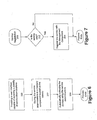
B. Service Registration
Figure 7 is a flow chart diagram illustrating an example of a service
registration process 310. At 312, the system 100 determines whether or not a particular
service 106 or device 104 is new. If the device 104 or service 106 is not new, the
process ends. If the device 104 or service 106 is new, the service 106 or device 104
can be registered with the management component 108 at 314.
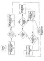
C. Service Request
Figure 8 is a flow chart diagram illustrating an example of a service request
process 320.
At 322, a device 104 can request a reference to a service 106 from the
management component 108.
At 324, the system 100 determines whether or not the requested service 106
has been registered. If the requested service 106 has not been registered, the system
100 at 326 notifies the device 104 that the requested service 106 is not currently
registered, and the process ends. In some embodiments, the system 100 may
automatically prompt the user 114 to see if a registration process should be invoked.
If the requested service has been registered, the system 100 determines at
328 whether or not the requested service 106 is currently in use. If the service 106 is in
use, the system 100 then determines at 336 whether the use is exclusive, e.g. whether
the service is locked with respect to the instant request. If the prior use is exclusive, a
notification is sent at 338. In some embodiments, the system 100 can automatically
notify the user 114 when the exclusive lock expires.
If at 336 the service 106 is not locked for exclusive use, the service 106 can
be registered at 334.
If at 328 the service 106 is not in use, the system 100 determines at 330
whether or not the requested service requires exclusive locking. If exclusive locking is
required, it is performed at 332 before the service is registered at 334. If exclusive
locking is not required, the process proceeds directly to the registering of the service at
334 before the process ends.
D. Service Release Process
Figure 9 is a flow chart diagram illustrating an example of a service release
process 350.
At 352, a device 104 notifies the management component 108 that the device
104 is no longer needed.
At 354, the system 100 determines whether or not the device 104 has the
service 106 locked for exclusive use. If the service 106 is not locked for exclusive use,
the management component 108 deregisters the device 104 at 358 and the process
can end. If the service 106 is exclusively locked, the management component 108 at
356 must also unlock the service 106 in conjunction with the deregistration service at
358
V. ALTERNATIVE EMBODIMENTS
The above description is intended to be illustrative and not restrictive. Many
embodiments and applications other than the examples provided would be apparent to
those of skill in the art upon reading the above description. The scope of the invention
should be determined, not with reference to the above description, but should instead
be determined with reference to the appended claims, along with the full scope of
equivalents to which such claims are entitled. It is anticipated and intended that future
developments will occur in image alignment systems and methods, and that the
invention will be incorporated into such future embodiments.