EP1607678A2 - Lamp with Light Emitting Diodes (LED) to provide a wide beam or a parallel beam - Google Patents
Lamp with Light Emitting Diodes (LED) to provide a wide beam or a parallel beam Download PDFInfo
- Publication number
- EP1607678A2 EP1607678A2 EP05076414A EP05076414A EP1607678A2 EP 1607678 A2 EP1607678 A2 EP 1607678A2 EP 05076414 A EP05076414 A EP 05076414A EP 05076414 A EP05076414 A EP 05076414A EP 1607678 A2 EP1607678 A2 EP 1607678A2
- Authority
- EP
- European Patent Office
- Prior art keywords
- led
- luminaire according
- housing
- lamp
- optical device
- Prior art date
- Legal status (The legal status is an assumption and is not a legal conclusion. Google has not performed a legal analysis and makes no representation as to the accuracy of the status listed.)
- Withdrawn
Links
Images


Classifications
-
- F—MECHANICAL ENGINEERING; LIGHTING; HEATING; WEAPONS; BLASTING
- F21—LIGHTING
- F21V—FUNCTIONAL FEATURES OR DETAILS OF LIGHTING DEVICES OR SYSTEMS THEREOF; STRUCTURAL COMBINATIONS OF LIGHTING DEVICES WITH OTHER ARTICLES, NOT OTHERWISE PROVIDED FOR
- F21V23/00—Arrangement of electric circuit elements in or on lighting devices
- F21V23/04—Arrangement of electric circuit elements in or on lighting devices the elements being switches
-
- F—MECHANICAL ENGINEERING; LIGHTING; HEATING; WEAPONS; BLASTING
- F21—LIGHTING
- F21L—LIGHTING DEVICES OR SYSTEMS THEREOF, BEING PORTABLE OR SPECIALLY ADAPTED FOR TRANSPORTATION
- F21L4/00—Electric lighting devices with self-contained electric batteries or cells
- F21L4/02—Electric lighting devices with self-contained electric batteries or cells characterised by the provision of two or more light sources
- F21L4/022—Pocket lamps
- F21L4/027—Pocket lamps the light sources being a LED
-
- F—MECHANICAL ENGINEERING; LIGHTING; HEATING; WEAPONS; BLASTING
- F21—LIGHTING
- F21S—NON-PORTABLE LIGHTING DEVICES; SYSTEMS THEREOF; VEHICLE LIGHTING DEVICES SPECIALLY ADAPTED FOR VEHICLE EXTERIORS
- F21S9/00—Lighting devices with a built-in power supply; Systems employing lighting devices with a built-in power supply
- F21S9/02—Lighting devices with a built-in power supply; Systems employing lighting devices with a built-in power supply the power supply being a battery or accumulator
- F21S9/03—Lighting devices with a built-in power supply; Systems employing lighting devices with a built-in power supply the power supply being a battery or accumulator rechargeable by exposure to light
-
- F—MECHANICAL ENGINEERING; LIGHTING; HEATING; WEAPONS; BLASTING
- F21—LIGHTING
- F21V—FUNCTIONAL FEATURES OR DETAILS OF LIGHTING DEVICES OR SYSTEMS THEREOF; STRUCTURAL COMBINATIONS OF LIGHTING DEVICES WITH OTHER ARTICLES, NOT OTHERWISE PROVIDED FOR
- F21V14/00—Controlling the distribution of the light emitted by adjustment of elements
- F21V14/04—Controlling the distribution of the light emitted by adjustment of elements by movement of reflectors
- F21V14/045—Controlling the distribution of the light emitted by adjustment of elements by movement of reflectors in portable lighting devices
-
- F—MECHANICAL ENGINEERING; LIGHTING; HEATING; WEAPONS; BLASTING
- F21—LIGHTING
- F21V—FUNCTIONAL FEATURES OR DETAILS OF LIGHTING DEVICES OR SYSTEMS THEREOF; STRUCTURAL COMBINATIONS OF LIGHTING DEVICES WITH OTHER ARTICLES, NOT OTHERWISE PROVIDED FOR
- F21V14/00—Controlling the distribution of the light emitted by adjustment of elements
- F21V14/06—Controlling the distribution of the light emitted by adjustment of elements by movement of refractors
- F21V14/065—Controlling the distribution of the light emitted by adjustment of elements by movement of refractors in portable lighting devices
-
- F—MECHANICAL ENGINEERING; LIGHTING; HEATING; WEAPONS; BLASTING
- F21—LIGHTING
- F21V—FUNCTIONAL FEATURES OR DETAILS OF LIGHTING DEVICES OR SYSTEMS THEREOF; STRUCTURAL COMBINATIONS OF LIGHTING DEVICES WITH OTHER ARTICLES, NOT OTHERWISE PROVIDED FOR
- F21V23/00—Arrangement of electric circuit elements in or on lighting devices
- F21V23/04—Arrangement of electric circuit elements in or on lighting devices the elements being switches
- F21V23/0435—Arrangement of electric circuit elements in or on lighting devices the elements being switches activated by remote control means
-
- F—MECHANICAL ENGINEERING; LIGHTING; HEATING; WEAPONS; BLASTING
- F21—LIGHTING
- F21L—LIGHTING DEVICES OR SYSTEMS THEREOF, BEING PORTABLE OR SPECIALLY ADAPTED FOR TRANSPORTATION
- F21L4/00—Electric lighting devices with self-contained electric batteries or cells
- F21L4/08—Electric lighting devices with self-contained electric batteries or cells characterised by means for in situ recharging of the batteries or cells
-
- F—MECHANICAL ENGINEERING; LIGHTING; HEATING; WEAPONS; BLASTING
- F21—LIGHTING
- F21S—NON-PORTABLE LIGHTING DEVICES; SYSTEMS THEREOF; VEHICLE LIGHTING DEVICES SPECIALLY ADAPTED FOR VEHICLE EXTERIORS
- F21S8/00—Lighting devices intended for fixed installation
- F21S8/08—Lighting devices intended for fixed installation with a standard
-
- F—MECHANICAL ENGINEERING; LIGHTING; HEATING; WEAPONS; BLASTING
- F21—LIGHTING
- F21V—FUNCTIONAL FEATURES OR DETAILS OF LIGHTING DEVICES OR SYSTEMS THEREOF; STRUCTURAL COMBINATIONS OF LIGHTING DEVICES WITH OTHER ARTICLES, NOT OTHERWISE PROVIDED FOR
- F21V29/00—Protecting lighting devices from thermal damage; Cooling or heating arrangements specially adapted for lighting devices or systems
- F21V29/50—Cooling arrangements
- F21V29/502—Cooling arrangements characterised by the adaptation for cooling of specific components
- F21V29/507—Cooling arrangements characterised by the adaptation for cooling of specific components of means for protecting lighting devices from damage, e.g. housings
-
- F—MECHANICAL ENGINEERING; LIGHTING; HEATING; WEAPONS; BLASTING
- F21—LIGHTING
- F21V—FUNCTIONAL FEATURES OR DETAILS OF LIGHTING DEVICES OR SYSTEMS THEREOF; STRUCTURAL COMBINATIONS OF LIGHTING DEVICES WITH OTHER ARTICLES, NOT OTHERWISE PROVIDED FOR
- F21V31/00—Gas-tight or water-tight arrangements
-
- F—MECHANICAL ENGINEERING; LIGHTING; HEATING; WEAPONS; BLASTING
- F21—LIGHTING
- F21W—INDEXING SCHEME ASSOCIATED WITH SUBCLASSES F21K, F21L, F21S and F21V, RELATING TO USES OR APPLICATIONS OF LIGHTING DEVICES OR SYSTEMS
- F21W2131/00—Use or application of lighting devices or systems not provided for in codes F21W2102/00-F21W2121/00
- F21W2131/10—Outdoor lighting
- F21W2131/103—Outdoor lighting of streets or roads
-
- F—MECHANICAL ENGINEERING; LIGHTING; HEATING; WEAPONS; BLASTING
- F21—LIGHTING
- F21Y—INDEXING SCHEME ASSOCIATED WITH SUBCLASSES F21K, F21L, F21S and F21V, RELATING TO THE FORM OR THE KIND OF THE LIGHT SOURCES OR OF THE COLOUR OF THE LIGHT EMITTED
- F21Y2107/00—Light sources with three-dimensionally disposed light-generating elements
- F21Y2107/30—Light sources with three-dimensionally disposed light-generating elements on the outer surface of cylindrical surfaces, e.g. rod-shaped supports having a circular or a polygonal cross section
-
- F—MECHANICAL ENGINEERING; LIGHTING; HEATING; WEAPONS; BLASTING
- F21—LIGHTING
- F21Y—INDEXING SCHEME ASSOCIATED WITH SUBCLASSES F21K, F21L, F21S and F21V, RELATING TO THE FORM OR THE KIND OF THE LIGHT SOURCES OR OF THE COLOUR OF THE LIGHT EMITTED
- F21Y2115/00—Light-generating elements of semiconductor light sources
- F21Y2115/10—Light-emitting diodes [LED]
-
- Y—GENERAL TAGGING OF NEW TECHNOLOGICAL DEVELOPMENTS; GENERAL TAGGING OF CROSS-SECTIONAL TECHNOLOGIES SPANNING OVER SEVERAL SECTIONS OF THE IPC; TECHNICAL SUBJECTS COVERED BY FORMER USPC CROSS-REFERENCE ART COLLECTIONS [XRACs] AND DIGESTS
- Y02—TECHNOLOGIES OR APPLICATIONS FOR MITIGATION OR ADAPTATION AGAINST CLIMATE CHANGE
- Y02B—CLIMATE CHANGE MITIGATION TECHNOLOGIES RELATED TO BUILDINGS, e.g. HOUSING, HOUSE APPLIANCES OR RELATED END-USER APPLICATIONS
- Y02B20/00—Energy efficient lighting technologies, e.g. halogen lamps or gas discharge lamps
- Y02B20/72—Energy efficient lighting technologies, e.g. halogen lamps or gas discharge lamps in street lighting
Definitions
- the present invention relates to a luminaire with a housing, at least one in arranged on the housing LED bulbs and with an optical device which in a distance to the LED light source in a beam path of at least one light beam is arranged and can reflect a light beam and / or break.
- LED light-emitting diode
- the well-known prior art with a LED bulbs shows the disadvantage that such lights are not focusable and therefore only be used to generate a broad jet.
- When trying with a LED bulbs also produce a spot beam, so far it is only possible To produce wide beams with reduced width.
- Such lights can not Generation of a spot beam can be used and are not yet comparable with conventional lights, with which a spot beam can be adjusted.
- the object of the present invention is therefore a luminaire with at least one LED to create as a light source, produced with both wide-beam and a spot beam can be.
- the object is achieved in that the LED bulbs in one is arranged upstream or in the optical device existing focal point.
- the arrangement of the LED light source in the upstream or in the optical Device lying focal point is a prerequisite for using the optical Device, either a reflector, a lens device or a combination same, a spot beam can be generated.
- the optical device has a mirror reflector, the Beam path limited.
- Another advantage of the luminaire according to the invention results when the optical Device having an aspherical lens.
- the distance between the LED bulb and the optical Device can be broad-beam and generate at least one spot beam.
- the lamp can be used as a street lamp. Because of a low energy consumption with optimized emission can be such Street light can be operated with an accumulator powered by solar energy becomes.
- FIG. 6 shows a handheld projector 10 in FIG partially cutaway illustration.
- the hand lamp 10 has a housing 11, which is essentially made in one piece.
- the housing 11 may be made of conventional Materials consist, for example, of aluminum, polyethylene or another suitable material.
- the housing 11 is in the region of an upper side to a handle 12 shaped.
- the housing 11 On both sides of the handle 12 are formed means for fastening a carrying strap, which represent two eyelets 13 in the present embodiment.
- the housing In the area of one Bottom, the housing is formed to bearing surfaces, for example, the illustrated Stand feet 14, with which the hand lamp 10 can be placed on a pad.
- the housing 11 further has an opening which is circular Recess 15 is formed. In other embodiments, the opening may also have other geometric shapes.
- an LED bulb 16 Inside the housing 11 is an LED bulb 16 arranged. The LED illuminant 16 is in the region of the recess 15 of the housing 11 is located and lies at the focal point of an optical device 30 (details run below).
- the optical device 30 comprises in a first embodiment a mirror reflector 30.1 and a windshield 30.2, in a second embodiment only an aspherical lens 30.3 and in a third embodiment a combination of Mirror reflector 30.1 and aspherical lens 30.3.
- a Aspherical lens 30.3 can optionally also be provided with a windshield 30.2.
- a sealing ring 19 is positioned, which prevents the penetration of dust and / or moisture into the housing 11.
- the LED lamp 16 is seated on a holder 19 in the housing 11.
- the holder 19 may consist of an elastic material, such as a plastic or from Rubber 15.
- shocks for example, from the outside on the Housing 11 act, for example, in a rough lowering of the hand lamp 10, damped, so that damage to the LED bulb 16 is avoided.
- a power source 17 for supplying the LED lighting means 16 arranged with energy is in the present case from a plurality of accumulators 18, which are connected via lines 20 to the LED illuminator 16 are connected. Alternatively, batteries can be used for power supply.
- the housing is an on / off switch 23rd assigned, via lines 20 to the accumulators 18 and the LED illuminator 17th connected is.
- acoustic and / or optical Signaling be arranged, for example, a (light) diode or a speaker. These means are used to signal the imminent end of the operating period, ie the time at which the stored energy in the accumulators 18 is consumed or the capacity of the accumulators 18 is exhausted.
- a circuit is arranged in the housing 11, consisting of electronic components 22 on a board 21. Once the capacity of the accumulators falls below a certain threshold, this is determined by the acoustic and / or optical means signaled.
- the circuit on the one hand with the accumulators and on the other hand connected to the acoustic and / or optical means by the Circuit operated automatically.
- the capacity of the accumulators 18 It is also possible to measure the voltage to determine the remaining operating time.
- the operation of the optical and / or acoustic means may, for example, be five minutes take place before the end of the operating period. The time at which before the end of the Battery capacity can be warned by programming the circuit accordingly be adjusted.
- LED lighting means 16 it is also possible to arrange a plurality of LED lighting means 16 in the housing 11. So can For example, two LED bulbs with different energy consumption and be used according to different luminosity, for example 1 watt or more. Depending on the capacity of the accumulators 18, the operation of the two LED bulb 16 automatically controlled by the circuit. In this case, that indicates Housing 11 a single on / off switch 23, with the hand lamp 10 in Operation can be taken. As long as sufficient capacity is available, Both LED bulbs 16 or alternatively the LED bulbs 16 with the larger Energy intake operated. Once the capacity is below a certain threshold falls, the LED bulb 16 is turned off with greater energy consumption and only operated the LED bulb 16 with less energy consumption.
- the LED lighting means 16, a control element for controlling the intensity be associated with the generated light beam, for example, a controller with which the intensity preferably continuously variable.
- the housing 11 also has a socket 24. With the help of the socket 24, the power source 17 and / or the at least one LED lighting means 16 connectable to an external power source. On In this way, the at least one LED illuminant 16 can be independent of the inside of the housing 11 arranged power source 17 are operated. Furthermore, the external Power source can be used to charge the batteries 18.
- the Housing 11 a transport lock 25. With the help of the transport lock 25 of the Operation of the lamps 16 are inhibited regardless of the switch 23. To this In this way, an accidental operation of the handheld spotlight 10 during the Transports are avoided.
- the operation of the portable headlight 10 by means of a wireless Remote control can have an on / off switch, the in its function corresponds to the switch 11 mounted on the housing 11. In this way each lamp 16 can be actuated.
- the remote control can be a controller for the intensity of the generated light beam.
- the Remote but a switch on, with the two aforementioned functions combined are controllable.
- a pushbutton the simple operation of each Lamp 16 turns on or off. A long press on the button is used for control the intensity of the generated light beam, so for dimming.
- the Remote control the same optical and / or acoustic means of signaling the End of the operating time have as the hand lamp 10th
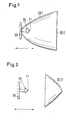
- the LED lamp 16 is disposed at the focal point F1, the upstream ago Exit of a light beam from the lamp is.
- the reflector 30.1 limits the Beam path of the light emitted from the LED bulb 16 light rays.
- On the Opening side of the mirror reflector 30.1 is a translucent disc 30.2 arranged.
- the beam angle of the LED light source is 120 to 160 °.
- the distance of the LED bulb 16 of the mirror reflector 30.1 is changeable (see Pfeilrichtng), depending after, whether a wide beam or a spot beam is to be generated.
- a second embodiment of the optical device 30 is shown.
- the LED bulb 16 is in the downstream focal point 1 of an aspheric lens 30.3 arranged.
- the aspherical lens 30.3 is with a straight base 30.4 the LED bulb 16 facing.
- the distance between the LED bulb 16 and the aspherical lens 30.3 changeable, depending on whether a Wide beam or a spot beam to be generated.
- the change in the distance between the LED bulb 16 and the optical Device 30 is effected by known adjusting means, which are not described here should be. In general, the optical device 30 will be adjusted and not the LED bulb 16.
- the LED illuminant 16 is in relation to the optical device 30 Third embodiment of the present invention shown schematically.
- the LED bulb 16 is also in a mirror reflector 30.1 and Although at the focal point F1, but there is rotatably mounted. The rotation takes place around with a Primary light beam coincident optical axis.
- Such an embodiment is Can be used in a beacon, for example a blue light.
- a power transmission takes place in this embodiment via a slip ring (not shown), with carbon brushes. With a 1 watt LED, it is possible to the legally prescribed amount of light produce.
- a holder for a plurality of LED bulbs is shown schematically, in a lamp according to the present invention can be used.
- a triangular or polygonal carrier 31, with an appropriate number of faces, in the middle an all-round beacon is installed, has at least one side surface 32 at least LED bulb 16 on.
- At least one aspheric lens 30.3 moves concentrically around the carrier 31, at a distance through which the LED lighting means 16 lie in the central focus F1 of the aspheric lens.
- the carrier has four side surfaces 32, so that four LED bulbs with a beam angle of 110 ° the meet legal requirements for an all-round light of 360 °.
- a light reflector 30.1 be used instead of the aspherical lens 30.3, in this embodiment.
- the light reflector 30.1 then rotates at such a distance around the LED bulbs 16 that they are in the focal point F1.
- Fig. 5 is schematically the upper part of a street lamp, a so-called Street lighting, shown.
- the street lighting will be at least one LED bulb 16 and preferably operated with a plurality of LED bulbs 16.
- the LED bulbs 16 have a beam angle of 110 ° or more.
- the optical device 30 is operated with an aspherical lens 30.3.
- the street lighting can be operated with an accumulator as an energy source, as already above for the hand lamp was described.
- the accumulator can be powered by solar energy and the appropriate device, which is well known and not the subject of present invention is to be fed constantly.
- the accumulator sits in Mast of such street lighting and has a sensor for day and night Night on.
- a flashlight 100 is shown schematically as z. B. often in the Military is used.
- a flashlight 100 has a housing 101 made of conventional materials can be made, for. As aluminum, polyethylene, steel or from another suitable material.
- the housing 101 has an approximately cuboid shape, with a large front surface 103, a large rear surface 105, two smaller longitudinal side surfaces 106 and two smaller ones End faces 107.
- a Housing opening 109 is formed in one half.
- the housing opening 109 serves as a light exit opening.
- This optical device 30 can in the flashlight 100 in one of be formed above embodiments. Inexpensive and currently preferred but the first embodiment with a mirror reflector 30.1.
- the arrangement of the LED bulb 16 takes place as in the above embodiments in the focal point F1.
- Housing opening 109 has a diameter of at least 35 mm and the radiation angle can be set as needed, including the above ranges from 120 to 160 ° under or exceed.
- a device 111 for guiding and Actuation of a Ablendschiebers 113 and at least one color filter 115 is formed, such that the Ablendschieber 113 and the at least one color filter 115 is operated freely and pushed in front of the housing opening 109 or from its position in front of the Housing opening 109 can be pushed away. This allows the exiting Light intensity influenced and light signals are generated.
Abstract
Description
Die vorliegende Erfindung betrifft eine Leuchte mit einem Gehäuse, wenigstens einem in dem Gehäuse angeordneten LED-Leuchtmittel und mit einer optischen Einrichtung, die in einem Abstand zum LED-Leuchtmittel in einem Strahlengang wenigstens eines Lichtstrahls angeordnet ist und einen Lichtstrahl reflektieren und/oder brechen kann .The present invention relates to a luminaire with a housing, at least one in arranged on the housing LED bulbs and with an optical device which in a distance to the LED light source in a beam path of at least one light beam is arranged and can reflect a light beam and / or break.
Solche Leuchten sind aus dem allgemeinen Stand der Technik bekannt.Such lights are known from the general state of the art.
Heute wird als Ersatz für Halogen-Lampen oder andere bekannte Lichtquellen häufig eine LED (Leuchtdiode) in eine Leuchte eingesetzt. Der bekannte Stand der Technik mit einer LED als Leuchtmittel zeigt den Nachteil, dass solche Leuchten nicht fokussierbar sind und daher nur zur Erzeugung eines Breitstrahles eingesetzt werden. Bei dem Versuch mit einem LED-Leuchtmittel auch einen Punktstrahl zu erzeugen, gelingt es bisher lediglich, Breitstrahlen mit reduzierter Breite zu erzeugen. Solche Leuchten können nicht zur Erzeugung eines Punktstrahls eingesetzt werden und sind bisher nicht vergleichbar mit herkömmlichen Leuchten, mit denen ein Punktstrahl eingestellt werden kann.Today, as a substitute for halogen lamps or other known light sources is often a LED (light-emitting diode) inserted into a luminaire. The well-known prior art with a LED bulbs shows the disadvantage that such lights are not focusable and therefore only be used to generate a broad jet. When trying with a LED bulbs also produce a spot beam, so far it is only possible To produce wide beams with reduced width. Such lights can not Generation of a spot beam can be used and are not yet comparable with conventional lights, with which a spot beam can be adjusted.
Die Aufgabe der vorliegenden Erfindung ist daher, eine Leuchte mit wenigstens einer LED als Leuchtmittel zu schaffen, mit der sowohl Breitstrahlen als auch ein Punktstrahl erzeugt werden kann.The object of the present invention is therefore a luminaire with at least one LED to create as a light source, produced with both wide-beam and a spot beam can be.
Die Aufgabe wird erfindungsgemäß dadurch gelöst, dass das LED-Leuchtmittel in einem stromaufwärts oder in der optischen Einrichtung vorhandenen Brennpunkt angeordnet ist.The object is achieved in that the LED bulbs in one is arranged upstream or in the optical device existing focal point.
Die Anordnung des LED-Leuchtmittels in dem stromaufwärts oder in der optischen Einrichtung liegenden Brennpunkt ist Voraussetzung dafür, dass mit Hilfe der optischen Einrichtung, entweder eines Reflektors, einer Linseneinrichtung oder einer Kombination derselben, ein Punktstrahl erzeugt werden kann.The arrangement of the LED light source in the upstream or in the optical Device lying focal point is a prerequisite for using the optical Device, either a reflector, a lens device or a combination same, a spot beam can be generated.
Es ist von Vorteil, wenn die optische Einrichtung einen Spiegelreflektor aufweist, der den Strahlengang begrenzt.It is advantageous if the optical device has a mirror reflector, the Beam path limited.
Ein weiterer Vorteil der erfindungsgemäßen Leuchte ergibt sich, wenn die optische Einrichtung eine asphärische Linse aufweist. Another advantage of the luminaire according to the invention results when the optical Device having an aspherical lens.
Durch die Veränderung des Abstandes zwischen dem LED-Leuchtmittel und der optischen Einrichtung lassen sich Breitstrahlen und wenigstens ein Punktstrahl erzeugen.By changing the distance between the LED bulb and the optical Device can be broad-beam and generate at least one spot beam.
Erfindungsgemäß kann die Leuchte als Straßenleuchte verwendet werden. Aufgrund eines geringen Energieverbrauches bei optimierter Abstrahlwirkung kann eine solche Straßenleuchte mit einem Akkumulator betrieben werden, der durch Solarenergie gespeist wird.According to the invention, the lamp can be used as a street lamp. Because of a low energy consumption with optimized emission can be such Street light can be operated with an accumulator powered by solar energy becomes.
Weitere Vorteile der vorliegenden Erfindung ergeben sich aus den Merkmalen der weiteren Unteransprüche.Further advantages of the present invention will become apparent from the features of the other Dependent claims.
Ausführungsformen der vorliegenden Erfindung werden im Folgenden anhand der
Zeichnungen näher beschrieben. Es zeigen:
In Fig. 1 ist schematisch der Teil einer Leuchte dargestellt, der mit der Abstrahlcharakteristik
einer Leuchte zu tun hat. Eine vollständige Leuchte, die die in Fig. 1 dargestellten Bauteile
enthalten kann, ist in Fig. 6 schematisch dargestellt. Die in Fig. 6 dargestellte Leuchte ist ein
Handscheinwerfer, in anderen Ausführungsformen kann eine solche Leuchte aber auch eine
Standleuchte oder eine Straßenlaterne sein. Am Beispiel des Handscheinwerfers aus Fig. 6
wird nun der allgemeine Aufbau beschrieben. Figur 6 zeigt einen Handscheinwerfer 10 in
teilweise aufgeschnittener Darstellung. Der Handscheinwerfer 10 verfügt über ein Gehäuse
11, das im Wesentlichen in einem Stück gefertigt ist. Das Gehäuse 11 kann aus üblichen
Materialien bestehen, zum Beispiel aus Aluminium, Polyethylen oder einem anderen
geeigneten Material. Das Gehäuse 11 ist im Bereich einer Oberseite zu einem Griff 12
geformt. Beidseitig des Griffs 12 sind Mittel zur Befestigung eines Tragegurtes ausgebildet,
die in der vorliegenden Ausführungsform zwei Ösen 13 darstellen. Im Bereich einer
Unterseite ist das Gehäuse zu Auflageflächen ausgeformt, zum Beispiel den dargestellten
Standfüßen 14, mit denen der Handscheinwerfer 10 auf einer Unterlage abstellbar ist. An
einer Seite weist das Gehäuse 11 weiterhin eine Öffnung auf, die als kreisförmige
Ausnehmung 15 ausgebildet ist. In anderen Ausführungsformen kann die Öffnung auch
andere geometrische Formen haben. Im Inneren des Gehäuses 11 ist ein LED-Leuchtmittel
16 angeordnet. Das LED-Leuchtmittel 16 ist im Bereich der Ausnehmung 15 des Gehäuses
11 angeordnet und liegt im Brennpunkt einer optischen Einrichtung 30 (Einzelheiten werden
unten ausgeführt). Die optische Einrichtung 30 umfasst in einer ersten Ausführungsform
einen Spiegelreflektor 30.1 und eine Frontscheibe 30.2, in einer zweiten Ausführungsform
nur eine asphärische Linse 30.3 und in einer dritten Ausführungsform eine Kombination aus
Spiegelreflektor 30.1 und asphärischer Linse 30.3. In den Ausführungsformen mit einer
asphärischen Linse 30.3 kann optional auch eine Frontscheibe 30.2 vorgesehen sein.
Zwischen der optischen Einrichtung 30 und dem Gehäuse 11 ist ein Dichtring 19 positioniert,
der das Eindringen von Staub und/oder Feuchtigkeit in das Gehäuse 11 verhindert.In Fig. 1 the part of a lamp is shown schematically, with the radiation characteristic
a lamp has to do. A complete lamp, the components shown in Fig. 1
may be shown schematically in Fig. 6. The lamp shown in Fig. 6 is a
Hand lamp, in other embodiments, such a light but also a
Floor lamp or a street lamp. Using the example of the hand-held spotlight from FIG. 6
Now, the general structure will be described. FIG. 6 shows a
Das LED-Leuchtmittel 16 sitzt auf einer Halterung 19 im Gehäuse 11. Die Halterung 19 kann
aus einem elastischen Material bestehen, beispielsweise aus einem Kunststoff oder aus
Gummi 15. Durch die Halterung 19 werden Stöße, die beispielsweise von außen auf das
Gehäuse 11 einwirken, zum Beispiel bei einem unsanften Absetzen des Handscheinwerfers
10, gedämpft, sodass eine Beschädigung des LED-Leuchtmittels 16 vermieden wird.The
Weiterhin ist im Inneren des Gehäuses 11 eine Stromquelle 17 zur Versorgung des LED-Leuchtmittels
16 mit Energie angeordnet. Die Stromquelle 17 besteht im vorliegenden Fall
aus mehreren Akkumulatoren 18, die über Leitungen 20 mit dem LED-Leuchtmittel 16
verbunden sind. Alternativ können auch Batterien zur Stromversorgung eingesetzt werden.
Zur Inbetriebnahme des Handscheinwerfers 10 ist dem Gehäuse ein Ein-/Aus-Schalter 23
zugeordnet, der über Leitungen 20 mit den Akkumulatoren 18 und dem LED-Leuchtmittel 17
verbunden ist.Furthermore, in the interior of the
Im Bereich des Gehäuses 11 können weiterhin Mittel zur akustischen und/oder optischen
Signalisierung angeordnet sein, beispielsweise eine (Leucht-)Diode bzw. ein Lautsprecher.
Diese Mittel dienen zur Signalisierung des bevorstehenden Endes der Betriebsdauer, also
dem Zeitpunkt, zu dem die in den Akkumulatoren 18 gespeicherte Energie verbraucht ist
bzw. die Kapazität der Akkumulatoren 18 erschöpft ist. Zur Ermittelung der Kapazität der
Akkumulatoren 18 ist im Gehäuse 11 eine Schaltung angeordnet, bestehend aus
elektronischen Bauteilen 22 auf einer Platine 21. Sobald die Kapazität der Akkumulatoren
unter einen bestimmten Schwellenwert fällt, wird dies durch die akustischen und/oder
optischen Mittel signalisiert. Hierzu ist die Schaltung einerseits mit den Akkumulatoren und
andererseits mit den akustischen und/oder optischen Mitteln verbunden, die durch die
Schaltung automatisch betätigt werden. An der Stelle der Kapazität der Akkumulatoren 18
kann auch die Spannung zur Ermittlung der verbleibenden Betriebsdauer gemessen werden.
Die Betätigung der optischen und/oder akustischen Mittel kann beispielsweise fünf Minuten
vor Ende der Betriebsdauer erfolgen. Der Zeitpunkt, an dem vor dem Ende der
Batteriekapazität gewarnt wird, kann durch entsprechende Programmierung der Schaltung
angepasst werden.In the region of the
Es können auch mehrere LED-Leuchtmittel 16 im Gehäuse 11 angeordnet sein. So können
beispielsweise zwei LED-Leuchtmittel mit unterschiedlicher Energieaufnahme und
entsprechend unterschiedlicher Leuchtkraft eingesetzt werden, zum Beispiel 1 Watt oder
mehr. In Abhängigkeit von der Kapazität der Akkumulatoren 18 wird der Betrieb der beiden
LED-Leuchtmittel 16 automatisch von der Schaltung gesteuert. In diesem Fall weist das
Gehäuse 11 einen einzelnen Ein-/Aus-Schalter 23 auf, mit dem Handscheinwerfer 10 in
Betrieb genommen werden kann. Solange eine ausreichende Kapazität vorhanden ist,
werden beide LED-Leuchtmittel 16 oder alternativ das LED-Leuchtmittel 16 mit der größeren
Energieaufnahme betrieben. Sobald die Kapazität unter einem bestimmten Schwellenwert
fällt, wird das LED-Leuchtmittel 16 mit größerer Energieaufnahme abgeschaltet und
ausschließlich das LED-Leuchtmittel 16 mit geringerer Energieaufnahme betrieben.It is also possible to arrange a plurality of LED lighting means 16 in the
Weiterhin kann den LED-Leuchtmitteln 16 ein Bedienelement zur Regelung der Intensität
des erzeugten Lichtstrahls zugeordnet sein, beispielsweise ein Regler, mit dem die Intensität
vorzugsweise stufenlos regelbar ist. Im gezeigten Ausführungsbeispiel weist das Gehäuse
11 weiterhin eine Buchse 24 auf. Mit Hilfe der Buchse 24 ist die Stromquelle 17 und/oder
das wenigstens ein LED-Leuchtmittel 16 mit einer externen Stromquelle verbindbar. Auf
diese Weise kann das wenigstens eine LED-Leuchtmittel 16 unabhängig von der im Inneren
des Gehäuses 11 angeordneten Stromquelle 17 betrieben werden. Ferner kann die externe
Stromquelle dazu benutzt werden, die Akkumulatoren 18 aufzuladen. Weiter weist das
Gehäuse 11 eine Transportsicherung 25 auf. Mit Hilfe der Transportsicherung 25 kann der
Betrieb der Leuchtmittel 16 unabhängig vom Schalter 23 unterbunden werden. Auf diese
Weise kann ein versehentliches Betätigen des Handscheinwerfers 10 während des
Transports vermieden werden.Furthermore, the LED lighting means 16, a control element for controlling the intensity
be associated with the generated light beam, for example, a controller with which the intensity
preferably continuously variable. In the embodiment shown, the
Vorteilhaft ist die Bedienung des Handscheinwerfers 10 mittels einer kabellosen
Fernbedienung. Hierzu kann die Fernbedienung einen Ein-/Aus-Schalter aufweisen, der in
seiner Funktion dem am Gehäuse 11 angebrachten Schalter 23 entspricht. Auf diese Weise
kann jedes Leuchtmittel 16 betätigt werden. Weiterhin kann die Fernbedienung einen Regler
für die Intensität des erzeugen Lichtstrahles aufweisen. Vorzugsweise weist die
Fernbedienung jedoch einen Schalter auf, mit dem beiden vorgenannten Funktionen
kombiniert steuerbar sind. Beispielsweise einem Taster, der bei einfacher Betätigung jedes
Leuchtmittel 16 ein- oder ausschaltet. Ein längerer Druck auf den Taster dient zur Regelung
der Intensität des erzeugten Lichtstrahls, also zur Dimmung. Weiterhin kann die
Fernbedienung die gleichen optischen und/oder akustischen Mittel zur Signalisierung des
Endes der Betriebszeit aufweisen wie der Handscheinwerfer 10.Advantageously, the operation of the
In Fig. 1 ist das LED-Leuchtmittel 16 im Brennpunkt F1 angeordnet, der stromaufwärts vor
Austritt eines Lichtstrahls aus der Leuchte liegt. Der Reflektor 30.1 begrenzt den
Strahlengang der von dem LED-Leuchtmittel 16 emittierten Lichtstrahlen. Auf der
Öffnungsseite des Spiegelreflektors 30.1 ist eine lichtdurchlässige Scheibe 30.2 angeordnet.
Der Abstrahlwinkel des LED-Leuchtmittels beträgt 120 bis 160°. Der Abstand des LED-Leuchtmittels
16 von dem Spiegelreflektor 30.1 ist veränderbar (siehe Pfeilrichtng), je
nachdem, ob ein Breitstrahl oder ein Punktstrahl erzeugt werden soll.In Fig. 1, the
In Fig. 2 ist eine zweite Ausführungsform der optischen Einrichtung 30 dargestellt. Das LED-Leuchtmittel
16 ist im stromabwärts liegenden Brennpunkt 1 einer asphärischen Linse 30.3
angeordnet. Die asphärische Linse 30.3 ist mit einer geraden Grundfläche 30.4 dem LED-Leuchtmittel
16 zugewandt. Auch in der zweiten Ausführungsform ist der Abstand zwischen
dem LED-Leuchtmittel 16 und der asphärischen Linse 30.3 veränderbar, je nachdem, ob ein
Breitstrahl oder ein Punktstrahl erzeugt werden soll.2, a second embodiment of the optical device 30 is shown. The
Die Veränderung des Abstandes zwischen dem LED-Leuchtmittel 16 und der optischen
Einrichtung 30 erfolgt durch bekannte Verstellungsmittel, die hier nicht näher beschrieben
werden sollen. In der Regel wird die optische Einrichtung 30 verstellt werden und nicht das
LED-Leuchtmittel 16.The change in the distance between the
In Fig. 3 ist das LED-Leuchtmittel 16 in Bezug zu der optischen Einrichtung 30 in einer
dritten Ausführungsform der vorliegenden Erfindung schematisch dargestellt. In der dritten
Ausführungsform liegt das LED-Leuchtmittel 16 auch in einem Spiegelreflektor 30.1 und
zwar im Brennpunkt F1, ist dort aber drehbar gelagert. Die Drehung erfolgt um die mit einem
Primär-Lichtstrahl zusammenfallende optische Achse. Eine solche Ausführungsform ist
einsetzbar in einer Kennleuchte, zum Beispiel einem Blaulicht. Eine Stromübertragung
erfolgt in dieser Ausführungsform über einen Schleifring (nicht dargestellt), mit Kohlebürsten.
Mit einer 1 Watt LED ist es möglich, die gesetzlich vorgeschriebene Lichtmenge zu
erzeugen.In FIG. 3, the
In Fig. 4 ist schematisch eine Halterung für mehrere LED-Leuchtmittel dargestellt, die in einer Leuchte gemäß vorliegender Erfindung Verwendung finden kann.In Fig. 4, a holder for a plurality of LED bulbs is shown schematically, in a lamp according to the present invention can be used.
Ein drei- oder mehrkantiger Träger 31, mit entsprechender Flächenzahl, der in der Mitte
einer Rundum-Kennleuchte eingebaut ist, weist an jeder Seitenfläche 32 wenigstens ein
LED-Leuchtmittel 16 auf. Wenigstens eine asphärische Linse 30.3 bewegt sich konzentrisch
um den Träger 31 herum, und zwar in einem Abstand, durch welchen die LED-Leuchtmittel
16 im zentralen Brennpunkt F1 der asphärischen Linse liegen. Vorzugsweise hat der Träger
vier Seitenflächen 32, sodass vier LED-Leuchtmittel mit einem Abstrahlwinkel von 110° die
gesetzlichen Voraussetzungen für ein Rundum-Licht von 360° erfüllen. A triangular or polygonal carrier 31, with an appropriate number of faces, in the middle
an all-round beacon is installed, has at least one side surface 32 at
Anstelle der asphärischen Linse 30.3 kann in dieser Ausführungsform auch ein Lichtreflektor
30.1 verwendet werden. Der Lichtreflektor 30.1 dreht sich dann in einem solchen Abstand
um die LED-Leuchtmittel 16 herum, dass diese in dem Brennpunkt F1 liegen.Instead of the aspherical lens 30.3, in this embodiment, a light reflector
30.1 be used. The light reflector 30.1 then rotates at such a distance
around the
In Fig. 5 ist schematisch der obere Teil einer Straßenlaterne, eine sogenannte
Straßenbeleuchtung, dargestellt. Die Straßenbeleuchtung wird wenigstens einem LED-Leuchtmittel
16 und vorzugsweise mit mehreren LED-Leuchtmitteln 16 betrieben. Die LED-Leuchtmittel
16 haben einen Abstrahlwinkel von 110° oder mehr. Die optische Einrichtung 30
wird mit einer asphärischen Linse 30.3 betrieben.In Fig. 5 is schematically the upper part of a street lamp, a so-called
Street lighting, shown. The street lighting will be at least one
Aufgrund der Verwendung energiesparender LED-Leuchtmittel kann die Straßenbeleuchtung mit einem Akkumulator als Energiequelle betrieben werden, wie dies bereits vorstehend für den Handstrahler beschrieben wurde. Der Akkumulator kann durch Solarenergie und die entsprechende Einrichtung, die allgemein bekannt ist und nicht Gegenstand der vorliegenden Erfindung ist, ständig gespeist werden. Vorzugsweise sitzt der Akkumulator im Mast einer solchen Straßenbeleuchtung und weist einen Sensor für Tag- und Nachteinschaltung auf.Due to the use of energy-saving LED bulbs, the street lighting can be operated with an accumulator as an energy source, as already above for the hand lamp was described. The accumulator can be powered by solar energy and the appropriate device, which is well known and not the subject of present invention is to be fed constantly. Preferably, the accumulator sits in Mast of such street lighting and has a sensor for day and night Night on.
In Fig. 7 ist schematisch eine Taschenleuchte 100 dargestellt, wie sie z. B. häufig auch beim
Militär zum Einsatz kommt. Eine solche Taschenleuchte 100 hat ein Gehäuse 101, das aus
üblichen Materialien hergestellt sein kann, z. B. Aluminium, Polyethylen, Stahlblech oder
aus einem anderen geeigneten Material.In Fig. 7, a
Das Gehäuse 101 hat eine in etwa quaderförmige Gestalt, mit einer großen Frontfläche 103,
einer großen Rückfläche 105, zwei kleineren Längsseitenflächen 106 und zwei kleineren
Stirnseitenflächen 107. In der Frontfläche 103 ist in Bezug zur Längsrichtung, d. h., der
längsten Erstreckung der Frontfläche 103 und Rückfläche 105, in einer Hälfte eine
Gehäuseöffnung 109 ausgebildet. Die Gehäuseöffnung 109 dient als Lichtaustrittsöffnung. In
dem Gehäuse 101, räumlich vor der Gehäuseöffnung 109, befindet sich die optische
Einrichtung 30. Diese optische Einrichtung 30 kann in der Taschenleuchte 100 in einer der
vorstehenden Ausführungsformen ausgebildet sein. Preiswerte und derzeit bevorzugt ist
aber die erst Ausführungsform mit einem Spiegelreflektor 30.1. Die Anordnung des LED-Leuchtmittels
16 erfolgt wie in den vorstehenden Ausführungsformen im Brennpunkt F1. The
Gehäuseöffnung 109 hat einen Durchmesser von wenigstens 35 mm und der Abstrahlwinkel
kann bedarfsgerecht eingestellt sein, also auch die oben angegebenen Bereiche von 120 bis
160° unter- bzw. überschreiten.
Vor der Gehäuseöffnung 109 gibt es in der Regel keine Fokussiereinrichtungen, diese sind
aber denkbar. Allerdings ist auf der Frontfläche 103 eine Einrichtung 111 zur Führung und
Betätigung eines Ablendschiebers 113 und wenigstens eines Farbfilters 115 ausgebildet,
derart, dass der Ablendschieber 113 und der wenigstens eine Farbfilter 115 wahlfrei betätigt
und vor die Gehäuseöffnung 109 geschoben oder aus dessen Position vor der
Gehäuseöffnung 109 weggeschoben werden kann. Dadurch können die austretende
Lichtintensität beeinflusst und Leuchtsignale erzeugt werden.In front of the
Claims (14)
dadurch gekennzeichnet, dass das LED-Leuchtmittel (16) in einem stromaufwärts der optischen Einrichtung (30) vorhandenen Brennpunkt (F1) angeordnet ist.Luminaire with a housing, at least one LED illuminant arranged in the housing and with an optical device which is arranged at a distance from the LED illuminant in a beam path of at least one light beam,
characterized in that the LED lighting means (16) in a current upstream of the optical device (30) existing focus (F1) is arranged.
dadurch gekennzeichnet, dass die optische Einrichtung (30) einen Spiegelreflektor (30.1) aufweist, den Strahlengang begrenzt.Luminaire according to claim 1,
characterized in that the optical device (30) has a mirror reflector (30.1), the beam path limited.
dadurch gekennzeichnet, dass die optische Einrichtung (30) eine asphärische Linse (30.3) aufweist..Luminaire according to claim 1 or 2,
characterized in that the optical device (30) comprises an aspherical lens (30.3).
dadurch gekennzeichnet, dass der Abstand zwischen jedem LED-Leuchtmittel (16) und der optischen Einrichtung (30) veränderbar ist.Luminaire according to one of claims 1 to 3,
characterized in that the distance between each LED illuminant (16) and the optical device (30) is variable.
dadurch gekennzeichnet, dass jedes LED-Leuchtmittel (16) um eine mit einem Primär-Lichtstrahl zusammenfallende Achse drehbar angeordnet ist.Luminaire according to claim 1 or 2,
characterized in that each LED illuminant (16) is rotatably disposed about an axis coincident with a primary light beam.
dadurch gekennzeichnet, dass jedes LED-Leuchtmittel (16) auf einer Seitenfläche (32) eines mehrseitigen Trägers (31) angeordnet ist und der Spiegelreflektor (30.1) um den mehrseitigen Träger (31) herum drehbar angeordnet ist.Luminaire according to claim 2,
characterized in that each LED illuminant (16) is disposed on a side surface (32) of a multi-sided carrier (31) and the specular reflector (30.1) is rotatably disposed about the multi-sided carrier (31).
dadurch gekennzeichnet, dass jedes LED-Leuchtmittel (16) auf einer Seitenfläche (32) eines mehrseitigen Trägers (31) angeordnet ist und wenigstens eine sphärische Linse (30.3) um den mehrseitigen Träger (31) herum drehbar angeordnet ist. Luminaire according to claim 3,
characterized in that each LED illuminant (16) is disposed on a side surface (32) of a multi-sided carrier (31) and at least one spherical lens (30.3) is rotatably disposed about the multi-sided carrier (31).
gekennzeichnet durch einen Akkumulator (18) als Energiequelle.Luminaire according to one of claims 1 to 7,
characterized by an accumulator (18) as an energy source.
dadurch gekennzeichnet, dass das oder jedes Leuchtmittel (16) durch eine kabellose Fernbedienung betätigbar ist.Luminaire according to one of claims 1 to 8,
characterized in that the or each lighting means (16) is operable by a wireless remote control.
dadurch gekennzeichnet, dass ein Absinken der Kapazität einer Energiequelle unter einem bestimmten Schwellenwert durch optische und/oder akustische Mittel signalisierbar ist.Luminaire according to claim 9,
characterized in that a decrease in the capacity of a power source below a certain threshold by optical and / or acoustic means is signaled.
dadurch gekennzeichnet, dass die Intensität des wenigstens einen erzeugten Lichtstrahls vorzugsweise stufenlos regelbar ist.Luminaire according to claim 9 or 10,
characterized in that the intensity of the at least one generated light beam is preferably infinitely variable.
dadurch gekennzeichnet, dass das Gehäuse () einen Ablendschieber () aufweist, der in den Strahlengang des wenigstens einen Lichtstrahls hinein und aus diesem heraus bewegbar angeordnet ist.Luminaire according to one of the preceding claims,
characterized in that the housing (12) comprises a capping slide (12) which is movably arranged in and out of the beam path of the at least one light beam.
Applications Claiming Priority (4)
| Application Number | Priority Date | Filing Date | Title |
|---|---|---|---|
| DE202004009691U | 2004-06-15 | ||
| DE202004009691U DE202004009691U1 (en) | 2004-06-15 | 2004-06-15 | Electrical light for use in a torch has a light emitting diode that can be adjusted relative to focal point of a reflector |
| DE202004019939U DE202004019939U1 (en) | 2004-06-15 | 2004-12-21 | Electrical lighting unit uses LED modules for use in such as a pocket torch or street light |
| DE202004019939U | 2004-12-21 |
Publications (2)
| Publication Number | Publication Date |
|---|---|
| EP1607678A2 true EP1607678A2 (en) | 2005-12-21 |
| EP1607678A3 EP1607678A3 (en) | 2007-07-11 |
Family
ID=34938346
Family Applications (1)
| Application Number | Title | Priority Date | Filing Date |
|---|---|---|---|
| EP05076414A Withdrawn EP1607678A3 (en) | 2004-06-15 | 2005-06-14 | Lamp with Light Emitting Diodes (LED) to provide a wide beam or a parallel beam |
Country Status (1)
| Country | Link |
|---|---|
| EP (1) | EP1607678A3 (en) |
Cited By (5)
| Publication number | Priority date | Publication date | Assignee | Title |
|---|---|---|---|---|
| EP1801488A1 (en) * | 2005-12-23 | 2007-06-27 | Willi Houben | Lamp |
| DE102007041842A1 (en) * | 2007-08-27 | 2009-03-05 | Swb Netze Gmbh & Co. Kg | Street lighting controlling method, involves providing generated electrical energy as alternating voltage by inverter module for supplying into mains supply of electrical line from photovoltaic generator to network connection |
| DE102013013411A1 (en) | 2013-08-08 | 2015-02-12 | Friedrich Grimm | LUMINOUS DIODE AND LIGHT DIODE LAYOUT FOR A HEADLIGHT |
| CN105202420A (en) * | 2015-10-12 | 2015-12-30 | 漳州立达信灯具有限公司 | Reflection type music lamp |
| DE102009044387B4 (en) * | 2009-11-02 | 2017-05-24 | Selux Aktiengesellschaft | LED outdoor light |
Citations (6)
| Publication number | Priority date | Publication date | Assignee | Title |
|---|---|---|---|---|
| US5490045A (en) * | 1994-09-29 | 1996-02-06 | Elgin Molded Plastics, Inc. | Barrier light with lens-coupled, self-orienting limited field light source |
| FR2745627A1 (en) * | 1996-03-04 | 1997-09-05 | Grimaud Jacques | Pocket torch with adjustable reflecting surface fitted over its end |
| DE20006963U1 (en) * | 2000-04-14 | 2000-08-24 | Kennleuchten Tech Anlagen Gmbh | Signaling device |
| US6190020B1 (en) * | 1999-06-23 | 2001-02-20 | Fred Jack Hartley | Light producing assembly for a flashlight |
| WO2002101285A1 (en) * | 2001-06-08 | 2002-12-19 | Advanced Leds Limited | Exterior luminaire |
| US20030147237A1 (en) * | 2002-02-01 | 2003-08-07 | Halasz Christopher Lee | Flashlight |
-
2005
- 2005-06-14 EP EP05076414A patent/EP1607678A3/en not_active Withdrawn
Patent Citations (6)
| Publication number | Priority date | Publication date | Assignee | Title |
|---|---|---|---|---|
| US5490045A (en) * | 1994-09-29 | 1996-02-06 | Elgin Molded Plastics, Inc. | Barrier light with lens-coupled, self-orienting limited field light source |
| FR2745627A1 (en) * | 1996-03-04 | 1997-09-05 | Grimaud Jacques | Pocket torch with adjustable reflecting surface fitted over its end |
| US6190020B1 (en) * | 1999-06-23 | 2001-02-20 | Fred Jack Hartley | Light producing assembly for a flashlight |
| DE20006963U1 (en) * | 2000-04-14 | 2000-08-24 | Kennleuchten Tech Anlagen Gmbh | Signaling device |
| WO2002101285A1 (en) * | 2001-06-08 | 2002-12-19 | Advanced Leds Limited | Exterior luminaire |
| US20030147237A1 (en) * | 2002-02-01 | 2003-08-07 | Halasz Christopher Lee | Flashlight |
Cited By (5)
| Publication number | Priority date | Publication date | Assignee | Title |
|---|---|---|---|---|
| EP1801488A1 (en) * | 2005-12-23 | 2007-06-27 | Willi Houben | Lamp |
| DE102007041842A1 (en) * | 2007-08-27 | 2009-03-05 | Swb Netze Gmbh & Co. Kg | Street lighting controlling method, involves providing generated electrical energy as alternating voltage by inverter module for supplying into mains supply of electrical line from photovoltaic generator to network connection |
| DE102009044387B4 (en) * | 2009-11-02 | 2017-05-24 | Selux Aktiengesellschaft | LED outdoor light |
| DE102013013411A1 (en) | 2013-08-08 | 2015-02-12 | Friedrich Grimm | LUMINOUS DIODE AND LIGHT DIODE LAYOUT FOR A HEADLIGHT |
| CN105202420A (en) * | 2015-10-12 | 2015-12-30 | 漳州立达信灯具有限公司 | Reflection type music lamp |
Also Published As
| Publication number | Publication date |
|---|---|
| EP1607678A3 (en) | 2007-07-11 |
Similar Documents
| Publication | Publication Date | Title |
|---|---|---|
| EP2136126B1 (en) | Operating light | |
| DE60129987T2 (en) | FLASHLIGHT WITH ONE LED | |
| EP2136128A1 (en) | Operating light | |
| DE102020105965B4 (en) | Luminaire with variable beam angle and fixed light intensity in the center of the beam | |
| EP1893910B1 (en) | Portable light | |
| EP1422467A2 (en) | Mobile lamp | |
| EP1607678A2 (en) | Lamp with Light Emitting Diodes (LED) to provide a wide beam or a parallel beam | |
| DE202015009650U1 (en) | Double Focus Flashlight | |
| EP0921345A2 (en) | Portable lamp, in particular pocket lamp | |
| DE202004021854U1 (en) | surgical light | |
| DE202009016976U1 (en) | Light source, headlight of a means of transport and optical system of the light source | |
| DE202004019939U1 (en) | Electrical lighting unit uses LED modules for use in such as a pocket torch or street light | |
| DE102013101794A1 (en) | Adjustable focus-rod flashlight has light emitting diode with light emitting diode module that is inserted into housing at end surface to be guided in stop in axial direction, where thread engages sleeve | |
| DE202005013699U1 (en) | Solar light system for outdoor light fixture has brightness sensor for controlling the brightness and accumulator for energy storage with lighting equipment | |
| DE19937852C2 (en) | Portable lamp and its use | |
| EP1621809B1 (en) | Luminous body | |
| EP3330592B1 (en) | Transportable and portable lamp and method for switching such a lamp | |
| WO2007068236A1 (en) | Led lamp having a base | |
| DE4303637C2 (en) | Flashlight with an additional rear light | |
| DE1900691A1 (en) | Electroluminescent lighting fixture | |
| EP3671034B1 (en) | Adjustable lamp | |
| DE10328576A1 (en) | Mobile light, e.g. torch, has switching device with which LED element(s) of one light arrangement can be switched on and off separately from that or those of the other light arrangement | |
| WO2007095993A1 (en) | Luminaire, in particular for forensic purposes, having a plurality of light sources | |
| DE102018133305A1 (en) | Adjustable lamp | |
| WO2014170376A1 (en) | Luminaire comprising solar cells |
Legal Events
| Date | Code | Title | Description |
|---|---|---|---|
| PUAI | Public reference made under article 153(3) epc to a published international application that has entered the european phase |
Free format text: ORIGINAL CODE: 0009012 |
|
| AK | Designated contracting states |
Kind code of ref document: A2 Designated state(s): AT BE BG CH CY CZ DE DK EE ES FI FR GB GR HU IE IS IT LI LT LU MC NL PL PT RO SE SI SK TR |
|
| AX | Request for extension of the european patent |
Extension state: AL BA HR LV MK YU |
|
| PUAL | Search report despatched |
Free format text: ORIGINAL CODE: 0009013 |
|
| AK | Designated contracting states |
Kind code of ref document: A3 Designated state(s): AT BE BG CH CY CZ DE DK EE ES FI FR GB GR HU IE IS IT LI LT LU MC NL PL PT RO SE SI SK TR |
|
| AX | Request for extension of the european patent |
Extension state: AL BA HR LV MK YU |
|
| AKX | Designation fees paid | ||
| STAA | Information on the status of an ep patent application or granted ep patent |
Free format text: STATUS: THE APPLICATION IS DEEMED TO BE WITHDRAWN |
|
| 18D | Application deemed to be withdrawn |
Effective date: 20080112 |
|
| REG | Reference to a national code |
Ref country code: DE Ref legal event code: 8566 |