EP1603271A1 - Topology handler - Google Patents
Topology handler Download PDFInfo
- Publication number
- EP1603271A1 EP1603271A1 EP04012938A EP04012938A EP1603271A1 EP 1603271 A1 EP1603271 A1 EP 1603271A1 EP 04012938 A EP04012938 A EP 04012938A EP 04012938 A EP04012938 A EP 04012938A EP 1603271 A1 EP1603271 A1 EP 1603271A1
- Authority
- EP
- European Patent Office
- Prior art keywords
- resources
- network
- die
- applications
- application
- Prior art date
- Legal status (The legal status is an assumption and is not a legal conclusion. Google has not performed a legal analysis and makes no representation as to the accuracy of the status listed.)
- Withdrawn
Links
Images


Classifications
-
- H—ELECTRICITY
- H04—ELECTRIC COMMUNICATION TECHNIQUE
- H04L—TRANSMISSION OF DIGITAL INFORMATION, e.g. TELEGRAPHIC COMMUNICATION
- H04L41/00—Arrangements for maintenance, administration or management of data switching networks, e.g. of packet switching networks
Definitions
- Telecommunications Management Network for monitoring and controlling a network described for telecommunications applications in which of it It is assumed that the network controlled by the TMN is different Types of network elements typically includes with the help of different communication mechanisms (i.e., logs, messages, management information - too Called object model) are controlled.
- the function NEF is usually in one Network element (NE) arranged, while the functions OSF and WSF usually in a so-called operations system (OS) are realized. Between NE and OS can be a data communication Networks (DCN) for the transmission of information be provided.
- DCN data communication Networks
- TMN functions are used in modern TMN systems usually from function-specific programs - too Application called - causes. They are replaced by hardware (e.g. Processor, i / o module) running in the facilities is provided. This implementation is supported by support software (e.g., multitasking or multithreading operating system, database system, Windows system).
- hardware e.g. Processor, i / o module
- support software e.g., multitasking or multithreading operating system, database system, Windows system).
- an OS or its applications respectively assigned to a variety of NE usually assigned to a variety of NE.
- the OS is usually central while the NE in the network is decentralized to one Variety of locations are distributed.
- OS For controlling the NE of a communication network comprises OS mostly several management applications, of which different Network technologies are controlled. From the individual Management applications will be one, for the respective controlled technology relevant, application specific Subset of network resources modeled visualized and controlled.
- the switching level of a network above the transmission level arranged. From the transmission level become the mediation level Transmission services such as e.g. 2 Mbps leased lines between nodes of the network offered by the switching plane for the realization of mediation services such as e.g. Simple Telephone Conversations (POTS, Plain Old Telephone Service) or value added services (IN, Intelligent Network) become.
- POTS Plain Old Telephone Service
- I Intelligent Network
- VLAN virtual local area Network
- this process becomes thereby that initially supports the service of the deeper Layer by means of a first management application associated with this layer is activated. Afterwards the Service from a second management application for activation offered and used a service of a higher level.
- optical transmission network elements when expanding the network to new, optical transmission network elements initially the new in the network introduced network elements with an application element Manager EM activated. Following that, the activated network elements from an application Optical Link Manager OLM for the activation of high-bit-rate, optical Links used, which lead (also) over the new network elements.
- an application Optical Link Manager OLM for the activation of high-bit-rate, optical Links used, which lead (also) over the new network elements.
- the new optical link will then be from an application Network Management Layer NML for activating low bit rate end-to-end (e2e) leased lines used.
- e2e end-to-end
- the activation Further services now follow the same pattern. For example could the new low-bit-rate leased lines used to activate brokering services, or the new high bit rate ones for activating VLAN services.
- This arrangement comprises a central operations system OS with applications A for controlling decentralized elements NE of a communication network KN, which are designed in particular as Topology Handlers TPG, Optical Link Manager OML, Network Management Layer NML, Ethernet Manager ETM or Element Manager EM A , EM B are.
- the products designed as applications A, the TMN function blocks Operations Systems Function and Workstation Function, which are designed as network elements NE products of the TMN function block Network Element Function be assigned.
- the applications A are interconnected by a data network COB.
- the operations system OS and the network elements NE are connected by a data network referred to in the art as Data Communication Network (DCN).
- DCN Data Communication Network
- the products comprise hardware - in particular processors and memory means - for the execution of computer program products P, with which the functions are realized.
- FIG. 2 shows some typical resources of a state-of-the-art communications network KN.
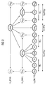
- the resources are designed as termination, for example, as a termination point TP, a cross-connection CC, a connection CON, a leased line PATH, a virtual network connection VLAN or a network element NE. They are assigned to different applications A, domains D and / or layers L.
- the resources TP, CC, CON are the Element Managers EM, the Resource CON ID the Topology Handler, the resources PATH the Network Managerment Layer NML and the Resource VLAN the Ethernet Manager ETM assigned. Furthermore, an assignment of the resources to three layers L 1 , L 2 , L 3 and two domains D A , D B is shown.
- This service can be effected by this for which the data is required.
- This service can e.g. an automatic generation or synchronization of a Topological view of the network from the perspective of Ethernet Manager ETM or a virtual network connection setup VLAN.
- the invention thus ensures that the displayed Information is always up to date, not inconsistent Intermediates come to the display, the individual components of the overall system are charged only to a small extent and thus the stability of the overall system is increased.
Landscapes
- Engineering & Computer Science (AREA)
- Computer Networks & Wireless Communication (AREA)
- Signal Processing (AREA)
- Data Exchanges In Wide-Area Networks (AREA)
Abstract
Description
In dem internationalen Standard M.3010 (02/2000) der ITU-T ist eine Referenzarchitektur eines Telecommunications Management Network (TMN) zur Überwachung und Steuerung eine Netzes für Telekommunikationsanwendungen beschrieben, bei der davon ausgegangen wird, dass das von dem TMN gesteuerte Netz unterschiedliche Typen von Netzelementen umfasst, die üblicherweise mit Hilfe von unterschiedlichen Kommunikationsmechanismen (d.h. Protokollen, Meldungen, Management Informationen - auch Objektmodell genannt) gesteuert werden.In the international standard M.3010 (02/2000) of the ITU-T is a reference architecture of Telecommunications Management Network (TMN) for monitoring and controlling a network described for telecommunications applications in which of it It is assumed that the network controlled by the TMN is different Types of network elements typically includes with the help of different communication mechanisms (i.e., logs, messages, management information - too Called object model) are controlled.
Dieses TMN umfasst folgende Funktionalitäten:
- Operations Systems Function (OSF), die das "eigentliche" Management des Telekommunikationsnetzes realisiert.
- Workstation Function (WSF), die zur Darstellung der Steuervorgänge und des Netzzustandes für einen menschlichen Anwender des TMN dient.
- Network Element Function (NEF), die eine Schnittstelle zur Steuerung der Telekommunikations-Funktionen der Netzelemente darstellt. Die Schnittstelle definiert den spezifischen Kommunikationsmechanismus des jeweiligen Netzelements, der ggf. nicht standardisiert ist. Die Summe aller Management Informationen des NE wird als Management Information Base (MIB) des NE bezeichnet. Sie wird im weiteren auch NE-MIB ganannt.
- Transformation Function (TF), die zur Verbindung von Komponenten mit unterschiedlichen Kommunikationsmechanismen und insbesondere zur Anbindung von Netzelementen, die keine standardisierte NEF aufweisen, an das TMN eingesetzt wird. Sie wird in dem Standard M.3010 (05/96) auch als Mediation Function bzw. als Q-Adaption Function bezeichnet.
- Operations Systems Function (OSF), which realizes the "actual" management of the telecommunications network.
- Workstation Function (WSF), which is used to represent the control and network state for a human user of the TMN.
- Network Element Function (NEF), which provides an interface for controlling the telecommunication functions of network elements. The interface defines the specific communication mechanism of the respective network element, which may not be standardized. The sum of all management information of the NE is referred to as the Management Information Base (MIB) of the NE. It is also known as NE-MIB.
- Transformation Function (TF), which is used to connect components with different communication mechanisms and in particular for the connection of network elements that have no standardized NEF, to the TMN. It is also referred to in the standard M.3010 (05/96) as mediation function or as Q-adaptation function.
Physikalisch ist die Funktion NEF üblicherweise in einem Netzelement (NE) angeordnet, während die Funktionen OSF und WSF üblicherweise in einem sogeanannten Operations System (OS) realisiert sind. Zwischen NE und OS kann ein Data Communication Networks (DCN) zur Übermittlung von Informationen vorgesehen sein. Die Übermittlung folgt den Prinzipien des Transportdienstes, so wie er in den unteren vier Schichten des ISO/OSI Referenzmodells im internationalen Standard X.200 beschrieben ist.Physically, the function NEF is usually in one Network element (NE) arranged, while the functions OSF and WSF usually in a so-called operations system (OS) are realized. Between NE and OS can be a data communication Networks (DCN) for the transmission of information be provided. The transmission follows the principles of Transport service, as in the lower four layers of the ISO / OSI reference model in the international standard X.200 is described.
Die einzelnen TMN Funktionen werden in zeitgemäßen TMN Systemen üblicherweise von funktionsspezifischen Programmen - auch Applikation genannt - bewirkt. Sie werden von Hardware (z.B. Prozessor, i/o Baugruppe) ausgeführt, die in den Einrichtungen vorgesehen ist. Diese Ausführung wird von Supportsoftware (z.B. Multitasking bzw. Multithreading Betriebssystem, Datenbanksystem, Windows System) unterstützt.The individual TMN functions are used in modern TMN systems usually from function-specific programs - too Application called - causes. They are replaced by hardware (e.g. Processor, i / o module) running in the facilities is provided. This implementation is supported by support software (e.g., multitasking or multithreading operating system, database system, Windows system).
Üblicherweise ist einem OS bzw. dessen Applikationen jeweils eine Vielzahl von NE zugeordnet. Dabei ist das OS meist zentral angeordnet, während die NE in dem Netz dezentral auf eine Vielzahl von Standorten verteilt sind.Usually, an OS or its applications respectively assigned to a variety of NE. The OS is usually central while the NE in the network is decentralized to one Variety of locations are distributed.
Zur Steuerung der NE eines Kommunikationsnetzes umfasst ein OS meist mehrere Managementapplikationen, von denen unterschiedliche Netztechnologien gesteuert werden. Von den einzelnen Managementapplikationen wird dabei jeweils eine, für die jeweils gesteuerte Technologie relevante, applikationsspezfische Teilmenge der Resourcen des Netzes modelliert, visualisiert und gesteuert.For controlling the NE of a communication network comprises OS mostly several management applications, of which different Network technologies are controlled. From the individual Management applications will be one, for the respective controlled technology relevant, application specific Subset of network resources modeled visualized and controlled.
Zwischen den Teilmengen bestehen Abhängigkeiten, die häufig als geschichtete Layer ausgebildet sind. Beispielsweise ist die Vermittlungsebene eines Netzes über der Übertragungsebene angeordnet. Von der Übertragungsebene werden der Vermittlungsebene Übertragungsdienste wie z.B. 2 Mbps Standleitungen zwischen Knotenpunkten des Netzes angeboten, die von der Vermittlungsebene zur Realisierung von Vermittlungsdiensten wie z.B. einfachen Telephongesprächen (POTS, Plain Old Telephone Service) oder Mehrwertdiensten (IN, Intelligent Network) genutzt werden.There are dependencies between the subsets that are common are formed as layered layers. For example the switching level of a network above the transmission level arranged. From the transmission level become the mediation level Transmission services such as e.g. 2 Mbps leased lines between nodes of the network offered by the switching plane for the realization of mediation services such as e.g. Simple Telephone Conversations (POTS, Plain Old Telephone Service) or value added services (IN, Intelligent Network) become.
Darauf aufbauend kann zum Beispiel ein Virtual Local Area Network (VLAN) Dienst zur Verbindung von mehreren, verteilten lokalen Netzen (LAN, Local Area Networks) vorgesehen werden, der dazu entweder auf einen Vermittlungs-, unmittelbar auf einen Übertragungsdienst oder auf einen Dienst einer anderen Schicht aufsetzt.Building on this, for example, a virtual local area Network (VLAN) service for connecting multiple, distributed local area networks (LANs), to do this either on a mediation, immediately on a transmission service or a service of another Layer on.
Bei einer derart geschichten Architektur werden die voneinander abhängigen Dienste in den einzelnen Schichten jeweils von unten nach oben aktiviert, so dass bei Aktivierung eines Dienstes in einer höheren Schicht der von ihm genutze Dienst der jeweils nächst tieferen Schichten bereits aktiviert und zur Nutzung bereit ist.With such a tale architecture, they become one another dependent services in each layer of each down to the top enabled, so when activating a Serving in a higher layer of the service he uses the next deeper layers already activated and ready for use.
Seitens der Managementapplikationen wird dieser Prozess dadurch unterstützt, dass zunächst der Dienst der tieferen Schicht mittels einer dieser Schicht zugeordneten ersten Managementapplikation aktiviert wird. Im Anschluss wird der Dienst von einer zweiten Managementapplikation zur Aktivierung eines Dienstes einer höheren Schicht angeboten und genutzt.On the part of the management applications this process becomes thereby that initially supports the service of the deeper Layer by means of a first management application associated with this layer is activated. Afterwards the Service from a second management application for activation offered and used a service of a higher level.
Beispielsweise werden bei einer Erweiterung des Netzes um neue, optische Übertragungsnetzelemente zunächst die neu in das Netz eingebrachten Netzelemente mit einer Applikation Element Manager EM aktiviert. Im Anschluss daran werden die aktivierten Netzelemente von einer Applikation Optical Link Manager OLM zur Aktivierung von hochbitratigen, optischen Links genutzt, die (auch) über die neuen Netzelemente führen. For example, when expanding the network to new, optical transmission network elements initially the new in the network introduced network elements with an application element Manager EM activated. Following that, the activated network elements from an application Optical Link Manager OLM for the activation of high-bit-rate, optical Links used, which lead (also) over the new network elements.
Die neuen optischen Link werden daraufhin von einer Applikation Network Management Layer NML zur Aktivierung von niederbitratigen end-to-end (e2e) Standleitungen genutzt. Die Aktivierung weiterer Dienste folgt nun demselben Muster. Beispielsweise könnten die neuen, niederbitratigen Standleitungen zur Aktivierung von Vermittlungsdiensten genutzt werden, oder die neuen hochbitratigen zur Aktivierung von VLAN Diensten.The new optical link will then be from an application Network Management Layer NML for activating low bit rate end-to-end (e2e) leased lines used. The activation Further services now follow the same pattern. For example could the new low-bit-rate leased lines used to activate brokering services, or the new high bit rate ones for activating VLAN services.
Nach dem bislang Ausgeführten wird klar, dass die Umsetzung der beschriebenen Architektur in konkrete Lösungen infolge der ausgeprägten Verteiltheit des Systems und der Vielzahl an unterschiedlichen Systemkomponenten und -anforderungen eine hochgradig komplexe technische Problemstellung darstellt.After what has been said so far, it is clear that the implementation the architecture described in concrete solutions the pronounced distribution of the system and the variety different system components and requirements represents a highly complex technical problem.
Es ist Aufgabe der Erfindung, zumindest eines der bestehenden Probleme zu erkennen und durch Angabe von zumindest einer Lehre zum technischen Handeln zu lösen.It is an object of the invention, at least one of the existing Identify problems and by specifying at least one Teaching to solve technical action.
Die Erfindung beruht auf folgenden Erkenntnissen:
- Die Aktivierung eines Dienstes einer niederen Schicht wird den zweiten Managementapplikationen der höheren Schichten üblicherweise von Hand mit Hilfe von Konfigurationskommandos mitgeteilt. Erst nach dieser Mitteilung ist der neue Dienst in der zweiten Applikation bekannt und kann ab diesem Zeitpunkt von der zweiten Applikation zur Aktivierung von Diensten der höheren Schicht angeboten und genutzt werden. Um die topologische Sicht auf ein Netz in den einzelnen Managementapplikationen zu definieren, ist deshalb erheblicher Bedienaufwand erforderlich, der zudem detaillierte Kenntnisse über den Aufbau des Netzes und die im Netz aktivierten Dienste (z.B. geschaltete Verbindungen) erfordert und fehlerträchtig ist.
- Dynamische Vorgänge im Netz wie das Hinzufügen- oder Entfernen von einzelnen Netzresourcen (z.B. Netzelemente, Baugruppen, Dienste) sind von Hand zwischen den einzelnen Applikationen zu synchronisieren. Dies erfordert neben einer hohen Disziplin bei der Erfassung der zu konfigurierenden Daten eine systematische Arbeitsweise, bei der die Änderungen zunächst aufgesammelt und erst dann weitergegeben werden, wenn eine ausreichende Anzahl von Daten und insbesondere ein passender Zeitpunkt gefunden sind. Diese Systematik reduziert zwar die Fehlerwahrscheinlichkeit bei der Konfiguration der unterschiedlichen Applikationen, macht das Gesamtsystem aber träge und schwerfällig gegenüber Änderungen.
- Die Topologie der Netzstruktur wird in zeitgemäßen Operations Systemen in jeder Managementapplikation separat eingegeben und verwaltet. Dabei ist die einzugebende Sicht abhängig sowohl von den durch eine Managementapplikation bedienbaren Technologie (z.B. einem Ausschnitt des Übertragungs- oder des Vermittlungslayers) als auch von den Konfigurationen, die im Netz mittels anderer Managementapplikationen vorgenommen werden (z.B. neue Pfade oder Netzelemente in der nächst tieferen Schicht). Wurde mit einem Managementsystem A im Netz eine neue Verbindung konfiguriert, so mussten dieses Wissen per Hand mit einzelnen Knofigurationskommandos in den Managementapplikationen eingegeben werden, die diese Verbindung als Basis für weitere Konfigurationen innerhalb ihrer Schicht verwenden.
- Um ein Kommunikationsnetz bestehend aus mehreren unterschiedlichen Technologien bedienen und steuern zu können, muss die Netzwerktopologie durch den Benutzer allen Managementapplikationen bekannt gemacht werden. Die Sicht einer Managementapplikation definiert sich dabei durch die Technologie, die mit einem System bedient werden kann.
- Von den einzelnen Applikationen werden oft räumliche begrenzte
Teile einer bestimmten Schicht gesteuert. Diese
werden auch Domäne bzw. Domain genannt. Die innerhalb einer
Domäne angeordneten physikalischen Verbindungen (Leitungen,
Kanäle) sind der Applikation meist bekannt. Dies
gilt jedoch nicht für die physikalischen Verbindungen zwischen
unterschiedlichen Domänen innerhalb einer Schicht.
Diese werden häufig von keiner der domänenspezifischen Applikationen modelliert, weil jeder dieser Applikation für eine vollständige Modellierung dieser physikalischen Interdomain-Verbindung die jeweils am anderen Ende der Verbindung liegende Netzresource der Nachbardomain fehlt. Zur vollständigen Darstellung einer e2e-Sicht dieser Schicht können Interdomain-Verbindungen beispielsweise in einer speziellen Umbrella-Applikation gespeichert werden. Im Ergebnis bedeutet dies, dass die physikalischen Verbindungen einer Schicht häufig auf eine Vielzahl von domänenspezifischen und meist zumindest eine Umbrella-Applikation verteilt sind. - Die Problematik besteht bei Diensten wie z.B. Standleitungen in vergleichbarer Weise, weil jede domänenspezifische Applikation jeweils nur einen Abschnitt des gesamten e2e-Dienstes sieht und überwacht, nicht jedoch die physikalische Interdomänen-Verbindung.
- Activation of a lower layer service is typically communicated to the second higher layer management applications by hand using configuration commands. Only after this message, the new service is known in the second application and can be offered and used by the second application to activate services of the higher layer from this point on. In order to define the topological view of a network in the individual management applications, therefore, a considerable amount of operating effort is required, which also requires detailed knowledge of the structure of the network and the services activated in the network (eg switched connections) and is error-prone.
- Dynamic processes in the network, such as the addition or removal of individual network resources (eg network elements, modules, services), must be synchronized manually between the individual applications. This requires, in addition to a high level of discipline in the acquisition of the data to be configured, a systematic procedure in which the changes are first collected and then passed on only when a sufficient number of data and in particular a suitable time have been found. Although this system reduces the probability of errors when configuring the different applications, it makes the overall system sluggish and cumbersome with respect to changes.
- The topology of the network structure is entered and managed separately in state-of-the-art operation systems in each management application. In this case, the view to be entered depends both on the technology that can be operated by a management application (for example, a section of the transmission layer or the switching layer) and on the configurations that are made in the network by means of other management applications (eg new paths or network elements in the next lower layer) ). If a new connection was configured with a management system A in the network, this knowledge had to be entered manually with individual configuration commands in the management applications that use this connection as the basis for further configurations within their layer.
- In order to operate and control a communication network consisting of several different technologies, the user has to make the network topology known to all management applications. The view of a management application is defined by the technology that can be operated with a system.
- Of the individual applications often limited space parts of a particular layer are controlled. These are also called domain or domain. The physical connections (lines, channels) arranged within a domain are usually known to the application. However, this does not apply to the physical connections between different domains within a layer.
These are often not modeled by any of the domain-specific applications because each of these applications lacks the neighboring domain network resource at the other end of the connection for a complete modeling of this physical interdomain connection. For complete representation of an e2e view of this layer, interdomain connections can be stored, for example, in a special umbrella application. As a result, this means that the physical connections of a layer are often distributed over a large number of domain-specific and usually at least one umbrella application. - The problem exists in services such as leased lines in a similar way, because each domain-specific application sees and monitors only a portion of the entire e2e service, but not the physical interdomain connection.
Eine Lösung für diese erfindungsgemäß erkannte Problemsituation sowie vorteilhafte Ausgestaltungen dieser Lösung sind in den Patentansprüchen angegeben.A solution for this inventively recognized problem situation as well as advantageous embodiments of this solution are in specified in the claims.
Mit dieser Lösung ist eine Vielzahl von Vorteilen verbunden, die in den Ausführungsbeispielen der Erfindung beschrieben werden.
- Durch das automatische Einrichten einer topologischen Sicht des Kommunikationsnetzes für die Managementapplikationen wird die physikalische Topologie des Gesamtnetzes durch den Benutzer nur ein einziges mal eingeben. Die physikalische Netztopologie wird einmal in einem zentralen Topology Handler erfasst. Die Applikationen fragen die für ihre eigenen Funktionen (z.B. topologische Sicht, Dienstaufbau) erforderlichen Daten (z.B. Interdomänen Verbindungen) bzw. die Applikationen, bei denen die erforderlichen Daten verfügbar sind (z.B. Ports, Dienste einer niedrigeren Schicht) von dem Topology Handler ab.
- Durch ein unmittelbares Mitteilen derjenigen Resourcen, die dem Topology Handler zugeordnet sind, wird vorteilhaft die Rückmeldung und erneute Abfrage durch die anfragende Applikation der Resourcen vom Topology Handler zu einem Schritt zusammengefasst.
- Das Laden der topologischen Sicht in eine Managementapplikation kann durch entsprechende Filterung der rückgemeldeten Daten flexibel in einem oder mehreren Schritten erfolgen.
- Durch Einsatz der Übertragungslayer, die durch eine Managementapplikation bedient werden können, als Basisfilter wird der Suchraum für erforderlichen Resourcen effektiv auf einen für die jeweilige Anfrage relevanten Suchraum begrenzt. Dieser Filter kann zur Steigerung der Effizient und Genauigkeit flexibel je nach Bedarf auf weitere Objekttypen erweitert werden, z.B. Netzelemente, Ports, Termination Points, physikalische und/oder logische Verbindungen, Dienste wie z.B. im Netz geschaltete Pfade und weitere logische Objekte.
- Durch Einsatz einer generischen Lösung, bei der eine Managementapplikation, die sich bei dem Topology Handler anmeldet, um die für sich erforderlichen NEs und Objekte zu laden, zugleich bekannt gibt, welche Übertragungslayer durch sie bedient werden können, wird im Topoloy Manager automatisch mit der Zeit das Wissen aufgebaut und erweitert, welche Objektinstanzen in welcher Applikation verfügbar bzw. welche Resourcen welcher Applikation zugeordnet sind.
- Für einen Netzbetreiber ergeben sich durch Reduktion der OPEX (OPerational EXpenses) wirtschaftliche Vorteile.
- Die logischen Sichten der Managementapplikationen werden dem Benutzer automatisch zur Verfügung gestellt.
- Der Benutzer muss nicht unterscheiden zwischen dem physikalischen Netz und der logischen Sicht des zu bedienenden Managementsystems.
- Der Benutzer braucht keine Kenntnis der Konfigurationenvorgänge im Netz, da die topologische Sicht der einzelnen Managementapplikationen automatisch synchronisiert wird.
- Eine Umsetzung der Erfindung erfordert keine prinzipiellen Änderungen des bisherigen Standes der Technik, sondern lässt sich nachträglich als Baustein - insbesondere als modifiziertes oder zusätzliches Computerprogrammprodukt - einfügen. Der Zeitpunkt der Realisierung kann unabhängig von anderen Funktionen gewählt werden. Bei entsprechender Entkopplung der einzelnen Schichten durch Vermeidung von bottom-up Referenzen kann das System von der untersten Ebene zu der höchsten Ebene schrittweise realisiert werden.
- By automatically setting up a topological view of the communication network for the management applications, the user will enter the physical topology of the overall network only once. The physical network topology is captured once in a central topology handler. The applications query the data required for their own functions (eg, topological view, service setup), or the applications where the required data is available (eg, ports, lower layer services) from the topology handler.
- By directly communicating those resources that are assigned to the topology handler, the feedback and retrieval by the requesting application of the resources is advantageously combined by the topology handler into a single step.
- Loading the topological view into a management application can be done flexibly in one or more steps by appropriately filtering the confirmed data.
- By using the transmission layers, which can be operated by a management application, as the basic filter, the search space for required resources is effectively limited to a search space relevant to the respective request. To increase efficiency and accuracy, this filter can be flexibly extended to other types of objects as required, eg network elements, ports, termination points, physical and / or logical connections, services such as network-connected paths and other logical objects.
- By using a generic solution, where a management application that logs in to the Topology Handler to load the NEs and objects required for it, at the same time announces which transmission layers can be served by them, in the Topoloy Manager automatically with the time The knowledge is built up and extended, which object instances are available in which application or which resources are assigned to which application.
- For a network operator, the reduction of OPEX (OPerational EXpenses) results in economic benefits.
- The logical views of the management applications are automatically made available to the user.
- The user does not have to differentiate between the physical network and the logical view of the management system to be operated.
- The user does not need to know the configuration processes in the network because the topological view of the individual management applications is automatically synchronized.
- An implementation of the invention requires no fundamental changes of the prior art, but can be subsequently added as a module - especially as a modified or additional computer program product. The time of realization can be chosen independently of other functions. With appropriate decoupling of the individual layers by avoiding bottom-up references, the system can be realized step-by-step from the lowest level to the highest level.
Die Erfindung wird im Folgenden anhand von weiteren Ausführungsbeispielen, die auch in den Figuren dargestellt sind, erläutert. Es sei betont, dass die aufgezeigten Ausführungen der Erfindung trotz ihrer teilweise sehr detailgetreuen Darstellung lediglich beispielhafter Natur und nicht einschränkend zu verstehen sind. Es zeigen:
- Figur
- 1 eine beispielhafte Anordnung, umfassend ein zentrales Operations System OS mit Applikationen A zur Steuerung von dezentralen Elementen NE eines Kommunikationsnetzes KN
- Figur 2
- eine bespielhafte Zuordnung von Resourcen NE, TP, CC, CON, PATH, VLAN des Kommunikationsneztes KN zu Applikationen A sowie Beziehungen zwischen diesen Resourcen
- Figuren 3-7
- einen beispielhaften Ablauf der Erfindung in einer nach den vorstehenden Figuren ausgebildeten Ablaufumgebung
- figure
- 1 shows an exemplary arrangement comprising a central operations system OS with applications A for controlling decentralized elements NE of a communication network KN
- FIG. 2
- an exemplary assignment of resources NE, TP, CC, CON, PATH, VLAN of the communications network KN to applications A as well as relationships between these resources
- Figures 3-7
- an exemplary sequence of the invention in a trained according to the preceding figures runtime environment
Die Ausführungsbeispiele werden anhand der in Figur 1 dargestellten Anordnung erklärt. Diese Anordnung umfasst ein zentrales Operations System OS mit Applikationen A zur Steuerung von dezentralen Elementen NE eines Kommunikationsnetzes KN, die insbesondere als Topology Handler TPG, Optical Link Manager OML, Network Management Layer NML, Ethernet Manager ETM oder Element Manager EMA, EMB ausgebildet sind. Den als Applikationen A ausgebildeten Erzeugnissen können die TMN Funktionsblöcke Operations Systems Function und Workstation Function, den als Netzelemente NE ausgebildeten Erzeugnissen der TMN Funktionsblock Network Element Function zugeordnet sein. Die Applikationen A sind untereinander durch ein Datennetz COB verbunden. Das Operations System OS und die Netzelemente NE sind durch ein in der Fachwelt als Data Communication Network (DCN) bezeichnetes Datennetz verbunden. Die Erzeugnisse umfassen Hardware - insbesondere Prozessoren und Speichermittel - zur Durchführung von Computerprogrammprodukten P, mit denen die Funktionen realisiert sind.The embodiments will be explained with reference to the arrangement shown in FIG. This arrangement comprises a central operations system OS with applications A for controlling decentralized elements NE of a communication network KN, which are designed in particular as Topology Handlers TPG, Optical Link Manager OML, Network Management Layer NML, Ethernet Manager ETM or Element Manager EM A , EM B are. The products designed as applications A, the TMN function blocks Operations Systems Function and Workstation Function, which are designed as network elements NE products of the TMN function block Network Element Function be assigned. The applications A are interconnected by a data network COB. The operations system OS and the network elements NE are connected by a data network referred to in the art as Data Communication Network (DCN). The products comprise hardware - in particular processors and memory means - for the execution of computer program products P, with which the functions are realized.
In Figur 2 sind einige, typische Resourcen eines zeitgemäßen Kommunikationsnetzes KN aufgezeigt. Die Resourcen sind als Termination beispielsweise als Termination Point TP, Cross Connection CC, Connection CON, Standleitung PATH, virtuelle Netzverbindung VLAN oder als Netzelement NE ausgebildet. Sie sind unterschiedlichen Applikationen A, Domänen D und/oder Schichten L zugeordnet. Die Resourcen TP, CC, CON sind den Element Managern EM, die Resource CONID dem Topology Handler, die Resourcen PATH dem Network Managerment Layer NML und die Resource VLAN dem Ethernet Manager ETM zugeordnet. Weiterhin ist eine Zuordnung der Resourcen zu drei Schichten L1, L2, L3 und zwei Domänen DA, DB dargestellt.FIG. 2 shows some typical resources of a state-of-the-art communications network KN. The resources are designed as termination, for example, as a termination point TP, a cross-connection CC, a connection CON, a leased line PATH, a virtual network connection VLAN or a network element NE. They are assigned to different applications A, domains D and / or layers L. The resources TP, CC, CON are the Element Managers EM, the Resource CON ID the Topology Handler, the resources PATH the Network Managerment Layer NML and the Resource VLAN the Ethernet Manager ETM assigned. Furthermore, an assignment of the resources to three layers L 1 , L 2 , L 3 and two domains D A , D B is shown.
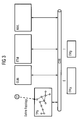
In den Figuren 3-7 ist eine Ausführungsvariante der Erfindung mit einer gestuften Abfrage durch die Applikation Ethernet Manager ETM dargestellt. Die einzelnen Verfahrensschritte sind mit Hilfe von Pfeilen visualisiert, die für folgende Schritte repräsentativ sind:
- Figur 3
- Zunächst wird die Topologie des Kommunikationsnetzes KN einmal im Topology Handler TPG erfasst. Dies kann beispielsweise durch die dargestellte einmalige, manuelle Konfiguration durch den Netzbetreiber erfolgen. Alternativ kann die Topologie auch automatisch von den Applikationen A abgefragt werden. Insbesondere kann diese Abfrage schrittweise bewirkt werden, beispielsweise indem dem Topology Handler TPG von den Applikationen A bei einer Anfrage an den Topology Handler TPG oder einer erstmaligen Registrierung beim Topology Handler TPG die der Applikation A zugeordneten Resourcen mitgeteilt werden.
- Figur 4
- Sodann werden die für die Applikation ETM erforderlichen
Netzelemente NE am Topology Handler TPG abgefragt,
von dem an die abfragende Applikationen ETM
eine gefilterte Liste von Netzelementen NE zurückgeliefert
wird.
Vorteilhaft werden für e2e Applikationen Übertragungslayer als Filter für den Aufbau der topologischen Netzsicht eingesetzt. Zur Steigerung der Ef- fizient und Genauigkeit kann der Filter flexibel je nach Bedarf auf weitere Objekttypen erweitert werden, z.B. Netzelemente NE, Ports, Termination Points TP, physikalische Verbindungen CON oder Dienste wie z.B. im Netz geschaltete Standleitungen PATH und weitere logische Objekte wie z.B. virtuelle Netzverbindungen VLAN.
Vorteilhaft werden die Filter so gewählt, dass genau diejenigen Resourcen mitgeteilt werden, die für die Bearbeitung der angefragten Daten durch die anfragende Applikation A erforderlich sind. Dies kann beispielsweise durch eine entsprechend klare Anfrage der Applikation A bewirkt werden, oder durch Berücksichtigung eines entsprechenden, speziellen Wissens des Topology Handlers TPG über das Umfeld der anfragenden Applikation A. - Figur 5
- Von den für das Management der in diese Liste angegebenen Netzelemente NE zuständigen Element Managern EM werden die Resourcen abgefragt.
- Figur 6
- Als Antwort werden die von den Element Managern EM werden die Resoucen bzw. die sie repräsentierenden Objektinstanzen/NE-Objekte mitgeteilt.
- Figur 7
- Im Anschluss werden Verbindungen, insbesondere physikalische
Verbindungen CONID oder logische Verbindungen
bzw. Standleitungen PATH am Topology Handler
TPG angefordert.
Entspricht die angeforderte Verbindung einer ihm zugeordneten, physikalischen Verbindung CONID, bedient der Topology Handler TPG diese Anfrage unmittelbar, beispielsweise indem die dem Topology Handler TPG zugeordnete Resource CONID mitgeteilt wird.
Handelt es sich um einen logischen Übertragungslayer, gibt der Topology Handler TPG die Information zurück, von welcher Applikation A die angefragten Daten anzufordern sind. Die anfragende Managementapplikation ETM holt sich in diesem Fall die erforderlichen Daten von der mitgeteilten Managementapplikation A (Objektinstanz).
- FIG. 3
- First, the topology of the communication network KN is recorded once in the Topology Handler TPG. This can be done for example by the illustrated one-time, manual configuration by the network operator. Alternatively, the topology can also be queried automatically by the applications A. In particular, this query can be effected step by step, for example by informing the topology handler TPG of the applications A of a request to the topology handler TPG or a first registration with the topology handler TPG the resources assigned to the application A.
- FIG. 4
- The network elements NE required for the application ETM are then queried on the topology handler TPG, from which a filtered list of network elements NE is returned to the querying applications ETM.
Advantageously, transmission layers are used as filters for the construction of the topological network view for e2e applications. To increase the efficiency and accuracy of the filter can be flexibly expanded as needed to other types of objects, such as network elements NE, ports, Termination Points TP, physical connections CON or services such as network-connected leased lines PATH and other logical objects such as virtual Network connections VLAN.
Advantageously, the filters are chosen so that exactly those resources are communicated that are required for the processing of the requested data by the requesting application A. This can be effected for example by a correspondingly clear request of the application A, or by taking into account a corresponding, specific knowledge of the topology handler TPG about the environment of the requesting application A. - FIG. 5
- The resources responsible for managing the network elements NE responsible for the management of the network elements NE listed in this list are queried.
- FIG. 6
- In response, the element managers EM will report the resources or the object instances / NE objects representing them.
- FIG. 7
- Subsequently, connections, in particular physical connections CON ID or logical connections or leased lines PATH, are requested at Topology Handler TPG.
If the requested connection corresponds to a physical connection CON ID assigned to it, the topology handler TPG directly services this request, for example by notifying the resource CON ID assigned to the topology handler TPG.
If it is a logical transmission layer, the topology handler TPG returns the information of which application A the requested data is to be requested. In this case, the requesting management application ETM retrieves the required data from the notified management application A (object instance).
Sobald der Applikation Ethernet Manager ETM alle erforderlichen Daten vorliegen, kann von dieser der Dienst bewirkt werden, für den die Daten erforderlich sind. Dieser Dienst kann z.B. eine automatische Generierung bzw. Synchronisation einer topologischen Sicht des Netzes aus dem Blickwinkel des Ethernet Managers ETM sein oder ein Aufbau einer virtuellen Netzverbindung VLAN.Once the application Ethernet Manager ETM all required Data is available, the service can be effected by this for which the data is required. This service can e.g. an automatic generation or synchronization of a Topological view of the network from the perspective of Ethernet Manager ETM or a virtual network connection setup VLAN.
Selbstverständlich können die aufgezeigten Schritte auch mit einer einzigen Anfrage bewirkt werden. Die gewählte Realisierungsvariante hängt von den individuellen Anforderungen der jeweiligen Applikation A ab. Wenn beispielsweise schnelle Reaktionszeiten wichtig sind, wird man eher zu einer schrittweisen Realisierung neigen, weil dann pro Schritt weniger Aufgaben auf einmal bewirkt werden müssen. Wenn man hingegen möglichst von Anfang an vollständige Informationen besitzen möchte, werden die erforderlichen Daten eher in einem einzigen Schritt abfragt, weil dann die granulare Abfragetechnik nicht erforderlich ist.Of course, the steps shown also with a single request. The chosen implementation variant depends on the individual requirements of the respective application A from. For example, if fast reaction times important, you become more of a gradual one Realization, because then less per step Tasks have to be done at once. If you are against it have complete information as possible from the beginning would like to be, the required data rather in a single Queries step, because then the granular query technique is not required.
Durch die Erfindung wird ein generischer Weg aufgezeigt, wie die topologische Netzsicht in einem verteilten System für das Management von Kommunikationsnetzen durch e2e Applikationen OML, ETM, NML automatisch erkannt und synchronisiert werden kann. Dabei müssen wegen der Verwendung einer zentralen Komponente für die Definition des physikalischen Netzes (Topology Handler TPG) die restlichen Komponenten bzw. Applikationen A des verteilten Operations Systems OS kein Wissen über andere Komponenten bzw. Applikationen A haben. By the invention, a generic way is shown how the topological network view in a distributed system for the Management of communication networks through e2e applications OML, ETM, NML are automatically detected and synchronized can. It must because of the use of a central component for the definition of the physical network (Topology Handler TPG) the remaining components or applications A of the distributed operations system OS no knowledge about others Components or applications A have.
Mit der Erfindung wird somit sichergestellt, dass die angezeigten Informationen immer aktuell sind, keine inkonsistenten Zwischenstände zur Anzeige kommen, die einzelnen Komponenten des Gesamtsystems nur in geringem Maße belastet werden und damit die Stabilität des Gesamtsystems erhöht wird.The invention thus ensures that the displayed Information is always up to date, not inconsistent Intermediates come to the display, the individual components of the overall system are charged only to a small extent and thus the stability of the overall system is increased.
Abschließend sei darauf hingewiesen, dass die Beschreibung der für die Erfindung relevanten Komponenten des Systems grundsätzlich nicht einschränkend in Hinblick auf eine bestimmte physikalische Realisierung oder Zuordnung zu verstehen ist. Für einen einschlägigen Fachmann ist insbesondere offensichtlich, dass alle Erzeugnisse teilweise oder vollständig in Software / Computerprogrammprodukten und/oder über mehrere physikalische Einrichtungen verteilt realisiert werden können.Finally, it should be noted that the description the relevant components of the system of the invention basically not restrictive with regard to a particular physical realization or assignment to understand is. In particular, for a person skilled in the art obviously that all products partially or completely in software / computer program products and / or over several physical facilities are distributed can.
Claims (9)
bei dem die Kopplung bei Zugriff einer Applikation auf ihr nicht zugeordnete Resourcen mit folgenden Schritten erfolgt:
in which the coupling occurs when an application accesses its unassigned resources with the following steps:
Priority Applications (2)
| Application Number | Priority Date | Filing Date | Title |
|---|---|---|---|
| EP04012938A EP1603271A1 (en) | 2004-06-01 | 2004-06-01 | Topology handler |
| US11/142,717 US20060028985A1 (en) | 2004-06-01 | 2005-06-01 | Topology handler |
Applications Claiming Priority (1)
| Application Number | Priority Date | Filing Date | Title |
|---|---|---|---|
| EP04012938A EP1603271A1 (en) | 2004-06-01 | 2004-06-01 | Topology handler |
Publications (1)
| Publication Number | Publication Date |
|---|---|
| EP1603271A1 true EP1603271A1 (en) | 2005-12-07 |
Family
ID=34925206
Family Applications (1)
| Application Number | Title | Priority Date | Filing Date |
|---|---|---|---|
| EP04012938A Withdrawn EP1603271A1 (en) | 2004-06-01 | 2004-06-01 | Topology handler |
Country Status (2)
| Country | Link |
|---|---|
| US (1) | US20060028985A1 (en) |
| EP (1) | EP1603271A1 (en) |
Cited By (1)
| Publication number | Priority date | Publication date | Assignee | Title |
|---|---|---|---|---|
| EP1921806A1 (en) * | 2006-09-26 | 2008-05-14 | Nokia Siemens Networks Gmbh & Co. Kg | Method for managing network resource usage |
Families Citing this family (1)
| Publication number | Priority date | Publication date | Assignee | Title |
|---|---|---|---|---|
| US9401432B2 (en) * | 2014-01-16 | 2016-07-26 | Semiconductor Energy Laboratory Co., Ltd. | Semiconductor device and electronic device |
Citations (2)
| Publication number | Priority date | Publication date | Assignee | Title |
|---|---|---|---|---|
| US5726979A (en) * | 1996-02-22 | 1998-03-10 | Mci Corporation | Network management system |
| US20030189919A1 (en) * | 2002-04-08 | 2003-10-09 | Sanyogita Gupta | Determining and provisioning paths within a network of communication elements |
Family Cites Families (1)
| Publication number | Priority date | Publication date | Assignee | Title |
|---|---|---|---|---|
| US5748892A (en) * | 1996-03-25 | 1998-05-05 | Citrix Systems, Inc. | Method and apparatus for client managed flow control on a limited memory computer system |
-
2004
- 2004-06-01 EP EP04012938A patent/EP1603271A1/en not_active Withdrawn
-
2005
- 2005-06-01 US US11/142,717 patent/US20060028985A1/en not_active Abandoned
Patent Citations (2)
| Publication number | Priority date | Publication date | Assignee | Title |
|---|---|---|---|---|
| US5726979A (en) * | 1996-02-22 | 1998-03-10 | Mci Corporation | Network management system |
| US20030189919A1 (en) * | 2002-04-08 | 2003-10-09 | Sanyogita Gupta | Determining and provisioning paths within a network of communication elements |
Non-Patent Citations (2)
| Title |
|---|
| DASGUPTA P ED - INSTITUTE OF ELECTRICAL AND ELECTRONICS ENGINEERS: "Agent based peer-to-peer systems", THE 2002 45TH. MIDWEST SYMPOSIUM ON CIRCUITS AND SYSTEMS. CONFERENCE PROCEEDINGS. TULSA, OK, AUG. 4 - 7, 2002, MIDWEST SYMPOSIUM ON CIRCUITS AND SYSTEMS, NEW YORK, NY : IEEE, US, vol. VOL. 1 OF 3, 4 August 2002 (2002-08-04), pages 663 - 666, XP010635301, ISBN: 0-7803-7523-8 * |
| MISCHKE J ET AL: "A METHODOLOGY FOR THE DESIGN OF DISTRIBUTED SEARCH IN P2P MIDDLEWARE", IEEE NETWORK, IEEE INC. NEW YORK, US, vol. 18, no. 1, January 2004 (2004-01-01), pages 30 - 37, XP001047732, ISSN: 0890-8044 * |
Cited By (1)
| Publication number | Priority date | Publication date | Assignee | Title |
|---|---|---|---|---|
| EP1921806A1 (en) * | 2006-09-26 | 2008-05-14 | Nokia Siemens Networks Gmbh & Co. Kg | Method for managing network resource usage |
Also Published As
| Publication number | Publication date |
|---|---|
| US20060028985A1 (en) | 2006-02-09 |
Similar Documents
| Publication | Publication Date | Title |
|---|---|---|
| DE60116178T2 (en) | Root cause analysis in a distributed network management architecture | |
| EP0973342B1 (en) | Method and communication system for processing alarms in a network with several management layers | |
| EP1034639B1 (en) | Method and communication system for processing alarms in a management network with several management levels | |
| DE69927929T2 (en) | Method and system for network management | |
| DE60129480T2 (en) | TECHNOLOGY FOR DETERMINING CONNECTIVITY SOLUTIONS FOR NETWORK ELEMENTS | |
| DE69821243T2 (en) | RECONFIGURATION OF A CELLULAR TELEPHONE NETWORK | |
| EP1955480B1 (en) | Network having redundancy properties, ethernet switch for such a network, and method for configuring such a network | |
| DE19801785C2 (en) | Process and communication system for handling alarms through a management network with multiple management levels | |
| DE112012003778T5 (en) | Computer network management tools | |
| EP1794946B1 (en) | Self-adapting bandwidth management | |
| EP1152625A1 (en) | Updating of manufacturer specific harware informations at the manufacturer independent OMC-NMC interface of a mobile radio network | |
| EP1668822B1 (en) | Method for synchronizing alarms in a management system of a communications network | |
| EP1206883B1 (en) | Generic alignment method in a multi-manager environment | |
| EP1624614B1 (en) | Automatic planning of network configurations | |
| DE102005027977A1 (en) | System and method for high capacity error correlation | |
| EP1603271A1 (en) | Topology handler | |
| DE69932302T2 (en) | Apparatus and method for exploring traces in a communication network | |
| EP1730886B1 (en) | Method and devices for distributing management information in a management network of a communications system | |
| DE69838373T2 (en) | State machine for a track management system | |
| DE69910570T2 (en) | PROGRAMMING CALL PROCESSING APPLICATIONS IN A COMMUNICATION SYSTEM | |
| DE60207842T2 (en) | Simplified control unit of a communication network element for handling both SDH and OTH signals | |
| EP1145538B1 (en) | Method and communication system for processing state information in a management network having different management levels | |
| EP1460798B1 (en) | Method and communication system to cancel management operations in a management network | |
| DE10163533A1 (en) | Persistent storage of network management data using object references | |
| DE102008063276A1 (en) | Method for installing software-update in e.g. controller integrated system in motor vehicle in automotive industry, involves analyzing behavior of entire system, and implementing update after positive evaluation of system behavior |
Legal Events
| Date | Code | Title | Description |
|---|---|---|---|
| PUAI | Public reference made under article 153(3) epc to a published international application that has entered the european phase |
Free format text: ORIGINAL CODE: 0009012 |
|
| AK | Designated contracting states |
Kind code of ref document: A1 Designated state(s): AT BE BG CH CY CZ DE DK EE ES FI FR GB GR HU IE IT LI LU MC NL PL PT RO SE SI SK TR |
|
| AX | Request for extension of the european patent |
Extension state: AL HR LT LV MK |
|
| 17P | Request for examination filed |
Effective date: 20060522 |
|
| AKX | Designation fees paid |
Designated state(s): AT CH DE ES FR GB LI |
|
| RAP1 | Party data changed (applicant data changed or rights of an application transferred) |
Owner name: NOKIA SIEMENS NETWORKS GMBH & CO. KG |
|
| RAP3 | Party data changed (applicant data changed or rights of an application transferred) |
Owner name: NOKIA SIEMENS NETWORKS S.P.A. |
|
| RAP3 | Party data changed (applicant data changed or rights of an application transferred) |
Owner name: NOKIA SIEMENS NETWORKS GMBH & CO. KG |
|
| 17Q | First examination report despatched |
Effective date: 20080609 |
|
| STAA | Information on the status of an ep patent application or granted ep patent |
Free format text: STATUS: THE APPLICATION IS DEEMED TO BE WITHDRAWN |
|
| 18D | Application deemed to be withdrawn |
Effective date: 20081021 |