EP1598263A2 - Bicycle headset structure - Google Patents
Bicycle headset structure Download PDFInfo
- Publication number
- EP1598263A2 EP1598263A2 EP04030301A EP04030301A EP1598263A2 EP 1598263 A2 EP1598263 A2 EP 1598263A2 EP 04030301 A EP04030301 A EP 04030301A EP 04030301 A EP04030301 A EP 04030301A EP 1598263 A2 EP1598263 A2 EP 1598263A2
- Authority
- EP
- European Patent Office
- Prior art keywords
- bicycle
- handlebar
- steerer tube
- tubular spacer
- spacer member
- Prior art date
- Legal status (The legal status is an assumption and is not a legal conclusion. Google has not performed a legal analysis and makes no representation as to the accuracy of the status listed.)
- Granted
Links
- 125000006850 spacer group Chemical group 0.000 claims abstract description 46
- 230000002093 peripheral effect Effects 0.000 claims description 2
- 230000036961 partial effect Effects 0.000 description 3
- 230000001681 protective effect Effects 0.000 description 2
- 239000000725 suspension Substances 0.000 description 2
- 230000002860 competitive effect Effects 0.000 description 1
- 239000004020 conductor Substances 0.000 description 1
- 238000004519 manufacturing process Methods 0.000 description 1
- 239000000463 material Substances 0.000 description 1
- 239000007769 metal material Substances 0.000 description 1
- 238000012986 modification Methods 0.000 description 1
- 230000004048 modification Effects 0.000 description 1
Images

Classifications
-
- B—PERFORMING OPERATIONS; TRANSPORTING
- B62—LAND VEHICLES FOR TRAVELLING OTHERWISE THAN ON RAILS
- B62K—CYCLES; CYCLE FRAMES; CYCLE STEERING DEVICES; RIDER-OPERATED TERMINAL CONTROLS SPECIALLY ADAPTED FOR CYCLES; CYCLE AXLE SUSPENSIONS; CYCLE SIDE-CARS, FORECARS, OR THE LIKE
- B62K21/00—Steering devices
- B62K21/12—Handlebars; Handlebar stems
-
- B—PERFORMING OPERATIONS; TRANSPORTING
- B62—LAND VEHICLES FOR TRAVELLING OTHERWISE THAN ON RAILS
- B62J—CYCLE SADDLES OR SEATS; AUXILIARY DEVICES OR ACCESSORIES SPECIALLY ADAPTED TO CYCLES AND NOT OTHERWISE PROVIDED FOR, e.g. ARTICLE CARRIERS OR CYCLE PROTECTORS
- B62J11/00—Supporting arrangements specially adapted for fastening specific devices to cycles, e.g. supports for attaching maps
- B62J11/10—Supporting arrangements specially adapted for fastening specific devices to cycles, e.g. supports for attaching maps for mechanical cables, hoses, pipes or electric wires, e.g. cable guides
- B62J11/19—Supporting arrangements specially adapted for fastening specific devices to cycles, e.g. supports for attaching maps for mechanical cables, hoses, pipes or electric wires, e.g. cable guides specially adapted for electric wires
-
- B—PERFORMING OPERATIONS; TRANSPORTING
- B62—LAND VEHICLES FOR TRAVELLING OTHERWISE THAN ON RAILS
- B62J—CYCLE SADDLES OR SEATS; AUXILIARY DEVICES OR ACCESSORIES SPECIALLY ADAPTED TO CYCLES AND NOT OTHERWISE PROVIDED FOR, e.g. ARTICLE CARRIERS OR CYCLE PROTECTORS
- B62J45/00—Electrical equipment arrangements specially adapted for use as accessories on cycles, not otherwise provided for
- B62J45/20—Cycle computers as cycle accessories
-
- B—PERFORMING OPERATIONS; TRANSPORTING
- B62—LAND VEHICLES FOR TRAVELLING OTHERWISE THAN ON RAILS
- B62K—CYCLES; CYCLE FRAMES; CYCLE STEERING DEVICES; RIDER-OPERATED TERMINAL CONTROLS SPECIALLY ADAPTED FOR CYCLES; CYCLE AXLE SUSPENSIONS; CYCLE SIDE-CARS, FORECARS, OR THE LIKE
- B62K19/00—Cycle frames
- B62K19/30—Frame parts shaped to receive other cycle parts or accessories
- B62K19/40—Frame parts shaped to receive other cycle parts or accessories for attaching accessories, e.g. article carriers, lamps
-
- B—PERFORMING OPERATIONS; TRANSPORTING
- B62—LAND VEHICLES FOR TRAVELLING OTHERWISE THAN ON RAILS
- B62K—CYCLES; CYCLE FRAMES; CYCLE STEERING DEVICES; RIDER-OPERATED TERMINAL CONTROLS SPECIALLY ADAPTED FOR CYCLES; CYCLE AXLE SUSPENSIONS; CYCLE SIDE-CARS, FORECARS, OR THE LIKE
- B62K21/00—Steering devices
- B62K21/06—Bearings specially adapted for steering heads
-
- B—PERFORMING OPERATIONS; TRANSPORTING
- B62—LAND VEHICLES FOR TRAVELLING OTHERWISE THAN ON RAILS
- B62M—RIDER PROPULSION OF WHEELED VEHICLES OR SLEDGES; POWERED PROPULSION OF SLEDGES OR SINGLE-TRACK CYCLES; TRANSMISSIONS SPECIALLY ADAPTED FOR SUCH VEHICLES
- B62M25/00—Actuators for gearing speed-change mechanisms specially adapted for cycles
- B62M25/02—Actuators for gearing speed-change mechanisms specially adapted for cycles with mechanical transmitting systems, e.g. cables, levers
-
- B—PERFORMING OPERATIONS; TRANSPORTING
- B62—LAND VEHICLES FOR TRAVELLING OTHERWISE THAN ON RAILS
- B62M—RIDER PROPULSION OF WHEELED VEHICLES OR SLEDGES; POWERED PROPULSION OF SLEDGES OR SINGLE-TRACK CYCLES; TRANSMISSIONS SPECIALLY ADAPTED FOR SUCH VEHICLES
- B62M25/00—Actuators for gearing speed-change mechanisms specially adapted for cycles
- B62M25/08—Actuators for gearing speed-change mechanisms specially adapted for cycles with electrical or fluid transmitting systems
Definitions
- This invention generally relates to a bicycle headset structure for a bicycle. More specifically, the present invention relates to a bicycle headset structure configured to provide a wiring channel from a handlebar attachment member to a bicycle frame portion such that a wire can extend through a head tube of a bicycle frame in a concealed manner.
- Bicycling is becoming an increasingly more popular form of recreation as well as a means of transportation. Moreover, bicycling has become a very popular competitive sport for both amateurs and professionals. Whether the bicycle is used for recreation, transportation or competition, the bicycle industry is constantly improving the various components of the bicycle as well as the frame of the bicycle.
- bicycles have been equipped with electrical components to make riding easier and more enjoyable for the rider.
- Some bicycles are equipped with computer controlled components. For example, many new bicycles have automatic shifting units that are automatically adjusted according to the riding conditions by a cycle computer or control unit. Also, some bicycles have automatic suspensions that are automatically adjusted according to the riding conditions by a cycle computer or control unit.
- these bicycles with electrical components need to be equipped with control devices for controlling the various electrical components and one or more batteries for supplying electrical power to the various electrical components.
- control devices for controlling the various electrical components and one or more batteries for supplying electrical power to the various electrical components.
- these electronic components are preferably mounted in particular areas of the bicycle such as the handlebar, which further limits the mounting areas for the electronic components.
- mount the electronic components in such a manner as to be attractive and easy to use.
- One object of certain embodiments of the present invention is to provide a bicycle headset structure that is configured provide an unobstructed passageway or channel through the head tube of the bicycle frame for passing wires from components mounted in the handlebar area to components mounted on the rest of the bicycle.
- Another object of certain embodiments of the present invention is to provide a bicycle headset structure that is relatively inexpensive to manufacture and relatively simple to install.
- a bicycle headset structure that basically comprises a handlebar attachment member and a tubular spacer member.
- the handlebar attachment member has a handlebar mounting portion configured to secure a bicycle handlebar thereto and a steerer tube attachment portion configured to secure a bicycle steerer tube thereto.
- a wiring passage extends between the handlebar mounting portion and the steerer tube attachment portion.
- the tubular spacer member has a first end with an upper end opening, a second end with a lower end opening, a wiring channel extending between the first and second ends of the tubular spacer member and an axial passageway extending axially between the upper and lower end openings of the tubular spacer member.
- the axial passageway is dimensioned to receive the bicycle steerer tube.
- the wiring channel is arranged to communicate with the wiring passage of handlebar attachment member when the handlebar attachment member and the tubular spacer member are attached to the bicycle steerer tube.
- the foregoing objects can also basically be attained by providing a tubular spacer member for use in a bicycle headset structure disposed under a handlebar attachment member.
- the tubular spacer member basically comprises a first end portion, a second end portion, a central passageway, and a wiring channel.
- the first end portion is provided with an upper end opening.
- the second end portion is provided with a lower end opening.
- the central passageway extends axially between the upper and lower end openings and is dimensioned to receive a bicycle steerer tube therein.
- the wiring channel extends from one of the upper and lower end openings towards the other one of the upper and lower end openings.
- the wiring channel is arranged to form a space outside of an outer peripheral surface of the bicycle steerer tube when the tubular spacer member is attached to the bicycle steerer tube.
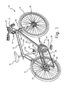
- Figure 1 is a rear side perspective view of a bicycle that is equipped with a bicycle headset structure in accordance with one embodiment of the present invention
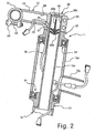
- Figure 2 is an enlarged, partial side cross-sectional view of a top portion of the bicycle headset structure illustrated in Figure 1 in accordance with the present invention
- Figure 3 is a partial top perspective view of a front portion of the bicycle illustrated in Figures 1 and 2, which further illustrates the bicycle headset structure in accordance with the present invention
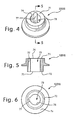
- Figure 4 is a top perspective view of the tubular spacer member of the bicycle headset structure illustrated in Figures 1-3 in accordance with the present invention
- Figure 5 is a longitudinal cross-sectional view of the tubular spacer member of the bicycle headset structure illustrated in Figures 1-4 as seen along section line 5-5 in accordance with the present invention
- Figure 6 is a bottom plan view of the bottom end opening of the tubular spacer member of the bicycle headset structure illustrated in Figures 1-5 in accordance with the present invention
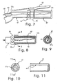
- Figure 7 is an enlarged, partial top view of the right portion of the handlebar utilizing the present invention.
- Figure 8 is a side view of the right end portion handlebar with selected portions shown in longitudinal cross section;
- Figure 9 is a transverse cross section of the right end portion handlebar as seen along section line 9-9 of Figure 8;
- Figure 10 is an end elevational view of the right hand grip used with the present invention.
- Figure 11 is a longitudinal cross section of the right hand grip shown in Figures 7-10 in accordance with the present invention.
- a bicycle 10 is illustrated that is equipped with a bicycle headset structure 11 and various electronic components in such a manner as to carryout a first embodiment of the present invention as discussed below.
- the following directional terms "forward, rearward, above, downward, vertical, horizontal, below and transverse" as well as any other similar directional terms refer to those directions of a bicycle equipped with the present invention. Accordingly, these terms, as utilized to describe the present invention should be interpreted relative to a bicycle equipped with the present invention.
- the bicycle 10 basically includes a main frame 12, a rear chain stay 13, a front wheel 14 and a rear wheel 15.
- the main frame 12 is also equipped with a seat 16, a handlebar 17 and a front fork 18 that rotatably supports the front wheel 14 via a front dynamo hub 19 of the front wheel 14.
- the front wheel 14 is rotatably mounted to the front fork 18 by the front dynamo hub 19 in conventional manner.
- the main frame 12 basically includes a top tube 12a, a seat tube 12b, a down tube 12c and a head tube 12d.
- the rear wheel 15 is rotatably mounted to the rear chain stay 13, which in turn is coupled to the main frame 12 at the bottom bracket.
- an upper end of the front fork 18 is movably coupled to the head tube 12d of the main frame 12, while the lower end of the front fork 18 is coupled to the axle of the front dynamo hub 19.
- the front fork 18 basically includes a steerer tube 18a that is rotatably mounted in the head tube 12d of the main frame 12 by the bicycle headset structure 11.
- the handlebar 17 is fixed to the front fork 18 for turning the front fork 18 and the front wheel 14 relative to the main frame 12.
- the bicycle 10 further includes a drive train 21 that basically includes a plurality of front chain rings or sprockets 22 mounted on a bottom bracket (not shown), a pair of crank arms 23 with a pair of pedals 24, an electric front derailleur 25 mounted on the bottom bracket (not shown), a drive chain 26, a plurality of rear sprockets 27 coupled to a rear hub 28 of the rear wheel 15 in a conventional manner, and an electric rear derailleur 29 mounted to the rear chain stay 13. Since these parts of bicycle 10 are well known in the art, these parts will not be discussed or illustrated in detail herein, except as they are modified to be used in conjunction with the present invention. Moreover, various conventional bicycle parts such as brakes, etc., which are not illustrated and/or discussed herein, are also used in conjunction with the present invention as needed and/or desired.
- the bicycle 10 is equipped with various electronic control components that are mounted on the handlebar 17.
- the bicycle 10 is equipped with a cycle computer 31, a front electronic shifter 32 and a rear electronic shifter 33.
- the cycle computer 31 is electrically coupled to various electronic components including, but not limited to, the front dynamo hub 19, the front electronic shifter 32 and the rear electronic shifter 33.
- the bicycle 10 can be equipped with front and/or rear electric dampening suspensions that can be electrically coupled to cycle computer 31.
- the cycle computer 31 is preferably electrically coupled to these various electronic components by a main electrical cable or cord 41 that splits into several feed wires or cords (only two electrical cords will be illustrated in Figure 2 for the sake of simplicity and for easy of illustration) and a pair of electrical shift cables or cords 42 and 43.
- the cords 41, 42 and 43 are multiconductor cords that each includes a plurality of electrical conductors. Examples of various electronic control components that can be used with the present invention are the Nexave C-910 components that are sold by Shimano Inc.
- the cycle computer 31 includes a plurality of push buttons for operating the automatic shifting control.
- the cycle computer 31 is electrically coupled to the electric deraille 25 and 29 by the main electrical cable or cord 41, while the cycle computer 31 is electrically coupled to the electronic shifters 32 and 33 by the electrical shift cords 42 and 43, respectively.
- the cycle computer 31 is preferably configured and arranged with control programs stored for controlling the automatic shifting based on the rider input commands and/or riding conditions from sensors (not shown).
- the cycle computer 31 preferably includes a microcomputer with a control program that controls the automatic shifting control.
- the cycle computer 31 can also include other conventional components such as an input interface circuit, an output interface circuit, and storage devices such as a ROM (Read Only Memory) device and a RAM (Random Access Memory) device.
- the microcomputer of the cycle computer 31 is programmed to display various information such as the status of the various components as well as programmed to control automatic shifting control.
- the memory circuit stores processing results and control programs that are run by the processor circuit.
- the bicycle headset structure 11 basically includes a stem bolt or steerer tube fastening member 50, a handlebar attachment member 51, a top tubular spacer member 52, a top steerer bearing set 53, a bottom steerer bearing set 54 and a bottom tubular spacer member 55.
- the bicycle headset structure 11 also preferably includes an internal headset wiring cable or cord 56 that is electrically coupled at one end to the main electrical cord 41 and splits into two sections at the other end for connection with front and rear devices or components.
- the bicycle headset structure 11 is mounted on the steerer tube 18a of the front fork 18 such that the steerer tube 18a can freely rotate within the head tube 12d.
- the handlebar 17 is fixed to the steerer tube 18a of the front fork 18 by the handlebar attachment member 51 in a conventional manner.
- the handlebar 17 is fixed to the front fork 18 for turning the front fork 18 and the front wheel 14 relative to the main frame 12.
- the top tubular spacer member 52 supports an upper end of the steerer tube 18a to the upper end of the head tube 12d via the top bearing set 53 for rotational movement
- the bottom tubular spacer member 55 supports a lower end of the steerer tube 18a to the lower end of the head tube 12d via the bottom bearing set 54 for rotational movement.
- the top and bottom bearing sets 53 and 54 are disposed between the top and bottom tubular spacer members 52 and 55 and the upper and lower ends of the head tube 12d, respectively.
- the top and bottom bearing sets 53 and 54 are installed with the top and bottom tubular spacer members 52 and 55 onto the upper and lower ends of the head tube 12d. Then, the steerer tube 18a is inserted into the head tube 12d such that the steerer tube 18a is rotatably supported in the head tube 12d by the top and bottom tubular spacer members 52 and 55. Next, the handlebar attachment member 51 is inserted onto the upper free end of the steerer tube 18a.
- the stem bolt 50 is inserted into the interior of the steerer tube 18a and adjusted to apply an axial force that pulls the steerer tube 18a upwardly and pushes the handlebar attachment member 51 downwardly to axially load the top and bottom bearing sets 53 and 54.
- the bicycle headset structure 11 is configured and arranged to exert a downward pressure or force on the handlebar attachment member 51, which in turn exert a downward pressure or axial force of the top and bottom bearing sets 53 and 54. This axial force on the bicycle headset structure 11 allows the user to apply an appropriate load to the top and bottom bearing sets 53 and 54.
- the handlebar attachment member 51 has a handlebar mounting portion 60 configured to secure the bicycle handlebar 17 thereto, an intermediate extension portion 61 and a steerer tube attachment portion 62 configured to secure the bicycle steerer tube 18a thereto.
- the handlebar mounting portion 60 is configured as a tube clamp that is constricted by a fastener 64, e.g. a bolt and a nut.
- the steerer tube attachment portion 62 is configured as a tube clamp that is constricted by a pair of fasteners 65, e.g. a pair of bolt and a pair of nut.
- the steerer tube attachment portion 62 has a radially contractible bore 66 that is dimensioned to receive the bicycle steerer tube 18a.
- the radially contractible bore 66 has a notch 67 that forms a portion of a wiring passage of the handlebar attachment member 51.
- the intermediate extension portion 61 is preferably at least partially hollow to form a wiring passage 68 of the handlebar attachment member 51.
- the wiring passage 68 has a first wiring aperture 69 that opens to the notch 67 of the steerer tube attachment portion 62, and a second wiring aperture 70 that opens to the bottom of the intermediate extension portion 61.
- the main electrical cord 41 is electrically connected to the internal headset wiring cord 56 through the second wiring aperture 70.
- the main electrical cord 41 and the internal headset wiring cord 56 can be a single integral cord, as needed and/or desired.
- the top and bottom tubular spacer members 52 and 55 are preferably each constructed as a one-piece, unitary member from a hard rigid material. More preferably, the top and bottom tubular spacer members 52 and 55 are constructed of a metallic material suitable for bicycles. The top and bottom tubular spacer members 52 and 55 are identical to each other, but the bottom tubular spacer member 55 is inverted relative to the top tubular spacer member 52. Thus, only the top tubular spacer member 52 will be discussed or illustrated in detail.
- the top tubular spacer member 52 has a first end portion 71 and a second end portion 72 with a central axial passageway 73 extending between the first and second end portions 71 and 72.
- the first end portion 71 has a first or upper end opening 74
- the second end portion 72 has a second or lower end opening 75.
- the central axial passageway 73 is dimensioned to receive the bicycle steerer tube 18a.
- the central axial passageway 73 has a generally cylindrical interior surface.
- the outer surface of the top tubular spacer member 52 is preferably step shaped to support the top steerer bearing set 53.
- the first (upper) end portion 71 of the top tubular spacer member 52 has a first annular section with a first maximum width
- the second (lower) end portion 72 of the top tubular spacer member 52 has a second annular section with a second maximum width that is smaller than the first maximum width such that an axially facing abutment 76 is formed therebetween.
- the top steerer bearing set 53 is supported on the second (lower) end portion 72 of the top tubular spacer member 52 and contacts the axially facing abutment 76.
- a wiring channel 77 extends longitudinally between the first and second ends of the tubular spacer member 52.
- wiring channel 77 is an axially extending notch that is formed in the generally cylindrical interior surface of the central axial passageway 73.
- the wiring channel 77 is arranged to communicate with the notch 67 and the wiring passage 68 of the handlebar attachment member 51 when the handlebar attachment member 51 and the top tubular spacer member 52 are attached to the bicycle steerer tube 18a.
- the internal headset wiring cord 56 can pass from the handlebar attachment member 51 into the head tube 12d such that the internal headset wiring cord 56 will move with the steerer tube 18a.
- the stem bolt or steerer tube fastening member 50 is a relatively conventional structure that includes an expandable nut 50a dimensioned to engage an interior bore of the bicycle steerer tube 18a and a bolt 50b threadedly coupled to the expandable nut 50a.
- the bolt 50b including a head portion 50c that dimensioned to engage the steerer tube attachment portion 62 of the handlebar attachment member 51.
- the handlebar 17 has a pair of protective tubes 82 and 84 to protect the shift cords 42 and 43, respectively.
- the protective tubes 82 and 84 from the cycle computer 31 into openings 17a of the handlebar 17 to protect the shift cords 42 and 43, respectively.
- the shift cords 42 and 43 extend through the hollow interior of the handlebar ends, and then wrap around the free ends of the handlebar 17 so as to loop back on the outside of the handlebar 17 where they are connected to the electronic shifters 32 and 33.
- the handlebar 17 is provided with left and right handlebar grips 86 to hold the shift cords 42 and 43 in place.
- the hand grips 86 are identical. Thus, only one of the hand grips 86 will be discussed and illustrated in detail herein.
- the free ends of the handlebar 17 are provided with notches 17b for accommodating the wires 42 and 43.
- the shift cords 42 and 43 wrap around the free end of the handlebar 17, the shift cords 42 and 43 are located in the notches 17b.
- the grips 86 are preferably each provided with a longitudinally extending groove 87a such that the shift cords 42 and 43 can be disposed in the longitudinal grooves 87a when the grips 86 are installed on the free ends of the handlebar 17.
- the brake mounting portion 90 of the brake levers 92 have a similar type cross section to the grips 86 so that the shift cords 42 and 43 can pass between the mounting portions 90 of the brake levers 92 and the exterior surface of the handlebar 17.
- the front shifting unit 32 includes a pair of shifting push buttons for manually shifting the front derailleur 25 when the cycle computer 31 has been set by the rider to a manual mode.
- the front shifting unit 32 is electrically coupled to the cycle computer 31 by the electrical cord 42.
- the front shifting unit 32 inputs electrical commands to the cycle computer 31.
- the rear shifting unit 33 includes a pair of shifting push buttons for manually shifting the rear derailleur 29 when the cycle computer 31 has been programmed or set by the rider to a manual mode.
- the rear shifting unit 33 is electrically coupled to the cycle computer 31 by the electrical cord 43.
- the rear shifting unit 33 inputs electrical commands to the cycle computer 31.
Landscapes
- Engineering & Computer Science (AREA)
- Mechanical Engineering (AREA)
- Chemical & Material Sciences (AREA)
- Combustion & Propulsion (AREA)
- Transportation (AREA)
- Steering Devices For Bicycles And Motorcycles (AREA)
- Motorcycle And Bicycle Frame (AREA)
Abstract
Description
- This invention generally relates to a bicycle headset structure for a bicycle. More specifically, the present invention relates to a bicycle headset structure configured to provide a wiring channel from a handlebar attachment member to a bicycle frame portion such that a wire can extend through a head tube of a bicycle frame in a concealed manner.
- Bicycling is becoming an increasingly more popular form of recreation as well as a means of transportation. Moreover, bicycling has become a very popular competitive sport for both amateurs and professionals. Whether the bicycle is used for recreation, transportation or competition, the bicycle industry is constantly improving the various components of the bicycle as well as the frame of the bicycle.
- Recently, bicycles have been equipped with electrical components to make riding easier and more enjoyable for the rider. Some bicycles are equipped with computer controlled components. For example, many new bicycles have automatic shifting units that are automatically adjusted according to the riding conditions by a cycle computer or control unit. Also, some bicycles have automatic suspensions that are automatically adjusted according to the riding conditions by a cycle computer or control unit.
- Accordingly, these bicycles with electrical components need to be equipped with control devices for controlling the various electrical components and one or more batteries for supplying electrical power to the various electrical components. Unfortunately, there is a limited amount of space on a bicycle frame to mount all of these electronic components such that the rider has access to the electronic components. In other words, these electronic components are preferably mounted in particular areas of the bicycle such as the handlebar, which further limits the mounting areas for the electronic components. Also it is desirable to mount the electronic components in such a manner as to be attractive and easy to use. Thus, it is desirable to mount the electronic components in such a manner that the wires do not interfere with the operation of the bicycle and the wires do not detract from the appearance of the bicycle.
- In view of the above, it will be apparent to those skilled in the art from this disclosure that there exists a need for an improved bicycle headset structure. This invention addresses this need in the art as well as other needs, which will become apparent to those skilled in the art from this disclosure.
- One object of certain embodiments of the present invention is to provide a bicycle headset structure that is configured provide an unobstructed passageway or channel through the head tube of the bicycle frame for passing wires from components mounted in the handlebar area to components mounted on the rest of the bicycle.
- Another object of certain embodiments of the present invention is to provide a bicycle headset structure that is relatively inexpensive to manufacture and relatively simple to install.
- The foregoing objects can basically be attained by providing a bicycle headset structure that basically comprises a handlebar attachment member and a tubular spacer member. The handlebar attachment member has a handlebar mounting portion configured to secure a bicycle handlebar thereto and a steerer tube attachment portion configured to secure a bicycle steerer tube thereto. A wiring passage extends between the handlebar mounting portion and the steerer tube attachment portion. The tubular spacer member has a first end with an upper end opening, a second end with a lower end opening, a wiring channel extending between the first and second ends of the tubular spacer member and an axial passageway extending axially between the upper and lower end openings of the tubular spacer member. The axial passageway is dimensioned to receive the bicycle steerer tube. The wiring channel is arranged to communicate with the wiring passage of handlebar attachment member when the handlebar attachment member and the tubular spacer member are attached to the bicycle steerer tube.
- The foregoing objects can also basically be attained by providing a tubular spacer member for use in a bicycle headset structure disposed under a handlebar attachment member. The tubular spacer member basically comprises a first end portion, a second end portion, a central passageway, and a wiring channel. The first end portion is provided with an upper end opening. The second end portion is provided with a lower end opening. The central passageway extends axially between the upper and lower end openings and is dimensioned to receive a bicycle steerer tube therein. The wiring channel extends from one of the upper and lower end openings towards the other one of the upper and lower end openings. The wiring channel is arranged to form a space outside of an outer peripheral surface of the bicycle steerer tube when the tubular spacer member is attached to the bicycle steerer tube.
- These and other objects, features, aspects and advantages of the present invention will become apparent to those skilled in the art from the following detailed description, which, taken in conjunction with the annexed drawings, discloses a preferred embodiment of the present invention.
- Referring now to the attached drawings which form a part of this original disclosure:
- Figure 1 is a rear side perspective view of a bicycle that is equipped with a bicycle headset structure in accordance with one embodiment of the present invention;
- Figure 2 is an enlarged, partial side cross-sectional view of a top portion of the bicycle headset structure illustrated in Figure 1 in accordance with the present invention;
- Figure 3 is a partial top perspective view of a front portion of the bicycle illustrated in Figures 1 and 2, which further illustrates the bicycle headset structure in accordance with the present invention;
- Figure 4 is a top perspective view of the tubular spacer member of the bicycle headset structure illustrated in Figures 1-3 in accordance with the present invention;
- Figure 5 is a longitudinal cross-sectional view of the tubular spacer member of the bicycle headset structure illustrated in Figures 1-4 as seen along section line 5-5 in accordance with the present invention;
- Figure 6 is a bottom plan view of the bottom end opening of the tubular spacer member of the bicycle headset structure illustrated in Figures 1-5 in accordance with the present invention;
- Figure 7 is an enlarged, partial top view of the right portion of the handlebar utilizing the present invention;
- Figure 8 is a side view of the right end portion handlebar with selected portions shown in longitudinal cross section;
- Figure 9 is a transverse cross section of the right end portion handlebar as seen along section line 9-9 of Figure 8;
- Figure 10 is an end elevational view of the right hand grip used with the present invention; and
- Figure 11 is a longitudinal cross section of the right hand grip shown in Figures 7-10 in accordance with the present invention.
- Selected embodiments of the present invention will now be explained with reference to the drawings. It will be apparent to those skilled in the art from this disclosure that the following descriptions of the embodiments of the present invention are provided for illustration only and not for the purpose of limiting the invention as defined by the appended claims and their equivalents.
- Referring initially to Figure 1, a
bicycle 10 is illustrated that is equipped with abicycle headset structure 11 and various electronic components in such a manner as to carryout a first embodiment of the present invention as discussed below. Also as used herein, the following directional terms "forward, rearward, above, downward, vertical, horizontal, below and transverse" as well as any other similar directional terms refer to those directions of a bicycle equipped with the present invention. Accordingly, these terms, as utilized to describe the present invention should be interpreted relative to a bicycle equipped with the present invention. - As seen in Figure 1, the
bicycle 10 basically includes amain frame 12, a rear chain stay 13, afront wheel 14 and arear wheel 15. Themain frame 12 is also equipped with aseat 16, ahandlebar 17 and afront fork 18 that rotatably supports thefront wheel 14 via afront dynamo hub 19 of thefront wheel 14. Thus, thefront wheel 14 is rotatably mounted to thefront fork 18 by thefront dynamo hub 19 in conventional manner. Themain frame 12 basically includes atop tube 12a, aseat tube 12b, adown tube 12c and ahead tube 12d. Therear wheel 15 is rotatably mounted to therear chain stay 13, which in turn is coupled to themain frame 12 at the bottom bracket. - As seen in Figures 1 and 2, an upper end of the
front fork 18 is movably coupled to thehead tube 12d of themain frame 12, while the lower end of thefront fork 18 is coupled to the axle of thefront dynamo hub 19. As seen in Figures 1 and 2, thefront fork 18 basically includes asteerer tube 18a that is rotatably mounted in thehead tube 12d of themain frame 12 by thebicycle headset structure 11. Thus, thehandlebar 17 is fixed to thefront fork 18 for turning thefront fork 18 and thefront wheel 14 relative to themain frame 12. - Referring back to Figure 1, the
bicycle 10 further includes adrive train 21 that basically includes a plurality of front chain rings orsprockets 22 mounted on a bottom bracket (not shown), a pair ofcrank arms 23 with a pair ofpedals 24, anelectric front derailleur 25 mounted on the bottom bracket (not shown), adrive chain 26, a plurality ofrear sprockets 27 coupled to arear hub 28 of therear wheel 15 in a conventional manner, and an electricrear derailleur 29 mounted to therear chain stay 13. Since these parts ofbicycle 10 are well known in the art, these parts will not be discussed or illustrated in detail herein, except as they are modified to be used in conjunction with the present invention. Moreover, various conventional bicycle parts such as brakes, etc., which are not illustrated and/or discussed herein, are also used in conjunction with the present invention as needed and/or desired. - As seen in Figure 3, the
bicycle 10 is equipped with various electronic control components that are mounted on thehandlebar 17. In particular, thebicycle 10 is equipped with acycle computer 31, a frontelectronic shifter 32 and a rearelectronic shifter 33. Thecycle computer 31 is electrically coupled to various electronic components including, but not limited to, thefront dynamo hub 19, the frontelectronic shifter 32 and the rearelectronic shifter 33. For example, thebicycle 10 can be equipped with front and/or rear electric dampening suspensions that can be electrically coupled tocycle computer 31. Thecycle computer 31 is preferably electrically coupled to these various electronic components by a main electrical cable orcord 41 that splits into several feed wires or cords (only two electrical cords will be illustrated in Figure 2 for the sake of simplicity and for easy of illustration) and a pair of electrical shift cables orcords cords - The
cycle computer 31 includes a plurality of push buttons for operating the automatic shifting control. In the illustrated embodiment, as seen in Figure 2, thecycle computer 31 is electrically coupled to theelectric derailleurs cord 41, while thecycle computer 31 is electrically coupled to theelectronic shifters electrical shift cords - The
cycle computer 31 is preferably configured and arranged with control programs stored for controlling the automatic shifting based on the rider input commands and/or riding conditions from sensors (not shown). Alternatively, thecycle computer 31 preferably includes a microcomputer with a control program that controls the automatic shifting control. Thecycle computer 31 can also include other conventional components such as an input interface circuit, an output interface circuit, and storage devices such as a ROM (Read Only Memory) device and a RAM (Random Access Memory) device. The microcomputer of thecycle computer 31 is programmed to display various information such as the status of the various components as well as programmed to control automatic shifting control. The memory circuit stores processing results and control programs that are run by the processor circuit. - Turning back to Figure 2, the
bicycle headset structure 11 basically includes a stem bolt or steerertube fastening member 50, ahandlebar attachment member 51, a toptubular spacer member 52, a top steerer bearing set 53, a bottom steerer bearing set 54 and a bottomtubular spacer member 55. Thebicycle headset structure 11 also preferably includes an internal headset wiring cable orcord 56 that is electrically coupled at one end to the mainelectrical cord 41 and splits into two sections at the other end for connection with front and rear devices or components. - In the present invention, the
bicycle headset structure 11 is mounted on thesteerer tube 18a of thefront fork 18 such that thesteerer tube 18a can freely rotate within thehead tube 12d. Thus, as seen in Figure 2, thehandlebar 17 is fixed to thesteerer tube 18a of thefront fork 18 by thehandlebar attachment member 51 in a conventional manner. In other words, thehandlebar 17 is fixed to thefront fork 18 for turning thefront fork 18 and thefront wheel 14 relative to themain frame 12. - In particular, the top
tubular spacer member 52 supports an upper end of thesteerer tube 18a to the upper end of thehead tube 12d via the top bearing set 53 for rotational movement, while the bottomtubular spacer member 55 supports a lower end of thesteerer tube 18a to the lower end of thehead tube 12d via the bottom bearing set 54 for rotational movement. Thus, the top and bottom bearing sets 53 and 54 are disposed between the top and bottomtubular spacer members head tube 12d, respectively. - In assembling the
bicycle headset structure 11, the top and bottom bearing sets 53 and 54 are installed with the top and bottomtubular spacer members head tube 12d. Then, thesteerer tube 18a is inserted into thehead tube 12d such that thesteerer tube 18a is rotatably supported in thehead tube 12d by the top and bottomtubular spacer members handlebar attachment member 51 is inserted onto the upper free end of thesteerer tube 18a. Before thehandlebar attachment member 51 is fixedly clamped (i.e., loosely installed) to thesteerer tube 18a, thestem bolt 50 is inserted into the interior of thesteerer tube 18a and adjusted to apply an axial force that pulls thesteerer tube 18a upwardly and pushes thehandlebar attachment member 51 downwardly to axially load the top and bottom bearing sets 53 and 54. Thus, thebicycle headset structure 11 is configured and arranged to exert a downward pressure or force on thehandlebar attachment member 51, which in turn exert a downward pressure or axial force of the top and bottom bearing sets 53 and 54. This axial force on thebicycle headset structure 11 allows the user to apply an appropriate load to the top and bottom bearing sets 53 and 54. - As seen in Figure 2, the
handlebar attachment member 51 has ahandlebar mounting portion 60 configured to secure thebicycle handlebar 17 thereto, anintermediate extension portion 61 and a steerertube attachment portion 62 configured to secure thebicycle steerer tube 18a thereto. Thehandlebar mounting portion 60 is configured as a tube clamp that is constricted by afastener 64, e.g. a bolt and a nut. Similarly, the steerertube attachment portion 62 is configured as a tube clamp that is constricted by a pair offasteners 65, e.g. a pair of bolt and a pair of nut. Thus, the steerertube attachment portion 62 has a radially contractible bore 66 that is dimensioned to receive thebicycle steerer tube 18a. The radiallycontractible bore 66 has anotch 67 that forms a portion of a wiring passage of thehandlebar attachment member 51. - The
intermediate extension portion 61 is preferably at least partially hollow to form awiring passage 68 of thehandlebar attachment member 51. Thewiring passage 68 has afirst wiring aperture 69 that opens to thenotch 67 of the steerertube attachment portion 62, and asecond wiring aperture 70 that opens to the bottom of theintermediate extension portion 61. Thus, the mainelectrical cord 41 is electrically connected to the internalheadset wiring cord 56 through thesecond wiring aperture 70. Of course, the mainelectrical cord 41 and the internalheadset wiring cord 56 can be a single integral cord, as needed and/or desired. - As seen in Figure 2, the top and bottom
tubular spacer members tubular spacer members tubular spacer members tubular spacer member 55 is inverted relative to the toptubular spacer member 52. Thus, only the toptubular spacer member 52 will be discussed or illustrated in detail. - As seen in Figures 4-6, the top
tubular spacer member 52 has afirst end portion 71 and asecond end portion 72 with a centralaxial passageway 73 extending between the first andsecond end portions first end portion 71 has a first or upper end opening 74, while thesecond end portion 72 has a second orlower end opening 75. The centralaxial passageway 73 is dimensioned to receive thebicycle steerer tube 18a. Preferably, the centralaxial passageway 73 has a generally cylindrical interior surface. - The outer surface of the top
tubular spacer member 52 is preferably step shaped to support the top steerer bearing set 53. In particular, the first (upper)end portion 71 of the toptubular spacer member 52 has a first annular section with a first maximum width, while the second (lower)end portion 72 of the toptubular spacer member 52 has a second annular section with a second maximum width that is smaller than the first maximum width such that anaxially facing abutment 76 is formed therebetween. The top steerer bearing set 53 is supported on the second (lower)end portion 72 of the toptubular spacer member 52 and contacts theaxially facing abutment 76. - A
wiring channel 77 extends longitudinally between the first and second ends of thetubular spacer member 52. Preferably,wiring channel 77 is an axially extending notch that is formed in the generally cylindrical interior surface of the centralaxial passageway 73. Thewiring channel 77 is arranged to communicate with thenotch 67 and thewiring passage 68 of thehandlebar attachment member 51 when thehandlebar attachment member 51 and the toptubular spacer member 52 are attached to thebicycle steerer tube 18a. Thus, the internalheadset wiring cord 56 can pass from thehandlebar attachment member 51 into thehead tube 12d such that the internalheadset wiring cord 56 will move with thesteerer tube 18a. - Referring back to Figure 2, the stem bolt or steerer
tube fastening member 50 is a relatively conventional structure that includes anexpandable nut 50a dimensioned to engage an interior bore of thebicycle steerer tube 18a and abolt 50b threadedly coupled to theexpandable nut 50a. Thebolt 50b including ahead portion 50c that dimensioned to engage the steerertube attachment portion 62 of thehandlebar attachment member 51. - Referring now to Figures 3 and 7-11, the wiring from the
cycle computer 31 to theelectronic shifters handlebar 17 will now be explained. Preferably, thehandlebar 17 has a pair ofprotective tubes shift cords protective tubes cycle computer 31 intoopenings 17a of thehandlebar 17 to protect theshift cords - In the preferred embodiment, the
shift cords handlebar 17 so as to loop back on the outside of thehandlebar 17 where they are connected to theelectronic shifters handlebar 17 is provided with left and right handlebar grips 86 to hold theshift cords - Preferably, the free ends of the
handlebar 17 are provided withnotches 17b for accommodating thewires shift cords handlebar 17, theshift cords notches 17b. Thus, when thegrips 86 are inserted onto the ends of thehandlebar 17, theshift cords grips 86. Moreover, thegrips 86 are preferably each provided with alongitudinally extending groove 87a such that theshift cords longitudinal grooves 87a when thegrips 86 are installed on the free ends of thehandlebar 17. Preferably, thebrake mounting portion 90 of the brake levers 92 have a similar type cross section to thegrips 86 so that theshift cords portions 90 of the brake levers 92 and the exterior surface of thehandlebar 17. - The
front shifting unit 32 includes a pair of shifting push buttons for manually shifting thefront derailleur 25 when thecycle computer 31 has been set by the rider to a manual mode. In the illustrated embodiment, as seen in Figure 3, thefront shifting unit 32 is electrically coupled to thecycle computer 31 by theelectrical cord 42. In the preferred embodiment, thefront shifting unit 32 inputs electrical commands to thecycle computer 31. - The
rear shifting unit 33 includes a pair of shifting push buttons for manually shifting therear derailleur 29 when thecycle computer 31 has been programmed or set by the rider to a manual mode. In the illustrated embodiment, therear shifting unit 33 is electrically coupled to thecycle computer 31 by theelectrical cord 43. In the preferred embodiment, therear shifting unit 33 inputs electrical commands to thecycle computer 31. - The terms of degree such as "substantially", "about" and "approximately" as used herein mean a reasonable amount of deviation of the modified term such that the end result is not significantly changed. These terms should be construed as including a deviation of at least ± 5% of the modified term if this deviation would not negate the meaning of the word it modifies.
- While only selected embodiments have been chosen to illustrate the present invention, it will be apparent to those skilled in the art from this disclosure that various changes and modifications can be made herein without departing from the scope of the invention as defined in the appended claims. Furthermore, the foregoing descriptions of the embodiments according to the present invention are provided for illustration only, and not for the purpose of limiting the invention as defined by the appended claims and their equivalents.
Claims (10)
- A bicycle headset structure comprising:a handlebar attachment member having a handlebar mounting portion configured to secure a bicycle handlebar thereto and a steerer tube attachment portion configured to secure a bicycle steerer tube thereto, with a wiring passage extending between the handlebar mounting portion and the steerer tube attachment portion; anda tubular spacer member having a first end with an upper end opening, a second end with a lower end opening, a wiring channel extending between the first and second ends of the tubular spacer member and an axial passageway extending axially between the upper and lower end openings of the tubular spacer member, the axial passageway being dimensioned to receive the bicycle steerer tube, the wiring channel being arranged to communicate with the wiring passage of handlebar attachment member when the handlebar attachment member and the tubular spacer member are attached to the bicycle steerer tube.
- The bicycle headset structure according to claim 1, further comprising a steerer tube fastening member including an expandable nut dimensioned to engage an interior bore of the bicycle steerer tube and a bolt threadedly coupled to the expandable nut, the bolt including a head portion that dimensioned to engage the steerer tube attachment portion of the handlebar attachment member.
- The bicycle headset structure according to claim 1 or 2, wherein the axial passageway has a generally cylindrical interior surface with the wiring channel being an axially extending notch formed in the generally cylindrical interior surface of the axial passageway.
- The bicycle headset structure according to any one of claims 1 to 3, further comprising a head tube including a bearing for engaging the tubular spacer member.
- The bicycle headset structure according to any one of claims 1 to 4, wherein the tubular spacer member has a first annular section with a first maximum width and a second annular section with a second maximum width that is smaller than the first maximum width such that an axially facing abutment is formed therebetween in particular contacting said bearing.
- The bicycle headset structure according to claim 3, 4 or 5 wherein the steerer tube attachment portion includes a radially contractible bore that is dimensioned to receive the bicycle steerer tube.
- The bicycle headset structure according to claim 6, wherein the radially contractible bore has a notch that forms a portion of the wiring passage of the handlebar attachment member.
- A tubular spacer member for use in a bicycle headset structure disposed under a handlebar attachment member, comprising:a first end portion with an upper end opening;a second end portion with a lower end opening;a central passageway extending axially between the upper and lower end openings and dimensioned to receive a bicycle steerer tube therein; anda wiring channel extending from one of the upper and lower end openings towards the other one of the upper and lower end openings, the wiring channel being arranged to form a space outside of an outer peripheral surface of the bicycle steerer tube when the tubular spacer member is attached to the bicycle steerer tube.
- The tubular spacer member according to claim 8, wherein the central passageway has a generally cylindrical interior surface with the wiring channel being an axially extending notch formed in the generally cylindrical interior surface of the central passageway.
- The tubular spacer member according to claim 8 or 9, wherein the second end portion has a first annular section with a first maximum width and a second annular section with a second maximum width that is smaller than the first maximum width such that an axially facing abutment is formed therebetween.
Priority Applications (1)
| Application Number | Priority Date | Filing Date | Title |
|---|---|---|---|
| EP10176640A EP2258613B1 (en) | 2004-05-19 | 2004-12-21 | Bicycle headset structure |
Applications Claiming Priority (2)
| Application Number | Priority Date | Filing Date | Title |
|---|---|---|---|
| US848569 | 2004-05-19 | ||
| US10/848,569 US6983949B2 (en) | 2004-05-19 | 2004-05-19 | Bicycle headset structure |
Publications (3)
| Publication Number | Publication Date |
|---|---|
| EP1598263A2 true EP1598263A2 (en) | 2005-11-23 |
| EP1598263A3 EP1598263A3 (en) | 2006-10-04 |
| EP1598263B1 EP1598263B1 (en) | 2010-09-15 |
Family
ID=34927888
Family Applications (2)
| Application Number | Title | Priority Date | Filing Date |
|---|---|---|---|
| EP04030301A Active EP1598263B1 (en) | 2004-05-19 | 2004-12-21 | Bicycle headset structure |
| EP10176640A Active EP2258613B1 (en) | 2004-05-19 | 2004-12-21 | Bicycle headset structure |
Family Applications After (1)
| Application Number | Title | Priority Date | Filing Date |
|---|---|---|---|
| EP10176640A Active EP2258613B1 (en) | 2004-05-19 | 2004-12-21 | Bicycle headset structure |
Country Status (6)
| Country | Link |
|---|---|
| US (1) | US6983949B2 (en) |
| EP (2) | EP1598263B1 (en) |
| JP (1) | JP4164080B2 (en) |
| CN (1) | CN1699109B (en) |
| DE (1) | DE602004029141D1 (en) |
| TW (1) | TWI243131B (en) |
Cited By (14)
| Publication number | Priority date | Publication date | Assignee | Title |
|---|---|---|---|---|
| EP1787899A1 (en) * | 2005-11-16 | 2007-05-23 | Shimano Inc. | Bicycle cable installation aiding device |
| EP2011731A1 (en) * | 2007-07-06 | 2009-01-07 | CAMPAGNOLO S.r.l. | Instrumentation kit of a bicycle and bicycle comprising such kit |
| EP2322416A3 (en) * | 2009-11-09 | 2011-06-22 | Batavus B.V. | Coupler and method for manufacturing a bicycle frame. |
| WO2012020303A3 (en) * | 2010-08-12 | 2012-11-01 | Douglas Gregg Shadwell | Apparatus and method for routing bicycle control cables |
| WO2012168781A1 (en) * | 2011-06-09 | 2012-12-13 | Wilier Triestina S.P.A. | Bicycle fork |
| GB2494714A (en) * | 2011-09-19 | 2013-03-20 | Karbon Kinetics Ltd | Internal cable routing at headset |
| US9056646B1 (en) | 2014-06-19 | 2015-06-16 | Specialized Bicycle Components, Inc. | Bicycle cable routing system |
| EP2923935A1 (en) * | 2014-03-28 | 2015-09-30 | Neco Technology Industry Co., Ltd. | Head tube and control cable assembly for a bicycle |
| EP2965981A1 (en) * | 2014-07-11 | 2016-01-13 | Neco Technology Industry Co., Ltd. | Bicycle headset |
| US9701293B2 (en) | 2014-06-19 | 2017-07-11 | Specialized Bicycle Components, Inc. | Bicycle cable routing system |
| DE202018004603U1 (en) | 2017-10-06 | 2018-10-22 | Airstreeem.com GmbH | Arrangement of a frame for a bicycle and a bicycle handlebar |
| WO2019043575A1 (en) * | 2017-08-29 | 2019-03-07 | Mystromer Ag | Hollow cylindrical component and stem for a bicycle, and bicycle |
| DE102019002207A1 (en) * | 2019-03-27 | 2020-10-01 | Hans-Jürgen Schlender | Cable guide for releasably receiving and fixing at least one cable on a handlebar of a two-wheeler |
| AT525529A1 (en) * | 2021-09-30 | 2023-04-15 | Simplon Fahrrad Gmbh | Bicycle with a bicycle frame and a front fork |
Families Citing this family (47)
| Publication number | Priority date | Publication date | Assignee | Title |
|---|---|---|---|---|
| US7891687B2 (en) * | 2004-12-10 | 2011-02-22 | Magna Marque International Inc. | Method to conceal bicycle control cables within the handlebars, stem and frame |
| JP4286229B2 (en) * | 2005-01-20 | 2009-06-24 | 株式会社シマノ | Bicycle handlebar |
| JP2006244743A (en) * | 2005-03-01 | 2006-09-14 | Shimano Inc | Wiring connection structure for bicycle |
| TWM280973U (en) * | 2005-04-14 | 2005-11-21 | Tsang-Bing Chen | Bicycle frame with concealed gearshift cable |
| US7357403B2 (en) * | 2005-05-26 | 2008-04-15 | Vincenzo F Costa | Fork tree upper clamp |
| JP2007276549A (en) * | 2006-04-03 | 2007-10-25 | Yamaha Motor Co Ltd | Motorcycle |
| CN201086794Y (en) * | 2007-06-05 | 2008-07-16 | 深圳信隆实业股份有限公司 | Mounting structure of bicycle control cable |
| WO2009146552A1 (en) * | 2008-06-06 | 2009-12-10 | Société De Velo En Libre-Service | Fork assembly for a bicycle |
| US8438946B2 (en) * | 2008-06-06 | 2013-05-14 | Societe De Velo En Libre-Service | Handlebar for a bicycle |
| US7854442B2 (en) * | 2008-08-29 | 2010-12-21 | Shimano Inc. | Bicycle wire holding arrangement |
| TW201114645A (en) * | 2009-10-20 | 2011-05-01 | shi-jie Zhang | Standpipe upper cover and manufacturing method thereof |
| AU2011274657C1 (en) * | 2010-07-09 | 2016-04-21 | Savvy Design Holdings Limited | Improvements in or relating to cycle headsets |
| US8684386B2 (en) * | 2011-07-04 | 2014-04-01 | Richard Peter Matthews | Head tube assembly for a bicycle with cable access routing in an open steerer configuration |
| US8408349B1 (en) | 2011-09-22 | 2013-04-02 | Faraday Bicycles, Inc. | Electric bicycle |
| US9403572B2 (en) * | 2013-07-01 | 2016-08-02 | Specialized Bicycle Components, Inc. | Bicycle frame with internal cable routing and method for making the same |
| WO2015039127A1 (en) * | 2013-09-16 | 2015-03-19 | Recreation Systems, Inc. | Handle assembly and associated components for a cycle |
| US9615472B1 (en) | 2013-09-16 | 2017-04-04 | Craig Calfee | Preload anchoring mechanism with top cap adapted to receive subsystems, controls, indicators, and the like |
| US9010789B1 (en) * | 2014-01-10 | 2015-04-21 | Neco Technology Industry Co., Ltd. | Head parts assembly for a bicycle |
| US9446812B2 (en) * | 2014-03-17 | 2016-09-20 | Shimano Inc. | Bicycle stem |
| US9242692B2 (en) | 2014-03-17 | 2016-01-26 | Shimano Inc. | Compression ring and head parts |
| US9457859B2 (en) * | 2014-04-17 | 2016-10-04 | Shimano Europe B.V. | Bicycle top cap |
| CN103963897A (en) * | 2014-05-06 | 2014-08-06 | 王民海 | Connection method of front fork and vehicle body |
| EP3172120A1 (en) * | 2014-05-27 | 2017-05-31 | BMC Switzerland AG | Bicycle fork, bicycle frame and bicycle |
| US9174695B1 (en) * | 2014-07-10 | 2015-11-03 | Neco Technology Industry Co., Ltd. | Head parts assembly for a bicycle with a cable collecting device |
| DE102014111917A1 (en) * | 2014-08-20 | 2016-02-25 | Gustav Magenwirth Gmbh & Co. Kg | Hand-operated transmitter unit |
| US9580130B2 (en) * | 2015-02-26 | 2017-02-28 | Ford Global Technologies, Llc | Bicycle with detachable head-tube subassembly |
| US10689056B2 (en) * | 2015-04-14 | 2020-06-23 | Matthew Hendey | Apparatus, systems, and methods for preventing migration of contaminants within tubing of a frame |
| US10150530B2 (en) * | 2015-05-21 | 2018-12-11 | Trek Bicycle Corporation | Rigid frame with high-compliance seat tube and internal cable routing |
| DE202015004668U1 (en) * | 2015-07-02 | 2016-10-05 | Canyon Bicycles Gmbh | Bicycle handle as well as bicycle handlebar handlebar system |
| TWI568622B (en) * | 2015-11-13 | 2017-02-01 | 溫芫鋐 | Cable arranging system for bicycle |
| CN106364615A (en) * | 2016-09-30 | 2017-02-01 | 北京野兽科技有限公司 | Inner line running bicycle frame and line running method for bicycle frame |
| US10858061B2 (en) * | 2017-05-18 | 2020-12-08 | Carla Marie Montez | Integrated handlebar system and method |
| US10812645B2 (en) * | 2017-05-18 | 2020-10-20 | Carla Marie Montez | Handlebar systems and method |
| TWI672241B (en) * | 2018-03-07 | 2019-09-21 | 天心工業股份有限公司 | Bicycle head and its standpipe |
| CN108482556B (en) * | 2018-04-10 | 2020-02-18 | 常州洪记两轮智能交通工具有限公司 | Wiring system in bicycle |
| US10953948B2 (en) * | 2018-05-31 | 2021-03-23 | Tien Hsin Industries Co., Ltd. | Cable routing system of bicycle and stem thereof |
| DE102018006153B4 (en) * | 2018-08-03 | 2021-05-06 | Hans-Jürgen Schlender | Headset for the rotatable mounting of a steerer tube |
| DE202019104749U1 (en) * | 2019-08-29 | 2019-09-11 | Scott Sports Sa | Handlebar stem with integrated cable guide |
| NL2023744B1 (en) * | 2019-09-02 | 2021-05-12 | Koninklijke Gazelle N V | Bicycle |
| NL2024186B1 (en) * | 2019-11-07 | 2021-09-29 | Vanmoof Bv | CYCLE HANDLEBAR |
| WO2021209937A1 (en) * | 2020-04-17 | 2021-10-21 | Calamus Electric Private Limited | A handlebar assembly for a bicycle |
| DE102020116139A1 (en) | 2020-06-18 | 2021-12-23 | Bayerische Motoren Werke Aktiengesellschaft | Front wheel guidance for a tilting vehicle as well as a tilting vehicle |
| US11912372B2 (en) | 2020-12-14 | 2024-02-27 | Sram, Llc | Hydraulic brake control device with handlebar proximal hose attachment |
| US11794848B2 (en) | 2020-12-14 | 2023-10-24 | Sram, Llc | Hydraulic brake control device with handlebar proximal hose attachment |
| TWM621827U (en) | 2021-08-27 | 2022-01-01 | 信隆車料工業股份有限公司 | Wire positioning apparatus for bicycle |
| DE202022100922U1 (en) | 2022-02-17 | 2022-02-23 | Scott Sports Sa | Arrangement for connecting a bicycle handlebar to a bicycle fork |
| CN115320757A (en) * | 2022-07-15 | 2022-11-11 | 拓肯兴业股份有限公司 | Wiring device for vehicle wire |
Family Cites Families (41)
| Publication number | Priority date | Publication date | Assignee | Title |
|---|---|---|---|---|
| GB274643A (en) * | 1926-07-22 | 1927-07-28 | A M A C Ltd | Improvements in twisting handlebar controls for motor cycles and the like |
| JPS5655108Y2 (en) * | 1977-07-12 | 1981-12-22 | ||
| JPS5831748Y2 (en) | 1978-07-12 | 1983-07-14 | 株式会社シマノ | Fixed structure of bicycle handle stem |
| US4435983A (en) * | 1980-11-22 | 1984-03-13 | Shimano Industrial Company Limited | Handle stem for a bicycle |
| US4489307A (en) * | 1981-05-23 | 1984-12-18 | Shimano Industrial Company Limited | Handle stem for a bicycle |
| JPS6240868U (en) | 1985-08-30 | 1987-03-11 | ||
| US4653768A (en) * | 1986-03-26 | 1987-03-31 | Keys Kenney L | Free spinning handlebar-brake cable connection |
| US4770435A (en) * | 1987-06-29 | 1988-09-13 | North America Tradimpex Cycles, Inc. | Freestyle bicycle construction |
| US4966047A (en) * | 1987-12-07 | 1990-10-30 | Alwin Krauer | Handlebar-mounted cable control |
| US4881750A (en) * | 1989-02-06 | 1989-11-21 | Hartmann Dirck T | ATB shock absorber |
| WO1990013470A1 (en) * | 1989-05-03 | 1990-11-15 | Ueli Eser | Hydraulic rim brake on a bicycle |
| DE3934960A1 (en) * | 1989-10-20 | 1991-04-25 | Stabilus Gmbh | RELEASE DEVICE FOR PNEUMATIC AND HYDROPNEUMATIC HEIGHT ADJUSTMENT DEVICES |
| US5095770B1 (en) * | 1990-09-28 | 2000-01-25 | Homer J Radar | Steering bearing assembly for wheeled vehicle |
| JP2546159Y2 (en) * | 1991-11-05 | 1997-08-27 | 株式会社シマノ | Bicycle head parts |
| US5248159A (en) * | 1992-02-18 | 1993-09-28 | Moore James D | Lightweight self-adjusting semihydraulic suspension system |
| US5305654A (en) * | 1993-06-07 | 1994-04-26 | Durham Roger O | Headset for bicycles with external forks |
| US5319993A (en) * | 1993-09-02 | 1994-06-14 | Tien Hsin Industries Co., Ltd. | Steering bearing assembly for a bicycle |
| US5496126A (en) * | 1994-12-20 | 1996-03-05 | Lin; Wen-Hwa | Bicycle front fork mounting structure |
| US6167780B1 (en) * | 1995-01-24 | 2001-01-02 | Sheng-Luen Chen | Device for making micro adjusting the steering bearing of bicycle |
| JPH08290793A (en) * | 1995-02-21 | 1996-11-05 | Marui:Kk | Ball bearing for bicycle head set and structure of its attaching part |
| US6145637A (en) * | 1995-02-23 | 2000-11-14 | Hopey; Timothy C. | Steering damper in and for vehicles |
| US5647684A (en) * | 1995-05-16 | 1997-07-15 | Chen; Chia-Ching | Two-step and toothless bicycle head shaft bowl set |
| US5826898A (en) * | 1995-12-04 | 1998-10-27 | Fortier; Robert L. | Modular steering headset for use on a bicycle |
| US5927740A (en) * | 1996-08-14 | 1999-07-27 | Hopey; Timothy C. | Steering damper in and for vehicles |
| US5800071A (en) * | 1996-12-05 | 1998-09-01 | Chi; Yi-Chen | Journal for a head tube of a bicycle |
| US6050583A (en) * | 1997-01-13 | 2000-04-18 | Bohn; David D. | Electronically controlled bicycle suspension apparatus |
| US5971116A (en) * | 1997-03-13 | 1999-10-26 | Cannondale Corporation | Electronic suspension system for a wheeled vehicle |
| US6122991A (en) * | 1998-02-10 | 2000-09-26 | Clarkson; Douglas Dean | Handlebar assembly for vehicles and method for making the same |
| US5918895A (en) * | 1998-05-28 | 1999-07-06 | Chi; Yi-Chen | Headset assembly for a bicycle |
| US6019017A (en) * | 1999-03-15 | 2000-02-01 | Lin; King-Chen | Upper headset assembly for a bicycle |
| US6220398B1 (en) * | 1999-11-01 | 2001-04-24 | Wu Chin-Chang | Brake cable positioning assembly for an inner swivel connector of a free style bicycle |
| US6543799B2 (en) * | 2000-01-13 | 2003-04-08 | Shimano Inc. | Bicycle suspension |
| US6310260B1 (en) * | 2000-03-15 | 2001-10-30 | Union Carbide Chemicals & Plastics Technology Corporation | Separation processes |
| IT1320338B1 (en) * | 2000-05-09 | 2003-11-26 | Campagnolo Srl | STEERING GROUP FOR A BICYCLE. |
| JP3476746B2 (en) * | 2000-05-29 | 2003-12-10 | 株式会社マルイ | Bicycle haw stem support structure |
| US6584872B1 (en) * | 2000-10-31 | 2003-07-01 | Shimano Inc. | Bicycle handle mounting member |
| US6343806B1 (en) * | 2001-03-29 | 2002-02-05 | Qun-Yuan Lee | Bicycle head set assembly |
| US6711966B2 (en) * | 2002-01-25 | 2004-03-30 | Louis Chuang | Accessory-mounting device for a bicycle |
| JP3635306B2 (en) * | 2002-06-11 | 2005-04-06 | 株式会社キャットアイ | Handle stem and speed indicator |
| US7000936B2 (en) * | 2003-03-26 | 2006-02-21 | John Schmider | Bicycle having internally routed control cables |
| US7080848B2 (en) * | 2003-09-17 | 2006-07-25 | Shimano Inc. | Bicycle head cap unit |
-
2004
- 2004-05-19 US US10/848,569 patent/US6983949B2/en active Active
- 2004-11-10 TW TW093134330A patent/TWI243131B/en not_active IP Right Cessation
- 2004-12-21 EP EP04030301A patent/EP1598263B1/en active Active
- 2004-12-21 EP EP10176640A patent/EP2258613B1/en active Active
- 2004-12-21 DE DE602004029141T patent/DE602004029141D1/en active Active
- 2004-12-30 CN CN2004101037090A patent/CN1699109B/en active Active
-
2005
- 2005-05-10 JP JP2005136891A patent/JP4164080B2/en active Active
Non-Patent Citations (1)
| Title |
|---|
| None |
Cited By (23)
| Publication number | Priority date | Publication date | Assignee | Title |
|---|---|---|---|---|
| US7566065B2 (en) | 2005-11-16 | 2009-07-28 | Shimano Inc. | Bicycle cable installation aiding device |
| EP1787899A1 (en) * | 2005-11-16 | 2007-05-23 | Shimano Inc. | Bicycle cable installation aiding device |
| EP2011731A1 (en) * | 2007-07-06 | 2009-01-07 | CAMPAGNOLO S.r.l. | Instrumentation kit of a bicycle and bicycle comprising such kit |
| EP2322416A3 (en) * | 2009-11-09 | 2011-06-22 | Batavus B.V. | Coupler and method for manufacturing a bicycle frame. |
| EP2603417A4 (en) * | 2010-08-12 | 2014-08-06 | Douglas Gregg Shadwell | Apparatus and method for routing bicycle control cables |
| WO2012020303A3 (en) * | 2010-08-12 | 2012-11-01 | Douglas Gregg Shadwell | Apparatus and method for routing bicycle control cables |
| US9096287B2 (en) | 2010-08-12 | 2015-08-04 | Douglas Gregg Shadwell | Apparatus and method for routing bicycle control cables |
| EP2603417A2 (en) * | 2010-08-12 | 2013-06-19 | Douglas Gregg Shadwell | Apparatus and method for routing bicycle control cables |
| WO2012168781A1 (en) * | 2011-06-09 | 2012-12-13 | Wilier Triestina S.P.A. | Bicycle fork |
| GB2494714A (en) * | 2011-09-19 | 2013-03-20 | Karbon Kinetics Ltd | Internal cable routing at headset |
| EP2923935A1 (en) * | 2014-03-28 | 2015-09-30 | Neco Technology Industry Co., Ltd. | Head tube and control cable assembly for a bicycle |
| US9056646B1 (en) | 2014-06-19 | 2015-06-16 | Specialized Bicycle Components, Inc. | Bicycle cable routing system |
| US9701293B2 (en) | 2014-06-19 | 2017-07-11 | Specialized Bicycle Components, Inc. | Bicycle cable routing system |
| EP2965981A1 (en) * | 2014-07-11 | 2016-01-13 | Neco Technology Industry Co., Ltd. | Bicycle headset |
| WO2019043575A1 (en) * | 2017-08-29 | 2019-03-07 | Mystromer Ag | Hollow cylindrical component and stem for a bicycle, and bicycle |
| DE202018004603U1 (en) | 2017-10-06 | 2018-10-22 | Airstreeem.com GmbH | Arrangement of a frame for a bicycle and a bicycle handlebar |
| AT520501A1 (en) * | 2017-10-06 | 2019-04-15 | Airstreeem Com Gmbh | Arrangement of a frame for a bicycle and a bicycle handlebar |
| AT520501B1 (en) * | 2017-10-06 | 2019-09-15 | Airstreeem Com Gmbh | Arrangement of a frame for a bicycle and a bicycle handlebar |
| DE102019002207A1 (en) * | 2019-03-27 | 2020-10-01 | Hans-Jürgen Schlender | Cable guide for releasably receiving and fixing at least one cable on a handlebar of a two-wheeler |
| WO2020211974A2 (en) | 2019-03-27 | 2020-10-22 | Tanzer, Corinna | Cable guide for removably receiving and holding at least one cable in place on a handle bar of a two-wheeled vehicle |
| DE102019002207B4 (en) * | 2019-03-27 | 2020-11-26 | Hans-Jürgen Schlender | Cable guide for releasably receiving and fixing at least one cable on a handlebar of a two-wheeler |
| WO2020211974A3 (en) * | 2019-03-27 | 2020-12-17 | Tanzer, Corinna | Cable guide for removably receiving and holding at least one cable in place on a handle bar of a two-wheeled vehicle |
| AT525529A1 (en) * | 2021-09-30 | 2023-04-15 | Simplon Fahrrad Gmbh | Bicycle with a bicycle frame and a front fork |
Also Published As
| Publication number | Publication date |
|---|---|
| EP1598263B1 (en) | 2010-09-15 |
| EP2258613B1 (en) | 2012-07-04 |
| EP1598263A3 (en) | 2006-10-04 |
| JP2005329938A (en) | 2005-12-02 |
| US6983949B2 (en) | 2006-01-10 |
| DE602004029141D1 (en) | 2010-10-28 |
| CN1699109A (en) | 2005-11-23 |
| JP4164080B2 (en) | 2008-10-08 |
| US20050258617A1 (en) | 2005-11-24 |
| EP2258613A3 (en) | 2011-01-19 |
| EP2258613A2 (en) | 2010-12-08 |
| TW200538345A (en) | 2005-12-01 |
| TWI243131B (en) | 2005-11-11 |
| CN1699109B (en) | 2011-08-03 |
Similar Documents
| Publication | Publication Date | Title |
|---|---|---|
| EP1598263B1 (en) | Bicycle headset structure | |
| US7093844B2 (en) | Bicycle headset structure | |
| EP1787899B1 (en) | Bicycle cable installation aiding device | |
| US7080848B2 (en) | Bicycle head cap unit | |
| EP1816062B1 (en) | Bicycle shift control device | |
| US7854442B2 (en) | Bicycle wire holding arrangement | |
| EP1935778A2 (en) | Bicycle handlebar assembly and bicycle brake operating device | |
| US20070193388A1 (en) | Bicycle shift control device | |
| US7503547B2 (en) | Bicycle electric cable tensioning assembly | |
| EP1529725B1 (en) | Expandable bicycle headset structure | |
| EP0035372A2 (en) | Cycle handlebars |
Legal Events
| Date | Code | Title | Description |
|---|---|---|---|
| PUAI | Public reference made under article 153(3) epc to a published international application that has entered the european phase |
Free format text: ORIGINAL CODE: 0009012 |
|
| AK | Designated contracting states |
Kind code of ref document: A2 Designated state(s): AT BE BG CH CY CZ DE DK EE ES FI FR GB GR HU IE IS IT LI LT LU MC NL PL PT RO SE SI SK TR |
|
| AX | Request for extension of the european patent |
Extension state: AL BA HR LV MK YU |
|
| RAP1 | Party data changed (applicant data changed or rights of an application transferred) |
Owner name: SHIMANO INC. |
|
| PUAL | Search report despatched |
Free format text: ORIGINAL CODE: 0009013 |
|
| AK | Designated contracting states |
Kind code of ref document: A3 Designated state(s): AT BE BG CH CY CZ DE DK EE ES FI FR GB GR HU IE IS IT LI LT LU MC NL PL PT RO SE SI SK TR |
|
| AX | Request for extension of the european patent |
Extension state: AL BA HR LV MK YU |
|
| 17P | Request for examination filed |
Effective date: 20061024 |
|
| 17Q | First examination report despatched |
Effective date: 20061130 |
|
| AKX | Designation fees paid |
Designated state(s): DE NL |
|
| GRAJ | Information related to disapproval of communication of intention to grant by the applicant or resumption of examination proceedings by the epo deleted |
Free format text: ORIGINAL CODE: EPIDOSDIGR1 |
|
| GRAP | Despatch of communication of intention to grant a patent |
Free format text: ORIGINAL CODE: EPIDOSNIGR1 |
|
| RIC1 | Information provided on ipc code assigned before grant |
Ipc: B62M 25/02 20060101ALI20090922BHEP Ipc: B62J 99/00 20090101ALI20090922BHEP Ipc: B62M 25/08 20060101ALI20090922BHEP Ipc: B62K 21/12 20060101AFI20090922BHEP |
|
| GRAP | Despatch of communication of intention to grant a patent |
Free format text: ORIGINAL CODE: EPIDOSNIGR1 |
|
| GRAS | Grant fee paid |
Free format text: ORIGINAL CODE: EPIDOSNIGR3 |
|
| GRAA | (expected) grant |
Free format text: ORIGINAL CODE: 0009210 |
|
| AK | Designated contracting states |
Kind code of ref document: B1 Designated state(s): DE NL |
|
| REF | Corresponds to: |
Ref document number: 602004029141 Country of ref document: DE Date of ref document: 20101028 Kind code of ref document: P |
|
| REG | Reference to a national code |
Ref country code: NL Ref legal event code: T3 |
|
| PLBE | No opposition filed within time limit |
Free format text: ORIGINAL CODE: 0009261 |
|
| STAA | Information on the status of an ep patent application or granted ep patent |
Free format text: STATUS: NO OPPOSITION FILED WITHIN TIME LIMIT |
|
| 26N | No opposition filed |
Effective date: 20110616 |
|
| REG | Reference to a national code |
Ref country code: DE Ref legal event code: R097 Ref document number: 602004029141 Country of ref document: DE Effective date: 20110616 |
|
| PGFP | Annual fee paid to national office [announced via postgrant information from national office to epo] |
Ref country code: NL Payment date: 20141108 Year of fee payment: 11 |
|
| REG | Reference to a national code |
Ref country code: NL Ref legal event code: MM Effective date: 20160101 |
|
| PG25 | Lapsed in a contracting state [announced via postgrant information from national office to epo] |
Ref country code: NL Free format text: LAPSE BECAUSE OF NON-PAYMENT OF DUE FEES Effective date: 20160101 |
|
| P01 | Opt-out of the competence of the unified patent court (upc) registered |
Effective date: 20230421 |
|
| PGFP | Annual fee paid to national office [announced via postgrant information from national office to epo] |
Ref country code: DE Payment date: 20231031 Year of fee payment: 20 |