EP1597408B1 - Method for forming dielectric barrier layers - Google Patents
Method for forming dielectric barrier layers Download PDFInfo
- Publication number
- EP1597408B1 EP1597408B1 EP04715009A EP04715009A EP1597408B1 EP 1597408 B1 EP1597408 B1 EP 1597408B1 EP 04715009 A EP04715009 A EP 04715009A EP 04715009 A EP04715009 A EP 04715009A EP 1597408 B1 EP1597408 B1 EP 1597408B1
- Authority
- EP
- European Patent Office
- Prior art keywords
- layer
- substrate
- barrier
- layers
- dielectric
- Prior art date
- Legal status (The legal status is an assumption and is not a legal conclusion. Google has not performed a legal analysis and makes no representation as to the accuracy of the status listed.)
- Expired - Lifetime
Links
- 230000004888 barrier function Effects 0.000 title claims description 185
- 238000000034 method Methods 0.000 title claims description 61
- 239000000758 substrate Substances 0.000 claims description 137
- 239000010408 film Substances 0.000 claims description 105
- 238000000151 deposition Methods 0.000 claims description 82
- 238000011282 treatment Methods 0.000 claims description 65
- GWEVSGVZZGPLCZ-UHFFFAOYSA-N Titan oxide Chemical compound O=[Ti]=O GWEVSGVZZGPLCZ-UHFFFAOYSA-N 0.000 claims description 46
- 230000003287 optical effect Effects 0.000 claims description 45
- 229910052751 metal Inorganic materials 0.000 claims description 33
- 239000002184 metal Substances 0.000 claims description 33
- 239000000463 material Substances 0.000 claims description 30
- 230000007547 defect Effects 0.000 claims description 25
- VYPSYNLAJGMNEJ-UHFFFAOYSA-N Silicium dioxide Chemical compound O=[Si]=O VYPSYNLAJGMNEJ-UHFFFAOYSA-N 0.000 claims description 21
- 239000010409 thin film Substances 0.000 claims description 12
- XLYOFNOQVPJJNP-UHFFFAOYSA-N water Substances O XLYOFNOQVPJJNP-UHFFFAOYSA-N 0.000 claims description 12
- 229910052782 aluminium Inorganic materials 0.000 claims description 11
- 230000005540 biological transmission Effects 0.000 claims description 11
- PNEYBMLMFCGWSK-UHFFFAOYSA-N aluminium oxide Inorganic materials [O-2].[O-2].[O-2].[Al+3].[Al+3] PNEYBMLMFCGWSK-UHFFFAOYSA-N 0.000 claims description 10
- RHZWSUVWRRXEJF-UHFFFAOYSA-N indium tin Chemical group [In].[Sn] RHZWSUVWRRXEJF-UHFFFAOYSA-N 0.000 claims description 10
- 229910052710 silicon Inorganic materials 0.000 claims description 10
- 239000000377 silicon dioxide Substances 0.000 claims description 10
- 239000003989 dielectric material Substances 0.000 claims description 8
- 238000010438 heat treatment Methods 0.000 claims description 6
- 229910052788 barium Inorganic materials 0.000 claims description 5
- 229910052761 rare earth metal Inorganic materials 0.000 claims description 5
- 239000010936 titanium Substances 0.000 claims description 4
- 229910052719 titanium Inorganic materials 0.000 claims description 4
- 239000013077 target material Substances 0.000 claims description 3
- RTAQQCXQSZGOHL-UHFFFAOYSA-N Titanium Chemical compound [Ti] RTAQQCXQSZGOHL-UHFFFAOYSA-N 0.000 claims description 2
- 229910052758 niobium Inorganic materials 0.000 claims description 2
- 150000002910 rare earth metals Chemical class 0.000 claims description 2
- 229910052712 strontium Inorganic materials 0.000 claims description 2
- FYYHWMGAXLPEAU-UHFFFAOYSA-N Magnesium Chemical compound [Mg] FYYHWMGAXLPEAU-UHFFFAOYSA-N 0.000 claims 1
- 229910052749 magnesium Inorganic materials 0.000 claims 1
- 239000011777 magnesium Substances 0.000 claims 1
- 229910052727 yttrium Inorganic materials 0.000 claims 1
- 229910052726 zirconium Inorganic materials 0.000 claims 1
- 239000010410 layer Substances 0.000 description 312
- 230000008021 deposition Effects 0.000 description 74
- 230000008569 process Effects 0.000 description 38
- 230000035882 stress Effects 0.000 description 25
- 230000003746 surface roughness Effects 0.000 description 25
- 150000002500 ions Chemical class 0.000 description 24
- 239000000523 sample Substances 0.000 description 17
- 238000012360 testing method Methods 0.000 description 17
- 235000012431 wafers Nutrition 0.000 description 16
- 238000005240 physical vapour deposition Methods 0.000 description 15
- 229920004142 LEXAN™ Polymers 0.000 description 12
- 239000004418 Lexan Substances 0.000 description 12
- 238000000576 coating method Methods 0.000 description 11
- 238000001514 detection method Methods 0.000 description 11
- 230000006870 function Effects 0.000 description 11
- 229910052738 indium Inorganic materials 0.000 description 11
- 239000007789 gas Substances 0.000 description 10
- APFVFJFRJDLVQX-UHFFFAOYSA-N indium atom Chemical compound [In] APFVFJFRJDLVQX-UHFFFAOYSA-N 0.000 description 10
- 238000005259 measurement Methods 0.000 description 10
- 230000000694 effects Effects 0.000 description 9
- 238000010884 ion-beam technique Methods 0.000 description 9
- 239000011521 glass Substances 0.000 description 8
- 239000004033 plastic Substances 0.000 description 8
- 229920003023 plastic Polymers 0.000 description 8
- -1 oxygen ions Chemical class 0.000 description 7
- 239000004065 semiconductor Substances 0.000 description 7
- XLOMVQKBTHCTTD-UHFFFAOYSA-N Zinc monoxide Chemical compound [Zn]=O XLOMVQKBTHCTTD-UHFFFAOYSA-N 0.000 description 6
- 230000004907 flux Effects 0.000 description 6
- 229910044991 metal oxide Inorganic materials 0.000 description 6
- 239000002245 particle Substances 0.000 description 6
- 230000002441 reversible effect Effects 0.000 description 6
- 229910052718 tin Inorganic materials 0.000 description 6
- XUIMIQQOPSSXEZ-UHFFFAOYSA-N Silicon Chemical compound [Si] XUIMIQQOPSSXEZ-UHFFFAOYSA-N 0.000 description 5
- XAGFODPZIPBFFR-UHFFFAOYSA-N aluminium Chemical compound [Al] XAGFODPZIPBFFR-UHFFFAOYSA-N 0.000 description 5
- 239000011248 coating agent Substances 0.000 description 5
- 238000000280 densification Methods 0.000 description 5
- 238000005516 engineering process Methods 0.000 description 5
- 229920000515 polycarbonate Polymers 0.000 description 5
- 239000004417 polycarbonate Substances 0.000 description 5
- 239000011241 protective layer Substances 0.000 description 5
- 239000010703 silicon Substances 0.000 description 5
- 238000004544 sputter deposition Methods 0.000 description 5
- 239000000126 substance Substances 0.000 description 5
- OYPRJOBELJOOCE-UHFFFAOYSA-N Calcium Chemical compound [Ca] OYPRJOBELJOOCE-UHFFFAOYSA-N 0.000 description 4
- 230000009286 beneficial effect Effects 0.000 description 4
- 230000015572 biosynthetic process Effects 0.000 description 4
- 229910052791 calcium Inorganic materials 0.000 description 4
- 239000011575 calcium Substances 0.000 description 4
- 238000011109 contamination Methods 0.000 description 4
- 238000005137 deposition process Methods 0.000 description 4
- AMGQUBHHOARCQH-UHFFFAOYSA-N indium;oxotin Chemical compound [In].[Sn]=O AMGQUBHHOARCQH-UHFFFAOYSA-N 0.000 description 4
- 150000004706 metal oxides Chemical class 0.000 description 4
- 229910052760 oxygen Inorganic materials 0.000 description 4
- 239000001301 oxygen Substances 0.000 description 4
- OGIDPMRJRNCKJF-UHFFFAOYSA-N titanium oxide Inorganic materials [Ti]=O OGIDPMRJRNCKJF-UHFFFAOYSA-N 0.000 description 4
- QVGXLLKOCUKJST-UHFFFAOYSA-N atomic oxygen Chemical compound [O] QVGXLLKOCUKJST-UHFFFAOYSA-N 0.000 description 3
- DSAJWYNOEDNPEQ-UHFFFAOYSA-N barium atom Chemical compound [Ba] DSAJWYNOEDNPEQ-UHFFFAOYSA-N 0.000 description 3
- 239000003990 capacitor Substances 0.000 description 3
- 229910052681 coesite Inorganic materials 0.000 description 3
- 239000000356 contaminant Substances 0.000 description 3
- 230000008878 coupling Effects 0.000 description 3
- 238000010168 coupling process Methods 0.000 description 3
- 238000005859 coupling reaction Methods 0.000 description 3
- 229910052906 cristobalite Inorganic materials 0.000 description 3
- 238000009792 diffusion process Methods 0.000 description 3
- 238000001755 magnetron sputter deposition Methods 0.000 description 3
- 238000004519 manufacturing process Methods 0.000 description 3
- 229910052682 stishovite Inorganic materials 0.000 description 3
- 229910052905 tridymite Inorganic materials 0.000 description 3
- 239000011787 zinc oxide Substances 0.000 description 3
- OKTJSMMVPCPJKN-UHFFFAOYSA-N Carbon Chemical compound [C] OKTJSMMVPCPJKN-UHFFFAOYSA-N 0.000 description 2
- 239000004593 Epoxy Substances 0.000 description 2
- CPLXHLVBOLITMK-UHFFFAOYSA-N Magnesium oxide Chemical compound [Mg]=O CPLXHLVBOLITMK-UHFFFAOYSA-N 0.000 description 2
- 238000010521 absorption reaction Methods 0.000 description 2
- 229910000323 aluminium silicate Inorganic materials 0.000 description 2
- 230000003667 anti-reflective effect Effects 0.000 description 2
- 238000004630 atomic force microscopy Methods 0.000 description 2
- 230000008033 biological extinction Effects 0.000 description 2
- 229910052799 carbon Inorganic materials 0.000 description 2
- 150000001875 compounds Chemical class 0.000 description 2
- 239000010949 copper Substances 0.000 description 2
- 230000001419 dependent effect Effects 0.000 description 2
- HNPSIPDUKPIQMN-UHFFFAOYSA-N dioxosilane;oxo(oxoalumanyloxy)alumane Chemical compound O=[Si]=O.O=[Al]O[Al]=O HNPSIPDUKPIQMN-UHFFFAOYSA-N 0.000 description 2
- 238000005401 electroluminescence Methods 0.000 description 2
- 238000010894 electron beam technology Methods 0.000 description 2
- 230000008020 evaporation Effects 0.000 description 2
- 238000001704 evaporation Methods 0.000 description 2
- 229910052732 germanium Inorganic materials 0.000 description 2
- GNPVGFCGXDBREM-UHFFFAOYSA-N germanium atom Chemical compound [Ge] GNPVGFCGXDBREM-UHFFFAOYSA-N 0.000 description 2
- 230000000670 limiting effect Effects 0.000 description 2
- 239000000203 mixture Substances 0.000 description 2
- 230000001537 neural effect Effects 0.000 description 2
- 239000012788 optical film Substances 0.000 description 2
- 230000000149 penetrating effect Effects 0.000 description 2
- 239000002985 plastic film Substances 0.000 description 2
- 229920000642 polymer Polymers 0.000 description 2
- 230000001681 protective effect Effects 0.000 description 2
- 238000007788 roughening Methods 0.000 description 2
- 241000894007 species Species 0.000 description 2
- PBCFLUZVCVVTBY-UHFFFAOYSA-N tantalum pentoxide Inorganic materials O=[Ta](=O)O[Ta](=O)=O PBCFLUZVCVVTBY-UHFFFAOYSA-N 0.000 description 2
- 238000000427 thin-film deposition Methods 0.000 description 2
- 241001057184 Axion Species 0.000 description 1
- VYZAMTAEIAYCRO-UHFFFAOYSA-N Chromium Chemical compound [Cr] VYZAMTAEIAYCRO-UHFFFAOYSA-N 0.000 description 1
- RYGMFSIKBFXOCR-UHFFFAOYSA-N Copper Chemical compound [Cu] RYGMFSIKBFXOCR-UHFFFAOYSA-N 0.000 description 1
- JPVYNHNXODAKFH-UHFFFAOYSA-N Cu2+ Chemical compound [Cu+2] JPVYNHNXODAKFH-UHFFFAOYSA-N 0.000 description 1
- 229910052691 Erbium Inorganic materials 0.000 description 1
- KRHYYFGTRYWZRS-UHFFFAOYSA-M Fluoride anion Chemical compound [F-] KRHYYFGTRYWZRS-UHFFFAOYSA-M 0.000 description 1
- BPQQTUXANYXVAA-UHFFFAOYSA-N Orthosilicate Chemical compound [O-][Si]([O-])([O-])[O-] BPQQTUXANYXVAA-UHFFFAOYSA-N 0.000 description 1
- 241000206607 Porphyra umbilicalis Species 0.000 description 1
- 229910009848 Ti4O7 Inorganic materials 0.000 description 1
- ATJFFYVFTNAWJD-UHFFFAOYSA-N Tin Chemical compound [Sn] ATJFFYVFTNAWJD-UHFFFAOYSA-N 0.000 description 1
- 229910052769 Ytterbium Inorganic materials 0.000 description 1
- 238000005299 abrasion Methods 0.000 description 1
- 238000009825 accumulation Methods 0.000 description 1
- 239000006117 anti-reflective coating Substances 0.000 description 1
- 230000008901 benefit Effects 0.000 description 1
- BJQHLKABXJIVAM-UHFFFAOYSA-N bis(2-ethylhexyl) phthalate Chemical compound CCCCC(CC)COC(=O)C1=CC=CC=C1C(=O)OCC(CC)CCCC BJQHLKABXJIVAM-UHFFFAOYSA-N 0.000 description 1
- 230000015556 catabolic process Effects 0.000 description 1
- 150000001768 cations Chemical class 0.000 description 1
- 230000008859 change Effects 0.000 description 1
- 210000000860 cochlear nerve Anatomy 0.000 description 1
- 239000002322 conducting polymer Substances 0.000 description 1
- 229920001940 conductive polymer Polymers 0.000 description 1
- 229910052802 copper Inorganic materials 0.000 description 1
- 229910001431 copper ion Inorganic materials 0.000 description 1
- 229910052593 corundum Inorganic materials 0.000 description 1
- 239000013078 crystal Substances 0.000 description 1
- 238000005520 cutting process Methods 0.000 description 1
- 230000003247 decreasing effect Effects 0.000 description 1
- 230000001627 detrimental effect Effects 0.000 description 1
- 239000002019 doping agent Substances 0.000 description 1
- 230000009977 dual effect Effects 0.000 description 1
- 230000005686 electrostatic field Effects 0.000 description 1
- 238000000572 ellipsometry Methods 0.000 description 1
- 230000007613 environmental effect Effects 0.000 description 1
- UYAHIZSMUZPPFV-UHFFFAOYSA-N erbium Chemical compound [Er] UYAHIZSMUZPPFV-UHFFFAOYSA-N 0.000 description 1
- 210000000609 ganglia Anatomy 0.000 description 1
- 229910052735 hafnium Inorganic materials 0.000 description 1
- 150000004820 halides Chemical class 0.000 description 1
- 230000008105 immune reaction Effects 0.000 description 1
- 230000028993 immune response Effects 0.000 description 1
- 230000003116 impacting effect Effects 0.000 description 1
- 238000002513 implantation Methods 0.000 description 1
- 230000006872 improvement Effects 0.000 description 1
- 239000012535 impurity Substances 0.000 description 1
- 239000012212 insulator Substances 0.000 description 1
- 239000011229 interlayer Substances 0.000 description 1
- 238000010849 ion bombardment Methods 0.000 description 1
- 230000007774 longterm Effects 0.000 description 1
- 238000000691 measurement method Methods 0.000 description 1
- 238000012544 monitoring process Methods 0.000 description 1
- 230000007935 neutral effect Effects 0.000 description 1
- 239000010955 niobium Substances 0.000 description 1
- ZKATWMILCYLAPD-UHFFFAOYSA-N niobium pentoxide Inorganic materials O=[Nb](=O)O[Nb](=O)=O ZKATWMILCYLAPD-UHFFFAOYSA-N 0.000 description 1
- URLJKFSTXLNXLG-UHFFFAOYSA-N niobium(5+);oxygen(2-) Chemical compound [O-2].[O-2].[O-2].[O-2].[O-2].[Nb+5].[Nb+5] URLJKFSTXLNXLG-UHFFFAOYSA-N 0.000 description 1
- 150000004767 nitrides Chemical class 0.000 description 1
- 230000006911 nucleation Effects 0.000 description 1
- 238000010899 nucleation Methods 0.000 description 1
- 210000001328 optic nerve Anatomy 0.000 description 1
- 230000005693 optoelectronics Effects 0.000 description 1
- 230000003647 oxidation Effects 0.000 description 1
- 238000007254 oxidation reaction Methods 0.000 description 1
- BPUBBGLMJRNUCC-UHFFFAOYSA-N oxygen(2-);tantalum(5+) Chemical compound [O-2].[O-2].[O-2].[O-2].[O-2].[Ta+5].[Ta+5] BPUBBGLMJRNUCC-UHFFFAOYSA-N 0.000 description 1
- 230000035515 penetration Effects 0.000 description 1
- SLIUAWYAILUBJU-UHFFFAOYSA-N pentacene Chemical compound C1=CC=CC2=CC3=CC4=CC5=CC=CC=C5C=C4C=C3C=C21 SLIUAWYAILUBJU-UHFFFAOYSA-N 0.000 description 1
- 230000000704 physical effect Effects 0.000 description 1
- 239000002861 polymer material Substances 0.000 description 1
- 238000012545 processing Methods 0.000 description 1
- 230000009993 protective function Effects 0.000 description 1
- 238000001552 radio frequency sputter deposition Methods 0.000 description 1
- 230000002829 reductive effect Effects 0.000 description 1
- 239000003870 refractory metal Substances 0.000 description 1
- 238000009877 rendering Methods 0.000 description 1
- 230000008439 repair process Effects 0.000 description 1
- 235000012239 silicon dioxide Nutrition 0.000 description 1
- 238000004381 surface treatment Methods 0.000 description 1
- 230000009897 systematic effect Effects 0.000 description 1
- 230000008646 thermal stress Effects 0.000 description 1
- XOLBLPGZBRYERU-UHFFFAOYSA-N tin dioxide Chemical compound O=[Sn]=O XOLBLPGZBRYERU-UHFFFAOYSA-N 0.000 description 1
- 229910001887 tin oxide Inorganic materials 0.000 description 1
- 239000004408 titanium dioxide Substances 0.000 description 1
- 229910001845 yogo sapphire Inorganic materials 0.000 description 1
- NAWDYIZEMPQZHO-UHFFFAOYSA-N ytterbium Chemical compound [Yb] NAWDYIZEMPQZHO-UHFFFAOYSA-N 0.000 description 1
Images


Classifications
-
- C—CHEMISTRY; METALLURGY
- C23—COATING METALLIC MATERIAL; COATING MATERIAL WITH METALLIC MATERIAL; CHEMICAL SURFACE TREATMENT; DIFFUSION TREATMENT OF METALLIC MATERIAL; COATING BY VACUUM EVAPORATION, BY SPUTTERING, BY ION IMPLANTATION OR BY CHEMICAL VAPOUR DEPOSITION, IN GENERAL; INHIBITING CORROSION OF METALLIC MATERIAL OR INCRUSTATION IN GENERAL
- C23C—COATING METALLIC MATERIAL; COATING MATERIAL WITH METALLIC MATERIAL; SURFACE TREATMENT OF METALLIC MATERIAL BY DIFFUSION INTO THE SURFACE, BY CHEMICAL CONVERSION OR SUBSTITUTION; COATING BY VACUUM EVAPORATION, BY SPUTTERING, BY ION IMPLANTATION OR BY CHEMICAL VAPOUR DEPOSITION, IN GENERAL
- C23C14/00—Coating by vacuum evaporation, by sputtering or by ion implantation of the coating forming material
- C23C14/22—Coating by vacuum evaporation, by sputtering or by ion implantation of the coating forming material characterised by the process of coating
- C23C14/34—Sputtering
- C23C14/3435—Applying energy to the substrate during sputtering
- C23C14/345—Applying energy to the substrate during sputtering using substrate bias
-
- C—CHEMISTRY; METALLURGY
- C09—DYES; PAINTS; POLISHES; NATURAL RESINS; ADHESIVES; COMPOSITIONS NOT OTHERWISE PROVIDED FOR; APPLICATIONS OF MATERIALS NOT OTHERWISE PROVIDED FOR
- C09K—MATERIALS FOR MISCELLANEOUS APPLICATIONS, NOT PROVIDED FOR ELSEWHERE
- C09K5/00—Heat-transfer, heat-exchange or heat-storage materials, e.g. refrigerants; Materials for the production of heat or cold by chemical reactions other than by combustion
-
- C—CHEMISTRY; METALLURGY
- C23—COATING METALLIC MATERIAL; COATING MATERIAL WITH METALLIC MATERIAL; CHEMICAL SURFACE TREATMENT; DIFFUSION TREATMENT OF METALLIC MATERIAL; COATING BY VACUUM EVAPORATION, BY SPUTTERING, BY ION IMPLANTATION OR BY CHEMICAL VAPOUR DEPOSITION, IN GENERAL; INHIBITING CORROSION OF METALLIC MATERIAL OR INCRUSTATION IN GENERAL
- C23C—COATING METALLIC MATERIAL; COATING MATERIAL WITH METALLIC MATERIAL; SURFACE TREATMENT OF METALLIC MATERIAL BY DIFFUSION INTO THE SURFACE, BY CHEMICAL CONVERSION OR SUBSTITUTION; COATING BY VACUUM EVAPORATION, BY SPUTTERING, BY ION IMPLANTATION OR BY CHEMICAL VAPOUR DEPOSITION, IN GENERAL
- C23C14/00—Coating by vacuum evaporation, by sputtering or by ion implantation of the coating forming material
- C23C14/02—Pretreatment of the material to be coated
-
- C—CHEMISTRY; METALLURGY
- C23—COATING METALLIC MATERIAL; COATING MATERIAL WITH METALLIC MATERIAL; CHEMICAL SURFACE TREATMENT; DIFFUSION TREATMENT OF METALLIC MATERIAL; COATING BY VACUUM EVAPORATION, BY SPUTTERING, BY ION IMPLANTATION OR BY CHEMICAL VAPOUR DEPOSITION, IN GENERAL; INHIBITING CORROSION OF METALLIC MATERIAL OR INCRUSTATION IN GENERAL
- C23C—COATING METALLIC MATERIAL; COATING MATERIAL WITH METALLIC MATERIAL; SURFACE TREATMENT OF METALLIC MATERIAL BY DIFFUSION INTO THE SURFACE, BY CHEMICAL CONVERSION OR SUBSTITUTION; COATING BY VACUUM EVAPORATION, BY SPUTTERING, BY ION IMPLANTATION OR BY CHEMICAL VAPOUR DEPOSITION, IN GENERAL
- C23C14/00—Coating by vacuum evaporation, by sputtering or by ion implantation of the coating forming material
- C23C14/22—Coating by vacuum evaporation, by sputtering or by ion implantation of the coating forming material characterised by the process of coating
- C23C14/34—Sputtering
- C23C14/35—Sputtering by application of a magnetic field, e.g. magnetron sputtering
-
- H—ELECTRICITY
- H01—ELECTRIC ELEMENTS
- H01L—SEMICONDUCTOR DEVICES NOT COVERED BY CLASS H10
- H01L21/00—Processes or apparatus adapted for the manufacture or treatment of semiconductor or solid state devices or of parts thereof
- H01L21/02—Manufacture or treatment of semiconductor devices or of parts thereof
- H01L21/02104—Forming layers
- H01L21/02107—Forming insulating materials on a substrate
- H01L21/02109—Forming insulating materials on a substrate characterised by the type of layer, e.g. type of material, porous/non-porous, pre-cursors, mixtures or laminates
- H01L21/02112—Forming insulating materials on a substrate characterised by the type of layer, e.g. type of material, porous/non-porous, pre-cursors, mixtures or laminates characterised by the material of the layer
- H01L21/02123—Forming insulating materials on a substrate characterised by the type of layer, e.g. type of material, porous/non-porous, pre-cursors, mixtures or laminates characterised by the material of the layer the material containing silicon
- H01L21/02142—Forming insulating materials on a substrate characterised by the type of layer, e.g. type of material, porous/non-porous, pre-cursors, mixtures or laminates characterised by the material of the layer the material containing silicon the material containing silicon and at least one metal element, e.g. metal silicate based insulators or metal silicon oxynitrides
- H01L21/02145—Forming insulating materials on a substrate characterised by the type of layer, e.g. type of material, porous/non-porous, pre-cursors, mixtures or laminates characterised by the material of the layer the material containing silicon the material containing silicon and at least one metal element, e.g. metal silicate based insulators or metal silicon oxynitrides the material containing aluminium, e.g. AlSiOx
-
- H—ELECTRICITY
- H01—ELECTRIC ELEMENTS
- H01L—SEMICONDUCTOR DEVICES NOT COVERED BY CLASS H10
- H01L21/00—Processes or apparatus adapted for the manufacture or treatment of semiconductor or solid state devices or of parts thereof
- H01L21/02—Manufacture or treatment of semiconductor devices or of parts thereof
- H01L21/02104—Forming layers
- H01L21/02107—Forming insulating materials on a substrate
- H01L21/02109—Forming insulating materials on a substrate characterised by the type of layer, e.g. type of material, porous/non-porous, pre-cursors, mixtures or laminates
- H01L21/02112—Forming insulating materials on a substrate characterised by the type of layer, e.g. type of material, porous/non-porous, pre-cursors, mixtures or laminates characterised by the material of the layer
- H01L21/02123—Forming insulating materials on a substrate characterised by the type of layer, e.g. type of material, porous/non-porous, pre-cursors, mixtures or laminates characterised by the material of the layer the material containing silicon
- H01L21/02164—Forming insulating materials on a substrate characterised by the type of layer, e.g. type of material, porous/non-porous, pre-cursors, mixtures or laminates characterised by the material of the layer the material containing silicon the material being a silicon oxide, e.g. SiO2
-
- H—ELECTRICITY
- H01—ELECTRIC ELEMENTS
- H01L—SEMICONDUCTOR DEVICES NOT COVERED BY CLASS H10
- H01L21/00—Processes or apparatus adapted for the manufacture or treatment of semiconductor or solid state devices or of parts thereof
- H01L21/02—Manufacture or treatment of semiconductor devices or of parts thereof
- H01L21/02104—Forming layers
- H01L21/02107—Forming insulating materials on a substrate
- H01L21/02109—Forming insulating materials on a substrate characterised by the type of layer, e.g. type of material, porous/non-porous, pre-cursors, mixtures or laminates
- H01L21/02112—Forming insulating materials on a substrate characterised by the type of layer, e.g. type of material, porous/non-porous, pre-cursors, mixtures or laminates characterised by the material of the layer
- H01L21/02172—Forming insulating materials on a substrate characterised by the type of layer, e.g. type of material, porous/non-porous, pre-cursors, mixtures or laminates characterised by the material of the layer the material containing at least one metal element, e.g. metal oxides, metal nitrides, metal oxynitrides or metal carbides
- H01L21/02175—Forming insulating materials on a substrate characterised by the type of layer, e.g. type of material, porous/non-porous, pre-cursors, mixtures or laminates characterised by the material of the layer the material containing at least one metal element, e.g. metal oxides, metal nitrides, metal oxynitrides or metal carbides characterised by the metal
- H01L21/02178—Forming insulating materials on a substrate characterised by the type of layer, e.g. type of material, porous/non-porous, pre-cursors, mixtures or laminates characterised by the material of the layer the material containing at least one metal element, e.g. metal oxides, metal nitrides, metal oxynitrides or metal carbides characterised by the metal the material containing aluminium, e.g. Al2O3
-
- H—ELECTRICITY
- H01—ELECTRIC ELEMENTS
- H01L—SEMICONDUCTOR DEVICES NOT COVERED BY CLASS H10
- H01L21/00—Processes or apparatus adapted for the manufacture or treatment of semiconductor or solid state devices or of parts thereof
- H01L21/02—Manufacture or treatment of semiconductor devices or of parts thereof
- H01L21/02104—Forming layers
- H01L21/02107—Forming insulating materials on a substrate
- H01L21/02109—Forming insulating materials on a substrate characterised by the type of layer, e.g. type of material, porous/non-porous, pre-cursors, mixtures or laminates
- H01L21/02112—Forming insulating materials on a substrate characterised by the type of layer, e.g. type of material, porous/non-porous, pre-cursors, mixtures or laminates characterised by the material of the layer
- H01L21/02172—Forming insulating materials on a substrate characterised by the type of layer, e.g. type of material, porous/non-porous, pre-cursors, mixtures or laminates characterised by the material of the layer the material containing at least one metal element, e.g. metal oxides, metal nitrides, metal oxynitrides or metal carbides
- H01L21/02175—Forming insulating materials on a substrate characterised by the type of layer, e.g. type of material, porous/non-porous, pre-cursors, mixtures or laminates characterised by the material of the layer the material containing at least one metal element, e.g. metal oxides, metal nitrides, metal oxynitrides or metal carbides characterised by the metal
- H01L21/02186—Forming insulating materials on a substrate characterised by the type of layer, e.g. type of material, porous/non-porous, pre-cursors, mixtures or laminates characterised by the material of the layer the material containing at least one metal element, e.g. metal oxides, metal nitrides, metal oxynitrides or metal carbides characterised by the metal the material containing titanium, e.g. TiO2
-
- H—ELECTRICITY
- H01—ELECTRIC ELEMENTS
- H01L—SEMICONDUCTOR DEVICES NOT COVERED BY CLASS H10
- H01L21/00—Processes or apparatus adapted for the manufacture or treatment of semiconductor or solid state devices or of parts thereof
- H01L21/02—Manufacture or treatment of semiconductor devices or of parts thereof
- H01L21/02104—Forming layers
- H01L21/02107—Forming insulating materials on a substrate
- H01L21/02109—Forming insulating materials on a substrate characterised by the type of layer, e.g. type of material, porous/non-porous, pre-cursors, mixtures or laminates
- H01L21/02112—Forming insulating materials on a substrate characterised by the type of layer, e.g. type of material, porous/non-porous, pre-cursors, mixtures or laminates characterised by the material of the layer
- H01L21/02172—Forming insulating materials on a substrate characterised by the type of layer, e.g. type of material, porous/non-porous, pre-cursors, mixtures or laminates characterised by the material of the layer the material containing at least one metal element, e.g. metal oxides, metal nitrides, metal oxynitrides or metal carbides
- H01L21/02175—Forming insulating materials on a substrate characterised by the type of layer, e.g. type of material, porous/non-porous, pre-cursors, mixtures or laminates characterised by the material of the layer the material containing at least one metal element, e.g. metal oxides, metal nitrides, metal oxynitrides or metal carbides characterised by the metal
- H01L21/02192—Forming insulating materials on a substrate characterised by the type of layer, e.g. type of material, porous/non-porous, pre-cursors, mixtures or laminates characterised by the material of the layer the material containing at least one metal element, e.g. metal oxides, metal nitrides, metal oxynitrides or metal carbides characterised by the metal the material containing at least one rare earth metal element, e.g. oxides of lanthanides, scandium or yttrium
-
- H—ELECTRICITY
- H01—ELECTRIC ELEMENTS
- H01L—SEMICONDUCTOR DEVICES NOT COVERED BY CLASS H10
- H01L21/00—Processes or apparatus adapted for the manufacture or treatment of semiconductor or solid state devices or of parts thereof
- H01L21/02—Manufacture or treatment of semiconductor devices or of parts thereof
- H01L21/02104—Forming layers
- H01L21/02107—Forming insulating materials on a substrate
- H01L21/02109—Forming insulating materials on a substrate characterised by the type of layer, e.g. type of material, porous/non-porous, pre-cursors, mixtures or laminates
- H01L21/02112—Forming insulating materials on a substrate characterised by the type of layer, e.g. type of material, porous/non-porous, pre-cursors, mixtures or laminates characterised by the material of the layer
- H01L21/02172—Forming insulating materials on a substrate characterised by the type of layer, e.g. type of material, porous/non-porous, pre-cursors, mixtures or laminates characterised by the material of the layer the material containing at least one metal element, e.g. metal oxides, metal nitrides, metal oxynitrides or metal carbides
- H01L21/02175—Forming insulating materials on a substrate characterised by the type of layer, e.g. type of material, porous/non-porous, pre-cursors, mixtures or laminates characterised by the material of the layer the material containing at least one metal element, e.g. metal oxides, metal nitrides, metal oxynitrides or metal carbides characterised by the metal
- H01L21/02194—Forming insulating materials on a substrate characterised by the type of layer, e.g. type of material, porous/non-porous, pre-cursors, mixtures or laminates characterised by the material of the layer the material containing at least one metal element, e.g. metal oxides, metal nitrides, metal oxynitrides or metal carbides characterised by the metal the material containing more than one metal element
-
- H—ELECTRICITY
- H01—ELECTRIC ELEMENTS
- H01L—SEMICONDUCTOR DEVICES NOT COVERED BY CLASS H10
- H01L21/00—Processes or apparatus adapted for the manufacture or treatment of semiconductor or solid state devices or of parts thereof
- H01L21/02—Manufacture or treatment of semiconductor devices or of parts thereof
- H01L21/02104—Forming layers
- H01L21/02107—Forming insulating materials on a substrate
- H01L21/02109—Forming insulating materials on a substrate characterised by the type of layer, e.g. type of material, porous/non-porous, pre-cursors, mixtures or laminates
- H01L21/022—Forming insulating materials on a substrate characterised by the type of layer, e.g. type of material, porous/non-porous, pre-cursors, mixtures or laminates the layer being a laminate, i.e. composed of sublayers, e.g. stacks of alternating high-k metal oxides
-
- H—ELECTRICITY
- H01—ELECTRIC ELEMENTS
- H01L—SEMICONDUCTOR DEVICES NOT COVERED BY CLASS H10
- H01L21/00—Processes or apparatus adapted for the manufacture or treatment of semiconductor or solid state devices or of parts thereof
- H01L21/02—Manufacture or treatment of semiconductor devices or of parts thereof
- H01L21/02104—Forming layers
- H01L21/02107—Forming insulating materials on a substrate
- H01L21/02225—Forming insulating materials on a substrate characterised by the process for the formation of the insulating layer
- H01L21/0226—Forming insulating materials on a substrate characterised by the process for the formation of the insulating layer formation by a deposition process
- H01L21/02263—Forming insulating materials on a substrate characterised by the process for the formation of the insulating layer formation by a deposition process deposition from the gas or vapour phase
- H01L21/02266—Forming insulating materials on a substrate characterised by the process for the formation of the insulating layer formation by a deposition process deposition from the gas or vapour phase deposition by physical ablation of a target, e.g. sputtering, reactive sputtering, physical vapour deposition or pulsed laser deposition
-
- H—ELECTRICITY
- H01—ELECTRIC ELEMENTS
- H01L—SEMICONDUCTOR DEVICES NOT COVERED BY CLASS H10
- H01L21/00—Processes or apparatus adapted for the manufacture or treatment of semiconductor or solid state devices or of parts thereof
- H01L21/02—Manufacture or treatment of semiconductor devices or of parts thereof
- H01L21/02104—Forming layers
- H01L21/02107—Forming insulating materials on a substrate
- H01L21/02296—Forming insulating materials on a substrate characterised by the treatment performed before or after the formation of the layer
- H01L21/02299—Forming insulating materials on a substrate characterised by the treatment performed before or after the formation of the layer pre-treatment
- H01L21/02304—Forming insulating materials on a substrate characterised by the treatment performed before or after the formation of the layer pre-treatment formation of intermediate layers, e.g. buffer layers, layers to improve adhesion, lattice match or diffusion barriers
-
- H—ELECTRICITY
- H01—ELECTRIC ELEMENTS
- H01L—SEMICONDUCTOR DEVICES NOT COVERED BY CLASS H10
- H01L21/00—Processes or apparatus adapted for the manufacture or treatment of semiconductor or solid state devices or of parts thereof
- H01L21/02—Manufacture or treatment of semiconductor devices or of parts thereof
- H01L21/04—Manufacture or treatment of semiconductor devices or of parts thereof the devices having at least one potential-jump barrier or surface barrier, e.g. PN junction, depletion layer or carrier concentration layer
- H01L21/18—Manufacture or treatment of semiconductor devices or of parts thereof the devices having at least one potential-jump barrier or surface barrier, e.g. PN junction, depletion layer or carrier concentration layer the devices having semiconductor bodies comprising elements of Group IV of the Periodic System or AIIIBV compounds with or without impurities, e.g. doping materials
- H01L21/30—Treatment of semiconductor bodies using processes or apparatus not provided for in groups H01L21/20 - H01L21/26
- H01L21/31—Treatment of semiconductor bodies using processes or apparatus not provided for in groups H01L21/20 - H01L21/26 to form insulating layers thereon, e.g. for masking or by using photolithographic techniques; After treatment of these layers; Selection of materials for these layers
- H01L21/314—Inorganic layers
- H01L21/316—Inorganic layers composed of oxides or glassy oxides or oxide based glass
- H01L21/31604—Deposition from a gas or vapour
- H01L21/31608—Deposition of SiO2
- H01L21/31612—Deposition of SiO2 on a silicon body
-
- H—ELECTRICITY
- H01—ELECTRIC ELEMENTS
- H01L—SEMICONDUCTOR DEVICES NOT COVERED BY CLASS H10
- H01L21/00—Processes or apparatus adapted for the manufacture or treatment of semiconductor or solid state devices or of parts thereof
- H01L21/02—Manufacture or treatment of semiconductor devices or of parts thereof
- H01L21/04—Manufacture or treatment of semiconductor devices or of parts thereof the devices having at least one potential-jump barrier or surface barrier, e.g. PN junction, depletion layer or carrier concentration layer
- H01L21/18—Manufacture or treatment of semiconductor devices or of parts thereof the devices having at least one potential-jump barrier or surface barrier, e.g. PN junction, depletion layer or carrier concentration layer the devices having semiconductor bodies comprising elements of Group IV of the Periodic System or AIIIBV compounds with or without impurities, e.g. doping materials
- H01L21/30—Treatment of semiconductor bodies using processes or apparatus not provided for in groups H01L21/20 - H01L21/26
- H01L21/31—Treatment of semiconductor bodies using processes or apparatus not provided for in groups H01L21/20 - H01L21/26 to form insulating layers thereon, e.g. for masking or by using photolithographic techniques; After treatment of these layers; Selection of materials for these layers
- H01L21/314—Inorganic layers
- H01L21/316—Inorganic layers composed of oxides or glassy oxides or oxide based glass
- H01L21/31604—Deposition from a gas or vapour
- H01L21/31616—Deposition of Al2O3
-
- H—ELECTRICITY
- H01—ELECTRIC ELEMENTS
- H01L—SEMICONDUCTOR DEVICES NOT COVERED BY CLASS H10
- H01L21/00—Processes or apparatus adapted for the manufacture or treatment of semiconductor or solid state devices or of parts thereof
- H01L21/02—Manufacture or treatment of semiconductor devices or of parts thereof
- H01L21/04—Manufacture or treatment of semiconductor devices or of parts thereof the devices having at least one potential-jump barrier or surface barrier, e.g. PN junction, depletion layer or carrier concentration layer
- H01L21/18—Manufacture or treatment of semiconductor devices or of parts thereof the devices having at least one potential-jump barrier or surface barrier, e.g. PN junction, depletion layer or carrier concentration layer the devices having semiconductor bodies comprising elements of Group IV of the Periodic System or AIIIBV compounds with or without impurities, e.g. doping materials
- H01L21/30—Treatment of semiconductor bodies using processes or apparatus not provided for in groups H01L21/20 - H01L21/26
- H01L21/31—Treatment of semiconductor bodies using processes or apparatus not provided for in groups H01L21/20 - H01L21/26 to form insulating layers thereon, e.g. for masking or by using photolithographic techniques; After treatment of these layers; Selection of materials for these layers
- H01L21/314—Inorganic layers
- H01L21/316—Inorganic layers composed of oxides or glassy oxides or oxide based glass
- H01L21/31604—Deposition from a gas or vapour
- H01L21/31637—Deposition of Tantalum oxides, e.g. Ta2O5
-
- H—ELECTRICITY
- H01—ELECTRIC ELEMENTS
- H01L—SEMICONDUCTOR DEVICES NOT COVERED BY CLASS H10
- H01L21/00—Processes or apparatus adapted for the manufacture or treatment of semiconductor or solid state devices or of parts thereof
- H01L21/02—Manufacture or treatment of semiconductor devices or of parts thereof
- H01L21/04—Manufacture or treatment of semiconductor devices or of parts thereof the devices having at least one potential-jump barrier or surface barrier, e.g. PN junction, depletion layer or carrier concentration layer
- H01L21/18—Manufacture or treatment of semiconductor devices or of parts thereof the devices having at least one potential-jump barrier or surface barrier, e.g. PN junction, depletion layer or carrier concentration layer the devices having semiconductor bodies comprising elements of Group IV of the Periodic System or AIIIBV compounds with or without impurities, e.g. doping materials
- H01L21/30—Treatment of semiconductor bodies using processes or apparatus not provided for in groups H01L21/20 - H01L21/26
- H01L21/31—Treatment of semiconductor bodies using processes or apparatus not provided for in groups H01L21/20 - H01L21/26 to form insulating layers thereon, e.g. for masking or by using photolithographic techniques; After treatment of these layers; Selection of materials for these layers
- H01L21/314—Inorganic layers
- H01L21/316—Inorganic layers composed of oxides or glassy oxides or oxide based glass
- H01L21/31691—Inorganic layers composed of oxides or glassy oxides or oxide based glass with perovskite structure
-
- H—ELECTRICITY
- H05—ELECTRIC TECHNIQUES NOT OTHERWISE PROVIDED FOR
- H05B—ELECTRIC HEATING; ELECTRIC LIGHT SOURCES NOT OTHERWISE PROVIDED FOR; CIRCUIT ARRANGEMENTS FOR ELECTRIC LIGHT SOURCES, IN GENERAL
- H05B33/00—Electroluminescent light sources
- H05B33/12—Light sources with substantially two-dimensional radiating surfaces
- H05B33/22—Light sources with substantially two-dimensional radiating surfaces characterised by the chemical or physical composition or the arrangement of auxiliary dielectric or reflective layers
-
- H—ELECTRICITY
- H10—SEMICONDUCTOR DEVICES; ELECTRIC SOLID-STATE DEVICES NOT OTHERWISE PROVIDED FOR
- H10K—ORGANIC ELECTRIC SOLID-STATE DEVICES
- H10K50/00—Organic light-emitting devices
- H10K50/80—Constructional details
- H10K50/84—Passivation; Containers; Encapsulations
- H10K50/844—Encapsulations
- H10K50/8445—Encapsulations multilayered coatings having a repetitive structure, e.g. having multiple organic-inorganic bilayers
-
- H—ELECTRICITY
- H10—SEMICONDUCTOR DEVICES; ELECTRIC SOLID-STATE DEVICES NOT OTHERWISE PROVIDED FOR
- H10K—ORGANIC ELECTRIC SOLID-STATE DEVICES
- H10K50/00—Organic light-emitting devices
- H10K50/80—Constructional details
- H10K50/85—Arrangements for extracting light from the devices
- H10K50/852—Arrangements for extracting light from the devices comprising a resonant cavity structure, e.g. Bragg reflector pair
-
- Y—GENERAL TAGGING OF NEW TECHNOLOGICAL DEVELOPMENTS; GENERAL TAGGING OF CROSS-SECTIONAL TECHNOLOGIES SPANNING OVER SEVERAL SECTIONS OF THE IPC; TECHNICAL SUBJECTS COVERED BY FORMER USPC CROSS-REFERENCE ART COLLECTIONS [XRACs] AND DIGESTS
- Y10—TECHNICAL SUBJECTS COVERED BY FORMER USPC
- Y10S—TECHNICAL SUBJECTS COVERED BY FORMER USPC CROSS-REFERENCE ART COLLECTIONS [XRACs] AND DIGESTS
- Y10S438/00—Semiconductor device manufacturing: process
- Y10S438/958—Passivation layer
Definitions
- the present invention is related to dielectric barrier films and, in particular, dielectric barrier films formed from high-density optical material layers for utilization in optical, electrical, tribological, and bio-implantable devices.
- Dielectric barrier layers are becoming increasingly important as protective layers for organic light emitting diodes (OLEDs) and other optical or optoelectronic devices.
- dielectric barrier layers are deposited thin films with the appropriate electrical, physical, and optical properties to protect and enhance the operation of other devices.
- Dielectric barrier layers can be utilized in optical, electrical, or tribological devices.
- touch screen displays require optically transparent protective layers to protect against transmission of atmospheric contaminants as well as to protect against physical wear.
- ion densification or substrate bias densification include some form of ion densification or substrate bias densification.
- the densification process eliminates the columnar thin film structure that is typical of vacuum deposited chemical vapor (CVD) or physical vapor deposition (PVD) thin films. It is well known that such densification can be achieved by a secondary ion source arranged to "bombard" the film during deposition. See, e.g., W. Essinger “Ion sources for ion beam assisted thin film deposition," Rev. Sci. Instruments (63) 11-5217 (1992 ). See, also, Hrvoje Zorc, et al.
- D. E. Morton, et al. demonstrated wide-band dielectric pass filters comprised of alternating layers of SiO 2 and TiO 2 deposited using a "cold cathode ion source" to produce oxygen ions for the purpose of providing "moisture stable stacks of dense optical films of silicon dioxide as the low index material and either titanium dioxide, tantalum pentoxide or niobium pentoxide.”
- Self biased physical vapor deposition such as ion coating or activated reactive deposition
- these coatings are either deposited at several hundred Volts of bias voltage and form penetrating surface treatments with the ion flux penetrating the surface to react with the substrate material, or they are ion assisted for the purpose of decreasing the columnar structure of the film.
- a "filtered cathodic vacuum arc" FCVA-reference - http://www.nanofilm-systems.com /eng/fcva_technology.htm) has been used to form a dense film from an ion flux.
- ions are created and separated from the neutral vapor flux by a magnetic vector so that only species having a positive charge impinge the substrate.
- the bias voltage can be preset so that average translational energy ranges from about 50 to several hundred Volts are available. Lower ion energies are not reported due to the problem of extracting and directing a lower energy ion flux with a useful space charge density. Although quite rough due to re-sputtering at the high ion energies, hard protective layers of alumina, and other materials such as tetrahedral carbon, can be deposited with this process on cutting tools and twist drills with commercial levels of utility. Due to the limitation of the coating species to the ion flux, coating rates are low. The best or hardest carbon films are often deposited with the lowest rate of deposition, e.g., 0.3 nanometers per second on substrates up to 12" in diameter.
- Transmission of a ZnO film deposited by FCVA at 600 nm wavelength is increased from about 50% at room temperature to above 80% for single films by increasing the temperature of deposition to above 230 °C, with the best transmission at 600 nm of about 90% at a deposition temperature of 430 °C and a substrate bias voltage not greater than about 50 Volts.
- This high temperature processing indicates the use of a thermal anneal process for repair of ion-induced damage to the films.
- FCVA deposition with a 200 Volt bias the transmission is much reduced.
- FCVA films deposited in this fashion have been shown to be polycrystalline. The defect structures exhibited in the FCVA layer are too large for formation of effective optical barrier layers.
- ion sputtering of crystalline films is dependent on the crystal orientation, leading to higher surface roughness.
- Defect structures formed in a protective layer can degrade the optical quality of the layer and also provide paths for diffusion of atmospheric contaminations through the layer, compromising the protective properties of the layer.
- Ion biased films have shown significant progress toward the goal of providing a satisfactory barrier for protection of electronic and optical films, such as, for example, photovoltaic, semiconducting and electroluminescent films.
- electronic and optical films such as, for example, photovoltaic, semiconducting and electroluminescent films.
- organic light emitting diodes which utilize calcium or other very reactive metal doped electrodes and other hydroscopic or reactive materials, can be protected by such films.
- FCVAC process the filtered Cathodic Vacuum Arc Coating Technology or FCVAC process, is reported to produce films with a particle density greater than about 1 defect per square centimeter. It may be that the high resputtering rate at the high voltages used in this process cause surface roughening.
- FCVAC Cathodic Vacuum Arc Coating Technology
- the roughness of the surface formed by the FCVAC process impacts the stress and morphology and also the transparency and the uniformity of the index of refraction.
- the resputtered film may flake from the process chamber shields or be drawn to the film surface by the large electrostatic field present in an ion beam process.
- the particle defect density for particles greater than the film thickness also determines pin hole density or other defects caused by discontinuous deposition of the film because line of sight films can not coat over a particle that is larger than the thickness of the film, let alone a particle many times greater in size than the thickness of the film.
- the translational energy of the ion participating in the bias process can exceed the chemical binding energy of the film.
- the impacting ion then, can either forward scatter atoms of the existing film or back sputter atoms of the existing film.
- the participating ion can be adsorbed into the growing film or it can also scatter or absorb from the film surface. Sputtering of the existing film and scattering from the existing film are both favored at incoming angles of about 45° from the horizontal.
- the ion beam is directed at a normal incidence to the surface to be coated.
- FCVA process roughness is an increasing function of the film thickness, increasing from about 0.2 nanometers roughness for a 50 nanometer film to about 3 nanometers for a 400 nanometer Cu film indicating substantial roughening of the polycrystalline copper surface due to differential sputtering by the self biased incoming copper ions.
- Such a film will scatter light, particularly at the interface between two layers of different refractive index.
- barrier or dielectric properties of FCVA produced films have not been found.
- Charging of the deposited film is also a particular problem with ion beam deposited dielectrics.
- no low temperature dielectric and also no ion beam dielectric is known that has ever been shown to provide the electrical quality required for a transistor gate layer, for example.
- the ion beams embed charged ions in the film, leading to large negative flat band voltages and fields that can not be passivated at temperatures below about 450 °C.
- the surface charge of the dielectric layer results in slow accumulation of capacitance, preventing the sharp onset of conduction in a transistor application. Consequently, no as-deposited low temperature dielectric, biased or unbiased, has been proposed for low temperature transistor applications or is known at this time.
- a method of forming a barrier layer comprising: providing a substrate; performing a soft-metal breath treatment on the substrate by exposing the substrate for a short time to a soft metal vapour followed by a heat treatment; providing an RF bias to the substrate; applying a pulsed-DC power to a wide-area target opposite the substrate; and depositing a highly densified, amorphous, dielectric material over the substrate.
- a dielectric barrier layer according to the present invention can be formed from at least one highly densified metal oxide layer.
- Dielectric barriers according to the present invention can be highly densified, highly uniform, ultra smooth amorphous layers with ultra low concentrations of defects, providing for superior performance as protective layers against physical wear and atmospheric contamination of underlying structures as well as overlying structures that may be deposited to form an electrical, optical, or medical device.
- Barrier layers according to the present invention can also be self-protecting optical layers, electrical layers, or tribological layers that can be utilized actively in optical or electrical devices.
- barrier layers according to the present invention includes a densified amorphous dielectric layer deposited on a substrate by pulsed-DC, substrate biased physical vapor deposition, wherein the densified amorphous dielectric layer is a barrier layer. Further the deposition is performed with a wide area target.
- a method of forming a barrier layer according to the present inventions includes providing a substrate and depositing a highly densified, amorphous, dielectric material over the substrate in a pulsed-dc, biased, wide target physical vapor deposition process. Further, the process includes performing a soft-metal breath treatment on the substrate.
- Dielectric barrier stacks can include any number of individual layers including one or more barrier layers according to the present invention.
- the individual barrier layers can be optical layers.
- alternating layers of low and high index of refractory metal oxide materials can be arranged to form anti-reflective or reflective coatings in optical devices, for example.
- dielectric barriers according to the present invention provide a protective function as well as being a functional part of an optical device.
- dielectric barriers according to the present invention can be utilized in cavity enhanced LED applications, or in formation and protection of transistor structures.
- the beneficial dielectric properties of some embodiments of barrier layers according to the present invention can be utilized as electrical layers to form resistors or capacitive dielectrics.
- a soft metal (e.g., indium) breath treatment is utilized before deposition of a barrier layer.
- Such a breath treatment is shown to significantly improve surface roughness and enhance WVTR characteristics for embodiments of barrier layers according to the present invention.
- Figures 1A and 1B illustrate a deposition apparatus for depositing barrier layer films according to the present invention.
- Figure 1C illustrates a barrier layer deposited on a substrate according to embodiments of the present invention.
- Figures 2A, 2B, 2C, 2D , 2E and 2F illustrate examples of devices with dielectric stacks of barrier layers according to embodiments of the present invention.
- Figure 3 shows a microcavity enhanced LED structure utilizing dielectric stacks of barrier layers according to embodiments of the present invention.
- Figure 4 shows a bottom gate transistor device with a dielectric stack of barrier layers according to embodiments of the present invention.
- Figure 5 shows a top gate transistor device with a dielectric stack of barrier layers according to embodiments of the present invention.
- Figure 6 shows an example of a microcavity enhanced LED structure similar to that shown in Figure 3 further protected by a dielectric stack of barrier layers according to embodiments of the present invention.
- Figure 7 shows another example of a microcavity enhanced LED structure similar to that shown in Figure 3 further protected by a dielectric stack of barrier layers according to embodiments of the present invention.
- Figures 12A and 12B illustrate a single barrier layer structure deposited with and without a soft-metal breath treatment.
- Figure 13 shows a Flexus Stress Measurement apparatus that can be utilized to test barrier layers.
- Figure 14 illustrates a measurement of the wafer bow using the Flexus Stress Measurement apparatus illustrated in Figure 13 .
- Figure 15 illustrates the stress in various deposited barrier layers according to embodiments of the present invention as a function of temperature through a single temperature cycle after deposition.
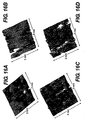
- Figures 16A, 16B, 16C, and 16D show atomic force microscopy measurements of surface roughness for some barrier layer films according to embodiments of the present invention.
- Figure 17 illustrates a water vapor transmission test that can be utilized to characterize barrier layers deposited according to embodiments of the present invention.
- Figures 18A through 18D illustrate the effects of different In/Sn breath treatment parameters on the surface roughness of the deposited barrier layer according to the present invention.
- Figures 19A and 19B illustrate the effects of the substrate on surface roughness.
- Figure 20 illustrates a barrier layer according to the present invention that further operates as a thin film gate oxide.
- Figures 21A and 21B illustrate the effect of substrate composition on the surface roughness of a deposited barrier layer according to the present invention.
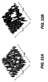
- Figures 22A and 22B illustrate that the character of the barrier layer deposition according to embodiments of the present invention effect surface roughness.
- Barrier layers according to - the present invention are deposited in a pulsed-dc, substrate biased, wide target physical vapor deposition process that is described further below with respect to some particular examples of such barrier layers.
- Some embodiments of barrier layers according to embodiments of the present invention can be characterized as highly densified, highly uniform, highly amorphous layers with particularly low defect concentrations and high surface smoothness.
- barrier layers according to embodiments of the present invention can have beneficial optical and electrical characteristics that allow such barrier layers to be self-protecting optical or electrical layers in optical or electrical devices formed with these layers.
- barrier layers according to the present invention can have excellent optical transparency characteristics.
- the index of refraction of individual barrier layers is dependent on the material of deposition and therefore stacking of multiple barrier layers according to the present invention can result in highly controllable, and self protecting, reflecting or anti-reflecting coatings for optical devices.
- barrier layers according to some embodiments of the present invention can be doped with optically active impurities to form optically active layers, which are also self-protecting.
- depositions of rare-earth ions such as Erbium or Ytterbium can result in optical amplifiers or frequency converters.
- barrier layers according to the present invention can have highly beneficial dielectric properties and can therefore be utilized as self-protecting electrical layers.
- Some barrier lavers according to embodiments of the present invention can be utilized as resistance layers.
- Other embodiments can be utilized as high-dielectric constant layers in capacitor devices. Embodiments of dielectrical barrier layers that are useful for such devices are further discussed below.
- FIGS 1A and 1B illustrate a reactor apparatus 10 for sputtering of material from a target 12 according to embodiments of the present invention.
- apparatus 10 may, for example, be adapted from an AKT-1600 PVD (400 X 500 mm substrate size) system from Applied Komatsu or an AKT-4300 (600 X 720 mm substrate size) system from Applied Komatsu, Santa Clara, CA.
- the AKT-1600 reactor for example, has three or four deposition chambers connected by a vacuum transport chamber.
- These AKT PVD reactors can be modified such that pulsed DC power is supplied to the target and RF power is supplied to the substrate during deposition of a material film.
- Apparatus 10 includes a target 12 which is electrically coupled through a filter 15 to a pulsed DC power supply 14.
- Target 12 is a wide area sputter source target, which provides material to be deposited on substrate 16.
- Substrate 16 is positioned parallel to and opposite target 12.
- Target 12 functions as a cathode when power is applied to it and is equivalently termed a cathode.
- Application of power to target 12 creates a plasma 53 below target 12.
- Magnet 20 is scanned across the top of target 12.
- Substrate 16 is capacitively coupled to an electrode 17 through an insulator 54. Electrode 17 can be coupled to an RF power supply 18.
- the polarity of the power supplied to target 12 by power supply 14 oscillates between negative and positive potentials.
- the insulating layer on the surface of target 12 is discharged and arcing is prevented.
- the pulsing frequency of pulsed DC power supply 14 can exceed a critical frequency that can depend, at least partly, on target material, cathode current and reverse time. High quality oxide films can be made using reactive pulse DC magnetron sputtering in apparatus 10.
- Pulsed DC power supply 14 can be any pulsed DC power supply, for example an AE Pinnacle plus 10K by Advanced Energy, Inc. With this example supply, up to 10 kW of pulsed DC power can be supplied at a frequency of between 0 and 350 KHz.
- the reverse voltage is 10% of the negative target voltage. Utilization of other power supplies will lead to different power characteristics, frequency characteristics and reverse voltage percentages.
- the reverse time on this embodiment of power supply 14 can be adjusted to between 0 and 5 ⁇ s.
- Filter 15 prevents the bias power from power supply 18 from coupling into pulsed DC power supply 14.
- power supply 18 is a 2 MHz RF power supply and, for example, can be a Nova-25 power supply made by ENI, Colorado Springs, Co. Therefore, filter 15 is a 2 MHz band rejection filter. In some embodiments, the band-width of the filter can be approximately 100 kHz. Filter 15, therefore, prevents the 2 MHz power from the bias to substrate 16 from damaging power supply 18.
- both RF and pulsed DC deposited films are not fully dense and most likely have columnar structures. These columnar structures are detrimental for optical applications and to formation of barrier layers due to the scattering loss and pinholes caused by the structure.
- the deposited film can be densified by energetic ion bombardment and the columnar structure can be substantially eliminated.
- target 12 can have an active size of about 675.70 X 582.48 by 4 mm in order to deposit films on substrate 16 that can have dimension about 400 X 500 mm.
- the temperature of substrate 16 can be held at between about 50C and 500C.
- the distance between target 12 and substrate 16 can be between about 3 and about 9 cm.
- Process gas (for example, but not limited to, mixtures of Ar and O 2 ) can be inserted into the chamber of apparatus 10 at a rate up to about 200 sccm while the pressure in the chamber of apparatus 10 can be held at between about 0.7 and 6 millitorr.
- Magnet 20 provides a magnetic field of strength between about 400 and about 600 Gauss directed in the plane of target 12 and is moved across target 12 at a rate of less than about 20-30 sec/scan.
- magnet 20 can be a race-track shaped magnet with dimension about 150 mm by 600 mm.
- FIG. 1C shows a dielectric barrier layer 110 deposited on a substrate 120 according to the present invention.
- Substrate 120 can be any substrate, for example plastic, glass, Si-Wafers or other material.
- Substrate 120 may further include devices or structures that can be protected by barrier layer 110, such as organic light-emitting diode (OLED) structures, semiconductor structures, or other barrier layer structures.
- Barrier layer 110 can be a metallic oxide where the metal can be Al, Si, Ti, In, Sn or other metallic oxides, nitrides, halides, or other dielectrics.
- a high index of refraction barrier layer can be formed by deposition of TiO 2 from a titanium target with example deposition parameters designated as 7KW/200W/200KHz/60Ar/9002/950s (7 KW of pulsed-dc target power, 200 W of substrate bias power, 200 KHz is the pulsing frequency of the pulsed-dc target power, 60 sccm Ar gas flow, 90 sccm O 2 gas flow, 950s total deposition time).
- Another example lower index of refraction barrier layer can be formed from a target that is 92% Al and 8% Si (i.e.
- 92-8 or 92/8 layers in a process designated as 3KW/200W/200KHZ/85Ar/9002/1025 (3KW of pulsed-dc target power, 200 W of substrate bias power, 200 KHz pulsing frequency of the pulsed-dc target power, 85 sccm Ar flow, 90 sccm O 2 flow for 1025 sec of deposition time).
- 3KW/200W/200KHZ/85Ar/9002/1025 3KW of pulsed-dc target power, 200 W of substrate bias power, 200 KHz pulsing frequency of the pulsed-dc target power, 85 sccm Ar flow, 90 sccm O 2 flow for 1025 sec of deposition time.
- Barrier layers according to the present invention can be formed from any oxide materials. For example, MgO, Ta 2 O 5 , TiO 2 , Ti 4 O 7 , Al 2 O 3 , SiO 2 , silicon-rich SiO 2 , and Y 2 O 3 . Oxide compounds of Nb, Ba, Sr, and Hf can also be utilized to form barrier layers according to the present invention. Further, barrier layers can be doped with rare-earth ions to produce optically active layers. Parameters provided herein for deposition of particular layers (e.g., the TiO 2 layers and the 92-8 layers discussed above) are exemplary only and are not intended to be limiting. Further, individual process parameters are approximations only. A wide range of individual parameters (e.g., power levels, frequencies, gas flows, and deposition times) around those stated can be used to form barrier layers according to the present invention.
- Oxide compounds of Nb, Ba, Sr, and Hf can also be utilized to form barrier layers according to the present invention.
- barrier layers can be doped
- Dielectric barrier layer 110 can be characterized as a highly dense, uniform, defect free amorphous dielectric layer that may also have high optical transparency. Such films can be deposited in a pulsed-dc, substrate biased PVD process from a metallic target in an Ar/O 2 gas flow. As is further discussed below, some embodiments of dielectric barrier layer 110 have excellent surface roughness characteristics as well. Typically, as is discussed further below and with the examples and data provided, water vapor transmission rates for dielectric films according to embodiments of the present invention are tested in a MOCON test apparatus (MOCON referes to MOCON testing service of Minneapolis, MN) to be less than 1 X 10 -2 gm/m 2 /day and are often less than 5X10 -3 gm/m 2 /day.
- MOCON referes to MOCON testing service of Minneapolis, MN
- Dielectric barrier stacks can be formed by depositing further barrier layers over barrier layer 110. Any number of stacked barrier layers can be utilized in order that the resulting structure not only function as a barrier layer, but may have other purposes in the resulting device as well. Further, a soft metallic breath treatment is applied prior to deposition of a barrier layer according to the present invention.
- a soft-metallic breath treatment refers to exposure of the substrate to a soft metallic vapor, as is further explained below.
- FIG. 2A shows an embodiment of a dielectric stack 120 that can be utilized as a barrier structure as well as providing further optical functions.
- Dielectric stack 120 includes multiple barrier layers 101, 102, 103, 104, and 105 according to embodiments of the present invention. Each of barrier layers 101, 102,103, 104, and 105 can be deposited utilizing deposition methods as described with more detail in U.S. Application Serial No. 10/101,863 . The deposition is described generally above with respect to apparatus 10.
- dielectric stack 120 can include any number of layers.
- dielectric stack 120 can include only a single barrier layer.
- the particular example of a barrier stack 120 shown in Figure 2A includes five layers, layers 101, 102, 103, 104 and 105.
- dielectric layers 101, 103 and 105 are formed of a high index material such as titania (TiO 2 ).
- Layers 102 and 104 can be formed of a low index material such as silica (SiO 2 ), possibly doped with alumina (e.g., 92% silica and 8% alumina by cation percents, the 92-8 layer).
- Barrier stack 120 can be deposited directly on a substrate 100 as shown in Figure 2A or deposited on a layer 107 as shown in Figure 2D .
- Layer 107 is a layer to be protected from atmospheric contaminants or physical damage and may include an optical or electrical device or another layer.
- Substrate 100 is a substrate on which layer 107 or dielectric stack 120 is formed. In some embodiments, substrate 100 can also provide a barrier to atmospheric contamination of layer 107. In some devices, further structures may be deposited over barrier layer structure 120.
- a dielectric barrier layer referred to as 92/8 layer refers to a barrier layer formed from continuous deposition of a dielectric barrier layer from the 92% Silica/8% Alumina target.
- a dielectric barrier layer referred to as a 92-8 layer refers to a barrier layer formed in steps from the 92% Silica/8% Alumina target.
- a 92-8 layer can be formed, for example, on plastic substrates whereas 92/8 layers can be formed on Si-wafers or glass substrates that are not so sensitive to heat.
- barrier layers are deposited by a reactively sputtered thin film layer or layers, formed by a process as previously described in the pulsed, biased deposition process, U.S. Application Serial No. 10/101,863 .
- the pulsed, biased deposition process combines optical quality vacuum films having uniquely dense morphologies free of the ' columnar defects that are typical of non-biased vacuum thin films with parts per million uniformity and control of the optical index and birefringence.
- Very high resolution ellipsometry also demonstrates that a wide range of film index can be deposited with extinction coefficients which are zero across the visible and in the near IR region, and uniform on the order of parts per million providing substantially perfect transparency.
- Selected metal oxide films deposited with the previously disclosed process are not only impervious to moisture and chemical penetration as a films, but can also provide protection to an underlying layer or device from the effect of gas or moisture ingress while serving as an optical, electrical and/or tribological layer or device, rendering substantial manufacturing and environmental margins to the respective layers and devices.
- the subject process has been demonstrated on wide area substrates of glass and metal as well as low temperature material such as plastics.
- a dielectric stack 120 is deposited on substrate 100.
- Each of barrier layers 101, 102, 103, 104, and 105 can be optical layers (i.e., layers that are optically useful).
- Substrate 100 may be any glass, plastic, metallic, or semiconductor substrate.
- the thickness of layers 101, 102,103, 104, and 105 of dielectric stack 120 can be varied to form either an anti-reflective coating or a reflective coating.
- Figure 2B shows a transparent conducting layer 106 deposited over dielectric stack 120.
- Transparent conducting layer 106 can be, for example, an indium tin-oxide layer.
- Figure 2C illustrates a substrate 100 with dielectric stacks 120 deposited on both a top surface and a bottom surface of substrate 100.
- FIG. 2C includes an embodiment of dielectric stack 120 with layers 101,102,103,104, and 105 deposited on a top surface of substrate 100 and another embodiment of dielectric stack 120, shown having layers 108, 109, 110, 111, and 112 in Figure 2C , deposited on the bottom surface of substrate 100.
- layers 108, 110, and 112 may be high index layers according to the present invention (e.g., TiO 2 layers) and layers 109 and 111 may be lower index layers such as silica/alumina layers.
- dielectric stack 120 is shown protecting a layer 107.
- Layer 107 is any layer of material that should be protected by a transparent barrier layer.
- layer 107 may be a reactive metal such as aluminum, calcium or barium
- layer 107 may be a fragile layer such as a conductive transparent oxide
- layer 107 may include an active optical or electrical device.
- the individual layers of dielectric stack 120 can provide protection both from incursion of atmospheric contaminants and protection against physical damage of layer 107.
- the layer thickness of dielectric layers (e.g., layers 101, 102, 103, 104, and 105 shown in Figure 2D ) of dielectric stack 120 are arranged to form either a transparent or reflective film at particular wavelengths.
- One skilled in the art can determine the thickness of individual films in dielectric stack 120 to form a reflective or anti-reflective film of dielectric stack 120.
- layer 107 is a metal such as aluminum, barium, or calcium
- the device shown in Figure 2D forms a highly stable mirror.
- Figure 2E shows a dielectric stack 120 protecting a layer 107 where layer 107 has been deposited on substrate 100. Further, a transparent conducting layer 106 has further been deposited over dielectric stack 120.
- Figure 2F shows a structure where a second barrier stack 120 has been deposited on the bottom surface of substrate 100.
- Figures 2A through 2F show various configurations and utilizations of a barrier stack 120 having five layers
- a barrier stack 120 according to the present invention may be formed of any number of barrier layers.
- the examples of barrier layers 101, 102, 103, 104, and 105 illustrated in Figures 2A through 2F illustrate examples of optical layers according to the present invention where those optical layers also function as self-protecting barrier layers in that they protect themselves as well as the particular surface or device on or below which they are deposited.
- one or more of barrier layers 101, 102, 103, 104, and 105 may include optically active dopant ions such as rare-earth ions in order to provide more optically active functionality.
- one or more of layers 101, 102, 103, 104, and 105 may be layers other than barrier layers according to the present invention.
- Each of the barrier layers described with respect to Figures 2A through 2F can be deposited utilizing a pulsed, biased deposition process as has been described in U.S. Application Serial No. 10/101,863 to form a highly densified layer of material with very low defect concentrations.
- FIG. 3 shows another structure 321 utilizing dielectric stacks of barrier layers according to the present invention.
- structure 321 includes a dielectric stack 315 deposited on a substrate 316.
- Substrate 316 may be formed, for example, of glass or plastic materials.
- a transparent conductive layer 314, such as for example indium tin oxide, is deposited on dielectric stack 315.
- Layer 313 can be an electroluminescence layer such as, for example, a phosphor-doped oxide or fluoride material, rare earth doped silicon rich oxide light emitting device, or an organic light emitting polymer, OLED (organic light emitting diode) or polymer stack.
- a metal layer 312, which may be aluminum and may be doped with calcium or barium, is deposited on the side near layer 313.
- a second dielectric stack 317 can be formed on the bottom of substrate 316.
- Structure 321 illustrated in Figure 3 is an example of a microcavity enhanced LED, protected from water and reactive gas which may diffuse through substrate 316 by dielectric stacks 315 and 317.
- layer 312 is a metal layer
- a microcavity is formed between layer 312 and dielectric stack 315.
- Dielectric stack 315 can out-couple light emitted from electroluminescence layer 313.
- Layer 313 emits light when it is electrically biased as a result of a voltage applied between transparent conducting layer 314 operating as an anode and conducting layer 312 operating as a cathode.
- the layers of dielectric stack 315 and dielectric stack 317 may be arranged to contain the light emitted by layer 313 between layer 317 and metallic layer 312, forming an etalon arrangement to guide light along substrate 316. Additionally, dielectric layer 317 may be arranged to transmit light produced by layer 313, thereby forming a monitor arrangement with light being emitted substantially normal to substrate 316.
- Figure 6 shows an example of another structure 633 with a microcavity enhanced LED structure 321 as described with Figure 3 covered and protected by a structure 622 such as those shown in Figures 2A through 2F .
- a structure 622 such as those shown in Figures 2A through 2F .
- layers 314, 313, and 312 have been patterned.
- a structure 622 with dielectric stacks 618 and 620 deposited on opposite sides of a substrate 619 can be formed separately.
- Dielectric stacks 618 and 619 are formed as described with dielectric stacks 120 of Figures 2A through 2F .
- Structure 622 can then be epoxied over structure 321 in order to seal and protect structure 321.
- Epoxy layer 621 for example, can be an EVA epoxy.
- Figure 7 shows another structure 700 with an example of a microcavity enhanced LED structure 321 as described with Figure 3 covered and protected by a structure 623 such as those shown in Figures 2A through 2F .
- Covering structure 623 includes substrate 619, with dielectric stack 620 deposited on substrate 619, epoxied to device 321.
- Figure 4 illustrates another example of barrier layers according to the present invention that also function as electrical layers (i.e., layers with electrical function such as providing resistance or function as the dielectric in a capacitor structure).
- the structure shown in Figure 4 illustrates an example of a bottom gate transistor structure 422 according to the present invention.
- Transistor structure 422 is formed on a substrate 416, which may be a plastic or glass material.
- a dielectric stack 415 according to the present invention is deposited on a top surface of substrate 116 and a second dielectric stack 417 according to the present invention is deposited on a bottom surface of substrate 116.
- Dielectric stacks 417 and 415 each can include layers of high index and low index dielectric materials, as discussed above.
- a semiconductor layer 423 is deposited on barrier stack 415 and patterned.
- Semiconductor layer 423 can be a semiconductor such as silicon, germanium, or may be of zinc oxide or a polymer material.
- Layers 424 and 425 form source and drain layers in contact with semiconductor layer 423.
- Layer 426 can be formed of a material with a high dielectric constant, such as any of the dielectric layers forming dielectric stacks 415 and 417, for example the high-dielectric strength TiO 2 material deposited by the processes described here.
- Layer 427 is an inter layer and layer 428 is the gate metal.
- FIG. 5 shows an example of a top gate transistor device 529.
- Transistor device 529 is formed on a substrate 516 that is protected from atmospheric contamination (for example water or gasses) and physical wear and abrasion by dielectric stacks 515 and 517.
- Dielectric stacks 515 and 517 are formed from one or more layers of optical material as discussed above with dielectric stack 120.
- Gate layer 530 is deposited on dielectric stack 515.
- Layer 530 may be a metallic layer such as aluminum or chrome.
- a gate oxide layer 531 is deposited over layer 530.
- a semiconductor layer 532 is deposited on gate oxide layer 531 over layer 530.
- Semiconducting layer 532 can be similar to layer 423 of Figure 4 .
- Layers 533 and 534 are source and drain layers, respectively, and are similar to layers 424 and 428 of device 422 of Figure 4 and may be formed from a conducting metal, conducting oxide, or a conducting polymer, for example.
- Dielectric stacks with barrier layers according to the present invention can have atomically smooth film surfaces, independent of the film thickness. Additionally, dielectric stacks with barrier layers according to the present invention can have film transparencies that are unmeasurably different from zero. These dielectric stacks represent a new capability for biased barrier film defect levels and barrier protection. Few products requiring dielectric barrier protection from water and oxygen, such as OLED displays, can tolerate a defect every square centimeter. Some embodiments of barrier layers as 2.5 nanometers and as thick as 15 microns have been deposited that exhibit an average surface roughness of about 0.2 nm, indicating a damage free process. Such layers exhibit an optical quality surface for all film thicknesses deposited, representative of the high amorphous film uniformity attainable with these processes that produce embodiments of the barrier layer according to the present invention.
- Dielectric barrier layers according to the present invention have been shown to protect ultra thin reactive metal films of aluminum from steam heat oxidation from 125 to 250 °C at pressures of 3.5 ATM of pure steam for hundreds of hours with no visible defect on 100mm silicon wafers. Consequently, it is clear that both titanium oxide and alumina/silicate barrier layers, as described herein, can provide long term protection of reactive films which are pin hole free up to the area of one or both wafers.
- a soft metal, such as indium or indium-tin, breath treatment is performed before deposition of one or more barrier layers such as those discussed above. It is likely that the soft metal breath treatment can be utilized to release stress between the dielectric barrier layer and the substrate. Further, the soft metal breath treatment can act to nucleate for further growth of pin-hole free or defect-free barrier layer films on the substrate.
- Figures 12A and 12B show a single barrier layer structure 1200 with deposited on a substrate 1201 with and without a soft-metal breath treatment according to the present invention.
- a barrier layer 1203 such as is described above is deposited directly on substrate 1201.
- Substrate 1201 can be any suitable substrate material, including glass, plastic, or Si Wafers, for example.
- Substrate 1201 can, for example, include an OLED structure or other optically active structure which requires high optical throughput or an electrical structure that may utilize the barrier layers as electrical layers.
- Barrier layer 1203 can be any one or more barrier layers as is described above. As illustrated in Figure 12A , barrier layer 1203 can develop stress-related surface roughness during deposition and use.
- Figure 12B illustrates the results of depositing barrier layer 1203 following a soft-metal breath treatment according to the present invention. As is shown in Figure 12B , the stress is apparently relieved resulting in a barrier layer with much better surface smoothness.
- the soft-metal breath treatment of the present invention includes an exposure of the substrate for a short time to a soft metal vapor followed by a heat treatment.
- An indium-tin breath treatment for example, involves exposure of the substrate to indium-tin from an indium-tin target in a pulsed-dc process and a subsequent heat treatment. Direct exposure to indium-tin-oxide vapor does not yield the particular beneficial results illustrated below.
- an In/Sn breath treatment can relieve stress in the deposited barrier layer, improving surface smoothness and MOCON WVTR performance.
- barrier layer structure 1200 an embodiment of a soft-metal breath treatment was performed on a plastic substrate 1201.
- a breath treatment of Indium/Tin for example, can be performed from an Indium Tin (90%/10%) Target.
- the process for performing the indium/tin breath treatment can be designated as 750W/0W/200 KHz/20Ar/002/10sec.
- the pulsed-dc, biased, wide target PVD process is operated with a 90% Indium/10% Tin target, an Ar flow of 20 sccms running at a constant power of 750 W in a pulsed PVD system 10 ( Figure 1A ) (Pulsing Frequency 200 KHz, Reverse time 2.2 ⁇ sec) for 10 secs in the AKT 1600 PVD system using the Pinnacle Plus PDC power supply.
- the breath treatment continued and substrate 1201 was transferred into a load lock of an AKT 4300 Tool and the Tool was pumped to a base pressure of less than about 1X10 -5 Torr.
- the substrate was then transferred to a Heat Chamber at 130 °C at 1X10 -8 Torr where it is thermally treated at 130 °C for about 25 min.
- Substrate 1201 (with the indium/tin breath treatment described above) was then moved to a second chamber where barrier layer 1203 is deposited.
- Barrier layer 1203 can be formed, as indicated above, from a 92-8 Alumino-Silicate (92% Si/8% Al) target with the deposition performed at room temperature.
- the process parameters for the deposition of the embodiment of 92-8 barrier layer 1203 can be 3KW/200W/200KHz/85Ar/9002/x. Therefore, the process is performed with about 3 KW PDC power, about 200 KHz Pulsing Frequency, and about 2.2 microseconds reverse time. Bias power can be held at about 200 W. A Gas flow of about 85 sccms of Ar and about 90 sccms of O 2 was utilized. In deposition of this particular embodiment, the deposition process was power cycled where the on cycle was about 180 secs long and the off cycle was about 600 secs long for 9 cycles. The thickness of the resulting barrier layer 1203 was then about 1600 A.
- barrier structure 1200 with substrate 1201 being three plastic sheets of size 6 inch by 6 inch (Dupont Teijin PEN films 200 ⁇ m thick, referred to as a PEN substrate).
- any barrier layer e.g., the 92-8 or TiO 2 layers discussed above
- any barrier layer can be deposited following a soft-metal breath treatment.
- examples of processes for embodiments of barrier layers according to the present invention are presented here but wide ranges of process parameters can result in barrier layers according to the present invention.
- Barrier layer structure 1200 on substrate 1201 can then be tested using a variety of techniques, some of which are described below.
- the stress in layer 1203 can be measured using a Flexus Stress Measurement technique.
- Surface roughness can be measured utilizing an atomic force microscope (AFM), and water vapor transmission rates (WVTR) can be measured in a high pressure, high humidity pressure cooker device.
- AFM atomic force microscope
- WVTR water vapor transmission rates
- Figure 13 illustrates a Flexus Scanning Assembly 1300 that can be utilized to test barrier layer structure 1200.
- a light beam for laser 1310 is directed onto the upper surface of barrier layer 1203 by a mirror 1312.
- the reflected light beam from barrier layer 1203 is detected by detector 1314.
- Detector 1314 measures the deflection of the light beam from the beam reflected by mirror 1312.
- the optical section 1316 which can include laser 1310, mirror 1312, and detector 1314, can be scanned across substrate 1201 and the angle of deflection ⁇ , which is related to the radius of curvature of substrate 1201 as shown in relation 1318.
- the thin film stress in barrier 1203 can be calculated utilizing the changes in substrate deformation measured by Flexus apparatus 1300 as optical portion 1316 is scanned. As is shown in relationship 1318, the angle of the reflected beam can be monitored during the scan and the inverse of the radius of curvature R of substrate 1201 can be calculated from the derivative of the angle as a function of position in the scan.
- Flexus apparatus 1300 can utilize a dual wavelength technology to increase the range of film types that the tool is capable of measuring. Each Flexus apparatus 1300, then, can have more than one laser 1310 available for scanning the wafer since different film types will reflect different wavelengths of light. Further, the reflected laser intensity provides a good indication of the quality of the measurement. In general, low light intensity at detector 1314 indicates a poor measurement condition.
- stress can be determined using Stoney's equation.
- stress in layer 1203 can be determined by measurements of the radius of curvature before deposition of layer 1203 and the radius of curvature after deposition of layer 1203.
- both measurements of the radius of curvature should be performed on the same tool to minimize systematic error in the measured radius.
- each wafer should have a baseline radius measurement.
- a positive radius indicates tensile stress and a negative radius indicates compressive stress.
- Wafer bow can be calculated, as shown in Figure 14 , by measuring the maximum point of deflection from the chord connecting the end-points of a scan of Flux apparatus 1300.
- barrier films 1203 where barrier film 1203 is a 92-8 film as discussed above with and without a nucleation layer 1202 formed by a soft-metal breath treatment is tabulated in Table 2.
- sample 1 was a 1.5 K ⁇ 92-8 film of actual thickness 1760 ⁇ deposited on a Si-Wafer substrate. The resulting stress at about room temperature was -446.2 MPa.
- Sample 2 was a 1.5 K ⁇ 92-8 film of actual thickness 1670 ⁇ over an Al-breath deposition resulted in a stress of about -460.2 MPa.
- Atomic-force microscopy can be utilized to measure surface roughness of a film.
- AFM Atomic-force microscopy
- a miniature probe is physically scanned over the surface of a film such that the probe is in contact, and follows the surface, of the film.
- the probe has a small tip and therefore is capable of accurately monitoring the surface roughness for features on the order of a few nanometers.
- Figure 16A shows the surface roughness of a PEN substrate (Dupont Teijin PEN films 200 ⁇ m thickness), before deposition of a barrier layer according to the present invention.
- a PEN substrate typically has a surface roughness of average 2.2 nm, root-mean-square average RMS of 3.6 nm, and a typical maximum roughness of about 41.0 nm.
- deposition of a 1.5 K ⁇ 92-8 after an indium-tin breath treatment on a PEN substrate results in an average surface roughness of 1.0 nm with RMS roughness of 1.7 nm and maximum roughness of 23.6 nm.
- an indium-tin-oxide (ITO) breath treatment was performed before the 1.5 K A 92-8 barrier layer film deposition resulted in an average roughness of 2.1 nm with RMS roughness of 3.4 nm and maximum roughness of 55.4 nm.
- the deposition shown in Figure 16C is performed with a 125 ⁇ m PEN substrate rather than a 200 ⁇ m PEN substrate. Therefore, a direct ITO treatment does not perform as well as treatment with an indium-tin breath.
- FIG 17 illustrates a water vapor transmission (WVTR) testing apparatus 1700 that can be utilized to characterize barrier layer films according to embodiments of the present invention.
- a sample 1701 can be mounted into apparatus 1700 in such a way that the surface of substrate 1201 ( Figure 12 ) is isolated from the surface of barrier layer 1203 ( Figure 12 ).
- a moisture-free gas is input to port 1702, contacts one surface of sample 1701, and is directed to sensor 1703 where the water vapor coming from sample 1701 is monitored.
- a humid gas is directed to the opposite side of sample 1701 through port 1705.
- An RH probe 1704 can be utilized to monitor the water content of the gas input to port 1705. Sensor 1703, then, monitors the water vapor that is transmitted through sample 1701.
- Such tests are performed by Mocon Testing Service, 7500 Boone Avenue North, Minneapolis, MN 55428.
- Mocon testing is pereformed in accordance with ASTM F1249 standards.
- instruments utilized for WVTR testing by Mocon can detect transmission in the range 0.00006gm/100in 2 /day to 4grn/100in 2 /day.
- the Mocon 3/31 instrument for example, has a lower detection limit of about 0.0003gm/100in 2 /day.
- a barrier layer deposition formed with an Al-breath treatment followed by a 1.5 K A 92-8 barrier layer deposition on a 200 ⁇ m PEN substrate resulted in a Mocon test WVTR of 0.0631 gm/100in 2 /day.
- a barrier layer deposition formed with an In-breath treatment followed by a 1.5 K A 92-8 on 200 ⁇ m PEN substrate resulting in no measurable WVTR in the Mocon 3/31 instrument (i.e., the transmission rate was less than 0.0003 gm/100in 2 /day).
- Figures 16A through D illustrates the role that a soft-metal breath treatment (in particular an indium breath treatment) can play in determining the surface roughness of a deposited barrier layer according to the present invention.
- the surface roughness of a barrier layer can also affect the WVTR characteristics of a barrier layer. Smoother barrier layer result in better WVTR performance.
- Figure 16A shows a bare 200 ⁇ m PEN substrate with no barrier.
- Figure 16B shows a 200 ⁇ m PEN substrate with a 1500 ⁇ thickness 92-8 barrier layer deposited after a In/Sn breath treatment according to the present invention.
- Figure 16C illustrates a 200 ⁇ m PEN substrate with a 1500 ⁇ 92-8 barrier layer deposited after treatment with ITO breath.
- Figure 16D is a 200 ⁇ m PEN substrate with a 1500 ⁇ 92-8 barrier layer directly deposited on the substrate. As can be seen, the structure of Figure 16B shows the best surface smoothness characteristics.
- Table 3 illustrates several examples of barrier layers, with surface smoothness characteristics and MOCON WVTR testing results.
- the samples described in rows 1-4 are 92-8 layers (as described above) of thickness about 2000 ⁇ deposited on one or both sides of a 700 ⁇ m thick polycarbonate (LEXAN produced by General Electric, corp.).
- LEXAN produced by General Electric, corp.
- the data shows that the double-side coated barrier layer structure (rows 1 and 2) perform about an order of magnitude better in MOCON WVTR test than does the one sided structures (rows 3 and 4).
- Rows 5 through 8 illustrate various deposition on a PEN substrate (with rows 5-6 describing deposition on a 200 ⁇ m PEN substrate and rows 7 and 8 describing depositions on a 125 ⁇ m PEN substrate).
- the In breath treatment parameters refer to In/Sn breath treatments as discussed above.
- the AFM parameters are shown in Figures 16B through 16D as described earlier.
- the best surface smoothness and the best WVTR characteristics are shown in row 6, with In breath treatment followed by deposition of a 92-8 layer.
- the data in row 9 indicates an In breath treatment (In/Sn) with higher power on a thinner (125 ⁇ m) PEN substrate.
- the thermal stress behavior on a 125 ⁇ m PEN substrate is worse than that for a 200 ⁇ m PEN substrate.
- Further indication of this effect is shown in the data of rows 30 through 33 along with Figures 19A and 19B .
- the data in rows 30 and 31 include a indium/tin breath treatment (at 750W) on a 200 ⁇ m PEN substrate followed by about 1.5 k ⁇ 92-8 layer deposition, which yields a very smooth surface (e.g., about 1.1nm average) as shown in Figure 19A and an undetectable MOCON WVTR characteristic on the MOCON 3/31 test equipment.
- the 92-8 depositions illustrated in rows 30 through 33 were concurrently performed in a single operation.
- the data in rows 12 and 13 of Table 3 indicate an In-breath treatment plus 1.5 k ⁇ TiO 2 deposition on a 125 ⁇ m PEN substrate.
- Data in rows 10 and 11 indicate an In/Sn-breath treatment plus 1.5 k ⁇ 92-8 deposition on a 125 ⁇ m PEN substrate.
- the WVTR characteristics of 92-8 layers is more than an order of magnitude better than the WVTR characteristics of TiO 2 layers.
- Representative smoothness for rows 12 and 13 are presented in Figure 22A and representative smoothness for rows 10 and 11 are presented in Figure 22B .
- the average smoothness for 92-8 layers is approximately an order of magnitude better than the average smoothness for TiO 2 .
- the data in rows 14 and 15 of Table 3 illustrate an In/Sn breath treatment on a 125 ⁇ m LEXAN substrate followed by a 92-8 layer deposition.
- the data in rows 14 and 15 can be compared with the data in rows 32 and 33, which are In/Sn breath treatment on a 125 ⁇ m PEN substrate followed by a 1.5 K ⁇ 92-8 layer deposition.
- the smoothness is comparable between the LEXAN and PEN substrate, although as can be seen in a comparison of Figures 21A and 21B , the morphology is different, i.e. barrier layers according to the present invention deposited on the LEXAN substrate show more granularity than barrier layers deposited on the PEN substrate.
- the data in rows 16 through 18 of Table 3 illustrate different process parameters for an In/Sn breath treatment followed by 1.5 K ⁇ 92-8 deposition on a 200 ⁇ m PEN substrate.
- the data in row 16 illustrates a setting where the current is set rather than power.
- the data in row 16 is taken with a current of 6.15 amps.
- the In/Sn breath treatment is performed at 1.5 kW of operating power.
- the In/Sn breath treatment is performed at 750 W of operating power.
- the MOCON WVTR characteristic of the resulting barrier layer is below detectability on the MOCON 3/31 instrument.
- the data in rows 19-29 of Table 3 illustrate different In/Sn breath treatments and their effects on the surface smoothness of the resulting barrier layers and on the MOCON WVTR characteristics.
- the data in rows 19-22 are all examples of where the In/Sn breath treatment is replaced with a evaporated In layer followed by a 130 C preheat treatment.
- the surface roughness characteristics are illustrated in Figure 18A and shows an average roughness of about 1.1 nm. However, the morphology is very granular as is shown in Figure 18A , with presumably a lot of porosity, resulting in MOCON WVTR test on the order of .8 gm/m 2 /day.
- the data shown in row 23 of Table 3 illustrates the case where no In/Sn breath treatment is utilized and the 200 ⁇ m PEN substrate is preheated before deposition of a 1.5 k ⁇ 92-8 deposition, which as shown in Figure 18C has a surface rouglmess of about 5.2 nm average and a MOCON WVTR of about 0.8 gm/m 2 /day, or the same as is shown with the indium evaporation vapor data shown in rows 19-22. Therefore, the same characteristics result whether an indium evaporation vapor treatment is applied or not.
- Rows 24-29 of Table 3 illustrate data where an In/Sn breath treatment was performed at 280 °C rather than at room temperature.
- the surface roughness, as is illustrated in Figure 18B was about 1.1 nm average.
- the MOCON WVTR data was about 3 X 10 -2 gm/m 2 /day. This value is much higher than that shown in the similar depositions of rows 30 and 31, which were below 5 X 10 -3 gm/m 2 /day detectability limits of the MOCON 3/31 instrument.
- the data in rows 34 and 35 illustrates deposition of a 1.5 k ⁇ 35-65 layer (i.e., a deposition with a target having 35% Si and 65 % Al) following a In/Sn deposition on a 200 ⁇ m PEN substrate.
- the MOCON WVTR are 1.4 X 10 -1 gm/m 2 /day, which shows the possible necessity of a biased process for producing barrier layers according to the present invention.
- Figure 20 illustrates a barrier layer 2002 that can also operate as a thin film gate oxide deposited on a substrate 2001.
- a thin film gate oxide 2002 can be deposited as a barrier layer according to the present invention. Such a layer as the benefit of protecting moisture and oxygen sensitive transistor layer compounds of germanium, tin oxide, zinc oxide, or pentacene, for example, while functioning as the thin oxide electrical layer.
- Substrate 2001 can include any electrical device that can be formed on, for example, a silicon wafer, plastic sheet, glass plate, or other material.
- Barrier layer 2002 can be a thin layer, for example from 25 to 500 ⁇ .
- Titanium oxide is well known as the preferred material for biological implantation due to the lack of immunological response to titanium oxide.
- a thin film of TiO 2 which is an immunologically indifferent barrier layer, can simultaneously protect a device such as a voltage or charge sensor or an optical device such as a waveguide while performing the role of coupling the device capacitively or optically due to its' high dielectric constant or its' high optical index.
- An array of capacitors can be coupled by the high capacitive density due to the proximity of the sensor provided by a very thin high-k dielectric such as TiO 2 .
- a micron or sub micron array can be used to monitor the electrical activity, amplitude, and direction of very low electrical signals such as those that accompany the propagation of electrical signals in single axion of single neural ganglia. Conversely, it can also be used to electrically couple stimulus to adjacent cells or tissue.
- High resolution, high-capacitance coupling to the optic nerve, the auditory nerve, or neural tissue on the order of 5 to 50 femto-farads/ ⁇ m 2 is made uniquely feasible by such a capacitive barrier film without immunological reaction.
Description
- The present invention is related to dielectric barrier films and, in particular, dielectric barrier films formed from high-density optical material layers for utilization in optical, electrical, tribological, and bio-implantable devices.
- Dielectric barrier layers are becoming increasingly important as protective layers for organic light emitting diodes (OLEDs) and other optical or optoelectronic devices. Typically, dielectric barrier layers are deposited thin films with the appropriate electrical, physical, and optical properties to protect and enhance the operation of other devices. Dielectric barrier layers can be utilized in optical, electrical, or tribological devices. For example, touch screen displays require optically transparent protective layers to protect against transmission of atmospheric contaminants as well as to protect against physical wear.
- Many thin film deposition technologies that may be utilized to form such dielectric layers include some form of ion densification or substrate bias densification. The densification process eliminates the columnar thin film structure that is typical of vacuum deposited chemical vapor (CVD) or physical vapor deposition (PVD) thin films. It is well known that such densification can be achieved by a secondary ion source arranged to "bombard" the film during deposition. See, e.g., W. Essinger "Ion sources for ion beam assisted thin film deposition," Rev. Sci. Instruments (63) 11-5217 (1992). See, also, Hrvoje Zorc, et al. Proceedings of the Society of Vacuum Coaters, 41st Annual Technical Conference Proceedings, 243-247, 1998, which discusses the effects of moisture exposure on wavelength shift for electron beam evaporated films (e-beams). In particular, Zorc et al. demonstrated a factor of 15 or so improvement in wavelength shift for electron beam evaporated films (e-beam) as compared to e-beam films deposited with a directed ion beam source after exposure to 30% humidity at 25 °C.
- D. E. Morton, et al. demonstrated wide-band dielectric pass filters comprised of alternating layers of SiO2 and TiO2 deposited using a "cold cathode ion source" to produce oxygen ions for the purpose of providing "moisture stable stacks of dense optical films of silicon dioxide as the low index material and either titanium dioxide, tantalum pentoxide or niobium pentoxide." D. E. Morton, et al. Proceedings of the Society of Vacuum Coaters, 41st annual Technical Conference, April 18-23, 1998. The results described by Morton, et al., indicated that room temperature resistance to humidity up to 100% humidity was attained, as measured by the optical performance of single dielectric layers deposited on substrates mounted on a rotating platen. Optical extinction coefficients for the six samples tested in Morton, et al., varied from 0.1 to 1.6 ppt, indicating the presence of significant concentrations of defects or absorption centers in the dielectric layers. Additionally, no film thickness or film thickness uniformity data was reported by Morton, et al., for ion beam energies between 134 and 632 Volts and ion beam current up to 5 amps. Morton, et al., therefore fail to describe a film that would operate as a good barrier layer for optical devices.
- Self biased physical vapor deposition, such as ion coating or activated reactive deposition, are well-known means of providing hard wear resistant coatings. However, these coatings are either deposited at several hundred Volts of bias voltage and form penetrating surface treatments with the ion flux penetrating the surface to react with the substrate material, or they are ion assisted for the purpose of decreasing the columnar structure of the film. A "filtered cathodic vacuum arc" (FCVA-reference - http://www.nanofilm-systems.com /eng/fcva_technology.htm) has been used to form a dense film from an ion flux. In this case, ions are created and separated from the neutral vapor flux by a magnetic vector so that only species having a positive charge impinge the substrate. The bias voltage can be preset so that average translational energy ranges from about 50 to several hundred Volts are available. Lower ion energies are not reported due to the problem of extracting and directing a lower energy ion flux with a useful space charge density. Although quite rough due to re-sputtering at the high ion energies, hard protective layers of alumina, and other materials such as tetrahedral carbon, can be deposited with this process on cutting tools and twist drills with commercial levels of utility. Due to the limitation of the coating species to the ion flux, coating rates are low. The best or hardest carbon films are often deposited with the lowest rate of deposition, e.g., 0.3 nanometers per second on substrates up to 12" in diameter.
- Transmission of a ZnO film deposited by FCVA at 600 nm wavelength is increased from about 50% at room temperature to above 80% for single films by increasing the temperature of deposition to above 230 °C, with the best transmission at 600 nm of about 90% at a deposition temperature of 430 °C and a substrate bias voltage not greater than about 50 Volts. This high temperature processing indicates the use of a thermal anneal process for repair of ion-induced damage to the films. For FCVA deposition with a 200 Volt bias the transmission is much reduced. FCVA films deposited in this fashion have been shown to be polycrystalline. The defect structures exhibited in the FCVA layer are too large for formation of effective optical barrier layers. Additionally, ion sputtering of crystalline films is dependent on the crystal orientation, leading to higher surface roughness. Defect structures formed in a protective layer can degrade the optical quality of the layer and also provide paths for diffusion of atmospheric contaminations through the layer, compromising the protective properties of the layer.
- Ion biased films have shown significant progress toward the goal of providing a satisfactory barrier for protection of electronic and optical films, such as, for example, photovoltaic, semiconducting and electroluminescent films. Particularly organic light emitting diodes, which utilize calcium or other very reactive metal doped electrodes and other hydroscopic or reactive materials, can be protected by such films. However, the most biased process to date, the filtered Cathodic Vacuum Arc Coating Technology or FCVAC process, is reported to produce films with a particle density greater than about 1 defect per square centimeter. It may be that the high resputtering rate at the high voltages used in this process cause surface roughening. Certainly, the presence of a particle represents a defect through which diffusion of water vapor or oxygen can proceed. Also, the roughness of the surface formed by the FCVAC process impacts the stress and morphology and also the transparency and the uniformity of the index of refraction. The resputtered film may flake from the process chamber shields or be drawn to the film surface by the large electrostatic field present in an ion beam process. In any case, the particle defect density for particles greater than the film thickness also determines pin hole density or other defects caused by discontinuous deposition of the film because line of sight films can not coat over a particle that is larger than the thickness of the film, let alone a particle many times greater in size than the thickness of the film.
- In the case of ion-bias or self-bias energies exceeding several electron volts, the translational energy of the ion participating in the bias process can exceed the chemical binding energy of the film. The impacting ion, then, can either forward scatter atoms of the existing film or back sputter atoms of the existing film. Likewise, the participating ion can be adsorbed into the growing film or it can also scatter or absorb from the film surface. Sputtering of the existing film and scattering from the existing film are both favored at incoming angles of about 45° from the horizontal. In most ion coating processes, the ion beam is directed at a normal incidence to the surface to be coated. However, as noted, at ion energies exceeding the chemical threshold, and particularly at energies exceeding 20 Volts or so, damage to the film or the substrate resulting from the ion energy in excess of the chemical binding energy is significant, and results in surface roughness, increased optical absorption characteristics, and creation of defects.
- In the case of the FCVA process, roughness is an increasing function of the film thickness, increasing from about 0.2 nanometers roughness for a 50 nanometer film to about 3 nanometers for a 400 nanometer Cu film indicating substantial roughening of the polycrystalline copper surface due to differential sputtering by the self biased incoming copper ions. Such a film will scatter light, particularly at the interface between two layers of different refractive index. To date, barrier or dielectric properties of FCVA produced films have not been found.
- Charging of the deposited film is also a particular problem with ion beam deposited dielectrics. To date, no low temperature dielectric and also no ion beam dielectric is known that has ever been shown to provide the electrical quality required for a transistor gate layer, for example. The ion beams embed charged ions in the film, leading to large negative flat band voltages and fields that can not be passivated at temperatures below about 450 °C. The surface charge of the dielectric layer results in slow accumulation of capacitance, preventing the sharp onset of conduction in a transistor application. Consequently, no as-deposited low temperature dielectric, biased or unbiased, has been proposed for low temperature transistor applications or is known at this time.
J-Y KIM et al in JOURNAL OF VACUUM SCIENCE AND TECHNOLOGY A. VACUUM, SURFACES AND FILMS, vol. 19, no. 2, March 2001 (2001-03), pages 429-434, describe the deposition of amorphous titanium oxide films by pulsed direct current magnetron sputtering. - Therefore, there is a need for high quality, dense dielectric layers for utilization as barrier layers in optical, electrical, tribological, and biomedical applications.
- According to an aspect of the present invention, there is provided a method of forming a barrier layer comprising: providing a substrate; performing a soft-metal breath treatment on the substrate by exposing the substrate for a short time to a soft metal vapour followed by a heat treatment; providing an RF bias to the substrate; applying a pulsed-DC power to a wide-area target opposite the substrate; and depositing a highly densified, amorphous, dielectric material over the substrate.
- In accordance with the present invention, one or more dielectric layers formed from layers of metal-oxide materials deposited by a pulsed, biased, wide area physical vapor deposition process are presented. A dielectric barrier layer according to the present invention can be formed from at least one highly densified metal oxide layer. Dielectric barriers according to the present invention can be highly densified, highly uniform, ultra smooth amorphous layers with ultra low concentrations of defects, providing for superior performance as protective layers against physical wear and atmospheric contamination of underlying structures as well as overlying structures that may be deposited to form an electrical, optical, or medical device. Barrier layers according to the present invention can also be self-protecting optical layers, electrical layers, or tribological layers that can be utilized actively in optical or electrical devices.
- Therefore, barrier layers according to the present invention includes a densified amorphous dielectric layer deposited on a substrate by pulsed-DC, substrate biased physical vapor deposition, wherein the densified amorphous dielectric layer is a barrier layer. Further the deposition is performed with a wide area target. A method of forming a barrier layer according to the present inventions includes providing a substrate and depositing a highly densified, amorphous, dielectric material over the substrate in a pulsed-dc, biased, wide target physical vapor deposition process. Further, the process includes performing a soft-metal breath treatment on the substrate.
- Dielectric barrier stacks can include any number of individual layers including one or more barrier layers according to the present invention. In some embodiments, the individual barrier layers can be optical layers. Typically, alternating layers of low and high index of refractory metal oxide materials can be arranged to form anti-reflective or reflective coatings in optical devices, for example. As such, dielectric barriers according to the present invention provide a protective function as well as being a functional part of an optical device. In some embodiments of the invention, for example, dielectric barriers according to the present invention can be utilized in cavity enhanced LED applications, or in formation and protection of transistor structures. Additionally, the beneficial dielectric properties of some embodiments of barrier layers according to the present invention can be utilized as electrical layers to form resistors or capacitive dielectrics.
- A soft metal (e.g., indium) breath treatment is utilized before deposition of a barrier layer. Such a breath treatment is shown to significantly improve surface roughness and enhance WVTR characteristics for embodiments of barrier layers according to the present invention.
- These and other embodiments of the invention are further discussed and explained below with reference to the following Figures. It is to be understood that both the foregoing general description and the following detailed description are exemplary and explanatory only and are not restrictive of the invention, as claimed. Further, specific explanations or theories regarding the deposition or performance of barrier layers or soft-metal breath treatments according to the present invention are presented for explanation only and are not to be considered limiting with respect to the scope of the present disclosure or the claims.
-
Figures 1A and 1B illustrate a deposition apparatus for depositing barrier layer films according to the present invention. -
Figure 1C illustrates a barrier layer deposited on a substrate according to embodiments of the present invention. -
Figures 2A, 2B, 2C, 2D ,2E and 2F illustrate examples of devices with dielectric stacks of barrier layers according to embodiments of the present invention. -
Figure 3 shows a microcavity enhanced LED structure utilizing dielectric stacks of barrier layers according to embodiments of the present invention. -
Figure 4 shows a bottom gate transistor device with a dielectric stack of barrier layers according to embodiments of the present invention. -
Figure 5 shows a top gate transistor device with a dielectric stack of barrier layers according to embodiments of the present invention. -
Figure 6 shows an example of a microcavity enhanced LED structure similar to that shown inFigure 3 further protected by a dielectric stack of barrier layers according to embodiments of the present invention. -
Figure 7 shows another example of a microcavity enhanced LED structure similar to that shown inFigure 3 further protected by a dielectric stack of barrier layers according to embodiments of the present invention. -
Figures 12A and 12B illustrate a single barrier layer structure deposited with and without a soft-metal breath treatment. -
Figure 13 shows a Flexus Stress Measurement apparatus that can be utilized to test barrier layers. -
Figure 14 illustrates a measurement of the wafer bow using the Flexus Stress Measurement apparatus illustrated inFigure 13 . -
Figure 15 illustrates the stress in various deposited barrier layers according to embodiments of the present invention as a function of temperature through a single temperature cycle after deposition. -
Figures 16A, 16B, 16C, and 16D show atomic force microscopy measurements of surface roughness for some barrier layer films according to embodiments of the present invention. -
Figure 17 illustrates a water vapor transmission test that can be utilized to characterize barrier layers deposited according to embodiments of the present invention. -
Figures 18A through 18D illustrate the effects of different In/Sn breath treatment parameters on the surface roughness of the deposited barrier layer according to the present invention. -
Figures 19A and 19B illustrate the effects of the substrate on surface roughness. -
Figure 20 illustrates a barrier layer according to the present invention that further operates as a thin film gate oxide. -
Figures 21A and 21B illustrate the effect of substrate composition on the surface roughness of a deposited barrier layer according to the present invention. -
Figures 22A and 22B illustrate that the character of the barrier layer deposition according to embodiments of the present invention effect surface roughness. - In the figures, elements having the same designation have the same or similar functions.
- Barrier layers according to - the present invention are deposited in a pulsed-dc, substrate biased, wide target physical vapor deposition process that is described further below with respect to some particular examples of such barrier layers. Some embodiments of barrier layers according to embodiments of the present invention can be characterized as highly densified, highly uniform, highly amorphous layers with particularly low defect concentrations and high surface smoothness. Further, barrier layers according to embodiments of the present invention can have beneficial optical and electrical characteristics that allow such barrier layers to be self-protecting optical or electrical layers in optical or electrical devices formed with these layers.
- For example, some embodiments of barrier layers according to the present invention can have excellent optical transparency characteristics. Further, the index of refraction of individual barrier layers is dependent on the material of deposition and therefore stacking of multiple barrier layers according to the present invention can result in highly controllable, and self protecting, reflecting or anti-reflecting coatings for optical devices. Additionally, barrier layers according to some embodiments of the present invention can be doped with optically active impurities to form optically active layers, which are also self-protecting. For example, depositions of rare-earth ions such as Erbium or Ytterbium can result in optical amplifiers or frequency converters.
- Additionally, embodiments of barrier layers according to the present invention can have highly beneficial dielectric properties and can therefore be utilized as self-protecting electrical layers. Some barrier lavers according to embodiments of the present invention, for example, can be utilized as resistance layers. Other embodiments can be utilized as high-dielectric constant layers in capacitor devices. Embodiments of dielectrical barrier layers that are useful for such devices are further discussed below.
- RF sputtering of oxide films is discussed
US 2002 033 330 A09/903,050 US 2003 175142A , corresponding toU.S. Application serial no. 10/101,341, filed on March 16, 2002
Methods of depositing oxides in a pulsed-dc, substrate biased, wide-target physical vapor deposition (PVD) process are further discussed inUS 2003 173207A corresponding toU.S. Application serial no. 10/101863, filed on March 16, 2002 -
Figures 1A and 1B illustrate areactor apparatus 10 for sputtering of material from atarget 12 according to embodiments of the present invention. In some embodiments,apparatus 10 may, for example, be adapted from an AKT-1600 PVD (400 X 500 mm substrate size) system from Applied Komatsu or an AKT-4300 (600 X 720 mm substrate size) system from Applied Komatsu, Santa Clara, CA. The AKT-1600 reactor, for example, has three or four deposition chambers connected by a vacuum transport chamber. These AKT PVD reactors can be modified such that pulsed DC power is supplied to the target and RF power is supplied to the substrate during deposition of a material film. -
Apparatus 10 includes atarget 12 which is electrically coupled through afilter 15 to a pulsedDC power supply 14.Target 12 is a wide area sputter source target, which provides material to be deposited onsubstrate 16.Substrate 16 is positioned parallel to andopposite target 12.Target 12 functions as a cathode when power is applied to it and is equivalently termed a cathode. Application of power to target 12 creates aplasma 53 belowtarget 12.Magnet 20 is scanned across the top oftarget 12.Substrate 16 is capacitively coupled to anelectrode 17 through aninsulator 54.Electrode 17 can be coupled to anRF power supply 18. - For pulsed reactive dc magnetron sputtering, as performed by
apparatus 10, the polarity of the power supplied to target 12 bypower supply 14 oscillates between negative and positive potentials. During the period of positive potential, the insulating layer on the surface oftarget 12 is discharged and arcing is prevented. To obtain arc free deposition, the pulsing frequency of pulsedDC power supply 14 can exceed a critical frequency that can depend, at least partly, on target material, cathode current and reverse time. High quality oxide films can be made using reactive pulse DC magnetron sputtering inapparatus 10. - Pulsed
DC power supply 14 can be any pulsed DC power supply, for example an AE Pinnacle plus 10K by Advanced Energy, Inc. With this example supply, up to 10 kW of pulsed DC power can be supplied at a frequency of between 0 and 350 KHz. The reverse voltage is 10% of the negative target voltage. Utilization of other power supplies will lead to different power characteristics, frequency characteristics and reverse voltage percentages. The reverse time on this embodiment ofpower supply 14 can be adjusted to between 0 and 5 µs. -
Filter 15 prevents the bias power frompower supply 18 from coupling into pulsedDC power supply 14. In some embodiments,power supply 18 is a 2 MHz RF power supply and, for example, can be a Nova-25 power supply made by ENI, Colorado Springs, Co. Therefore, filter 15 is a 2 MHz band rejection filter. In some embodiments, the band-width of the filter can be approximately 100 kHz.Filter 15, therefore, prevents the 2 MHz power from the bias tosubstrate 16 fromdamaging power supply 18. - However, both RF and pulsed DC deposited films are not fully dense and most likely have columnar structures. These columnar structures are detrimental for optical applications and to formation of barrier layers due to the scattering loss and pinholes caused by the structure. By applying a RF bias on
wafer 16 during deposition, the deposited film can be densified by energetic ion bombardment and the columnar structure can be substantially eliminated. - In the production of some embodiments of a barrier layer according to the present invention using, for example, the AKT-1600 based system, target 12 can have an active size of about 675.70 X 582.48 by 4 mm in order to deposit films on
substrate 16 that can have dimension about 400 X 500 mm. The temperature ofsubstrate 16 can be held at between about 50C and 500C. The distance betweentarget 12 andsubstrate 16 can be between about 3 and about 9 cm. Process gas (for example, but not limited to, mixtures of Ar and O2) can be inserted into the chamber ofapparatus 10 at a rate up to about 200 sccm while the pressure in the chamber ofapparatus 10 can be held at between about 0.7 and 6 millitorr.Magnet 20 provides a magnetic field of strength between about 400 and about 600 Gauss directed in the plane oftarget 12 and is moved acrosstarget 12 at a rate of less than about 20-30 sec/scan. In some embodiments utilizing the AKT 1600 reactor,magnet 20 can be a race-track shaped magnet with dimension about 150 mm by 600 mm. -
Figure 1C shows adielectric barrier layer 110 deposited on asubstrate 120 according to the present invention.Substrate 120 can be any substrate, for example plastic, glass, Si-Wafers or other material.Substrate 120 may further include devices or structures that can be protected bybarrier layer 110, such as organic light-emitting diode (OLED) structures, semiconductor structures, or other barrier layer structures.Barrier layer 110 can be a metallic oxide where the metal can be Al, Si, Ti, In, Sn or other metallic oxides, nitrides, halides, or other dielectrics. For example, a high index of refraction barrier layer can be formed by deposition of TiO2 from a titanium target with example deposition parameters designated as 7KW/200W/200KHz/60Ar/9002/950s (7 KW of pulsed-dc target power, 200 W of substrate bias power, 200 KHz is the pulsing frequency of the pulsed-dc target power, 60 sccm Ar gas flow, 90 sccm O2 gas flow, 950s total deposition time). Another example lower index of refraction barrier layer can be formed from a target that is 92% Al and 8% Si (i.e. 92-8 or 92/8 layers) in a process designated as 3KW/200W/200KHZ/85Ar/9002/1025 (3KW of pulsed-dc target power, 200 W of substrate bias power, 200 KHz pulsing frequency of the pulsed-dc target power, 85 sccm Ar flow, 90 sccm O2 flow for 1025 sec of deposition time). As is further discussed below, a wide range of process parameters can be utilized to deposit barrier layers according to the present invention. - Barrier layers according to the present invention can be formed from any oxide materials. For example, MgO, Ta2O5, TiO2, Ti4O7, Al2O3, SiO2, silicon-rich SiO2, and Y2O3. Oxide compounds of Nb, Ba, Sr, and Hf can also be utilized to form barrier layers according to the present invention. Further, barrier layers can be doped with rare-earth ions to produce optically active layers. Parameters provided herein for deposition of particular layers (e.g., the TiO2 layers and the 92-8 layers discussed above) are exemplary only and are not intended to be limiting. Further, individual process parameters are approximations only. A wide range of individual parameters (e.g., power levels, frequencies, gas flows, and deposition times) around those stated can be used to form barrier layers according to the present invention.
-
Dielectric barrier layer 110 can be characterized as a highly dense, uniform, defect free amorphous dielectric layer that may also have high optical transparency. Such films can be deposited in a pulsed-dc, substrate biased PVD process from a metallic target in an Ar/O2 gas flow. As is further discussed below, some embodiments ofdielectric barrier layer 110 have excellent surface roughness characteristics as well. Typically, as is discussed further below and with the examples and data provided, water vapor transmission rates for dielectric films according to embodiments of the present invention are tested in a MOCON test apparatus (MOCON referes to MOCON testing service of Minneapolis, MN) to be less than 1 X 10⁻² gm/m2/day and are often less than 5X10⁻³ gm/m2/day. - Dielectric barrier stacks can be formed by depositing further barrier layers over
barrier layer 110. Any number of stacked barrier layers can be utilized in order that the resulting structure not only function as a barrier layer, but may have other purposes in the resulting device as well. Further, a soft metallic breath treatment is applied prior to deposition of a barrier layer according to the present invention. A soft-metallic breath treatment refers to exposure of the substrate to a soft metallic vapor, as is further explained below. -
Figure 2A shows an embodiment of adielectric stack 120 that can be utilized as a barrier structure as well as providing further optical functions.Dielectric stack 120 includes multiple barrier layers 101, 102, 103, 104, and 105 according to embodiments of the present invention. Each of barrier layers 101, 102,103, 104, and 105 can be deposited utilizing deposition methods as described with more detail inU.S. Application Serial No. 10/101,863 . The deposition is described generally above with respect toapparatus 10. In general,dielectric stack 120 can include any number of layers. In particular,dielectric stack 120 can include only a single barrier layer. The particular example of abarrier stack 120 shown inFigure 2A includes five layers, layers 101, 102, 103, 104 and 105. In the example ofdielectric stack 120 shown inFigure 2A ,dielectric layers Layers Barrier stack 120 can be deposited directly on asubstrate 100 as shown inFigure 2A or deposited on alayer 107 as shown inFigure 2D .Layer 107 is a layer to be protected from atmospheric contaminants or physical damage and may include an optical or electrical device or another layer.Substrate 100 is a substrate on whichlayer 107 ordielectric stack 120 is formed. In some embodiments,substrate 100 can also provide a barrier to atmospheric contamination oflayer 107. In some devices, further structures may be deposited overbarrier layer structure 120. - In general, in this disclosure a dielectric barrier layer referred to as 92/8 layer refers to a barrier layer formed from continuous deposition of a dielectric barrier layer from the 92% Silica/8% Alumina target. A dielectric barrier layer referred to as a 92-8 layer refers to a barrier layer formed in steps from the 92% Silica/8% Alumina target. A 92-8 layer can be formed, for example, on plastic substrates whereas 92/8 layers can be formed on Si-wafers or glass substrates that are not so sensitive to heat.
- In some barrier stacks according to the present invention, barrier layers are deposited by a reactively sputtered thin film layer or layers, formed by a process as previously described in the pulsed, biased deposition process,
U.S. Application Serial No. 10/101,863 . The pulsed, biased deposition process combines optical quality vacuum films having uniquely dense morphologies free of the ' columnar defects that are typical of non-biased vacuum thin films with parts per million uniformity and control of the optical index and birefringence. Very high resolution ellipsometry also demonstrates that a wide range of film index can be deposited with extinction coefficients which are zero across the visible and in the near IR region, and uniform on the order of parts per million providing substantially perfect transparency. As a result of the high level of densification and the low defect concentration, it is demonstrated that these very transparent films also provide superior diffusion barrier protection for moisture ingress as measured by steam permeation. Lastly, the same films demonstrate much higher dielectric breakdown under high voltage stress, also a result of the low levels of defects. - Selected metal oxide films deposited with the previously disclosed process, from tens of nanometers to more than 15 microns, are not only impervious to moisture and chemical penetration as a films, but can also provide protection to an underlying layer or device from the effect of gas or moisture ingress while serving as an optical, electrical and/or tribological layer or device, rendering substantial manufacturing and environmental margins to the respective layers and devices. The subject process has been demonstrated on wide area substrates of glass and metal as well as low temperature material such as plastics.
- Returning to
Figure 2A , adielectric stack 120 is deposited onsubstrate 100. Each of barrier layers 101, 102, 103, 104, and 105 can be optical layers (i.e., layers that are optically useful).Substrate 100 may be any glass, plastic, metallic, or semiconductor substrate. The thickness oflayers 101, 102,103, 104, and 105 ofdielectric stack 120 can be varied to form either an anti-reflective coating or a reflective coating.Figure 2B shows atransparent conducting layer 106 deposited overdielectric stack 120.Transparent conducting layer 106 can be, for example, an indium tin-oxide layer.Figure 2C illustrates asubstrate 100 withdielectric stacks 120 deposited on both a top surface and a bottom surface ofsubstrate 100. The particular example shown inFigure 2C includes an embodiment ofdielectric stack 120 with layers 101,102,103,104, and 105 deposited on a top surface ofsubstrate 100 and another embodiment ofdielectric stack 120, shown havinglayers Figure 2C , deposited on the bottom surface ofsubstrate 100. Again, layers 108, 110, and 112 may be high index layers according to the present invention (e.g., TiO2 layers) and layers 109 and 111 may be lower index layers such as silica/alumina layers. - In
Figure 2D dielectric stack 120 is shown protecting alayer 107.Layer 107 is any layer of material that should be protected by a transparent barrier layer. For example,layer 107 may be a reactive metal such as aluminum, calcium or barium,layer 107 may be a fragile layer such as a conductive transparent oxide, orlayer 107 may include an active optical or electrical device. As discussed above, the individual layers ofdielectric stack 120 can provide protection both from incursion of atmospheric contaminants and protection against physical damage oflayer 107. In some embodiments, the layer thickness of dielectric layers (e.g., layers 101, 102, 103, 104, and 105 shown inFigure 2D ) ofdielectric stack 120 are arranged to form either a transparent or reflective film at particular wavelengths. One skilled in the art can determine the thickness of individual films indielectric stack 120 to form a reflective or anti-reflective film ofdielectric stack 120. In some embodiments, wherelayer 107 is a metal such as aluminum, barium, or calcium, the device shown inFigure 2D forms a highly stable mirror.Figure 2E shows adielectric stack 120 protecting alayer 107 wherelayer 107 has been deposited onsubstrate 100. Further, atransparent conducting layer 106 has further been deposited overdielectric stack 120.Figure 2F shows a structure where asecond barrier stack 120 has been deposited on the bottom surface ofsubstrate 100. - Although
Figures 2A through 2F show various configurations and utilizations of abarrier stack 120 having five layers, in general, abarrier stack 120 according to the present invention may be formed of any number of barrier layers. Further, the examples of barrier layers 101, 102, 103, 104, and 105 illustrated inFigures 2A through 2F illustrate examples of optical layers according to the present invention where those optical layers also function as self-protecting barrier layers in that they protect themselves as well as the particular surface or device on or below which they are deposited. Additionally, one or more of barrier layers 101, 102, 103, 104, and 105 may include optically active dopant ions such as rare-earth ions in order to provide more optically active functionality. Further, in accordance with the present invention, one or more oflayers Figures 2A through 2F can be deposited utilizing a pulsed, biased deposition process as has been described inU.S. Application Serial No. 10/101,863 to form a highly densified layer of material with very low defect concentrations. -
Figure 3 shows anotherstructure 321 utilizing dielectric stacks of barrier layers according to the present invention. As shown inFigure 3 ,structure 321 includes adielectric stack 315 deposited on asubstrate 316.Substrate 316 may be formed, for example, of glass or plastic materials. A transparentconductive layer 314, such as for example indium tin oxide, is deposited ondielectric stack 315.Layer 313 can be an electroluminescence layer such as, for example, a phosphor-doped oxide or fluoride material, rare earth doped silicon rich oxide light emitting device, or an organic light emitting polymer, OLED (organic light emitting diode) or polymer stack. Ametal layer 312, which may be aluminum and may be doped with calcium or barium, is deposited on the side nearlayer 313. A seconddielectric stack 317 can be formed on the bottom ofsubstrate 316. -
Structure 321 illustrated inFigure 3 is an example of a microcavity enhanced LED, protected from water and reactive gas which may diffuse throughsubstrate 316 bydielectric stacks layer 312 is a metal layer, a microcavity is formed betweenlayer 312 anddielectric stack 315.Dielectric stack 315 can out-couple light emitted fromelectroluminescence layer 313.Layer 313 emits light when it is electrically biased as a result of a voltage applied betweentransparent conducting layer 314 operating as an anode and conductinglayer 312 operating as a cathode. The layers ofdielectric stack 315 anddielectric stack 317 may be arranged to contain the light emitted bylayer 313 betweenlayer 317 andmetallic layer 312, forming an etalon arrangement to guide light alongsubstrate 316. Additionally,dielectric layer 317 may be arranged to transmit light produced bylayer 313, thereby forming a monitor arrangement with light being emitted substantially normal tosubstrate 316. -
Figure 6 shows an example of another structure 633 with a microcavity enhancedLED structure 321 as described withFigure 3 covered and protected by astructure 622 such as those shown inFigures 2A through 2F . Instructure 321, as shown inFigure 6 , layers 314, 313, and 312 have been patterned. Astructure 622 withdielectric stacks substrate 619 can be formed separately.Dielectric stacks dielectric stacks 120 ofFigures 2A through 2F .Structure 622 can then be epoxied overstructure 321 in order to seal and protectstructure 321.Epoxy layer 621, for example, can be an EVA epoxy. -
Figure 7 shows another structure 700 with an example of a microcavity enhancedLED structure 321 as described withFigure 3 covered and protected by a structure 623 such as those shown inFigures 2A through 2F . Covering structure 623 includessubstrate 619, withdielectric stack 620 deposited onsubstrate 619, epoxied todevice 321. -
Figure 4 illustrates another example of barrier layers according to the present invention that also function as electrical layers (i.e., layers with electrical function such as providing resistance or function as the dielectric in a capacitor structure). The structure shown inFigure 4 illustrates an example of a bottomgate transistor structure 422 according to the present invention.Transistor structure 422 is formed on asubstrate 416, which may be a plastic or glass material. In the embodiment illustrated inFigure 4 , adielectric stack 415 according to the present invention is deposited on a top surface of substrate 116 and a seconddielectric stack 417 according to the present invention is deposited on a bottom surface of substrate 116.Dielectric stacks semiconductor layer 423 is deposited onbarrier stack 415 and patterned.Semiconductor layer 423 can be a semiconductor such as silicon, germanium, or may be of zinc oxide or a polymer material.Layers semiconductor layer 423.Layer 426 can be formed of a material with a high dielectric constant, such as any of the dielectric layers formingdielectric stacks Layer 427 is an inter layer andlayer 428 is the gate metal. -
Figure 5 shows an example of a topgate transistor device 529.Transistor device 529 is formed on asubstrate 516 that is protected from atmospheric contamination (for example water or gasses) and physical wear and abrasion bydielectric stacks Dielectric stacks dielectric stack 120.Gate layer 530 is deposited ondielectric stack 515.Layer 530 may be a metallic layer such as aluminum or chrome. Agate oxide layer 531 is deposited overlayer 530. Asemiconductor layer 532 is deposited ongate oxide layer 531 overlayer 530.Semiconducting layer 532 can be similar tolayer 423 ofFigure 4 .Layers layers device 422 ofFigure 4 and may be formed from a conducting metal, conducting oxide, or a conducting polymer, for example. - Dielectric stacks with barrier layers according to the present invention can have atomically smooth film surfaces, independent of the film thickness. Additionally, dielectric stacks with barrier layers according to the present invention can have film transparencies that are unmeasurably different from zero. These dielectric stacks represent a new capability for biased barrier film defect levels and barrier protection. Few products requiring dielectric barrier protection from water and oxygen, such as OLED displays, can tolerate a defect every square centimeter. Some embodiments of barrier layers as 2.5 nanometers and as thick as 15 microns have been deposited that exhibit an average surface roughness of about 0.2 nm, indicating a damage free process. Such layers exhibit an optical quality surface for all film thicknesses deposited, representative of the high amorphous film uniformity attainable with these processes that produce embodiments of the barrier layer according to the present invention.
- Dielectric barrier layers according to the present invention have been shown to protect ultra thin reactive metal films of aluminum from steam heat oxidation from 125 to 250 °C at pressures of 3.5 ATM of pure steam for hundreds of hours with no visible defect on 100mm silicon wafers. Consequently, it is clear that both titanium oxide and alumina/silicate barrier layers, as described herein, can provide long term protection of reactive films which are pin hole free up to the area of one or both wafers. One pin hole in the protective dielectric barrier on a 100 mm wafer, with an area of approximately 75 square centimeters, would translate into a pin hole density of about 0.0133 per square centimeter. As shown in Figures 8 and 9, there were two wafers, one with aluminosilicate and one with titania barrier dielectric coatings, that were failure free. The total area between the two wafers was 150 square centimeters. If there were 1 defect on these two wafers the defect density would be 0.00666 per square centimeter. However, since the wafers were free of defects, the actual defect density could not be measured from the results of only two wafers. As indicated, then, the actual defect density was less than 0.0133 per square centimeter and likely less than 0.007 per square centimeter.
- A soft metal, such as indium or indium-tin, breath treatment is performed before deposition of one or more barrier layers such as those discussed above. It is likely that the soft metal breath treatment can be utilized to release stress between the dielectric barrier layer and the substrate. Further, the soft metal breath treatment can act to nucleate for further growth of pin-hole free or defect-free barrier layer films on the substrate.
-
Figures 12A and 12B show a singlebarrier layer structure 1200 with deposited on asubstrate 1201 with and without a soft-metal breath treatment according to the present invention. InFigure 12A , abarrier layer 1203 such as is described above is deposited directly onsubstrate 1201.Substrate 1201 can be any suitable substrate material, including glass, plastic, or Si Wafers, for example.Substrate 1201 can, for example, include an OLED structure or other optically active structure which requires high optical throughput or an electrical structure that may utilize the barrier layers as electrical layers.Barrier layer 1203 can be any one or more barrier layers as is described above. As illustrated inFigure 12A ,barrier layer 1203 can develop stress-related surface roughness during deposition and use. -
Figure 12B illustrates the results of depositingbarrier layer 1203 following a soft-metal breath treatment according to the present invention. As is shown inFigure 12B , the stress is apparently relieved resulting in a barrier layer with much better surface smoothness. - The soft-metal breath treatment of the present invention includes an exposure of the substrate for a short time to a soft metal vapor followed by a heat treatment. An indium-tin breath treatment, for example, involves exposure of the substrate to indium-tin from an indium-tin target in a pulsed-dc process and a subsequent heat treatment. Direct exposure to indium-tin-oxide vapor does not yield the particular beneficial results illustrated below. Without being bound by a particular theory that may be presented in this disclosure, an In/Sn breath treatment can relieve stress in the deposited barrier layer, improving surface smoothness and MOCON WVTR performance.
- In a particular example of formation of
barrier layer structure 1200, an embodiment of a soft-metal breath treatment was performed on aplastic substrate 1201. A breath treatment of Indium/Tin, for example, can be performed from an Indium Tin (90%/10%) Target. The process for performing the indium/tin breath treatment can be designated as 750W/0W/200 KHz/20Ar/002/10sec. In other words, the pulsed-dc, biased, wide target PVD process is operated with a 90% Indium/10% Tin target, an Ar flow of 20 sccms running at a constant power of 750 W in a pulsed PVD system 10 (Figure 1A ) (Pulsing Frequency 200 KHz, Reverse time 2.2 µsec) for 10 secs in the AKT 1600 PVD system using the Pinnacle Plus PDC power supply. Then, the breath treatment continued andsubstrate 1201 was transferred into a load lock of an AKT 4300 Tool and the Tool was pumped to a base pressure of less than about 1X10⁻⁵ Torr. The substrate was then transferred to a Heat Chamber at 130 °C at 1X10⁻⁸ Torr where it is thermally treated at 130 °C for about 25 min. - Substrate 1201 (with the indium/tin breath treatment described above) was then moved to a second chamber where
barrier layer 1203 is deposited.Barrier layer 1203 can be formed, as indicated above, from a 92-8 Alumino-Silicate (92% Si/8% Al) target with the deposition performed at room temperature. - The process parameters for the deposition of the embodiment of 92-8
barrier layer 1203 can be 3KW/200W/200KHz/85Ar/9002/x. Therefore, the process is performed with about 3 KW PDC power, about 200 KHz Pulsing Frequency, and about 2.2 microseconds reverse time. Bias power can be held at about 200 W. A Gas flow of about 85 sccms of Ar and about 90 sccms of O2 was utilized. In deposition of this particular embodiment, the deposition process was power cycled where the on cycle was about 180 secs long and the off cycle was about 600 secs long for 9 cycles. The thickness of the resultingbarrier layer 1203 was then about 1600 A. In a particular test, the process described above was utilized for deposition of abarrier structure 1200 withsubstrate 1201 being three plastic sheets of size 6 inch by 6 inch (DupontTeijin PEN films 200 µm thick, referred to as a PEN substrate). In general, any barrier layer (e.g., the 92-8 or TiO2 layers discussed above) can be deposited following a soft-metal breath treatment. As discussed before, examples of processes for embodiments of barrier layers according to the present invention are presented here but wide ranges of process parameters can result in barrier layers according to the present invention. -
Barrier layer structure 1200 onsubstrate 1201 can then be tested using a variety of techniques, some of which are described below. In particular, the stress inlayer 1203 can be measured using a Flexus Stress Measurement technique. Surface roughness can be measured utilizing an atomic force microscope (AFM), and water vapor transmission rates (WVTR) can be measured in a high pressure, high humidity pressure cooker device. -
Figure 13 illustrates aFlexus Scanning Assembly 1300 that can be utilized to testbarrier layer structure 1200. InFlexus Scanning Assembly 1300, a light beam forlaser 1310 is directed onto the upper surface ofbarrier layer 1203 by amirror 1312. The reflected light beam frombarrier layer 1203 is detected bydetector 1314.Detector 1314 measures the deflection of the light beam from the beam reflected bymirror 1312. Theoptical section 1316, which can includelaser 1310,mirror 1312, anddetector 1314, can be scanned acrosssubstrate 1201 and the angle of deflection θ, which is related to the radius of curvature ofsubstrate 1201 as shown inrelation 1318. - The thin film stress in
barrier 1203 can be calculated utilizing the changes in substrate deformation measured byFlexus apparatus 1300 asoptical portion 1316 is scanned. As is shown inrelationship 1318, the angle of the reflected beam can be monitored during the scan and the inverse of the radius of curvature R ofsubstrate 1201 can be calculated from the derivative of the angle as a function of position in the scan. - In some cases,
Flexus apparatus 1300 can utilize a dual wavelength technology to increase the range of film types that the tool is capable of measuring. EachFlexus apparatus 1300, then, can have more than onelaser 1310 available for scanning the wafer since different film types will reflect different wavelengths of light. Further, the reflected laser intensity provides a good indication of the quality of the measurement. In general, low light intensity atdetector 1314 indicates a poor measurement condition. - In
Flexus apparatus 1300, stress can be determined using Stoney's equation. In particular, stress inlayer 1203 can be determined by measurements of the radius of curvature before deposition oflayer 1203 and the radius of curvature after deposition oflayer 1203. In particular, according to Stoney's equation, the stress can be given by
where Es/(1-vs) is the biaxial modulus ofsubstrate 1201, σ is the stress ofsubstrate 1201, ts is the substrate thickness, tf is the film thickness, Rs is the pre-deposition radius of curvature, and Rf is the post deposition radius of curvature. To obtain the best results, both measurements of the radius of curvature should be performed on the same tool to minimize systematic error in the measured radius. In addition, because the shape of a wafer is unique and because stress is calculated based on the change in deformation of the substrate, each wafer should have a baseline radius measurement. A positive radius indicates tensile stress and a negative radius indicates compressive stress. Wafer bow can be calculated, as shown inFigure 14 , by measuring the maximum point of deflection from the chord connecting the end-points of a scan ofFlux apparatus 1300. - Measurements of stress performed on several embodiments of
barrier films 1203 wherebarrier film 1203 is a 92-8 film as discussed above with and without a nucleation layer 1202 formed by a soft-metal breath treatment is tabulated in Table 2. As shown in Table 2,sample 1 was a 1.5 KÅ 92-8 film of actual thickness 1760 Å deposited on a Si-Wafer substrate. The resulting stress at about room temperature was -446.2 MPa. Sample 2 was a 1.5 KÅ 92-8 film of actual thickness 1670 Å over an Al-breath deposition resulted in a stress of about -460.2 MPa. Insample 3, a 1.5 KÅ 92-8 film of thickness 1860 Å was deposited subsequent to a In-breath deposition and resulted in a stress of -330.2 MPa, nearly 100 MPa lower than either of the other two depositions depicted.
As can be seen fromFigure 15 , 92-8 films deposited over an In-breath treatment exhibited much less stress than did either a 92-8 film deposited over an Al-breath treatment or a 92-8 film deposited over the substrate without a soft-metal breath treatment. - Atomic-force microscopy (AFM) can be utilized to measure surface roughness of a film. In AFM, a miniature probe is physically scanned over the surface of a film such that the probe is in contact, and follows the surface, of the film. The probe has a small tip and therefore is capable of accurately monitoring the surface roughness for features on the order of a few nanometers.
-
Figure 16A shows the surface roughness of a PEN substrate (DupontTeijin PEN films 200 µm thickness), before deposition of a barrier layer according to the present invention. As is shown inFigure 16A , a PEN substrate typically has a surface roughness of average 2.2 nm, root-mean-square average RMS of 3.6 nm, and a typical maximum roughness of about 41.0 nm. As shown inFigure 16B , deposition of a 1.5 KÅ 92-8 after an indium-tin breath treatment on a PEN substrate results in an average surface roughness of 1.0 nm with RMS roughness of 1.7 nm and maximum roughness of 23.6 nm. As is shown inFigure 16C , an indium-tin-oxide (ITO) breath treatment was performed before the 1.5 K A 92-8 barrier layer film deposition resulted in an average roughness of 2.1 nm with RMS roughness of 3.4 nm and maximum roughness of 55.4 nm. The deposition shown inFigure 16C is performed with a 125 µm PEN substrate rather than a 200 µm PEN substrate. Therefore, a direct ITO treatment does not perform as well as treatment with an indium-tin breath. As shown inFigure 16D , deposition of a barrier layer of 1.5 K A directly on a 125 µm PEN substrate resulted in a barrier layer with average surface roughness of about 5.2 nm with RMS roughness of 8.5 nm and maximum roughness of 76.0 nm. Therefore, although the ITO breath treatment was better than no soft-metal treatment at all with respect to surface roughness, an indium-tin breath treatment resulted in the best surface roughness yielding an average surface roughness of about 1.0 nm. -
Figure 17 illustrates a water vapor transmission (WVTR)testing apparatus 1700 that can be utilized to characterize barrier layer films according to embodiments of the present invention. Asample 1701 can be mounted intoapparatus 1700 in such a way that the surface of substrate 1201 (Figure 12 ) is isolated from the surface of barrier layer 1203 (Figure 12 ). A moisture-free gas is input to port 1702, contacts one surface ofsample 1701, and is directed tosensor 1703 where the water vapor coming fromsample 1701 is monitored. A humid gas is directed to the opposite side ofsample 1701 throughport 1705. AnRH probe 1704 can be utilized to monitor the water content of the gas input toport 1705.Sensor 1703, then, monitors the water vapor that is transmitted throughsample 1701. - Such tests are performed by Mocon Testing Service, 7500 Boone Avenue North, Minneapolis, MN 55428. In addition, the Mocon testing is pereformed in accordance with ASTM F1249 standards. Typically, instruments utilized for WVTR testing by Mocon can detect transmission in the range 0.00006gm/100in2/day to 4grn/100in2/day. The
Mocon 3/31 instrument, for example, has a lower detection limit of about 0.0003gm/100in2/day. - A barrier layer deposition formed with an Al-breath treatment followed by a 1.5 K A 92-8 barrier layer deposition on a 200 µm PEN substrate resulted in a Mocon test WVTR of 0.0631 gm/100in2/day. A barrier layer deposition formed with an In-breath treatment followed by a 1.5 K A 92-8 on 200 µm PEN substrate resulting in no measurable WVTR in the
Mocon 3/31 instrument (i.e., the transmission rate was less than 0.0003 gm/100in2/day). - As was further discussed above,
Figures 16A through D illustrates the role that a soft-metal breath treatment (in particular an indium breath treatment) can play in determining the surface roughness of a deposited barrier layer according to the present invention. The surface roughness of a barrier layer can also affect the WVTR characteristics of a barrier layer. Smoother barrier layer result in better WVTR performance. As such,Figure 16A shows a bare 200 µm PEN substrate with no barrier.Figure 16B shows a 200 µm PEN substrate with a 1500 Å thickness 92-8 barrier layer deposited after a In/Sn breath treatment according to the present invention.Figure 16C illustrates a 200 µm PEN substrate with a 1500 Å 92-8 barrier layer deposited after treatment with ITO breath.Figure 16D is a 200 µm PEN substrate with a 1500 Å 92-8 barrier layer directly deposited on the substrate. As can be seen, the structure ofFigure 16B shows the best surface smoothness characteristics. - Table 3 illustrates several examples of barrier layers, with surface smoothness characteristics and MOCON WVTR testing results. In Table 3, the samples described in rows 1-4 are 92-8 layers (as described above) of thickness about 2000 Å deposited on one or both sides of a 700 µm thick polycarbonate (LEXAN produced by General Electric, corp.). The data shows that the double-side coated barrier layer structure (
rows 1 and 2) perform about an order of magnitude better in MOCON WVTR test than does the one sided structures (rows 3 and 4). - Rows 5 through 8 illustrate various deposition on a PEN substrate (with rows 5-6 describing deposition on a 200 µm PEN substrate and rows 7 and 8 describing depositions on a 125 µm PEN substrate). The In breath treatment parameters refer to In/Sn breath treatments as discussed above. The AFM parameters are shown in
Figures 16B through 16D as described earlier. As discussed before, the best surface smoothness and the best WVTR characteristics are shown in row 6, with In breath treatment followed by deposition of a 92-8 layer. The data in row 9 indicates an In breath treatment (In/Sn) with higher power on a thinner (125 µm) PEN substrate. Presumably, the thermal stress behavior on a 125 µm PEN substrate is worse than that for a 200 µm PEN substrate. Further indication of this effect is shown in the data of rows 30 through 33 along withFigures 19A and 19B . The data in rows 30 and 31 include a indium/tin breath treatment (at 750W) on a 200 µm PEN substrate followed by about 1.5 kÅ 92-8 layer deposition, which yields a very smooth surface (e.g., about 1.1nm average) as shown inFigure 19A and an undetectable MOCON WVTR characteristic on theMOCON 3/31 test equipment. The data in rows 32 and 33, with In/Sn breath treatment followed by 1.5 kÅ 92-8 layer deposition on 125 µm PEN substrate, shows worse smoothness (about 2.0 nm average roughness) and a WVTR test in the MOCON apparatus of about 1.7 X 10⁻² gm/m2/day. The 92-8 depositions illustrated in rows 30 through 33 were concurrently performed in a single operation. - The data in
rows 12 and 13 of Table 3 indicate an In-breath treatment plus 1.5 kÅ TiO2 deposition on a 125 µm PEN substrate. Data inrows 10 and 11 indicate an In/Sn-breath treatment plus 1.5 kÅ 92-8 deposition on a 125 µm PEN substrate. As can be seen in Table 3, the WVTR characteristics of 92-8 layers is more than an order of magnitude better than the WVTR characteristics of TiO2 layers. Representative smoothness forrows 12 and 13 are presented inFigure 22A and representative smoothness forrows 10 and 11 are presented inFigure 22B . As is shown in Table 3, the average smoothness for 92-8 layers is approximately an order of magnitude better than the average smoothness for TiO2. - The data in
rows rows Figures 21A and 21B , the morphology is different, i.e. barrier layers according to the present invention deposited on the LEXAN substrate show more granularity than barrier layers deposited on the PEN substrate. - The data in
rows 16 through 18 of Table 3 illustrate different process parameters for an In/Sn breath treatment followed by 1.5 KÅ 92-8 deposition on a 200 µm PEN substrate. The data inrow 16 illustrates a setting where the current is set rather than power. The data inrow 16 is taken with a current of 6.15 amps. In the barrier layer illustrated inrow 17, the In/Sn breath treatment is performed at 1.5 kW of operating power. In the barrier layer illustrated inrow 18, the In/Sn breath treatment is performed at 750 W of operating power. In each case, the MOCON WVTR characteristic of the resulting barrier layer is below detectability on theMOCON 3/31 instrument. - The data in rows 19-29 of Table 3 illustrate different In/Sn breath treatments and their effects on the surface smoothness of the resulting barrier layers and on the MOCON WVTR characteristics. The data in rows 19-22 are all examples of where the In/Sn breath treatment is replaced with a evaporated In layer followed by a 130 C preheat treatment. The surface roughness characteristics are illustrated in
Figure 18A and shows an average roughness of about 1.1 nm. However, the morphology is very granular as is shown inFigure 18A , with presumably a lot of porosity, resulting in MOCON WVTR test on the order of .8 gm/m2/day. The data shown in row 23 of Table 3 illustrates the case where no In/Sn breath treatment is utilized and the 200 µm PEN substrate is preheated before deposition of a 1.5 kÅ 92-8 deposition, which as shown inFigure 18C has a surface rouglmess of about 5.2 nm average and a MOCON WVTR of about 0.8 gm/m2/day, or the same as is shown with the indium evaporation vapor data shown in rows 19-22. Therefore, the same characteristics result whether an indium evaporation vapor treatment is applied or not. - Rows 24-29 of Table 3 illustrate data where an In/Sn breath treatment was performed at 280 °C rather than at room temperature. The surface roughness, as is illustrated in
Figure 18B , was about 1.1 nm average. However, the MOCON WVTR data was about 3 X 10⁻² gm/m2/day. This value is much higher than that shown in the similar depositions of rows 30 and 31, which were below 5 X 10⁻³ gm/m2/day detectability limits of theMOCON 3/31 instrument. - The data in rows 34 and 35 illustrates deposition of a 1.5 kÅ 35-65 layer (i.e., a deposition with a target having 35% Si and 65 % Al) following a In/Sn deposition on a 200 µm PEN substrate. As is illustrated, the MOCON WVTR are 1.4 X 10⁻¹ gm/m2/day, which shows the possible necessity of a biased process for producing barrier layers according to the present invention.
-
Figure 20 illustrates abarrier layer 2002 that can also operate as a thin film gate oxide deposited on asubstrate 2001. A thinfilm gate oxide 2002 can be deposited as a barrier layer according to the present invention. Such a layer as the benefit of protecting moisture and oxygen sensitive transistor layer compounds of germanium, tin oxide, zinc oxide, or pentacene, for example, while functioning as the thin oxide electrical layer.Substrate 2001 can include any electrical device that can be formed on, for example, a silicon wafer, plastic sheet, glass plate, or other material.Barrier layer 2002 can be a thin layer, for example from 25 to 500 Å. - Titanium oxide is well known as the preferred material for biological implantation due to the lack of immunological response to titanium oxide. In addition, it is preferred that a thin film of TiO2, which is an immunologically indifferent barrier layer, can simultaneously protect a device such as a voltage or charge sensor or an optical device such as a waveguide while performing the role of coupling the device capacitively or optically due to its' high dielectric constant or its' high optical index.
- An array of capacitors can be coupled by the high capacitive density due to the proximity of the sensor provided by a very thin high-k dielectric such as TiO2. In practice, a micron or sub micron array can be used to monitor the electrical activity, amplitude, and direction of very low electrical signals such as those that accompany the propagation of electrical signals in single axion of single neural ganglia. Conversely, it can also be used to electrically couple stimulus to adjacent cells or tissue. High resolution, high-capacitance coupling to the optic nerve, the auditory nerve, or neural tissue on the order of 5 to 50 femto-farads/µm2 is made uniquely feasible by such a capacitive barrier film without immunological reaction.
- Other embodiments of the invention will be apparent to those skilled in the art from consideration of the specification and practice of the invention disclosed herein. This disclosure is not limited by any theories or hypothesis of operation that are utilized to explain any results presented. It is intended that the specification and examples be considered as exemplary only, with a true scope being indicated by the following claims. As such, this application is limited only by the following claims.
TABLE 2 Id Comment Temp °C Radius (m) Stress Mpa Film Thickness (Å) Bow (µm) Sample 1 pre-deposition 21 -4.76E+03 N/A N/A 1.58 1.5 KÅ 92-8 film deposition/ no In-breath treatment 27 -145.978 -446.2 1760 11.74 Sample 2 pre-deposition 29 -4.10E+03 N/A N/A 1.38 Al breath deposition then 1.5 KÅ 92-8 film treatment 36 -169.482 -460.2 1670 10.18 Sample 3 pre-deposition 25 -230.249 N/A N/A 4.36 In breath treatment then 1.5 KÅ 92-8 film deposition 25 -67.169 -330.2 1860 10.25 TABLE 3 Sample ID Sample Description Substrate Material Thickness µm MOCON WVTR (g/100inch2/day ) MOCON WVTR (g/m2/day) AFM Results 1 (Film (coated on both sides) - A) 2 KÅ 92-8 on Polycarbonate, deposited on both sides-A LEXAN 700 7.2000E-04 1.1160E-02 2 (Film (coated on both sides) - B) 2 KÅ 92-8 on Polycarbonate, deposited on both sides-B LEXAN 700 5.8000E-04 8.9900E-03 3 (Film (coated on one side) -A) 2 KÅ 92-8 on Polycarbonate - A LEXAN 700 8.3000E-03 1.2865E-01 4 (Film (coated on one side) -B) 2 KÅ 928 on Polycarbonate - B LEXAN 700 1.7200E-02 2.6660E-01 5 (Al+1.5K928) A1-breath (500W 10sec+ 130c heat treatment) + 1.5 KÅ 92-8 on PEN PEN Q65 200 6.3100E-02 9.7805E-01 In Breath (750W 5sec+ 130c heat treatment) + 1.5 KÅ 92-8 on PEN Ra=1.3nm RMS=1.5nm Rmax=9.8nm 6 (InB + 1.5K928) PEN Q65 200 3.0000E-04 4.6500E-03 See Figure 16B 7 (102-MOCON ID: 1619-003) NO In Breath + 130c Preheat + 1.5 KÅ 92-8 on PEN Ra=5.2nm RMS=8.5nm Rmax=76.0nm PEN Q65 125 4.0200E-02 6.2310E-01 See Figure 16D 8 (103-MOCON ID: 1619-002) ITO breath + 130c Preheat+1.5 KÅ 92-8 on PEN Ra=2.1nm RMS=3.4mn Rmax=55.5nm PEN Q65 125 2.4900E-02 3.8595E-01 See Figure 16C 9 (104-MOCON ID: 1619-001) In Breath (1.5KW + 130c Preheat) + 1.5 KÅ 92-8 on PEN PEN Q65 125 2.5900E-02 4.0145E-01 Ra=3.4nm, RMS=4.2nm Rmax=29.4nm 10 (PEN-A) In Breath+92-8 on PEN PEN Q65 125 1.8323E-03 2.8400E-02 See Figure 22B Ra=3.4nm RMS=4.2nm Rmax=29.4nm 11 (PEN-B) In Breath+92-8 on PEN PEN Q65 125 2.3871E-03 3.7000E-02 See Figure 22B Ra=7.7nm RMS=9.7nm Rmax=72.4nm 12 (PEN2-A) In Breath+TiO2 on PEN PEN Q65 125 1.0065E-01 1.56 See Figure 22A Ra=7.7nm RMS=9.7nm Rmax=72.4nm 13 (PEN2-B) In Breath+TiO2 on PEN PEN Q65 125 8.9032E-02 1.38 See Figure 22A Ra=0.9nm RMS=1.1nm Rmax=9.5nm 14 (LEXAN-A) InB+92-8 on LEXAN LEXAN 125 1.4194E-02 2.2000E-01 See Figure 21A Ra=0.9nm RMS=1.1nm Rmax=9.5nm 15 (LEXAN-B) In Breath+92-8 on LEXAN LEXAN 125 2.8387E-03 4.4000E-02 See Figure 21A 16 (6.15A) In Breath (6.15A 5sec+ 130 °C heat) + 1.5 KÅ 92-8 on PEN PEN Q65 Lot#1 200 Below Detection Below Detection 17 (1.5KW) In Breath (1.5K 5sec+130 °C heat) + 1.5 KÅ 92-8 on PEN PEN Q65 Lot#1 200 Below Detection Below Detection 18 (750W) In Breath (750W 5sec+ 130 °C heat) + 1.5 KÅ 92-8 on PEN PEN Q65 Lot#1 200 Below Detection Below Detection Ra=1.1nm In Breath from Evap 0.037 + 130 °C Preheat + 1.5 KÅ 92-8 on PEN RMS=1.4nm Rmax=9.4nm 19 (.037-A) PEN Q65 Lot#1 200 5.1097E-02 7.9200E-01 See Figure 18A In Breath from Evap 0.037 + 130 °C Preheat + 1.5 KÅ 92-8 on PEN Ra=1.1nm RMS=1.4nm Rmax=9.4nm 20 (.037-B) PEN Q65 Lot#1 200 3.9935E-02 6.1900E-01 See Figure 18A In Breath from Evap 0.113 + 130 °C Preheat + 1.5 KÅ 92-8 on PEN Ra=1.1nm RMS=1.4nm Rmax=9.4nm 21 (.113-A) PEN Q65 Lot#1 200 5.6323E-02 8.7300E-01 See Figure 18A In Breath from Evap 0.113 + 130 °C Preheat + 1.5 KÅ 92-8 on PEN Ra=1.1nm RMS=1.4nm Rmax=9.4nm 22 (.113-B) PEN Q65 Lot#1 200 4.1097E-02 6.3700E-01 See Figure 18A NO In Breath + 130 °C heat + 1.5 KÅ 92-8 on PEN Ra=5.2nm RMS=8.5nm Rmax=76.0nm 23 (MON-A) PEN Q65 Lot#1 200 4.9806E-02 7.7200E-01 See Figure 18C In Breath @280c+ 130 °C heat+ 1.5 KÅ 92-8 on PEN Ra=1.1nm, RMS=1.4nm Rmax=9.4nm 24 (12-17-03-01-A) PEN Q65 Lot#1 200 7.8710E-04 1.2200E-02 See Figure 18B In Breath @280c+ 130 °C heat + 1.5 KÅ 92-8 on PEN Ra=1.1nm RMS=1.4nm Rmax=9.4nm 25 (12-17-03-01-B) PEN Q65 Lot#1 200 1.1484E-03 1.7800E-02 See Figure 18B In Breath @280c+ 130 °C heat + 1.5 KÅ 92-8 on PEN Ra=1.1nm RMS=1.4nm Rmax=9.4nm 26 (12-17-03-03-A) PEN Q65 Lot#1 200 1.9548E-03 3.0300E-02 See Figure 18B In Breath @280c+ 130 °C heat + 1.5 KÅ 92-8 on PEN Ra=1.1mn RMS=1.4nm Rmax=9.4nm 27 (12-17-03-03-B) PEN Q65 Lot#1 200 1.1935E-03 1.8500E-02 See Figure 18B In Breath @280c+ 130 °C heat + 1.5 KÅ 92-8 on PEN Ra=1.1nm RMS=1.4nm Rmax=9.4nm 28 (12-17-03-02_A) PEN Q65 Lot#1 200 2.2065E-03 3.4200E-02 See Figure 18B In Breath @280c+ 130 °C heat + 1.5 KÅ 92-8 on Pen Ra=1.1nm RMS=1.4nm Rmax=9.4nm 29 (12-17-03-02_B) PEN Q65 Lot#1 200 2.7677E-03 4.2900E-02 See Figure 18B InB 750W 5sec+4300 130c Preheat + 1.5KA 92-8 on PEN Ra=1.1nm RMS=1.4nm Rmax=9.4nm 30 (165-A) PEN Q65 Lot#2 200 Below Detection Below Detection See Figures19A and18D In Breath (750W 5sec+130 °C heat) +1.5KÅ 92-8 on PEN Ra=1.1nm RMS=1.4nm Rmax=9.4nm 31 (165-B) PEN Q65 Lot#2 200 Below Detection Below Detection See Figures 19A and18D In Breath (750W 5sec+ 130 °C heat) + 1,5 KÅ 92-8 on PEN Ra=2.0nm RMS=2.6nm Rmax=18.0nm 32 (167-A) PEN Q65 Lot#2 125 9.0323E-04 1.4000E-02 See Figures 19B and21B In Breath (750W 5sec+ 130 °C heat) + 1.5 KÅ 92-8 on PEN Ra=2.0mn RMS=2.6nm Rmax=18.0nm 33 (167-B) PEN Q65 Lot#2 125 1.4194E-03 2.2000E-02 See Figures 19B and21B 34(170-A) In Breath (750W 5sec+130 °C heat) + 1.5 KÅ 35-65 (no bias) on PEN PEN Q65 Lot#2 125 8.7742E-03 1.3600E-01 35 (170-B) In Breath (750W 5sec+130 °C heat) + 1.5 KÅ 35-65 (no Bias) on PEN PEN Q65 Lot#2 125 2.6258E-02 4.0700E-01
Claims (17)
- A method of forming a barrier layer comprising:providing a substrate;performing a soft-metal breath treatment on the substrate by exposing the substrate for a short time to a soft metal vapour followed by a heat treatment;providing an RF bias to the substrate;applying a pulsed-DC power to a wide-area target opposite the substrate; anddepositing a highly densified, amorphous, dielectric material over the substrate.
- A method according to claim 1, wherein the barrier layer:is also an optical layer;is also an electrical layer;is a biologically immune compatible layer; orincludes a tribological layer.
- A method according to claim 1, wherein the barrier layer is also an electrical layer and wherein the electrical layer:includes a capacitive layer; orincludes a resistive layer.
- A method according to claim 3, wherein the resistive layer is indium-tin metal or oxide.
- A method according to any one of claims 1 to 4, wherein the dielectric layer, the barrier layer, or a capacitive, tribological or biologically immune compatible layer included therein, is or includes TiO2 or a TiO2 layer.
- A method according to any one of claims 1 to 5, wherein the barrier layer, or a capacitive or tribological layer included therein, is or includes an Alumina/Silica layer.
- A method according to claim 6, wherein the soft-metal breath treatment is an indium-tin vapour treatment.
- A method according to any one of claims 1 to 7, wherein a target utilized to form the dielectric film has a concentration of 92% Al and 8% Si.
- A method according to any one of claims 1 to 7, wherein the target utilized to form the dielectric film is formed from metallic magnesium or titanium.
- A method according to any one of claims 1 to 9, wherein the target material utilized to form the layer comprises materials chosen from a group consisting of Mg, Ta, Ti, Al, Y, Zr, Si, Hf, Ba, Sr, Nb, and combinations thereof, and sub-oxides of any of these materials, and combinations thereof.
- A method according to any one of claims 1 to 10, wherein the target material utilized to form the layer includes a concentration of rare earth metal.
- A method according to claim 1, wherein the dielectric film has a permeable defect concentration of less than about 1 per square centimetre.
- A method according to claim 1, wherein the water vapour transmission rate is less than about 1 x 10⁻² gm/m2/day.
- A method according to claim 1, wherein the optical attenuation is less than about 0.1dB/cm in a continuous film.
- A method according to claim 1, wherein the barrier layer thickness is less than about 1 micron.
- A method according to claim 15, wherein the barrier layer has a thickness less than about 500 nm.
- A method according to claim 1, wherein the barrier layer operates as a gate oxide for a thin film transistor.
Applications Claiming Priority (5)
| Application Number | Priority Date | Filing Date | Title |
|---|---|---|---|
| US45117803P | 2003-02-27 | 2003-02-27 | |
| US451178P | 2003-02-27 | ||
| US50612803P | 2003-09-25 | 2003-09-25 | |
| US506128P | 2003-09-25 | ||
| PCT/US2004/005531 WO2004077519A2 (en) | 2003-02-27 | 2004-02-26 | Dielectric barrier layer films |
Publications (2)
| Publication Number | Publication Date |
|---|---|
| EP1597408A2 EP1597408A2 (en) | 2005-11-23 |
| EP1597408B1 true EP1597408B1 (en) | 2012-12-05 |
Family
ID=32930591
Family Applications (1)
| Application Number | Title | Priority Date | Filing Date |
|---|---|---|---|
| EP04715009A Expired - Lifetime EP1597408B1 (en) | 2003-02-27 | 2004-02-26 | Method for forming dielectric barrier layers |
Country Status (5)
| Country | Link |
|---|---|
| US (2) | US7205662B2 (en) |
| EP (1) | EP1597408B1 (en) |
| KR (1) | KR100691168B1 (en) |
| CN (1) | CN1756856B (en) |
| WO (1) | WO2004077519A2 (en) |
Cited By (2)
| Publication number | Priority date | Publication date | Assignee | Title |
|---|---|---|---|---|
| US8636876B2 (en) | 2004-12-08 | 2014-01-28 | R. Ernest Demaray | Deposition of LiCoO2 |
| US8728285B2 (en) | 2003-05-23 | 2014-05-20 | Demaray, Llc | Transparent conductive oxides |
Families Citing this family (65)
| Publication number | Priority date | Publication date | Assignee | Title |
|---|---|---|---|---|
| US7469558B2 (en) * | 2001-07-10 | 2008-12-30 | Springworks, Llc | As-deposited planar optical waveguides with low scattering loss and methods for their manufacture |
| US7404877B2 (en) * | 2001-11-09 | 2008-07-29 | Springworks, Llc | Low temperature zirconia based thermal barrier layer by PVD |
| US7378356B2 (en) * | 2002-03-16 | 2008-05-27 | Springworks, Llc | Biased pulse DC reactive sputtering of oxide films |
| US6884327B2 (en) * | 2002-03-16 | 2005-04-26 | Tao Pan | Mode size converter for a planar waveguide |
| US20030175142A1 (en) * | 2002-03-16 | 2003-09-18 | Vassiliki Milonopoulou | Rare-earth pre-alloyed PVD targets for dielectric planar applications |
| US8404376B2 (en) | 2002-08-09 | 2013-03-26 | Infinite Power Solutions, Inc. | Metal film encapsulation |
| US8445130B2 (en) * | 2002-08-09 | 2013-05-21 | Infinite Power Solutions, Inc. | Hybrid thin-film battery |
| US8431264B2 (en) * | 2002-08-09 | 2013-04-30 | Infinite Power Solutions, Inc. | Hybrid thin-film battery |
| US8394522B2 (en) * | 2002-08-09 | 2013-03-12 | Infinite Power Solutions, Inc. | Robust metal film encapsulation |
| US8021778B2 (en) * | 2002-08-09 | 2011-09-20 | Infinite Power Solutions, Inc. | Electrochemical apparatus with barrier layer protected substrate |
| US8236443B2 (en) * | 2002-08-09 | 2012-08-07 | Infinite Power Solutions, Inc. | Metal film encapsulation |
| US20070264564A1 (en) | 2006-03-16 | 2007-11-15 | Infinite Power Solutions, Inc. | Thin film battery on an integrated circuit or circuit board and method thereof |
| US8535396B2 (en) * | 2002-08-09 | 2013-09-17 | Infinite Power Solutions, Inc. | Electrochemical apparatus with barrier layer protected substrate |
| TWI274199B (en) | 2002-08-27 | 2007-02-21 | Symmorphix Inc | Optically coupling into highly uniform waveguides |
| CN1756856B (en) * | 2003-02-27 | 2011-10-12 | 希莫菲克斯公司 | Dielectric barrier layer films |
| US7238628B2 (en) * | 2003-05-23 | 2007-07-03 | Symmorphix, Inc. | Energy conversion and storage films and devices by physical vapor deposition of titanium and titanium oxides and sub-oxides |
| US7495644B2 (en) * | 2003-12-26 | 2009-02-24 | Semiconductor Energy Laboratory Co., Ltd. | Display device and method for manufacturing display device |
| JP2006073069A (en) * | 2004-08-31 | 2006-03-16 | Toshiba Corp | Magnetic head, head suspension assembly, and magnetic reproducing apparatus |
| US7109068B2 (en) * | 2004-08-31 | 2006-09-19 | Micron Technology, Inc. | Through-substrate interconnect fabrication methods |
| TWI276986B (en) * | 2004-11-19 | 2007-03-21 | Au Optronics Corp | Handwriting input apparatus |
| KR100669778B1 (en) * | 2004-11-20 | 2007-01-16 | 삼성에스디아이 주식회사 | Substrate and substrate with thin film transistor |
| US20060121723A1 (en) * | 2004-12-07 | 2006-06-08 | Chin-Ta Su | Semiconductor process and method of fabricating inter-layer dielectric |
| US7959769B2 (en) | 2004-12-08 | 2011-06-14 | Infinite Power Solutions, Inc. | Deposition of LiCoO2 |
| US20060141804A1 (en) * | 2004-12-28 | 2006-06-29 | Goodman Cathryn E | Method and apparatus to facilitate electrostatic discharge resiliency |
| KR100695154B1 (en) * | 2005-06-18 | 2007-03-14 | 삼성전자주식회사 | Silicon thin film transistor and manufacturing method of gate insulator and the same adopting the method |
| US7429529B2 (en) * | 2005-08-05 | 2008-09-30 | Farnworth Warren M | Methods of forming through-wafer interconnects and structures resulting therefrom |
| US7517798B2 (en) | 2005-09-01 | 2009-04-14 | Micron Technology, Inc. | Methods for forming through-wafer interconnects and structures resulting therefrom |
| US7838133B2 (en) | 2005-09-02 | 2010-11-23 | Springworks, Llc | Deposition of perovskite and other compound ceramic films for dielectric applications |
| US7345855B2 (en) * | 2005-09-07 | 2008-03-18 | International Business Machines Corporation | Tunnel barriers based on rare earth element oxides |
| US7349187B2 (en) * | 2005-09-07 | 2008-03-25 | International Business Machines Corporation | Tunnel barriers based on alkaline earth oxides |
| KR100759805B1 (en) * | 2005-12-07 | 2007-09-20 | 한국전자통신연구원 | Optically boosted elctroabsorption duplexer |
| US7892972B2 (en) * | 2006-02-03 | 2011-02-22 | Micron Technology, Inc. | Methods for fabricating and filling conductive vias and conductive vias so formed |
| US7564137B2 (en) * | 2006-04-27 | 2009-07-21 | Atmel Corporation | Stackable integrated circuit structures and systems devices and methods related thereto |
| US20070262435A1 (en) * | 2006-04-27 | 2007-11-15 | Atmel Corporation | Three-dimensional packaging scheme for package types utilizing a sacrificial metal base |
| US7632761B2 (en) * | 2006-06-01 | 2009-12-15 | Wayne State University | Method of making thin film anatase titanium dioxide |
| US8062708B2 (en) * | 2006-09-29 | 2011-11-22 | Infinite Power Solutions, Inc. | Masking of and material constraint for depositing battery layers on flexible substrates |
| US8197781B2 (en) | 2006-11-07 | 2012-06-12 | Infinite Power Solutions, Inc. | Sputtering target of Li3PO4 and method for producing same |
| US8159134B2 (en) * | 2007-05-16 | 2012-04-17 | The Board Of Trustees Of The University Of Illinois | Arrays of microcavity plasma devices and electrodes with reduced mechanical stress |
| US9334557B2 (en) * | 2007-12-21 | 2016-05-10 | Sapurast Research Llc | Method for sputter targets for electrolyte films |
| US8268488B2 (en) | 2007-12-21 | 2012-09-18 | Infinite Power Solutions, Inc. | Thin film electrolyte for thin film batteries |
| JP5705549B2 (en) | 2008-01-11 | 2015-04-22 | インフィニット パワー ソリューションズ, インコーポレイテッド | Thin film encapsulation for thin film batteries and other devices |
| CN101983469B (en) * | 2008-04-02 | 2014-06-04 | 无穷动力解决方案股份有限公司 | Passive over/under voltage control and protection for energy storage devices associated with energy harvesting |
| KR100953658B1 (en) | 2008-06-05 | 2010-04-20 | 삼성모바일디스플레이주식회사 | Organic light emitting diode display device |
| EP2319101B1 (en) | 2008-08-11 | 2015-11-04 | Sapurast Research LLC | Energy device with integral collector surface for electromagnetic energy harvesting and method thereof |
| JP5650646B2 (en) * | 2008-09-12 | 2015-01-07 | インフィニット パワー ソリューションズ, インコーポレイテッド | Energy device with integral conductive surface for data communication via electromagnetic energy and method for data communication via electromagnetic energy |
| US8508193B2 (en) * | 2008-10-08 | 2013-08-13 | Infinite Power Solutions, Inc. | Environmentally-powered wireless sensor module |
| KR20110100618A (en) * | 2008-12-05 | 2011-09-14 | 로터스 어플라이드 테크놀로지, 엘엘씨 | High rate deposition of thin films with improved barrier layer properties |
| KR20120025521A (en) * | 2009-05-20 | 2012-03-15 | 인피니트 파워 솔루션스, 인크. | Method of integrating electrochemical devices into and onto fixtures |
| US7951708B2 (en) * | 2009-06-03 | 2011-05-31 | International Business Machines Corporation | Copper interconnect structure with amorphous tantalum iridium diffusion barrier |
| GB0909721D0 (en) * | 2009-06-05 | 2009-07-22 | Plastic Logic Ltd | Dielectric seed layer |
| EP2474056B1 (en) * | 2009-09-01 | 2016-05-04 | Sapurast Research LLC | Printed circuit board with integrated thin film battery |
| GB2473655A (en) * | 2009-09-21 | 2011-03-23 | Mantis Deposition Ltd | Magnetron sputtering techiques and apparatus |
| KR101065318B1 (en) * | 2009-12-03 | 2011-09-16 | 삼성모바일디스플레이주식회사 | Method of manufacturing flexible display apparatus |
| KR101135539B1 (en) * | 2010-03-05 | 2012-04-13 | 삼성모바일디스플레이주식회사 | Organic light emitting diode display |
| US20110300432A1 (en) | 2010-06-07 | 2011-12-08 | Snyder Shawn W | Rechargeable, High-Density Electrochemical Device |
| US9366816B2 (en) | 2012-11-12 | 2016-06-14 | Demaray, Llc | Adiabatic planar waveguide coupler transformer |
| TWI514628B (en) * | 2013-10-24 | 2015-12-21 | Lextar Electronics Corp | Electrode structure and light emitting diode structure having the same |
| US10147906B2 (en) * | 2014-02-06 | 2018-12-04 | Emagin Corporation | High efficacy seal for organic light emitting diode displays |
| EP3127146A4 (en) * | 2014-04-02 | 2017-11-08 | Natali, Franck | Doped rare earth nitride materials and devices comprising same |
| US10818909B2 (en) | 2016-05-09 | 2020-10-27 | Demaray, Llc | Energy storage device with a first metal layer formed from a precursor layer upon charge and diffused into a cathode during discharge |
| JP6322669B2 (en) * | 2016-06-23 | 2018-05-09 | 株式会社アルバック | Stress adjustment method |
| CN106802742A (en) * | 2017-02-27 | 2017-06-06 | 武汉华星光电技术有限公司 | Organic light emission touching display screen and preparation method thereof |
| GB2561865A (en) * | 2017-04-25 | 2018-10-31 | Univ Of The West Of Scotland | Apparatus and methods for depositing durable optical coatings |
| US11773480B2 (en) | 2017-10-16 | 2023-10-03 | Drexel University | MXene layers as substrates for growth of highly oriented perovskite thin films |
| CN111751916A (en) * | 2019-12-30 | 2020-10-09 | 宁波瑞凌新能源科技有限公司 | Barrier layer film structure and application thereof |
Family Cites Families (151)
| Publication number | Priority date | Publication date | Assignee | Title |
|---|---|---|---|---|
| US3309302A (en) * | 1963-10-07 | 1967-03-14 | Varian Associates | Method of preparing an electron tube including sputtering a suboxide of titanium on dielectric components thereof |
| US3616403A (en) | 1968-10-25 | 1971-10-26 | Ibm | Prevention of inversion of p-type semiconductor material during rf sputtering of quartz |
| US3850604A (en) | 1972-12-11 | 1974-11-26 | Gte Laboratories Inc | Preparation of chalcogenide glass sputtering targets |
| US4111523A (en) | 1973-07-23 | 1978-09-05 | Bell Telephone Laboratories, Incorporated | Thin film optical waveguide |
| US4082569A (en) * | 1977-02-22 | 1978-04-04 | The United States Of America As Represented By The Administrator Of The National Aeronautics And Space Administration | Solar cell collector |
| US4437966A (en) | 1982-09-30 | 1984-03-20 | Gte Products Corporation | Sputtering cathode apparatus |
| DE3345659A1 (en) * | 1983-06-16 | 1984-12-20 | Max-Planck-Gesellschaft zur Förderung der Wissenschaften e.V., 3400 Göttingen | ZIRCONIUM DIOXIDE CERAMIC BODY (ZRO (DOWN ARROW) 2 (DOWN ARROW)) AND METHOD FOR PRODUCING THE SAME |
| AU573631B2 (en) * | 1983-10-17 | 1988-06-16 | Tosoh Corporation | High strength zirconia type sintered body |
| DE3417732A1 (en) | 1984-05-12 | 1986-07-10 | Leybold-Heraeus GmbH, 5000 Köln | METHOD FOR APPLYING SILICON-CONTAINING LAYERS TO SUBSTRATES BY CATODIZING AND SPRAYING CATODE FOR CARRYING OUT THE METHOD |
| GB8414878D0 (en) | 1984-06-11 | 1984-07-18 | Gen Electric Co Plc | Integrated optical waveguides |
| US4785459A (en) * | 1985-05-01 | 1988-11-15 | Baer Thomas M | High efficiency mode matched solid state laser with transverse pumping |
| US4710940A (en) * | 1985-10-01 | 1987-12-01 | California Institute Of Technology | Method and apparatus for efficient operation of optically pumped laser |
| US5296089A (en) * | 1985-12-04 | 1994-03-22 | Massachusetts Institute Of Technology | Enhanced radiative zone-melting recrystallization method and apparatus |
| US5173271A (en) * | 1985-12-04 | 1992-12-22 | Massachusetts Institute Of Technology | Enhanced radiative zone-melting recrystallization method and apparatus |
| US4915810A (en) | 1988-04-25 | 1990-04-10 | Unisys Corporation | Target source for ion beam sputter deposition |
| US5792550A (en) | 1989-10-24 | 1998-08-11 | Flex Products, Inc. | Barrier film having high colorless transparency and method |
| JP2758948B2 (en) | 1989-12-15 | 1998-05-28 | キヤノン株式会社 | Thin film formation method |
| DE4022090A1 (en) | 1989-12-18 | 1991-06-20 | Forschungszentrum Juelich Gmbh | ELECTRO-OPTICAL COMPONENT AND METHOD FOR THE PRODUCTION THEREOF |
| US5252194A (en) | 1990-01-26 | 1993-10-12 | Varian Associates, Inc. | Rotating sputtering apparatus for selected erosion |
| US5085904A (en) | 1990-04-20 | 1992-02-04 | E. I. Du Pont De Nemours And Company | Barrier materials useful for packaging |
| US5306569A (en) | 1990-06-15 | 1994-04-26 | Hitachi Metals, Ltd. | Titanium-tungsten target material and manufacturing method thereof |
| JP2755471B2 (en) | 1990-06-29 | 1998-05-20 | 日立電線株式会社 | Rare earth element doped optical waveguide and method of manufacturing the same |
| US5225288A (en) | 1990-08-10 | 1993-07-06 | E. I. Du Pont De Nemours And Company | Solvent blockers and multilayer barrier coatings for thin films |
| US5645626A (en) * | 1990-08-10 | 1997-07-08 | Bend Research, Inc. | Composite hydrogen separation element and module |
| US5110696A (en) * | 1990-11-09 | 1992-05-05 | Bell Communications Research | Rechargeable lithiated thin film intercalation electrode battery |
| NL9002844A (en) * | 1990-12-21 | 1992-07-16 | Philips Nv | SYSTEM INCLUDING A DEVICE AND A CASSETTE, AND A DEVICE AND A CASSETTE SUITABLE FOR USE IN SUCH A SYSTEM. |
| US5119460A (en) | 1991-04-25 | 1992-06-02 | At&T Bell Laboratories | Erbium-doped planar optical device |
| US5200029A (en) | 1991-04-25 | 1993-04-06 | At&T Bell Laboratories | Method of making a planar optical amplifier |
| US5107538A (en) | 1991-06-06 | 1992-04-21 | At&T Bell Laboratories | Optical waveguide system comprising a rare-earth Si-based optical device |
| US5196041A (en) | 1991-09-17 | 1993-03-23 | The Charles Stark Draper Laboratory, Inc. | Method of forming an optical channel waveguide by gettering |
| US5355089A (en) | 1992-07-22 | 1994-10-11 | Duracell Inc. | Moisture barrier for battery with electrochemical tester |
| JP2755844B2 (en) | 1991-09-30 | 1998-05-25 | シャープ株式会社 | Plastic substrate liquid crystal display |
| US5702829A (en) * | 1991-10-14 | 1997-12-30 | Commissariat A L'energie Atomique | Multilayer material, anti-erosion and anti-abrasion coating incorporating said multilayer material |
| SG44695A1 (en) | 1991-12-11 | 1997-12-19 | Mobil Oil Corp | High barrier film |
| US5287427A (en) | 1992-05-05 | 1994-02-15 | At&T Bell Laboratories | Method of making an article comprising an optical component, and article comprising the component |
| US5338625A (en) * | 1992-07-29 | 1994-08-16 | Martin Marietta Energy Systems, Inc. | Thin film battery and method for making same |
| JP3214910B2 (en) | 1992-08-18 | 2001-10-02 | 富士通株式会社 | Manufacturing method of planar waveguide optical amplifier |
| US5538796A (en) * | 1992-10-13 | 1996-07-23 | General Electric Company | Thermal barrier coating system having no bond coat |
| US5942089A (en) | 1996-04-22 | 1999-08-24 | Northwestern University | Method for sputtering compounds on a substrate |
| JPH06158308A (en) * | 1992-11-24 | 1994-06-07 | Hitachi Metals Ltd | Target for sputtering for indium-tin oxide film and its production |
| US6022458A (en) | 1992-12-07 | 2000-02-08 | Canon Kabushiki Kaisha | Method of production of a semiconductor substrate |
| AU669754B2 (en) | 1992-12-18 | 1996-06-20 | Becton Dickinson & Company | Barrier coating |
| US5303319A (en) | 1992-12-28 | 1994-04-12 | Honeywell Inc. | Ion-beam deposited multilayer waveguides and resonators |
| US5427669A (en) | 1992-12-30 | 1995-06-27 | Advanced Energy Industries, Inc. | Thin film DC plasma processing system |
| US5718813A (en) | 1992-12-30 | 1998-02-17 | Advanced Energy Industries, Inc. | Enhanced reactive DC sputtering system |
| JPH06279185A (en) | 1993-03-25 | 1994-10-04 | Canon Inc | Forming method of diamond crystal and diamond crystal film |
| US5613995A (en) | 1993-04-23 | 1997-03-25 | Lucent Technologies Inc. | Method for making planar optical waveguides |
| US5499207A (en) | 1993-08-06 | 1996-03-12 | Hitachi, Ltd. | Semiconductor memory device having improved isolation between electrodes, and process for fabricating the same |
| JP2642849B2 (en) | 1993-08-24 | 1997-08-20 | 株式会社フロンテック | Thin film manufacturing method and manufacturing apparatus |
| US5478456A (en) * | 1993-10-01 | 1995-12-26 | Minnesota Mining And Manufacturing Company | Sputtering target |
| US5738731A (en) * | 1993-11-19 | 1998-04-14 | Mega Chips Corporation | Photovoltaic device |
| US5487822A (en) | 1993-11-24 | 1996-01-30 | Applied Materials, Inc. | Integrated sputtering target assembly |
| US5433835B1 (en) | 1993-11-24 | 1997-05-20 | Applied Materials Inc | Sputtering device and target with cover to hold cooling fluid |
| US5654984A (en) | 1993-12-03 | 1997-08-05 | Silicon Systems, Inc. | Signal modulation across capacitors |
| US5569520A (en) * | 1994-01-12 | 1996-10-29 | Martin Marietta Energy Systems, Inc. | Rechargeable lithium battery for use in applications requiring a low to high power output |
| US5561004A (en) * | 1994-02-25 | 1996-10-01 | Bates; John B. | Packaging material for thin film lithium batteries |
| US5475528A (en) | 1994-03-25 | 1995-12-12 | Corning Incorporated | Optical signal amplifier glasses |
| US5472795A (en) * | 1994-06-27 | 1995-12-05 | Board Of Regents Of The University Of The University Of Wisconsin System, On Behalf Of The University Of Wisconsin-Milwaukee | Multilayer nanolaminates containing polycrystalline zirconia |
| US5457569A (en) | 1994-06-30 | 1995-10-10 | At&T Ipm Corp. | Semiconductor amplifier or laser having integrated lens |
| WO1996000996A1 (en) | 1994-06-30 | 1996-01-11 | The Whitaker Corporation | Planar hybrid optical amplifier |
| JP3407409B2 (en) | 1994-07-27 | 2003-05-19 | 富士通株式会社 | Manufacturing method of high dielectric constant thin film |
| US5483613A (en) | 1994-08-16 | 1996-01-09 | At&T Corp. | Optical device with substrate and waveguide structure having thermal matching interfaces |
| US5909346A (en) * | 1994-08-26 | 1999-06-01 | Aiwa Research & Development, Inc. | Thin magnetic film including multiple geometry gap structures on a common substrate |
| US5555342A (en) | 1995-01-17 | 1996-09-10 | Lucent Technologies Inc. | Planar waveguide and a process for its fabrication |
| US5607789A (en) | 1995-01-23 | 1997-03-04 | Duracell Inc. | Light transparent multilayer moisture barrier for electrochemical cell tester and cell employing same |
| WO1996034124A1 (en) | 1995-04-25 | 1996-10-31 | The Boc Group, Inc. | Sputtering system using cylindrical rotating magnetron electrically powered using alternating current |
| US5771562A (en) | 1995-05-02 | 1998-06-30 | Motorola, Inc. | Passivation of organic devices |
| KR100342189B1 (en) | 1995-07-12 | 2002-11-30 | 삼성전자 주식회사 | Method for producing rare earth elements-added optical fiber by using volatile composite |
| EP0761838B1 (en) | 1995-08-18 | 2001-08-08 | W.C. Heraeus GmbH & Co. KG | Sputtering target and method for its manufacturing |
| US5563979A (en) | 1995-08-31 | 1996-10-08 | Lucent Technologies Inc. | Erbium-doped planar optical device |
| US5689522A (en) | 1995-10-02 | 1997-11-18 | The Regents Of The University Of California | High efficiency 2 micrometer laser utilizing wing-pumped Tm3+ and a laser diode array end-pumping architecture |
| US5719976A (en) | 1995-10-24 | 1998-02-17 | Lucent Technologies, Inc. | Optimized waveguide structure |
| JP3298799B2 (en) | 1995-11-22 | 2002-07-08 | ルーセント テクノロジーズ インコーポレイテッド | Cladding pump fiber and its manufacturing method |
| US5811177A (en) | 1995-11-30 | 1998-09-22 | Motorola, Inc. | Passivation of electroluminescent organic devices |
| US5686360A (en) | 1995-11-30 | 1997-11-11 | Motorola | Passivation of organic devices |
| US5930584A (en) | 1996-04-10 | 1999-07-27 | United Microelectronics Corp. | Process for fabricating low leakage current electrode for LPCVD titanium oxide films |
| JP3862760B2 (en) | 1996-06-12 | 2006-12-27 | トレスパファン、ゲゼルシャフト、ミット、ベシュレンクテル、ハフツング | Transparent barrier coating showing low film interference |
| US5731661A (en) | 1996-07-15 | 1998-03-24 | Motorola, Inc. | Passivation of electroluminescent organic devices |
| US5855744A (en) | 1996-07-19 | 1999-01-05 | Applied Komatsu Technology, Inc. | Non-planar magnet tracking during magnetron sputtering |
| US5693956A (en) | 1996-07-29 | 1997-12-02 | Motorola | Inverted oleds on hard plastic substrate |
| JP3631341B2 (en) | 1996-10-18 | 2005-03-23 | Tdk株式会社 | Multilayer composite functional element and method for manufacturing the same |
| US5841931A (en) | 1996-11-26 | 1998-11-24 | Massachusetts Institute Of Technology | Methods of forming polycrystalline semiconductor waveguides for optoelectronic integrated circuits, and devices formed thereby |
| JPH10195649A (en) * | 1996-12-27 | 1998-07-28 | Sony Corp | Magnetron sputter device and manufacture of semiconductor device |
| US5944964A (en) * | 1997-02-13 | 1999-08-31 | Optical Coating Laboratory, Inc. | Methods and apparatus for preparing low net stress multilayer thin film coatings |
| US5847865A (en) | 1997-02-18 | 1998-12-08 | Regents Of The University Of Minnesota | Waveguide optical amplifier |
| US6039834A (en) * | 1997-03-05 | 2000-03-21 | Applied Materials, Inc. | Apparatus and methods for upgraded substrate processing system with microwave plasma source |
| US5952778A (en) | 1997-03-18 | 1999-09-14 | International Business Machines Corporation | Encapsulated organic light emitting device |
| JPH10265948A (en) * | 1997-03-25 | 1998-10-06 | Rohm Co Ltd | Substrate for semiconductor device and manufacture of the same |
| US6242132B1 (en) * | 1997-04-16 | 2001-06-05 | Ut-Battelle, Llc | Silicon-tin oxynitride glassy composition and use as anode for lithium-ion battery |
| US5948215A (en) | 1997-04-21 | 1999-09-07 | Tokyo Electron Limited | Method and apparatus for ionized sputtering |
| US5830330A (en) | 1997-05-22 | 1998-11-03 | Tokyo Electron Limited | Method and apparatus for low pressure sputtering |
| US6000603A (en) * | 1997-05-23 | 1999-12-14 | 3M Innovative Properties Company | Patterned array of metal balls and methods of making |
| US5977582A (en) | 1997-05-23 | 1999-11-02 | Lucent Technologies Inc. | Capacitor comprising improved TaOx -based dielectric |
| US6051114A (en) | 1997-06-23 | 2000-04-18 | Applied Materials, Inc. | Use of pulsed-DC wafer bias for filling vias/trenches with metal in HDP physical vapor deposition |
| US5831262A (en) | 1997-06-27 | 1998-11-03 | Lucent Technologies Inc. | Article comprising an optical fiber attached to a micromechanical device |
| JP3813740B2 (en) * | 1997-07-11 | 2006-08-23 | Tdk株式会社 | Substrates for electronic devices |
| US6052397A (en) | 1997-12-05 | 2000-04-18 | Sdl, Inc. | Laser diode device having a substantially circular light output beam and a method of forming a tapered section in a semiconductor device to provide for a reproducible mode profile of the output beam |
| KR100474746B1 (en) * | 1998-02-12 | 2005-03-08 | 에이씨엠 리서치, 인코포레이티드 | Plating apparatus and method |
| US6004660A (en) | 1998-03-12 | 1999-12-21 | E.I. Du Pont De Nemours And Company | Oxygen barrier composite film structure |
| US6177350B1 (en) * | 1998-04-14 | 2001-01-23 | Applied Materials, Inc. | Method for forming a multilayered aluminum-comprising structure on a substrate |
| US6058233A (en) | 1998-06-30 | 2000-05-02 | Lucent Technologies Inc. | Waveguide array with improved efficiency for wavelength routers and star couplers in integrated optics |
| DE19831719A1 (en) * | 1998-07-15 | 2000-01-20 | Alcatel Sa | Process for the production of planar waveguide structures and waveguide structure |
| US6236793B1 (en) * | 1998-09-23 | 2001-05-22 | Molecular Optoelectronics Corporation | Optical channel waveguide amplifier |
| KR100282487B1 (en) * | 1998-10-19 | 2001-02-15 | 윤종용 | Cell Capacitor Using High-Dielectric Multilayer Film and Its Manufacturing Method |
| US6117279A (en) * | 1998-11-12 | 2000-09-12 | Tokyo Electron Limited | Method and apparatus for increasing the metal ion fraction in ionized physical vapor deposition |
| WO2000033409A1 (en) * | 1998-12-03 | 2000-06-08 | Sumitomo Electric Industries, Ltd. | Lithium storage battery |
| US6268695B1 (en) * | 1998-12-16 | 2001-07-31 | Battelle Memorial Institute | Environmental barrier material for organic light emitting device and method of making |
| EP1145338B1 (en) * | 1998-12-16 | 2012-12-05 | Samsung Display Co., Ltd. | Environmental barrier material for organic light emitting device and method of making |
| US6379835B1 (en) * | 1999-01-12 | 2002-04-30 | Morgan Adhesives Company | Method of making a thin film battery |
| US6306265B1 (en) * | 1999-02-12 | 2001-10-23 | Applied Materials, Inc. | High-density plasma for ionized metal deposition capable of exciting a plasma wave |
| US6280875B1 (en) * | 1999-03-24 | 2001-08-28 | Teledyne Technologies Incorporated | Rechargeable battery structure with metal substrate |
| US6168884B1 (en) * | 1999-04-02 | 2001-01-02 | Lockheed Martin Energy Research Corporation | Battery with an in-situ activation plated lithium anode |
| US6242129B1 (en) * | 1999-04-02 | 2001-06-05 | Excellatron Solid State, Llc | Thin lithium film battery |
| US6281142B1 (en) * | 1999-06-04 | 2001-08-28 | Micron Technology, Inc. | Dielectric cure for reducing oxygen vacancies |
| US6046081A (en) | 1999-06-10 | 2000-04-04 | United Microelectronics Corp. | Method for forming dielectric layer of capacitor |
| US6133670A (en) * | 1999-06-24 | 2000-10-17 | Sandia Corporation | Compact electrostatic comb actuator |
| US6358327B1 (en) * | 1999-06-29 | 2002-03-19 | Applied Materials, Inc. | Method for endpoint detection using throttle valve position |
| US6290821B1 (en) * | 1999-07-15 | 2001-09-18 | Seagate Technology Llc | Sputter deposition utilizing pulsed cathode and substrate bias power |
| CA2389347A1 (en) * | 1999-12-02 | 2001-06-07 | Tony C. Kowalczyk | Photodefinition of optical devices |
| US6451177B1 (en) * | 2000-01-21 | 2002-09-17 | Applied Materials, Inc. | Vault shaped target and magnetron operable in two sputtering modes |
| US6627056B2 (en) * | 2000-02-16 | 2003-09-30 | Applied Materials, Inc. | Method and apparatus for ionized plasma deposition |
| TW523615B (en) * | 2000-02-17 | 2003-03-11 | L3 Optics Inc | Guided wave optical switch based on an active semiconductor amplifier and a passive optical component |
| EP1328982B1 (en) * | 2000-03-24 | 2005-07-20 | Cymbet Corporation | Device enclosures and devices with integrated battery |
| CN1218310C (en) * | 2000-04-20 | 2005-09-07 | 皇家菲利浦电子有限公司 | Optical recording medium and use of such optical recording medium |
| KR100341407B1 (en) * | 2000-05-01 | 2002-06-22 | 윤덕용 | A Crystall ization method of lithium transition metal oxide thin films by plasma treatm ent |
| US6760520B1 (en) * | 2000-05-09 | 2004-07-06 | Teralux Corporation | System and method for passively aligning and coupling optical devices |
| EP1160900A3 (en) * | 2000-05-26 | 2007-12-12 | Kabushiki Kaisha Riken | Embossed current collector separator for electrochemical fuel cell |
| US6506289B2 (en) * | 2000-08-07 | 2003-01-14 | Symmorphix, Inc. | Planar optical devices and methods for their manufacture |
| US6632563B1 (en) * | 2000-09-07 | 2003-10-14 | Front Edge Technology, Inc. | Thin film battery and method of manufacture |
| DE10165080B4 (en) * | 2000-09-20 | 2015-05-13 | Hitachi Metals, Ltd. | Silicon nitride powder and sintered body and method of making the same and printed circuit board therewith |
| US6660660B2 (en) * | 2000-10-10 | 2003-12-09 | Asm International, Nv. | Methods for making a dielectric stack in an integrated circuit |
| JP4461656B2 (en) * | 2000-12-07 | 2010-05-12 | セイコーエプソン株式会社 | Photoelectric conversion element |
| US6673716B1 (en) * | 2001-01-30 | 2004-01-06 | Novellus Systems, Inc. | Control of the deposition temperature to reduce the via and contact resistance of Ti and TiN deposited using ionized PVD techniques |
| US6558836B1 (en) * | 2001-02-08 | 2003-05-06 | The United States Of America As Represented By The Administrator Of The National Aeronautics And Space Administration | Structure of thin-film lithium microbatteries |
| US7164206B2 (en) * | 2001-03-28 | 2007-01-16 | Intel Corporation | Structure in a microelectronic device including a bi-layer for a diffusion barrier and an etch-stop layer |
| US6743488B2 (en) * | 2001-05-09 | 2004-06-01 | Cpfilms Inc. | Transparent conductive stratiform coating of indium tin oxide |
| US6768855B1 (en) * | 2001-07-05 | 2004-07-27 | Sandia Corporation | Vertically-tapered optical waveguide and optical spot transformer formed therefrom |
| JP4108602B2 (en) * | 2001-08-28 | 2008-06-25 | Tdk株式会社 | Composition for thin film capacitor, high dielectric constant insulating film, thin film capacitor, and thin film multilayer capacitor |
| US7115516B2 (en) * | 2001-10-09 | 2006-10-03 | Applied Materials, Inc. | Method of depositing a material layer |
| US6750156B2 (en) * | 2001-10-24 | 2004-06-15 | Applied Materials, Inc. | Method and apparatus for forming an anti-reflective coating on a substrate |
| US6683749B2 (en) * | 2001-12-19 | 2004-01-27 | Storage Technology Corporation | Magnetic transducer having inverted write element with zero delta in pole tip width |
| US20030143853A1 (en) * | 2002-01-31 | 2003-07-31 | Celii Francis G. | FeRAM capacitor stack etch |
| US7378356B2 (en) * | 2002-03-16 | 2008-05-27 | Springworks, Llc | Biased pulse DC reactive sputtering of oxide films |
| US20030174391A1 (en) * | 2002-03-16 | 2003-09-18 | Tao Pan | Gain flattened optical amplifier |
| US6884327B2 (en) * | 2002-03-16 | 2005-04-26 | Tao Pan | Mode size converter for a planar waveguide |
| TWI283031B (en) * | 2002-03-25 | 2007-06-21 | Epistar Corp | Method for integrating compound semiconductor with substrate of high thermal conductivity |
| US6792026B2 (en) * | 2002-03-26 | 2004-09-14 | Joseph Reid Henrichs | Folded cavity solid-state laser |
| US6818356B1 (en) * | 2002-07-09 | 2004-11-16 | Oak Ridge Micro-Energy, Inc. | Thin film battery and electrolyte therefor |
| CN1756856B (en) * | 2003-02-27 | 2011-10-12 | 希莫菲克斯公司 | Dielectric barrier layer films |
| US8728285B2 (en) * | 2003-05-23 | 2014-05-20 | Demaray, Llc | Transparent conductive oxides |
| US8636876B2 (en) * | 2004-12-08 | 2014-01-28 | R. Ernest Demaray | Deposition of LiCoO2 |
-
2004
- 2004-02-26 CN CN2004800055155A patent/CN1756856B/en not_active Expired - Fee Related
- 2004-02-26 US US10/789,953 patent/US7205662B2/en not_active Expired - Fee Related
- 2004-02-26 KR KR1020057016055A patent/KR100691168B1/en not_active IP Right Cessation
- 2004-02-26 EP EP04715009A patent/EP1597408B1/en not_active Expired - Lifetime
- 2004-02-26 WO PCT/US2004/005531 patent/WO2004077519A2/en active Application Filing
-
2005
- 2005-09-16 US US11/228,805 patent/US7262131B2/en not_active Expired - Fee Related
Cited By (2)
| Publication number | Priority date | Publication date | Assignee | Title |
|---|---|---|---|---|
| US8728285B2 (en) | 2003-05-23 | 2014-05-20 | Demaray, Llc | Transparent conductive oxides |
| US8636876B2 (en) | 2004-12-08 | 2014-01-28 | R. Ernest Demaray | Deposition of LiCoO2 |
Also Published As
| Publication number | Publication date |
|---|---|
| US20050006768A1 (en) | 2005-01-13 |
| CN1756856A (en) | 2006-04-05 |
| KR100691168B1 (en) | 2007-03-09 |
| EP1597408A2 (en) | 2005-11-23 |
| CN1756856B (en) | 2011-10-12 |
| US7262131B2 (en) | 2007-08-28 |
| WO2004077519A9 (en) | 2005-11-03 |
| US20060071592A1 (en) | 2006-04-06 |
| US7205662B2 (en) | 2007-04-17 |
| WO2004077519A3 (en) | 2005-01-06 |
| WO2004077519A2 (en) | 2004-09-10 |
| KR20060007367A (en) | 2006-01-24 |
Similar Documents
| Publication | Publication Date | Title |
|---|---|---|
| EP1597408B1 (en) | Method for forming dielectric barrier layers | |
| CA2330123C (en) | Transparent conductive laminate, its manufacturing method, and display comprising transparent conductive laminate | |
| EP1397244B1 (en) | Transparent conductive stratiform coating of indium tin oxide | |
| KR20220040459A (en) | Method for coating one or more metal components of a fuel cell stack, components of a fuel cell stack, and apparatus for coating one or more components of a fuel cell stack | |
| EP2333818B1 (en) | Transparent conductive film, and transparent electrode comprising same | |
| US20170038889A1 (en) | Transparent conductive film and method for producing the same | |
| KR100336621B1 (en) | Method of depositing an io or ito thin film on polymer substrate | |
| Kattelus et al. | Bias‐induced stress transitions in sputtered TiN films | |
| JPWO2004065656A1 (en) | ITO thin film, film forming method thereof, transparent conductive film, and touch panel | |
| CN115298764A (en) | Transparent conductive film and method for producing transparent conductive film | |
| JP2007016272A (en) | Protective film covered on substrate, and its manufacturing method | |
| JPH1024520A (en) | Transparent conductive laminate | |
| Kwon et al. | Effect of TiO2 buffer layer thickness on properties of ITZO films deposited on flexible substrate | |
| JP2000144379A (en) | Production of transparent electrically conductive layered product | |
| JP2001121641A (en) | Transparent conductive laminate | |
| KR102314238B1 (en) | Transparent conductive film and method for producing same | |
| JP4106931B2 (en) | Transparent gas barrier thin film coating film | |
| KR20150080849A (en) | Composite transparent electrodes | |
| Hirvonen | Ion beam assisted deposition | |
| KR20150021776A (en) | a fabricating method for anti-reflection film with an excellent transmittance and a anti-reflection film fabricated thereof | |
| Miyake et al. | Titanium oxide formation by dynamic ion beam mixing | |
| TWI334194B (en) | Dielectric barrier layer films | |
| JP3369728B2 (en) | Laminated transparent conductive substrate | |
| TW200428491A (en) | A dielectric barrier film | |
| JP2003335552A (en) | Substrate coated with ito film and its manufacturing method, and organic el element having it |
Legal Events
| Date | Code | Title | Description |
|---|---|---|---|
| PUAI | Public reference made under article 153(3) epc to a published international application that has entered the european phase |
Free format text: ORIGINAL CODE: 0009012 |
|
| 17P | Request for examination filed |
Effective date: 20050831 |
|
| AK | Designated contracting states |
Kind code of ref document: A2 Designated state(s): AT BE BG CH CY CZ DE DK EE ES FI FR GB GR HU IE IT LI LU MC NL PT RO SE SI SK TR |
|
| AX | Request for extension of the european patent |
Extension state: AL LT LV MK |
|
| RAP1 | Party data changed (applicant data changed or rights of an application transferred) |
Owner name: SYMMORPHIX, INC. |
|
| RIN1 | Information on inventor provided before grant (corrected) |
Inventor name: DEMARAY, RICHARD E. Inventor name: NARASIMHAN, MUKUNDAN Inventor name: BROOKS, PETER |
|
| DAX | Request for extension of the european patent (deleted) | ||
| 17Q | First examination report despatched |
Effective date: 20100902 |
|
| GRAP | Despatch of communication of intention to grant a patent |
Free format text: ORIGINAL CODE: EPIDOSNIGR1 |
|
| GRAS | Grant fee paid |
Free format text: ORIGINAL CODE: EPIDOSNIGR3 |
|
| GRAA | (expected) grant |
Free format text: ORIGINAL CODE: 0009210 |
|
| RIN1 | Information on inventor provided before grant (corrected) |
Inventor name: BROOKS, PETER Inventor name: NARASIMHAN, MUKUNDAN Inventor name: DEMARAY, RICHARD E. |
|
| AK | Designated contracting states |
Kind code of ref document: B1 Designated state(s): AT BE BG CH CY CZ DE DK EE ES FI FR GB GR HU IE IT LI LU MC NL PT RO SE SI SK TR |
|
| REG | Reference to a national code |
Ref country code: GB Ref legal event code: FG4D |
|
| REG | Reference to a national code |
Ref country code: CH Ref legal event code: EP |
|
| REG | Reference to a national code |
Ref country code: AT Ref legal event code: REF Ref document number: 587337 Country of ref document: AT Kind code of ref document: T Effective date: 20121215 |
|
| REG | Reference to a national code |
Ref country code: IE Ref legal event code: FG4D |
|
| REG | Reference to a national code |
Ref country code: DE Ref legal event code: R096 Ref document number: 602004040288 Country of ref document: DE Effective date: 20130131 |
|
| REG | Reference to a national code |
Ref country code: AT Ref legal event code: MK05 Ref document number: 587337 Country of ref document: AT Kind code of ref document: T Effective date: 20121205 |
|
| PG25 | Lapsed in a contracting state [announced via postgrant information from national office to epo] |
Ref country code: FI Free format text: LAPSE BECAUSE OF FAILURE TO SUBMIT A TRANSLATION OF THE DESCRIPTION OR TO PAY THE FEE WITHIN THE PRESCRIBED TIME-LIMIT Effective date: 20121205 Ref country code: SE Free format text: LAPSE BECAUSE OF FAILURE TO SUBMIT A TRANSLATION OF THE DESCRIPTION OR TO PAY THE FEE WITHIN THE PRESCRIBED TIME-LIMIT Effective date: 20121205 Ref country code: ES Free format text: LAPSE BECAUSE OF FAILURE TO SUBMIT A TRANSLATION OF THE DESCRIPTION OR TO PAY THE FEE WITHIN THE PRESCRIBED TIME-LIMIT Effective date: 20130316 |
|
| REG | Reference to a national code |
Ref country code: NL Ref legal event code: VDEP Effective date: 20121205 |
|
| RAP2 | Party data changed (patent owner data changed or rights of a patent transferred) |
Owner name: DEMARAY, R. ERNEST |
|
| PG25 | Lapsed in a contracting state [announced via postgrant information from national office to epo] |
Ref country code: GR Free format text: LAPSE BECAUSE OF FAILURE TO SUBMIT A TRANSLATION OF THE DESCRIPTION OR TO PAY THE FEE WITHIN THE PRESCRIBED TIME-LIMIT Effective date: 20130306 Ref country code: CY Free format text: LAPSE BECAUSE OF FAILURE TO SUBMIT A TRANSLATION OF THE DESCRIPTION OR TO PAY THE FEE WITHIN THE PRESCRIBED TIME-LIMIT Effective date: 20121205 Ref country code: SI Free format text: LAPSE BECAUSE OF FAILURE TO SUBMIT A TRANSLATION OF THE DESCRIPTION OR TO PAY THE FEE WITHIN THE PRESCRIBED TIME-LIMIT Effective date: 20121205 |
|
| REG | Reference to a national code |
Ref country code: DE Ref legal event code: R082 Ref document number: 602004040288 Country of ref document: DE Representative=s name: LEDERER & KELLER, DE |
|
| PG25 | Lapsed in a contracting state [announced via postgrant information from national office to epo] |
Ref country code: AT Free format text: LAPSE BECAUSE OF FAILURE TO SUBMIT A TRANSLATION OF THE DESCRIPTION OR TO PAY THE FEE WITHIN THE PRESCRIBED TIME-LIMIT Effective date: 20121205 |
|
| REG | Reference to a national code |
Ref country code: GB Ref legal event code: 732E Free format text: REGISTERED BETWEEN 20130627 AND 20130703 |
|
| REG | Reference to a national code |
Ref country code: DE Ref legal event code: R081 Ref document number: 602004040288 Country of ref document: DE Owner name: DEMARAY, RICHARD ERNEST, US Free format text: FORMER OWNER: MUKUNDAN NARASIMHAN,RICHARD ERNEST DEMARAY,PETER BROOKS, , US Effective date: 20121205 Ref country code: DE Ref legal event code: R082 Ref document number: 602004040288 Country of ref document: DE Representative=s name: LEDERER & KELLER, DE Effective date: 20130531 Ref country code: DE Ref legal event code: R081 Ref document number: 602004040288 Country of ref document: DE Owner name: DEMARAY, RICHARD ERNEST, US Free format text: FORMER OWNER: SYMMORPHIX, INC., SUNNYVALE, US Effective date: 20130531 Ref country code: DE Ref legal event code: R081 Ref document number: 602004040288 Country of ref document: DE Owner name: DEMARAY, RICHARD ERNEST, PORTOLA VALLEY, US Free format text: FORMER OWNER: SYMMORPHIX, INC., SUNNYVALE, CALIF., US Effective date: 20130531 Ref country code: DE Ref legal event code: R081 Ref document number: 602004040288 Country of ref document: DE Owner name: DEMARAY, RICHARD ERNEST, PORTOLA VALLEY, US Free format text: FORMER OWNER: MUKUNDAN NARASIMHAN,RICHARD ERNEST DEMARAY,PETER BROOKS, , US Effective date: 20121205 Ref country code: DE Ref legal event code: R082 Ref document number: 602004040288 Country of ref document: DE Representative=s name: LEDERER & KELLER PATENTANWAELTE PARTNERSCHAFT , DE Effective date: 20130531 Ref country code: DE Ref legal event code: R082 Ref document number: 602004040288 Country of ref document: DE Representative=s name: KOTITSCHKE & HEURUNG PARTNERSCHAFT MBB, DE Effective date: 20130531 Ref country code: DE Ref legal event code: R081 Ref document number: 602004040288 Country of ref document: DE Owner name: DEMARAY, LLC (N.D.GES.D. STAATES DELAWARE), PO, US Free format text: FORMER OWNER: SYMMORPHIX, INC., SUNNYVALE, CALIF., US Effective date: 20130531 Ref country code: DE Ref legal event code: R082 Ref document number: 602004040288 Country of ref document: DE Representative=s name: KOTITSCHKE & HEURUNG PARTNERSCHAFT MBB PATENT-, DE Effective date: 20130531 Ref country code: DE Ref legal event code: R082 Ref document number: 602004040288 Country of ref document: DE Representative=s name: DR. RALF KOTITSCHKE, DE Effective date: 20130531 Ref country code: DE Ref legal event code: R081 Ref document number: 602004040288 Country of ref document: DE Owner name: DEMARAY, RICHARD ERNEST, PORTOLA VALLEY, US Free format text: FORMER OWNERS: NARASIMHAN, MUKUNDAN, SAN JOSE, CALIF., US; DEMARAY, RICHARD ERNEST, PORTOLA VALLEY, CALIF., US; BROOKS, PETER, LOS ALTOS, CALIF., US Effective date: 20121205 Ref country code: DE Ref legal event code: R081 Ref document number: 602004040288 Country of ref document: DE Owner name: DEMARAY, LLC (N.D.GES.D. STAATES DELAWARE), PO, US Free format text: FORMER OWNERS: NARASIMHAN, MUKUNDAN, SAN JOSE, CALIF., US; DEMARAY, RICHARD ERNEST, PORTOLA VALLEY, CALIF., US; BROOKS, PETER, LOS ALTOS, CALIF., US Effective date: 20121205 |
|
| PG25 | Lapsed in a contracting state [announced via postgrant information from national office to epo] |
Ref country code: SK Free format text: LAPSE BECAUSE OF FAILURE TO SUBMIT A TRANSLATION OF THE DESCRIPTION OR TO PAY THE FEE WITHIN THE PRESCRIBED TIME-LIMIT Effective date: 20121205 Ref country code: BE Free format text: LAPSE BECAUSE OF FAILURE TO SUBMIT A TRANSLATION OF THE DESCRIPTION OR TO PAY THE FEE WITHIN THE PRESCRIBED TIME-LIMIT Effective date: 20121205 Ref country code: EE Free format text: LAPSE BECAUSE OF FAILURE TO SUBMIT A TRANSLATION OF THE DESCRIPTION OR TO PAY THE FEE WITHIN THE PRESCRIBED TIME-LIMIT Effective date: 20121205 Ref country code: CZ Free format text: LAPSE BECAUSE OF FAILURE TO SUBMIT A TRANSLATION OF THE DESCRIPTION OR TO PAY THE FEE WITHIN THE PRESCRIBED TIME-LIMIT Effective date: 20121205 Ref country code: BG Free format text: LAPSE BECAUSE OF FAILURE TO SUBMIT A TRANSLATION OF THE DESCRIPTION OR TO PAY THE FEE WITHIN THE PRESCRIBED TIME-LIMIT Effective date: 20130305 |
|
| PG25 | Lapsed in a contracting state [announced via postgrant information from national office to epo] |
Ref country code: NL Free format text: LAPSE BECAUSE OF FAILURE TO SUBMIT A TRANSLATION OF THE DESCRIPTION OR TO PAY THE FEE WITHIN THE PRESCRIBED TIME-LIMIT Effective date: 20121205 Ref country code: PT Free format text: LAPSE BECAUSE OF FAILURE TO SUBMIT A TRANSLATION OF THE DESCRIPTION OR TO PAY THE FEE WITHIN THE PRESCRIBED TIME-LIMIT Effective date: 20130405 Ref country code: RO Free format text: LAPSE BECAUSE OF FAILURE TO SUBMIT A TRANSLATION OF THE DESCRIPTION OR TO PAY THE FEE WITHIN THE PRESCRIBED TIME-LIMIT Effective date: 20121205 |
|
| PG25 | Lapsed in a contracting state [announced via postgrant information from national office to epo] |
Ref country code: MC Free format text: LAPSE BECAUSE OF NON-PAYMENT OF DUE FEES Effective date: 20130228 |
|
| REG | Reference to a national code |
Ref country code: CH Ref legal event code: PL |
|
| PLBE | No opposition filed within time limit |
Free format text: ORIGINAL CODE: 0009261 |
|
| STAA | Information on the status of an ep patent application or granted ep patent |
Free format text: STATUS: NO OPPOSITION FILED WITHIN TIME LIMIT |
|
| PG25 | Lapsed in a contracting state [announced via postgrant information from national office to epo] |
Ref country code: CH Free format text: LAPSE BECAUSE OF NON-PAYMENT OF DUE FEES Effective date: 20130228 Ref country code: LI Free format text: LAPSE BECAUSE OF NON-PAYMENT OF DUE FEES Effective date: 20130228 Ref country code: DK Free format text: LAPSE BECAUSE OF FAILURE TO SUBMIT A TRANSLATION OF THE DESCRIPTION OR TO PAY THE FEE WITHIN THE PRESCRIBED TIME-LIMIT Effective date: 20121205 |
|
| 26N | No opposition filed |
Effective date: 20130906 |
|
| REG | Reference to a national code |
Ref country code: IE Ref legal event code: MM4A |
|
| REG | Reference to a national code |
Ref country code: DE Ref legal event code: R097 Ref document number: 602004040288 Country of ref document: DE Effective date: 20130906 |
|
| PG25 | Lapsed in a contracting state [announced via postgrant information from national office to epo] |
Ref country code: IE Free format text: LAPSE BECAUSE OF NON-PAYMENT OF DUE FEES Effective date: 20130226 |
|
| REG | Reference to a national code |
Ref country code: GB Ref legal event code: 732E Free format text: REGISTERED BETWEEN 20150220 AND 20150225 |
|
| REG | Reference to a national code |
Ref country code: FR Ref legal event code: TP Owner name: DEMARAY, LLC, US Effective date: 20150416 |
|
| PG25 | Lapsed in a contracting state [announced via postgrant information from national office to epo] |
Ref country code: TR Free format text: LAPSE BECAUSE OF FAILURE TO SUBMIT A TRANSLATION OF THE DESCRIPTION OR TO PAY THE FEE WITHIN THE PRESCRIBED TIME-LIMIT Effective date: 20121205 |
|
| PG25 | Lapsed in a contracting state [announced via postgrant information from national office to epo] |
Ref country code: HU Free format text: LAPSE BECAUSE OF FAILURE TO SUBMIT A TRANSLATION OF THE DESCRIPTION OR TO PAY THE FEE WITHIN THE PRESCRIBED TIME-LIMIT; INVALID AB INITIO Effective date: 20040226 Ref country code: LU Free format text: LAPSE BECAUSE OF NON-PAYMENT OF DUE FEES Effective date: 20130226 |
|
| REG | Reference to a national code |
Ref country code: DE Ref legal event code: R082 Ref document number: 602004040288 Country of ref document: DE Representative=s name: KOTITSCHKE & HEURUNG PARTNERSCHAFT MBB, DE Ref country code: DE Ref legal event code: R081 Ref document number: 602004040288 Country of ref document: DE Owner name: DEMARAY, LLC (N.D.GES.D. STAATES DELAWARE), PO, US Free format text: FORMER OWNER: DEMARAY, RICHARD ERNEST, PORTOLA VALLEY, CALIF., US Ref country code: DE Ref legal event code: R082 Ref document number: 602004040288 Country of ref document: DE Representative=s name: KOTITSCHKE & HEURUNG PARTNERSCHAFT MBB PATENT-, DE Ref country code: DE Ref legal event code: R082 Ref document number: 602004040288 Country of ref document: DE Representative=s name: DR. RALF KOTITSCHKE, DE |
|
| REG | Reference to a national code |
Ref country code: FR Ref legal event code: PLFP Year of fee payment: 13 |
|
| REG | Reference to a national code |
Ref country code: FR Ref legal event code: PLFP Year of fee payment: 14 |
|
| PGFP | Annual fee paid to national office [announced via postgrant information from national office to epo] |
Ref country code: FR Payment date: 20170327 Year of fee payment: 14 |
|
| PGFP | Annual fee paid to national office [announced via postgrant information from national office to epo] |
Ref country code: GB Payment date: 20170227 Year of fee payment: 14 |
|
| PGFP | Annual fee paid to national office [announced via postgrant information from national office to epo] |
Ref country code: DE Payment date: 20170329 Year of fee payment: 14 |
|
| PGFP | Annual fee paid to national office [announced via postgrant information from national office to epo] |
Ref country code: IT Payment date: 20170324 Year of fee payment: 14 |
|
| REG | Reference to a national code |
Ref country code: DE Ref legal event code: R119 Ref document number: 602004040288 Country of ref document: DE |
|
| GBPC | Gb: european patent ceased through non-payment of renewal fee |
Effective date: 20180226 |
|
| REG | Reference to a national code |
Ref country code: FR Ref legal event code: ST Effective date: 20181031 |
|
| PG25 | Lapsed in a contracting state [announced via postgrant information from national office to epo] |
Ref country code: DE Free format text: LAPSE BECAUSE OF NON-PAYMENT OF DUE FEES Effective date: 20180901 |
|
| PG25 | Lapsed in a contracting state [announced via postgrant information from national office to epo] |
Ref country code: FR Free format text: LAPSE BECAUSE OF NON-PAYMENT OF DUE FEES Effective date: 20180228 Ref country code: IT Free format text: LAPSE BECAUSE OF NON-PAYMENT OF DUE FEES Effective date: 20180226 Ref country code: GB Free format text: LAPSE BECAUSE OF NON-PAYMENT OF DUE FEES Effective date: 20180226 |