EP1582400A2 - A neck rest for the front seats of automobiles - Google Patents
A neck rest for the front seats of automobiles Download PDFInfo
- Publication number
- EP1582400A2 EP1582400A2 EP05002748A EP05002748A EP1582400A2 EP 1582400 A2 EP1582400 A2 EP 1582400A2 EP 05002748 A EP05002748 A EP 05002748A EP 05002748 A EP05002748 A EP 05002748A EP 1582400 A2 EP1582400 A2 EP 1582400A2
- Authority
- EP
- European Patent Office
- Prior art keywords
- neck rest
- support member
- support
- neck
- flap
- Prior art date
- Legal status (The legal status is an assumption and is not a legal conclusion. Google has not performed a legal analysis and makes no representation as to the accuracy of the status listed.)
- Granted
Links
Images


Classifications
-
- B—PERFORMING OPERATIONS; TRANSPORTING
- B60—VEHICLES IN GENERAL
- B60R—VEHICLES, VEHICLE FITTINGS, OR VEHICLE PARTS, NOT OTHERWISE PROVIDED FOR
- B60R7/00—Stowing or holding appliances inside vehicle primarily intended for personal property smaller than suit-cases, e.g. travelling articles, or maps
- B60R7/04—Stowing or holding appliances inside vehicle primarily intended for personal property smaller than suit-cases, e.g. travelling articles, or maps in driver or passenger space, e.g. using racks
- B60R7/043—Stowing or holding appliances inside vehicle primarily intended for personal property smaller than suit-cases, e.g. travelling articles, or maps in driver or passenger space, e.g. using racks mounted on or under a seat
-
- B—PERFORMING OPERATIONS; TRANSPORTING
- B60—VEHICLES IN GENERAL
- B60N—SEATS SPECIALLY ADAPTED FOR VEHICLES; VEHICLE PASSENGER ACCOMMODATION NOT OTHERWISE PROVIDED FOR
- B60N2/00—Seats specially adapted for vehicles; Arrangement or mounting of seats in vehicles
- B60N2/80—Head-rests
- B60N2/879—Head-rests with additional features not related to head-rest positioning, e.g. heating or cooling devices or loudspeakers
-
- B—PERFORMING OPERATIONS; TRANSPORTING
- B60—VEHICLES IN GENERAL
- B60R—VEHICLES, VEHICLE FITTINGS, OR VEHICLE PARTS, NOT OTHERWISE PROVIDED FOR
- B60R7/00—Stowing or holding appliances inside vehicle primarily intended for personal property smaller than suit-cases, e.g. travelling articles, or maps
- B60R7/08—Disposition of racks, clips, holders, containers or the like for supporting specific articles
- B60R7/10—Disposition of racks, clips, holders, containers or the like for supporting specific articles for supporting hats, clothes or clothes hangers
Definitions
- a coat-hanger 82 is illustrated which is formed integrally with a plug-in member 78' which is identical to the plug-in member 78 of Fig. 8.
- the recess 80' equals the recess 80 of Fig. 8.
- the plug-in member 78' can be pushed into the support flap 22 in the same ways as that of Fig. 8 and can be locked therein. This is shown in Fig. 10.
- the coat-hanger 82 is located outside the support flap 22 or its bottom 24 so that an article of clothing can be hung over the hanger 82.
Abstract
Description
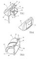
- Fig. 1
- shows a perspective view of the backside of an inventive neck rest with a support flap turned outwards.
- Fig. 2
- shows a view similar to Fig. 1, but with the support flap turned inwards.
- Fig. 3
- shows a perspective view of a casing for the support flap of Fig. 1.
- Fig. 4
- shows a perspective enlarged view of the support flap of Fig. 1.
- Fig. 5
- shows the rear view of the casing of Fig. 3.
- Fig. 6
- shows a perspective bottom view of the casing of Figs. 3 and 5.
- Fig. 7
- shows the rear view of the support flap of Fig. 4.
- Fig. 8
- shows a plug-in member with a hook for the support flap of Figs. 3 and 7.
- Fig. 9
- shows a plug-in member with a coat-hanger for the support flap of Figs. 3 and 7.
- Fig. 10
- shows how to attach the member of Fig. 9 to a neck rest body.
Claims (19)
- A neck rest for the front seats in automobiles, a neck rest body being supported by the back rest of the front seats, characterized in that a support member being integrated in the backside of the neck rest body (12), the support member being movable in the neck rest body (12) between a closed and an opened position, in the closed position the support member being substantially flush with the backside of the neck rest body (12) and the support member having means for supporting or suspending an article at the backside of the neck rest body in the opened position of the support member (12).
- The neck rest of claim 1, wherein the support member includes a support flap (22) supported for rotation about a horizontal axis, in the opened position the support flap being extended substantially horizontally.
- The neck rest of claim 1, wherein the support member is retained in the closed position by locking means.
- The neck rest of claim 3, wherein the locking means is designed along the push-push-principle such that an upon a pressure against the backside of the support member the locking means is unlocked and the support member is automatically locked when moved from the opened to the closed position.
- The neck rest of claim 3, wherein at the backside of the neck rest body (12) or of the support member an actuation element is provided which an upon actuation unlocks the locking means.
- The neck rest according to claim 1, wherein the support member is biased to the opened position by spring means.
- The neck rest of claim 6, wherein the support member cooperates with a dampening element if moved into the opened position.
- The neck rest of claim 1, wherein the support member and the neck rest body (12) include cooperating retaining means to hold the support member in the opened position.
- The neck rest of claim 8, wherein on each site of the support member a retaining element is provided.
- The neck rest of claim 1, wherein on the inner side of the support member separate means for supporting or suspending are releasably attached.
- The neck rest of claim 10, wherein plug-in means are provided for plugging the suspension or supporting means into accommodation means on the support member.
- The neck rest of claim 10 or 11, wherein the suspension or supporting means are releasably attachable or pluggable.
- The neck rest of claim 1, wherein suspension or supporting means are displaceably supported on the support member such that in the opened position of the support member the suspension or supporting means can be displaced partially beyond the outer edge of the support member.
- The neck rest of claim 10, wherein the suspension or supporting means include a hook (76)
- The neck rest of claim 10 or 11, wherein the suspension or supporting means include a coat-hanger (82).
- The neck rest of claim 2, wherein the support flap (22) has vertical lateral portions (26, 28), a housing (40) is adapted to be mounted in the neck rest body (12), the housing having a backwardly directed opening (50), a bottom (42) and side walls (44, 46), a journal being provided between the side walls (44, 46) and the lateral portions (26, 28) of the support flap and guide means are provided between the side walls (44, 46) in the lateral portions (26, 28) which guide the support flap (22) during its displacement and limit the movement thereof.
- The neck rest of claim 16, wherein the side walls (44, 46) have arcuate guide slots (60) and the lateral portions (26, 28) each have a projection (62, 64) which engages the associated guide slot.
- The neck rest of claim 16 or 17, wherein the lateral portions (26, 28) of the support flap (22) are interconnected by a transverse element or a rear wall portion (30) a locking element (70) being movably supported by the transverse element or the rear wall (30) the locking element cooperating with a locking recess in the rear wall (48) of housing (40).
- The neck rest of claim 11, wherein the supporting or suspension means are mounted to the front side of the rear wall (30) of the support flap (22).
Applications Claiming Priority (2)
| Application Number | Priority Date | Filing Date | Title |
|---|---|---|---|
| DE102004016255A DE102004016255B8 (en) | 2004-04-02 | 2004-04-02 | Headrest for the front seats of automobiles |
| DE102004016255 | 2004-04-02 |
Publications (3)
| Publication Number | Publication Date |
|---|---|
| EP1582400A2 true EP1582400A2 (en) | 2005-10-05 |
| EP1582400A3 EP1582400A3 (en) | 2007-02-14 |
| EP1582400B1 EP1582400B1 (en) | 2008-05-28 |
Family
ID=34745460
Family Applications (1)
| Application Number | Title | Priority Date | Filing Date |
|---|---|---|---|
| EP05002748A Expired - Fee Related EP1582400B1 (en) | 2004-04-02 | 2005-02-10 | A neck rest for the front seats of automobiles |
Country Status (4)
| Country | Link |
|---|---|
| US (1) | US7213877B2 (en) |
| EP (1) | EP1582400B1 (en) |
| DE (2) | DE102004016255B8 (en) |
| ES (1) | ES2307081T3 (en) |
Cited By (4)
| Publication number | Priority date | Publication date | Assignee | Title |
|---|---|---|---|---|
| US7407231B2 (en) | 2004-05-14 | 2008-08-05 | Alfmeier Prazision Ag Baugruppen Und Systemlosungen | Vehicle seat with a headrest and headrest adjustment assembly |
| US7429082B2 (en) | 2004-03-19 | 2008-09-30 | Alfmeier Prazision Ag Baugruppen Und Systemlosungen | Vehicle seat with a pivotally installed headrest |
| US7600818B2 (en) | 2003-01-10 | 2009-10-13 | Alfmeier Prazision Ag Baugruppen und Systemlosung | Fastening device for the headrest of a vehicle seat |
| US7753683B2 (en) | 2007-01-31 | 2010-07-13 | Alfmeier Prazision AG Baungruppen und Sysemlosungen | Headrest system for a vehicle seat |
Families Citing this family (17)
| Publication number | Priority date | Publication date | Assignee | Title |
|---|---|---|---|---|
| JP4647331B2 (en) * | 2004-03-23 | 2011-03-09 | 株式会社東洋シート | Vehicle seat with headrest |
| US7462903B1 (en) * | 2005-09-14 | 2008-12-09 | Spansion Llc | Methods for fabricating semiconductor devices and contacts to semiconductor devices |
| DE102006026840A1 (en) * | 2006-06-09 | 2007-12-13 | GM Global Technology Operations, Inc., Detroit | Headrest of a vehicle seat with a container |
| US20080229492A1 (en) * | 2007-03-22 | 2008-09-25 | Victoria Jamieson | Reclining foldable shampoo chair for a bath |
| US7669821B2 (en) * | 2007-10-02 | 2010-03-02 | Honda Motor Co., Ltd | Retractable accessory hook for a vehicle |
| DE102008013123A1 (en) * | 2008-03-07 | 2009-09-10 | GM Global Technology Operations, Inc., Detroit | Headrest for e.g. driver seat of passenger car, has retaining area accommodating utensils, and cover for closing retaining area and accommodating hanger parts that are arranged in inner area of retaining area in closed position of cover |
| US7832794B2 (en) * | 2009-02-17 | 2010-11-16 | Honda Motor Co., Ltd. | Vehicle with hidden pillows for bed mode |
| EP2414232B1 (en) * | 2009-03-30 | 2013-05-01 | Weber Aircraft LLC | Amenity pocket |
| US9283876B2 (en) * | 2012-03-02 | 2016-03-15 | GM Global Technology Operations LLC | Head restraint with storage |
| DE102013225663B4 (en) | 2013-12-11 | 2018-09-13 | Volkswagen Aktiengesellschaft | Vehicle seat with a fold-down backrest |
| CN104129340B (en) * | 2014-07-04 | 2016-05-25 | 梁荣铿 | A kind of plastic bag handheld combination unit that is fixed on motor vehicle seat back |
| US9216676B1 (en) * | 2014-07-11 | 2015-12-22 | Ford Global Technologies, Llc | Seat assembly with displaceable neckrest and neck support |
| TWI628095B (en) * | 2014-11-19 | 2018-07-01 | 鴻海精密工業股份有限公司 | Fixing device and car seat using the same |
| US10093205B2 (en) | 2015-08-18 | 2018-10-09 | Ford Global Technologies, Llc | Head rest with a compartment for a travel pillow |
| US10220790B2 (en) * | 2017-01-26 | 2019-03-05 | Ford Global Technologies, Llc | Pivoting hanger with positive retention |
| US10703485B2 (en) * | 2018-03-19 | 2020-07-07 | The Boeing Company | Transformable headrest for aircraft seating |
| DE102019101553A1 (en) * | 2019-01-23 | 2020-07-23 | Kinetix Ag | Motor vehicle seat arrangement |
Citations (7)
| Publication number | Priority date | Publication date | Assignee | Title |
|---|---|---|---|---|
| FR2380161A1 (en) * | 1977-02-11 | 1978-09-08 | Tis Srl | Vehicle front seat headrest - has foam rubber lining on front of rigid body with opening at rear to form storage space |
| EP0753427A2 (en) * | 1995-07-14 | 1997-01-15 | Innovations Ltd. | Hanger form handgrip for automotive vehicles with an apparatus for hanging clothes |
| WO1997003864A1 (en) * | 1995-07-21 | 1997-02-06 | Ctech Ag | Device for hanging up items of clothing |
| FR2773121A1 (en) * | 1997-12-30 | 1999-07-02 | Peugeot | Combined head rest and coat hanger for vehicle seat |
| DE19909879A1 (en) * | 1999-03-06 | 1999-09-23 | Audi Ag | Clothes hook for interior of vehicle |
| JP2002144966A (en) * | 2000-11-13 | 2002-05-22 | Nifco Inc | On-vehicle clothes hanger |
| DE20301090U1 (en) * | 2003-01-23 | 2003-05-08 | Meier Rudolf | Clothes hanger attached to automotive headrest support frame |
Family Cites Families (12)
| Publication number | Priority date | Publication date | Assignee | Title |
|---|---|---|---|---|
| US2320215A (en) * | 1941-10-17 | 1943-05-25 | Brenner Irving | Clothes compartment for vehicle seats |
| US2383125A (en) * | 1942-05-13 | 1945-08-21 | Hill Joanna | Railroad seat |
| US2951531A (en) * | 1958-06-24 | 1960-09-06 | Dantes Edna Merle | Home shampoo chair |
| US3615118A (en) * | 1968-12-04 | 1971-10-26 | Autair Int Airways Ltd | Installations for food catering |
| US4702519A (en) * | 1984-07-02 | 1987-10-27 | Irvin Industries, Inc. | Vanity mirror |
| US4711488A (en) * | 1986-08-22 | 1987-12-08 | Stephen Ohanessian | Garment hanger |
| US4792183A (en) * | 1987-10-29 | 1988-12-20 | Townsend Iii William R | Desk for use in automobiles |
| US4836602A (en) * | 1988-09-23 | 1989-06-06 | The Boeing Company | Apparatus for storing food and beverages in a passenger seatback |
| US5139310A (en) * | 1991-04-16 | 1992-08-18 | Tachi-S Co., Ltd. | Headrest |
| DE29616852U1 (en) * | 1996-09-27 | 1997-01-23 | Bjp Promotion Unternehmensbera | Integrated vehicle cloakroom (device for hanging clothes hangers with appropriate cloakroom behind the vehicle seat that can be integrated into each headrest) |
| DE29920466U1 (en) * | 1999-11-20 | 2000-01-13 | Faure Bertrand Sitztech Gmbh | Motor vehicle seat with a hanging element for clothing |
| US20030184134A1 (en) * | 2002-04-01 | 2003-10-02 | Liu Da Dun | Chair in combination with a hanger |
-
2004
- 2004-04-02 DE DE102004016255A patent/DE102004016255B8/en not_active Expired - Fee Related
-
2005
- 2005-02-10 DE DE602005007087T patent/DE602005007087D1/en not_active Expired - Fee Related
- 2005-02-10 EP EP05002748A patent/EP1582400B1/en not_active Expired - Fee Related
- 2005-02-10 ES ES05002748T patent/ES2307081T3/en active Active
- 2005-03-23 US US11/086,329 patent/US7213877B2/en not_active Expired - Fee Related
Patent Citations (7)
| Publication number | Priority date | Publication date | Assignee | Title |
|---|---|---|---|---|
| FR2380161A1 (en) * | 1977-02-11 | 1978-09-08 | Tis Srl | Vehicle front seat headrest - has foam rubber lining on front of rigid body with opening at rear to form storage space |
| EP0753427A2 (en) * | 1995-07-14 | 1997-01-15 | Innovations Ltd. | Hanger form handgrip for automotive vehicles with an apparatus for hanging clothes |
| WO1997003864A1 (en) * | 1995-07-21 | 1997-02-06 | Ctech Ag | Device for hanging up items of clothing |
| FR2773121A1 (en) * | 1997-12-30 | 1999-07-02 | Peugeot | Combined head rest and coat hanger for vehicle seat |
| DE19909879A1 (en) * | 1999-03-06 | 1999-09-23 | Audi Ag | Clothes hook for interior of vehicle |
| JP2002144966A (en) * | 2000-11-13 | 2002-05-22 | Nifco Inc | On-vehicle clothes hanger |
| DE20301090U1 (en) * | 2003-01-23 | 2003-05-08 | Meier Rudolf | Clothes hanger attached to automotive headrest support frame |
Cited By (4)
| Publication number | Priority date | Publication date | Assignee | Title |
|---|---|---|---|---|
| US7600818B2 (en) | 2003-01-10 | 2009-10-13 | Alfmeier Prazision Ag Baugruppen und Systemlosung | Fastening device for the headrest of a vehicle seat |
| US7429082B2 (en) | 2004-03-19 | 2008-09-30 | Alfmeier Prazision Ag Baugruppen Und Systemlosungen | Vehicle seat with a pivotally installed headrest |
| US7407231B2 (en) | 2004-05-14 | 2008-08-05 | Alfmeier Prazision Ag Baugruppen Und Systemlosungen | Vehicle seat with a headrest and headrest adjustment assembly |
| US7753683B2 (en) | 2007-01-31 | 2010-07-13 | Alfmeier Prazision AG Baungruppen und Sysemlosungen | Headrest system for a vehicle seat |
Also Published As
| Publication number | Publication date |
|---|---|
| EP1582400B1 (en) | 2008-05-28 |
| DE102004016255B8 (en) | 2005-12-15 |
| ES2307081T3 (en) | 2008-11-16 |
| EP1582400A3 (en) | 2007-02-14 |
| US20050218708A1 (en) | 2005-10-06 |
| US7213877B2 (en) | 2007-05-08 |
| DE602005007087D1 (en) | 2008-07-10 |
| DE102004016255B3 (en) | 2005-08-11 |
Similar Documents
| Publication | Publication Date | Title |
|---|---|---|
| EP1582400B1 (en) | A neck rest for the front seats of automobiles | |
| US5743585A (en) | Truck cab console with integral trash container | |
| US5104083A (en) | Automotive clothes hanger bracket | |
| CN206426948U (en) | Multifunctional hanging hook assembly and cargo management system for motor vehicles | |
| US5058790A (en) | Seat-mounted clothing valet | |
| GB2544180A (en) | Cover means and method of use thereof | |
| RU2698617C2 (en) | Cup holder system (embodiments) for motor vehicle | |
| US4444344A (en) | Hanger support | |
| US20080156837A1 (en) | Automobile garment hanging device | |
| US2447908A (en) | Folding clothes rack for automobiles | |
| JP3611751B2 (en) | Sliding console box | |
| CN210733989U (en) | Vehicle seat assembly and vehicle | |
| US3386589A (en) | Hanger apparatus for use in moving vehicles | |
| US7204463B2 (en) | Balancer device for hanging article | |
| US20090266858A1 (en) | Glove box door tethered utility hook | |
| JP3684960B2 (en) | Clothes hanger hanger | |
| KR20120076302A (en) | Retractable vehicle seat clothes hanging bar | |
| US20120085799A1 (en) | Clothing hanger device for vehicle deck lid | |
| US20050012351A1 (en) | Functional device for a motor vehicle loading area | |
| EP2177419B1 (en) | Stroller | |
| JP4757014B2 (en) | Goods holding tool | |
| JPS6317720Y2 (en) | ||
| JP3007706U (en) | Car accessory holder | |
| JP3697596B2 (en) | Console Box | |
| JP3007837U (en) | Car accessory holder |
Legal Events
| Date | Code | Title | Description |
|---|---|---|---|
| PUAI | Public reference made under article 153(3) epc to a published international application that has entered the european phase |
Free format text: ORIGINAL CODE: 0009012 |
|
| 17P | Request for examination filed |
Effective date: 20050223 |
|
| AK | Designated contracting states |
Kind code of ref document: A2 Designated state(s): AT BE BG CH CY CZ DE DK EE ES FI FR GB GR HU IE IS IT LI LT LU MC NL PL PT RO SE SI SK TR |
|
| AX | Request for extension of the european patent |
Extension state: AL BA HR LV MK YU |
|
| PUAL | Search report despatched |
Free format text: ORIGINAL CODE: 0009013 |
|
| AK | Designated contracting states |
Kind code of ref document: A3 Designated state(s): AT BE BG CH CY CZ DE DK EE ES FI FR GB GR HU IE IS IT LI LT LU MC NL PL PT RO SE SI SK TR |
|
| AX | Request for extension of the european patent |
Extension state: AL BA HR LV MK YU |
|
| 17Q | First examination report despatched |
Effective date: 20070427 |
|
| AKX | Designation fees paid |
Designated state(s): DE ES FR GB IT |
|
| GRAP | Despatch of communication of intention to grant a patent |
Free format text: ORIGINAL CODE: EPIDOSNIGR1 |
|
| GRAS | Grant fee paid |
Free format text: ORIGINAL CODE: EPIDOSNIGR3 |
|
| GRAA | (expected) grant |
Free format text: ORIGINAL CODE: 0009210 |
|
| AK | Designated contracting states |
Kind code of ref document: B1 Designated state(s): DE ES FR GB IT |
|
| REG | Reference to a national code |
Ref country code: GB Ref legal event code: FG4D |
|
| REF | Corresponds to: |
Ref document number: 602005007087 Country of ref document: DE Date of ref document: 20080710 Kind code of ref document: P |
|
| REG | Reference to a national code |
Ref country code: ES Ref legal event code: FG2A Ref document number: 2307081 Country of ref document: ES Kind code of ref document: T3 |
|
| PLBE | No opposition filed within time limit |
Free format text: ORIGINAL CODE: 0009261 |
|
| STAA | Information on the status of an ep patent application or granted ep patent |
Free format text: STATUS: NO OPPOSITION FILED WITHIN TIME LIMIT |
|
| PGFP | Annual fee paid to national office [announced via postgrant information from national office to epo] |
Ref country code: ES Payment date: 20090226 Year of fee payment: 5 |
|
| 26N | No opposition filed |
Effective date: 20090303 |
|
| PGFP | Annual fee paid to national office [announced via postgrant information from national office to epo] |
Ref country code: GB Payment date: 20090227 Year of fee payment: 5 |
|
| PGFP | Annual fee paid to national office [announced via postgrant information from national office to epo] |
Ref country code: DE Payment date: 20090331 Year of fee payment: 5 Ref country code: IT Payment date: 20090224 Year of fee payment: 5 |
|
| PGFP | Annual fee paid to national office [announced via postgrant information from national office to epo] |
Ref country code: FR Payment date: 20090217 Year of fee payment: 5 |
|
| GBPC | Gb: european patent ceased through non-payment of renewal fee |
Effective date: 20100210 |
|
| REG | Reference to a national code |
Ref country code: FR Ref legal event code: ST Effective date: 20101029 |
|
| PG25 | Lapsed in a contracting state [announced via postgrant information from national office to epo] |
Ref country code: FR Free format text: LAPSE BECAUSE OF NON-PAYMENT OF DUE FEES Effective date: 20100301 |
|
| PG25 | Lapsed in a contracting state [announced via postgrant information from national office to epo] |
Ref country code: DE Free format text: LAPSE BECAUSE OF NON-PAYMENT OF DUE FEES Effective date: 20100901 |
|
| REG | Reference to a national code |
Ref country code: ES Ref legal event code: FD2A Effective date: 20110309 |
|
| PG25 | Lapsed in a contracting state [announced via postgrant information from national office to epo] |
Ref country code: IT Free format text: LAPSE BECAUSE OF NON-PAYMENT OF DUE FEES Effective date: 20100210 Ref country code: GB Free format text: LAPSE BECAUSE OF NON-PAYMENT OF DUE FEES Effective date: 20100210 |
|
| PG25 | Lapsed in a contracting state [announced via postgrant information from national office to epo] |
Ref country code: ES Free format text: LAPSE BECAUSE OF NON-PAYMENT OF DUE FEES Effective date: 20110308 |
|
| PG25 | Lapsed in a contracting state [announced via postgrant information from national office to epo] |
Ref country code: ES Free format text: LAPSE BECAUSE OF NON-PAYMENT OF DUE FEES Effective date: 20100211 |