EP1553479A2 - Input mode selection on a palmtop computer - Google Patents
Input mode selection on a palmtop computer Download PDFInfo
- Publication number
- EP1553479A2 EP1553479A2 EP05075916A EP05075916A EP1553479A2 EP 1553479 A2 EP1553479 A2 EP 1553479A2 EP 05075916 A EP05075916 A EP 05075916A EP 05075916 A EP05075916 A EP 05075916A EP 1553479 A2 EP1553479 A2 EP 1553479A2
- Authority
- EP
- European Patent Office
- Prior art keywords
- input
- mode
- user
- palmtop computer
- modes
- Prior art date
- Legal status (The legal status is an assumption and is not a legal conclusion. Google has not performed a legal analysis and makes no representation as to the accuracy of the status listed.)
- Ceased
Links
Images


Classifications
-
- G—PHYSICS
- G06—COMPUTING; CALCULATING OR COUNTING
- G06F—ELECTRIC DIGITAL DATA PROCESSING
- G06F3/00—Input arrangements for transferring data to be processed into a form capable of being handled by the computer; Output arrangements for transferring data from processing unit to output unit, e.g. interface arrangements
- G06F3/01—Input arrangements or combined input and output arrangements for interaction between user and computer
- G06F3/016—Input arrangements with force or tactile feedback as computer generated output to the user
-
- G—PHYSICS
- G06—COMPUTING; CALCULATING OR COUNTING
- G06F—ELECTRIC DIGITAL DATA PROCESSING
- G06F1/00—Details not covered by groups G06F3/00 - G06F13/00 and G06F21/00
- G06F1/16—Constructional details or arrangements
- G06F1/1613—Constructional details or arrangements for portable computers
- G06F1/1626—Constructional details or arrangements for portable computers with a single-body enclosure integrating a flat display, e.g. Personal Digital Assistants [PDAs]
-
- G—PHYSICS
- G06—COMPUTING; CALCULATING OR COUNTING
- G06F—ELECTRIC DIGITAL DATA PROCESSING
- G06F1/00—Details not covered by groups G06F3/00 - G06F13/00 and G06F21/00
- G06F1/16—Constructional details or arrangements
- G06F1/1613—Constructional details or arrangements for portable computers
- G06F1/1633—Constructional details or arrangements of portable computers not specific to the type of enclosures covered by groups G06F1/1615 - G06F1/1626
- G06F1/1662—Details related to the integrated keyboard
- G06F1/1671—Special purpose buttons or auxiliary keyboards, e.g. retractable mini keypads, keypads or buttons that remain accessible at closed laptop
-
- G—PHYSICS
- G06—COMPUTING; CALCULATING OR COUNTING
- G06F—ELECTRIC DIGITAL DATA PROCESSING
- G06F1/00—Details not covered by groups G06F3/00 - G06F13/00 and G06F21/00
- G06F1/16—Constructional details or arrangements
- G06F1/1613—Constructional details or arrangements for portable computers
- G06F1/1633—Constructional details or arrangements of portable computers not specific to the type of enclosures covered by groups G06F1/1615 - G06F1/1626
- G06F1/1684—Constructional details or arrangements related to integrated I/O peripherals not covered by groups G06F1/1635 - G06F1/1675
- G06F1/169—Constructional details or arrangements related to integrated I/O peripherals not covered by groups G06F1/1635 - G06F1/1675 the I/O peripheral being an integrated pointing device, e.g. trackball in the palm rest area, mini-joystick integrated between keyboard keys, touch pads or touch stripes
-
- G—PHYSICS
- G06—COMPUTING; CALCULATING OR COUNTING
- G06F—ELECTRIC DIGITAL DATA PROCESSING
- G06F3/00—Input arrangements for transferring data to be processed into a form capable of being handled by the computer; Output arrangements for transferring data from processing unit to output unit, e.g. interface arrangements
- G06F3/01—Input arrangements or combined input and output arrangements for interaction between user and computer
- G06F3/011—Arrangements for interaction with the human body, e.g. for user immersion in virtual reality
-
- G—PHYSICS
- G06—COMPUTING; CALCULATING OR COUNTING
- G06F—ELECTRIC DIGITAL DATA PROCESSING
- G06F3/00—Input arrangements for transferring data to be processed into a form capable of being handled by the computer; Output arrangements for transferring data from processing unit to output unit, e.g. interface arrangements
- G06F3/01—Input arrangements or combined input and output arrangements for interaction between user and computer
- G06F3/02—Input arrangements using manually operated switches, e.g. using keyboards or dials
- G06F3/023—Arrangements for converting discrete items of information into a coded form, e.g. arrangements for interpreting keyboard generated codes as alphanumeric codes, operand codes or instruction codes
- G06F3/0233—Character input methods
- G06F3/0234—Character input methods using switches operable in different directions
-
- G—PHYSICS
- G06—COMPUTING; CALCULATING OR COUNTING
- G06F—ELECTRIC DIGITAL DATA PROCESSING
- G06F3/00—Input arrangements for transferring data to be processed into a form capable of being handled by the computer; Output arrangements for transferring data from processing unit to output unit, e.g. interface arrangements
- G06F3/01—Input arrangements or combined input and output arrangements for interaction between user and computer
- G06F3/03—Arrangements for converting the position or the displacement of a member into a coded form
- G06F3/033—Pointing devices displaced or positioned by the user, e.g. mice, trackballs, pens or joysticks; Accessories therefor
- G06F3/0354—Pointing devices displaced or positioned by the user, e.g. mice, trackballs, pens or joysticks; Accessories therefor with detection of 2D relative movements between the device, or an operating part thereof, and a plane or surface, e.g. 2D mice, trackballs, pens or pucks
- G06F3/03545—Pens or stylus
-
- G—PHYSICS
- G06—COMPUTING; CALCULATING OR COUNTING
- G06F—ELECTRIC DIGITAL DATA PROCESSING
- G06F3/00—Input arrangements for transferring data to be processed into a form capable of being handled by the computer; Output arrangements for transferring data from processing unit to output unit, e.g. interface arrangements
- G06F3/01—Input arrangements or combined input and output arrangements for interaction between user and computer
- G06F3/03—Arrangements for converting the position or the displacement of a member into a coded form
- G06F3/033—Pointing devices displaced or positioned by the user, e.g. mice, trackballs, pens or joysticks; Accessories therefor
- G06F3/0354—Pointing devices displaced or positioned by the user, e.g. mice, trackballs, pens or joysticks; Accessories therefor with detection of 2D relative movements between the device, or an operating part thereof, and a plane or surface, e.g. 2D mice, trackballs, pens or pucks
- G06F3/03547—Touch pads, in which fingers can move on a surface
-
- G—PHYSICS
- G06—COMPUTING; CALCULATING OR COUNTING
- G06F—ELECTRIC DIGITAL DATA PROCESSING
- G06F2203/00—Indexing scheme relating to G06F3/00 - G06F3/048
- G06F2203/01—Indexing scheme relating to G06F3/01
- G06F2203/014—Force feedback applied to GUI
-
- G—PHYSICS
- G06—COMPUTING; CALCULATING OR COUNTING
- G06F—ELECTRIC DIGITAL DATA PROCESSING
- G06F2203/00—Indexing scheme relating to G06F3/00 - G06F3/048
- G06F2203/048—Indexing scheme relating to G06F3/048
- G06F2203/04809—Textured surface identifying touch areas, e.g. overlay structure for a virtual keyboard
Definitions
- the present invention relates to the field of palmtop computers and more particularly, though not solely, to the selection of input modes for entering alpha-numeric characters on palmtop computers.
- the palmtop computer has evolved as a portable device which provides for easy storage, organization, and recollection of information.
- Palmtop computers are small, compact computers that generally fit in the palm of a person's hand.
- the palmtop computer allows for easy operation, as a user simply holds the palmtop computer in one hand (the "non-writing hand") while entering information with the other hand (the "writing hand”). Because of the small size of the palmtop computer, the user may simply place the device in a pocket or briefcase when not in use.
- Conventional palmtop computers generally employ a digitizer pad upon which a user may write with a pen or finger.
- a handwriting recognition system is generally incorporated to recognize strokes and presses made by the user upon the digitizer pad as individual characters. The handwritten characters are then converted into a machine-readable format such as ASCII code.
- one node allows for only lowercase letters to be input (“alpha mode”)
- a second mode is for only uppercase letters (“caps mode”)
- a third mode is for numbers (“numeric mode”)
- a fourth mode is for punctuation (“punctuation mode”) .
- alpha mode the number of possible characters which may be confused for a particular stroke is greatly reduced. For example, if alpha mode is selected, the recognition system will not recognize the letter “s” as the number "5.” similarly, a lowercase "c” will not be recognized as an uppercase “C.”
- Selecting and switching among various input modes using conventional means takes time and effort on the part of the user.
- the user must take some action to switch from one mode to another, in addition to the strokes and motions he would otherwise have to make to input the actual characters.
- some conventional schemes involve the use of "mode change" strokes which the user makes on the digitizer pad to change input modes. These mode change strokes must be interspersed with strokes the user ordinarily would make to enter characters.
- Such systems present various problems. Additional time is required to make the mode change strokes.
- the mode change strokes themselves are often confused for input characters. Also, it is often not immediately clear to the user which input mode is being used. The particular mode may be displayed on a display area of the digitzer pad, but the user must still look at the device to determine which mode is active.
- the present invention relates to a palmtop computer. Characters may be entered using one or more input modes.
- the computer includes a casing and a digitizer pad coupled to the casing.
- a border is formed around the digitizer pad.
- the border includes a ridge coupled to select an input mode.
- a palmtop computer for receiving input of characters comprises a casing, a digitizer pad coupled to the casing and a border formed around the digitizer pad, the border including an actuable ridge to select a character type input mode, wherein said actuable ridge includes a stepped inner edge that is actuable by applying a pressure to said stepped inner edge to select a character type input mode.
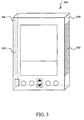
- Fig. 1a shows a palmtop computer 100 which includes a casing 108 made of plastic or any suitable material.
- Casing 108 has a front panel 110, a left side panel 112, a right side panel 114 and a back panel.
- Fitted to front panel 110 is a touch sensitive digitizer pad 103 which is capable of detecting presses and movements of a pen or finger.
- digitizer pad 103 covers a display screen 102 and a user input area 104.
- Display screen 102 displays information to a user.
- User input area 104 is used to input text.
- digitizer pad 103 covers only user input area 104.
- digitizer pad 103 covers a homogenous area which serves as both a display screen and user input area. Other assignments of areas to regions under digitizer pad 103 may be used as should be recognized by those skilled in the art.
- palmtop computer 100 includes a plurality of mechanical buttons 106a-106g mounted to front panel 110. Buttons 106a-106g provide the user with various functions for operating palmtop computer 100. In the embodiment of Fig. 1a, button 106a is a power button. Buttons 106d and 106e are bi-directional scrolling buttons used to scroll up and down through information shown on display area 102.
- Buttons 106b, 106c, 106f, and 106g are application buttons.
- application button 106b is used for a calendar application
- application button 106c is used for an address book application
- application button 106f is used for a to-do list application
- application button 106g is used for a note pad application.
- Other applications may be associated with these buttons as will be understood by one skilled in the art.
- buttons 106b, 106c, 106f, and 106g are generic application buttons which are programmable by the user. Various applications may be assigned to the buttons as designated by the user.
- palmtop computer 100 when palmtop computer 100 is powered off, pressing any one of application buttons 106b, 106c, 106f, and 106g generates a hardware interrupt signal which is sent to a processor within palmtop computer 100.
- the hardware interrupt signal "wakes” the processor in the palmtop computer 100 from a "sleep” mode and causes the processor to execute code in a "wake-up" routine. In the wake-up routine, the processor checks a register to determine which application button was pressed.
- the default input mode for inputting text in input area 104 is generally alpha mode, although other modes may be programmed by the user as the default input mode. These include but are not limited to caps mode, numeric mode, and punctuation mode.
- exemplary embodiments of the present invention provide for the selection of input modes using the non-writing hand.
- Some of these embodiments involve one or more physical sensors mounted on the casing of the palmtop computer.
- the physical sensors are preferably positioned along the sides of the casing to facilitate use by left-handed and right-handed persons.
- physical sensors for both types of users are mounted on the same casing.
- the physical sensor is positioned for use by either left-handed or right-handed users.
- the sensor is mounted on one side of the device for control by one hand, but the user can rotate the device 180 degrees to control the device with the other hand.
- a mechanical button 118 is mounted to casing 108 on right panel 114.
- the button 118 is preferably positioned along the length of right panel 114 proximate the position of the forefinger or middle finger of a right-handed user's left hand when holding the device, to facilitate easy switching between modes.
- a left-handed user may use the same device and switch modes with the thumb of his right hand.
- button 118 is positioned along left panel 112 of casing 108, rather than right panel 114. Such is desirable for the left-handed user who holds palmtop computer 100 with his right hand. The user may then operate button 118 with the forefinger or middle finger of his right hand.
- button 118 is coupled to the processor within palmtop computer 100. Pressing button 118 sends a signal to the processor instructing the processor to select an input mode.
- software programmed into the processor is used to identify the selection of input modes. In one example, pressing button 118 sends a signal to a register to change one or more status bits representing the particular input mode. Responsive to some external action like lifting the pen, the software checks the status bit and selects the input mode accordingly. In another example, the software simply checks the status bit periodically to determine the input mode. Other implementations for coupling button 118 to select input modes will be recognized by one skilled in the art.
- Particular input modes are selected by pressing mechanical button 118.
- successively pressing mechanical button 118 causes computer 100 to cycle through the available input modes: caps, numeric, punctuation, alpha, caps, numeric, etc.
- specific combinations or sequences of motions cause system 100 to select particular modes. For example, a press and hold selects caps mode, similar to a "CAPS" key on a typewriter. A double press and hold selects numeric mode. When the button is released, the device returns to alpha mode.
- Other implementations may be used as should be recognized by the skilled artisan.
- Fig. 1b is a top view of a plurality of mechanical buttons 122, 124, 126, 128 which are mounted to palmtop computer 100.
- the buttons are mounted along side panel 114 of casing 108, preferably proximate the user's fingers when holding the device.
- Each of the four mechanical buttons is assigned a particular input mode.
- button 122 is designated as alpha mode
- button 124 is for caps mode
- button 126 is for numeric mode
- button 128 is for punctuation mode.
- Each of the buttons is coupled to select input modes similar to button 118 of Fig. 1a. In this way, pressing any one of the buttons switches to the respective input mode assigned to that button.
- Figs. 2a-2c illustrate another exemplary embodiment of a physical sensor constructed according to the present invention, in the form of a rocker switch 200.
- the rocker switch is preferably mounted on a side panel 114 or 112 of palmtop computer 100 and positioned along the side panel similar to mechanical button 118.
- the rocker switch 200 is coupled to select input modes for palmtop computer 100, using techniques described above with respect to Figs. 1a and 1b.
- switch 200 sits in a neutral position 202 when not acted upon by external forces.
- the user may force the switch into an "up” position 204 by rocking the switch in one direction with his finger.
- the user may also force the switch into a "down” position 206 by rocking the switch in the opposite direction.
- the switch springs back to neutral position 202 of Fig. 2a.
- alpha mode is selected as the input mode when rocker switch 200 is in neutral position 202.
- Moving rocker switch 200 to up position 204 changes modes to numeric mode.
- Rocking the switch 200 down switches to caps input mode.
- rocker switch 200 may also be pressed into panel 114 to define a "pressed" position 208. Pressing switch 200 in this manner selects another input mode, such as punctuation mode.
- the various switching configurations discussed above for mechanical button 118 are also applicable to rocker switch 200.
- Various other assignments of input modes to the available positions for rocker switch 200 are possible, as will be recognized by those skilled in the art.
- palmtop computer 300 includes a first pressure strip 302 mounted along first side panel 304 and a second pressure strip 306 mounted along second side panel 308.
- the pressure strips 302 and 306 are desirably located along the respective side panels such that one of the pressure strips is positioned under the user's fingers and the other pressure strip is positioned under the user's thumb when gripping the device.
- the pressure strips 302 and 306 are coupled to select input modes for palmtop computer 300 using hardware and/or software, in similar fashion as described above with respect to the embodiments of Figs. 1a-b, and 2a-c.
- the strips 302 and 306 are coupled such that the computer can detect the activation of both strips, corresponding to the user squeezing the sides of the device with his non-writing hand.
- only one pressure strip 302 is mounted on one side panal 304. Pressing the one strip 302, generally while gripping the other side panel 114, selects and switches between input modes.
- a dial 402 is mounted to side panel 114 of palmtop computer 100.
- the dial 402 is positioned along the side panel similar to mechanical button 118 of Fig. 1 or rocker switch 200 of Figs. 2a and 2b.
- Dial 402 sits in a neutral position 404 when not acted upon by external forces.
- the dial is moveable to an "up" position 406 by pressing the switch in one direction, and also to a "down" position 408 by pressing the switch in the opposite direction.
- the dial returns to neutral position 202.
- Fig. 4 is a side view of a dial 402, mounted to palmtop computer 100, constructed according to an exemplary embodiment of the present invention.
- Dial 402 is coupled to select input modes for palmtop computer 100 using similar techniques as described above.
- Dial 402 rests in a neutral position when not acted upon by external forces.
- Dial 402 may be rotated in one direction to define an "up" position and in the opposite direction to define a "down" position.
- the up and down positions are offset by about 15 degrees from neutral position.
- One or more springs are preferably incorporate to cause dial 402 to return to neutral position when the user releases the dial.
- dial 402 is configured, in one example, so that neutral position is associated with alpha mode. Moving dial 402 to the up position changes modes to numeric mode, and moving dial 402 to the down position changes the input mode to caps mode. Similar to rocker switch 200, dial 402 may be pressed into side panel 114 to define a pressed position 410 for switching to another input mode, such as punctuation mode.
- dial 402 may be pressed into side panel 114 to define a pressed position 410 for switching to another input mode, such as punctuation mode.
- a pressed position 410 for switching to another input mode, such as punctuation mode.
- the input area of the palmtop computer is divided into input mode regions for entering particular kinds of characters. Boundaries between these regions are often delineated by surface textures or ridges, described in more detail below. These boundaries are advantageous as they allow the user to "feel" his way from region to region as he moves a pen or his finger over the input area. The user can thus quickly and easily learn to associate particular input modes with the particular regions so that when using the device, the user will know the region in which he is entering characters without having to look at the device.
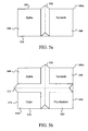
- a ridge 502 extends vertically across a user input area 500a of a palintop computer from a top side 508 to a bottom side 510 of input area 500a. In this way, ridge 502 defines a first input zone 504 and a second input zone 506. In an alternative embodiment, (not shown) ridge 502 extends horizontally along input area 500a such that input zones 504 and 506 are defined on upper and lower sides of ridge 502. Ridge 502 is preferably molded as part of the digitizer pad of input area 500a, although ridge 502 may also be formed separately of some suitable material such as plastic and affixed to the digitizer pad by an adhesive.
- first input zone 504 is designated as alpha mode
- second input zone 506 is designated as numeric mode.
- the palmtop computer is programmed so that the regions of the digitizer pad underlying these input zones recognize characters of only that particular mode. Other designations of particular modes may be defined by the user as desired.
- a physical sensor such as mechanical button 118 of Fig. 1 may be incorporated to provide for other modes of input. For example, a user may press mechanical button 118 to switch the designations of input zones 504 and 506 from alpha mode and numeric mode to caps mode and punctuation mode, respectively.
- Fig. 5b illustrates an incur area 500b, constructed according to a further exemplary embodiment of the present invention, incorporating a second ridge 512 passing across input area 500b from a left side 514 to a right side 516.
- second ridge 512 is used in conjunction with ridge 502
- four input zones are defined.
- zone 504 is for alpha mode
- zone 506 is for numeric mode
- zone 518 is for caps mode
- zone 520 is for punctuation mode.
- Other designations may be made, as will be recognized by those skilled in the art.
- Fig. 6a illustrates a user input area 600a with a border 602 formed around the input area.
- the border 602 includes a plurality of ridges 604, 606, 608, 610.
- a top ridge 604 is positioned along the top of input area 600a, and a bottom ridge 606 lies along the bottom of input area 600a.
- Left and right ridges 608 and 610 are positioned at the left and right sides of input area 600a, respectively.
- the ridges 604, 606, 608, 610 have stepped inner edges 612 to provide defined contact points for the user's pen or finger.
- each of the ridges is assigned a particular input mode.
- upper ridge 604 is assigned caps mode
- lower ridge 606 is assigned alpha mode.
- Left ridge 608 is assigned numeric mode
- right ridge 610 is assigned punctuation mode.
- Other assignments of particular modes to the individual ridges may be programmed by the user, as will be recognized by those skilled in the art. The user can then select the desired input mode by touching the appropriate ridge with the user's pen or finger.
- each ridge is made of a pressure sensitive material and coupled to the processor within the palmtop computer independently of the other ridges.
- a signal is communicated from that ridge to the processor to select a particular input mode.
- the selection may be made using software programmed into the processor, as described above.
- the ridges may be connected to one another at their respective ends or moveable independent from one another.
- each ridge is made of plastic or some similar material and flexible or moveable in a direction away from the opposite ridge on the other side of the input area.
- the ridges are preferably not connected to one another at their respective ends so the ridges can move independently of one another.
- Each of the ridges is positioned proximate to a pressure or contact sensor.
- the contact sensors are indemendently coupled to the palmtop computer processor.
- a spring or some other expandable device is preferably situated between each ridge and its associared sensor to separate the two during normal operation. To select an input mode, the user activates the appropriate sensor by touching the associated ridge and pressing it into contact with the sensor.
- user input area 600a further includes a relatively smaller inner border 613 formed inside border 602.
- the inner border 613 may be molded as part of the digitizer pad of input area 600a or formed separately and affixed to the digitizer pad.
- Inner border 613 is preferably shaped with graded or angled sides similar to ridges 502 and 512 of Figs. 5a and 5b, as opposed to the stepped inner edges 612 of border 602.
- the inner border 613 thus provides haptic feedback, as the user feels a slight bump when he drags his pen or finger over the inner border towards border 602. In this way, the user can recognize when he is approaching border 602 and avoid inadvertently touching one of ridges 604, 606, 608, 610 when he does not want to change input modes.
- Fig. 6b illustrates another exemplary user input area 600b incorporating border 602 of Fig. 6a for selecting input modes.
- Border 602 may be realized using the examples described above with respect to Fig. 6a.
- User input area 600b includes a textured region 616 formed around the input area proximate the ridges that comprise border 602. Textured region 616 provides haptic feedback similar to inner ridge 613. That is, the region provides a warning to the user when he drags his pen or finger close to any of the ridges. The user can recognize when he is approaching border 602 and avoid inadvertently touching one of the ridges to change input modes.
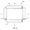
- Fig. 6c illustrates yet another exemplary user input area 600c incorporating ridges.
- a top ridge 620 is positioned along the top side of input area 600c
- a bottom ridge 622 is positioned along the bottom of input area 600c.
- Left and right ridges 624 and 626 are positioned at the left and right sides of input area 600c, respectively.
- ridges 620, 622, 624, and 626 are shaped with slanted sides similar to ridges 502 and 512 of Figs. 5a and 5b.
- the ridges of Fig. 6c are preferably moveable independent of one another.
- Each of ridges 620, 622, 624, and 626 is assigned a particular input mode and coupled to select the mode in similar fashion to the ridges of Figs. 6a and 6b.
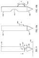
- FIG. 7a and 7b Other exemplary input areas 700a and 700b of palmtop computers constructed according to further embodiments of the present invention are shown in Figs. 7a and 7b, respectively.
- Input regions 700a and 700b have textured zones or regions to provide haptic feedback so the user can easily determine the region in which he is writing without having to look at the palmtop computer.
- input area 700a is divided into two input regions, input region 702 and input region 704.
- the respective regions are demarcated by different textures.
- input region 704 has a smooth texture and input region 702 has a relatively rough texture.
- the palmtop computer is programmed to recognize characters entered in input region 702 as being of one particular mode, and those entered in input region 704 as those of another input mode.
- alpha mode is assigned to input region 702, and numeric mode is assigned to input region 704.
- Other assignments of particular modes to regions 702, 704 may be made as understood by those skilled in the art.
- Fig. 7b input area 104 is divided into four regions to provide for additional input regions 706 and 708. Caps mode and punctuation mode are assigned to regions 706 and 708, respectively. Each of input regions 702, 704, 706 and 708 has a distinct texture to distinguish that region from the other regions.
- the surface textures of Fig. 7b provide haptic feedback as to the particular input region in which the user is writing, so the user can be looking at other things than the palmtop computer when entering characters.
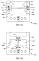
- Fig. 8a is a partial front view of a palmtop computer 800a constructed according to an exemplary embodiment of the present invention.
- the palmtop computer includes a casing 802 similar to casing 108 of palmtop computer 100 shown in Fig. 1.
- Fitted to casing 802 is a digitizer pad 803 having a left side 806 and a right side 808.
- a left trench 810 is formed in an inner wall of casing 802 proximate left side 806 of digitizer pad 803.
- the left trench 810 runs parallel to left side 806 of digitizer pad 803.
- a right trench 812 is formed in an inner wall of casing 802 proximate to right side 808 of digitizer pad 803 and runs parallel to right side 808.
- a moveable bar 814 is positioned across digitizer pad 803 to define a first input region 804a and a second input region 804b.
- the palmtop computer 800a is programmed to recognize characters input in region 804a as being of one particular mode such as alpha mode, and characters input in region 804b as of another mode such as caps mode.
- the bar 814 is made of plastic or any suitably rigid material. In one embodiment, bar 814 is in contact with the user input area, while in other embodiments bar 814 is floating above user input area 804 by the positioning of trenches 810 and 812.
- bar 814 has a left end 816 which fits in left trench 810 and a right end 818 which fits in right trench 812. Two springs are situated on either side of left end 816 in left trench 810. Similarly, two springs are situated on either side of right end 818 in right trench 812.
- a first pressure sensor 820 is positioned in left trench 810 as shown in Fig. 8a, and a second pressure sensor 822 is positioned as shown in Fig. 8a. Each pressure sensor 820, 822 is coupled to select and switch between modes of input using techniques described above.
- sensor 820 is used to cycle "up” through a series of input modes with successive presses (e.g., alpha, caps, numeric, punctuation, alpha, etc.), and sensor 822 is for cycling “down” through the input modes (e.g., alpha, punctuation, numeric, caps, alpha, etc.).
- Fig. 8b is a partial front view of another palmtop computer 800b constructed according to an exemplary embodiment of the present invention.
- Palmtop computer 800b is similar to computer 800a of Fig. 8a in most respects although, in Fig. 8b, moveable bar 852 is positioned across digitizer pad 823 substantially perpendicular with respect to bar 814 of Fig. 8a.
- a top trench 854 is formed in an inner wall of casing 802 proximate a top side 856 of digitizer pad 803.
- a bottom trench 858 is formed in an inner wall of casing 802 proximate to the bottom side 860 of digitizer pad 803.
- moveable bar 852 has ends which fit into trenches 854 and 858.
- a first input region 862a and a second input region 864b of digitizer pad 803 are defined.
- Input regions 862 and 864 are designated for entering characters using particular modes of input, similar to input regions 804a and 804b of Fig. 8a.
- Springs and pressure sensors are positioned in trench 858 similar to trench 810 of Fig. 8a for selecting and switching among various input modes.
- Fig. 9 illustrates an exemplary pen 900 for use as part of a palmtop computer system constructed in accordance with a further embodiment of the present invention.
- the pen 900 includes a retractable tip 902 which is shown in contact with the surface of digitizer pad 103 of the palmtop computer of Fig. 1.
- a switch 903 is mounted in an inner cavity 904 of pen 900.
- the switch 903 is in communication with the palmtop computer for selecting and switching among input modes.
- communications are supported by a wire coupled between the pen and the palmtop computer.
- wireless communications devices such as RF transmitters and receivers are employed to achieve communications between the pen and palmtop computer.
- tip 902 When pressure is exerted on pen 900 against the surface of digitizer pad 103, as shown in Fig. 9, tip 902 temporarily retracts into inner cavity 904 of pen 900 until the pressure is released. Retraction of tip 902 activates the switch in inner cavity 904, causing a signal to be sent from pen 900 to the palmtop computer.
- the signal calls for a particular input mode or changes from one input mode to another. Alternatively, the number of presses may signal a particular input mode.
- the magnitude of the pressure exerted on the pen controls which input mode is selected.
- a "hard" press signals the palmtop computer to change to caps mode.
- Two hard presses signals the palmtop computer to change to alpha mode.
- a relatively light press signifies numeric mode.
- the presses are made by tapping the pen on the casing.
- rhe presses are made while writing, preferably at the beginning of a stroke.
- a pressure sensor is mounted in inner cavity 904 instead of the switch to differentiate between the magnitudes of presses.
- a button 1004 is mounted on a pen 1002.
- Button 1004 is preferably positioned near a writing end 1006 of the pen, as shown in Fig. 10a, such that button 1004 is proximate the user's fingers or thumb when he grips the pen.
- Pressing the button toggles a switch inside pen 1002, causing a signal to be sent to the palmtop computer. Communications between the pen and the palmtop computer are established using techniques similar to those described above with respect to Figs. 9a and 9b. Successive presses of button 1004 cause the computer to cycle through the various input modes, similar to the implementation of mechanical button 118 of Figs. 1a and 1b. Other assignments of button presses and holds to select and switch input modes such as those described above with respect to other embodiments of the present invention, may be implemented as will be appreciated by one skilled in the art.
- a dial 1008 is mounted to the side of pen 1002 in place of button 1004. Rotating the dial causes the palmtop computer to cycle through the various input modes. Pressing dial 1008 selects a particular mode for inputting characters. Other techniques for assigning presses and rotations to select and switch input modes may be implemented as described above, particularly with reference to Figs. 4, 8a, 8b, and 9a.
- one or more accelerometers are preferably incorporated in the palmtop computer.
- the ADXL202 accelerometer manufactured by Analog Devices is one model which may be used, although other accelerometers may be used as will be appreciated by one skilled in the art.
- one or more ADXL202 accelerometers are mounted to casing 108 of palmtop computer 100 of Fig. 1.
- the accelerometer may be used in place of button 118.
- the accelerometer or accelerometers are positioned with respect to a longitudinal Y axis 140 and an X axis 142 substantially perpendicular to the Y axis for two-axis tilt sensing. In this way, for example, tilting the computer 100 in one direction (e.g., clockwise) with respect to Y axis 140 selects one input mode, while tilting the computer 100 in the other direction (e.g., counter-clockwise) with respect to Y axis 140 selects another input mode.
- tilting palmtop computer 100 about X axis 142 in clockwise or counter-clockwise directions selects additional input modes.
- additional accelerometers allows for the selection of additional input modes by tilting the device with respect to the X, Y and other axes.
- Various assignments of particular input modes to tilting directions may be made, as will be recognized by one skilled in the art.
- the accelerometer or accelerometers are coupled to select input modes using software and/or hardware configurations similar to those described above with respect to other exemplary embodiments of the present invention.
- digital X and Y output pins are provided which identify the most recent mode selected. These outputs may be coupled directly to the processor within palmtop computer 100 to select and switch input modes. Alternatively, the bits output on the X and Y pins may be clocked and stored as status bits in a register for software-controlled switching.
- audio feedback may be used to signal an input mode change to the user.
- a speaker mounted to the casing of the palmtop computer serves this purpose. The user can turn on or turn off the speaker, depending on the desired operating environment.
- a "beep" is emitted through the speaker anytime the input mode changes.
- beeps having different frequencies from one another are associated with the various input modes. The user will know which input mode he has selected upon hearing the particular tone associated with that mode.
- Such audio feedback facilitates the "heads up" nature of palmtop computers constructed according to the present invention, as the user does not need to look at the device during operation to determine what input mode he has selected.
- the exemplary embodiments described above reduce the task discontinuities associated with conventional palmtop computers which result from having to use specialized strokes to change input modes.
- the various techniques for selecting input modes and switching among these modes provides for fast, accurate, and easy entering of characters on a palmtop computer.
- the techniques described above promote a more "heads up" interaction, as the user does not need to look at the palmtop computer when he wants to change modes.
- the quality of interaction is improved while maintaining the variety of symbols that can be input.
- the quality of and speed at which documents are produced on handheld devices is improved.
Abstract
Description
- The present invention relates to the field of palmtop computers and more particularly, though not solely, to the selection of input modes for entering alpha-numeric characters on palmtop computers.
- The palmtop computer has evolved as a portable device which provides for easy storage, organization, and recollection of information. Palmtop computers are small, compact computers that generally fit in the palm of a person's hand. The palmtop computer allows for easy operation, as a user simply holds the palmtop computer in one hand (the "non-writing hand") while entering information with the other hand (the "writing hand"). Because of the small size of the palmtop computer, the user may simply place the device in a pocket or briefcase when not in use.
- When the user wishes to enter information, it is desirable to record the information promptly and accurately. Otherwise, a broad range of problems might occur when the user needs to recall the information. A busy professional might miss an important deadline or meeting. A grocery shopper might buy only a portion of the items needed to prepare a meal.
- Conventional palmtop computers generally employ a digitizer pad upon which a user may write with a pen or finger. A handwriting recognition system is generally incorporated to recognize strokes and presses made by the user upon the digitizer pad as individual characters. The handwritten characters are then converted into a machine-readable format such as ASCII code.
- One problem associated with conventional palmtop computers has been the poor performance of handwriting recognition systems. Characters input by the user are often improperly identified. For example, a user may attempt to write the number "1," but the letter "l" is recognized. Similar, the letter "s" may be confused for the number "5." When the user recalls what was entered, the palmtop computer returns the erroneous information. The user must then waste time and energy in attempting to ascertain what he originally wrote.
- Techniques have been developed to differentiate between characters written on the digitizer pad. One way has been to provide for different "modes" of input. In one embodiment, one node allows for only lowercase letters to be input ("alpha mode"), a second mode is for only uppercase letters ("caps mode"), a third mode is for numbers ("numeric mode"), and a fourth mode is for punctuation ("punctuation mode") . When input modes are used, the number of possible characters which may be confused for a particular stroke is greatly reduced. For example, if alpha mode is selected, the recognition system will not recognize the letter "s" as the number "5." similarly, a lowercase "c" will not be recognized as an uppercase "C."
- Selecting and switching among various input modes using conventional means takes time and effort on the part of the user. The user must take some action to switch from one mode to another, in addition to the strokes and motions he would otherwise have to make to input the actual characters. For example, some conventional schemes involve the use of "mode change" strokes which the user makes on the digitizer pad to change input modes. These mode change strokes must be interspersed with strokes the user ordinarily would make to enter characters. Such systems present various problems. Additional time is required to make the mode change strokes. The mode change strokes themselves are often confused for input characters. Also, it is often not immediately clear to the user which input mode is being used. The particular mode may be displayed on a display area of the digitzer pad, but the user must still look at the device to determine which mode is active.
- Thus, conventional methods for input mode selection introduce such discontinuiries into the input activity that the quality of interaction is reduced. Users often compromise what is input for the ease of inputting it. For example, users may choose not to take the time to capitalize or punctuate when they enter notes because of the time and effort required to change modes. While such informal data entry may be acceptable for personal notes, it may not be acceptable if the user is creating or editing a document that is to be distributed to others.
- The present invention relates to a palmtop computer. Characters may be entered using one or more input modes. The computer includes a casing and a digitizer pad coupled to the casing.
- According to one aspect of the present invention, a border is formed around the digitizer pad. The border includes a ridge coupled to select an input mode.
- According to another aspect of the present invention, a palmtop computer for receiving input of characters comprises a casing, a digitizer pad coupled to the casing and a border formed around the digitizer pad, the border including an actuable ridge to select a character type input mode, wherein said actuable ridge includes a stepped inner edge that is actuable by applying a pressure to said stepped inner edge to select a character type input mode.
- Particular embodiments of the present invention will now be described with reference to the accompanying drawings in which:-
- Fig. 1a is a front view of a
palmtop computer 100 constructed according to an exemplary embodiment of the present invention; - Fig. 1b is a top view of a plurality of mechanical
buttons, mounted to
palmtop computer 100, constructed according to a further exemplary embodiment of the present invention; - Figs. 2a, 2b and 2c are side views of a
rocker switch 200, mounted topalmtop computer 100, constructed according to a further exemplary embodiment of the present invention; - Fig. 3 is a front view of a
palmtop computer 300 incorporating pressure strips constructed according to a further exemplary embodiment of the present invention. - Fig. 4 is a side view of a dial, mounted to
palmtop computer 100, constructed according to a further exemplary embodiment of the present invention; - Figs. 5a and 5b are front views of
user input areas 500a and 500b of palmtop commuters constructed according to further exemplary embodiments of the present invention; - Figs. 6a, 6b and 6c are front views of
user input areas - Figs. 7a and 7b are front views of
user input areas - Figs. 8a and 8b are partial front views of
palmtop computers - Fig. 9 shows an
exemplary pen 900 for use as part of a palmtop computer system constructed according to a further exemplary embodiment of the present invention; and - Figs. 10a and 10b show exemplary pens 1000a and 1000b for use as part of palmtop computer systems constructed according to further exemplary embodiments of the present invention.
-
- Fig. 1a shows a
palmtop computer 100 which includes acasing 108 made of plastic or any suitable material. Casing 108 has afront panel 110, aleft side panel 112, aright side panel 114 and a back panel. Fitted tofront panel 110 is a touchsensitive digitizer pad 103 which is capable of detecting presses and movements of a pen or finger. In the embodiment of Fig. 1a,digitizer pad 103 covers adisplay screen 102 and auser input area 104.Display screen 102 displays information to a user.User input area 104 is used to input text. In one alternative embodiment,digitizer pad 103 covers onlyuser input area 104. In another alternative embodiment,digitizer pad 103 covers a homogenous area which serves as both a display screen and user input area. Other assignments of areas to regions underdigitizer pad 103 may be used as should be recognized by those skilled in the art. - In Fig. 1a,
palmtop computer 100 includes a plurality ofmechanical buttons 106a-106g mounted tofront panel 110.Buttons 106a-106g provide the user with various functions for operatingpalmtop computer 100. In the embodiment of Fig. 1a,button 106a is a power button.Buttons display area 102. -
Buttons application button 106b is used for a calendar application,application button 106c is used for an address book application,application button 106f is used for a to-do list application, andapplication button 106g is used for a note pad application. Other applications may be associated with these buttons as will be understood by one skilled in the art. In other exemplary embodiments,buttons - In one example of
palmtop computer 100, whenpalmtop computer 100 is powered off, pressing any one ofapplication buttons palmtop computer 100. The hardware interrupt signal "wakes" the processor in thepalmtop computer 100 from a "sleep" mode and causes the processor to execute code in a "wake-up" routine. In the wake-up routine, the processor checks a register to determine which application button was pressed. - When
palmtop computer 100 powers up, the default input mode for inputting text ininput area 104 is generally alpha mode, although other modes may be programmed by the user as the default input mode. These include but are not limited to caps mode, numeric mode, and punctuation mode. - Several exemplary embodiments of the present invention provide for the selection of input modes using the non-writing hand. Some of these embodiments involve one or more physical sensors mounted on the casing of the palmtop computer. The physical sensors are preferably positioned along the sides of the casing to facilitate use by left-handed and right-handed persons. In some embodiments, physical sensors for both types of users are mounted on the same casing. In other embodiments, the physical sensor is positioned for use by either left-handed or right-handed users. For example, in one embodiment, the sensor is mounted on one side of the device for control by one hand, but the user can rotate the device 180 degrees to control the device with the other hand.
- In Fig. 1a, a
mechanical button 118 is mounted to casing 108 onright panel 114. Thebutton 118 is preferably positioned along the length ofright panel 114 proximate the position of the forefinger or middle finger of a right-handed user's left hand when holding the device, to facilitate easy switching between modes. A left-handed user may use the same device and switch modes with the thumb of his right hand. In an alternative embodiment,button 118 is positioned alongleft panel 112 ofcasing 108, rather thanright panel 114. Such is desirable for the left-handed user who holdspalmtop computer 100 with his right hand. The user may then operatebutton 118 with the forefinger or middle finger of his right hand. - In one exemplary embodiment,
button 118 is coupled to the processor withinpalmtop computer 100.Pressing button 118 sends a signal to the processor instructing the processor to select an input mode. In other exemplary embodiments, software programmed into the processor is used to identify the selection of input modes. In one example, pressingbutton 118 sends a signal to a register to change one or more status bits representing the particular input mode. Responsive to some external action like lifting the pen, the software checks the status bit and selects the input mode accordingly. In another example, the software simply checks the status bit periodically to determine the input mode. Other implementations forcoupling button 118 to select input modes will be recognized by one skilled in the art. - Particular input modes are selected by pressing
mechanical button 118. In one embodiment, successively pressingmechanical button 118 causescomputer 100 to cycle through the available input modes: caps, numeric, punctuation, alpha, caps, numeric, etc. In another embodiment, specific combinations or sequences of motions causesystem 100 to select particular modes. For example, a press and hold selects caps mode, similar to a "CAPS" key on a typewriter. A double press and hold selects numeric mode. When the button is released, the device returns to alpha mode. Other implementations may be used as should be recognized by the skilled artisan. - Fig. 1b is a top view of a plurality of
mechanical buttons palmtop computer 100. The buttons are mounted alongside panel 114 ofcasing 108, preferably proximate the user's fingers when holding the device. Each of the four mechanical buttons is assigned a particular input mode. In one example,button 122 is designated as alpha mode,button 124 is for caps mode,button 126 is for numeric mode, andbutton 128 is for punctuation mode. Each of the buttons is coupled to select input modes similar tobutton 118 of Fig. 1a. In this way, pressing any one of the buttons switches to the respective input mode assigned to that button. - Figs. 2a-2c illustrate another exemplary embodiment of a physical sensor constructed according to the present invention, in the form of a
rocker switch 200. The rocker switch is preferably mounted on aside panel palmtop computer 100 and positioned along the side panel similar tomechanical button 118. Therocker switch 200 is coupled to select input modes forpalmtop computer 100, using techniques described above with respect to Figs. 1a and 1b. - In Fig. 2a,
switch 200 sits in aneutral position 202 when not acted upon by external forces. As shown in Fig. 2b, the user may force the switch into an "up"position 204 by rocking the switch in one direction with his finger. As shown in Fig. 2c, the user may also force the switch into a "down"position 206 by rocking the switch in the opposite direction. When the user releasesrocker switch 200, the switch springs back toneutral position 202 of Fig. 2a. - In one exemplary embodiment, alpha mode is selected as the input mode when
rocker switch 200 is inneutral position 202. Movingrocker switch 200 to upposition 204 changes modes to numeric mode. Rocking theswitch 200 down switches to caps input mode. As shown in Fig. 2a,rocker switch 200 may also be pressed intopanel 114 to define a "pressed"position 208. Pressingswitch 200 in this manner selects another input mode, such as punctuation mode. The various switching configurations discussed above formechanical button 118 are also applicable torocker switch 200. Various other assignments of input modes to the available positions forrocker switch 200 are possible, as will be recognized by those skilled in the art. - In Fig. 3, another embodiment of a physical sensor for switching among input modes is shown. In particular,
palmtop computer 300 includes afirst pressure strip 302 mounted alongfirst side panel 304 and asecond pressure strip 306 mounted alongsecond side panel 308. The pressure strips 302 and 306 are desirably located along the respective side panels such that one of the pressure strips is positioned under the user's fingers and the other pressure strip is positioned under the user's thumb when gripping the device. - In Fig. 3, the pressure strips 302 and 306 are coupled to select input modes for
palmtop computer 300 using hardware and/or software, in similar fashion as described above with respect to the embodiments of Figs. 1a-b, and 2a-c. Preferably, thestrips pressure strip 302 is mounted on oneside panal 304. Pressing the onestrip 302, generally while gripping theother side panel 114, selects and switches between input modes. - In Fig. 4, a
dial 402 is mounted toside panel 114 ofpalmtop computer 100. Thedial 402 is positioned along the side panel similar tomechanical button 118 of Fig. 1 orrocker switch 200 of Figs. 2a and 2b.Dial 402 sits in a neutral position 404 when not acted upon by external forces. The dial is moveable to an "up" position 406 by pressing the switch in one direction, and also to a "down" position 408 by pressing the switch in the opposite direction. When the user releases dial 402, the dial returns toneutral position 202. - Fig. 4 is a side view of a
dial 402, mounted topalmtop computer 100, constructed according to an exemplary embodiment of the present invention.Dial 402 is coupled to select input modes forpalmtop computer 100 using similar techniques as described above.Dial 402 rests in a neutral position when not acted upon by external forces.Dial 402 may be rotated in one direction to define an "up" position and in the opposite direction to define a "down" position. Preferably, the up and down positions are offset by about 15 degrees from neutral position. One or more springs are preferably incorporate to causedial 402 to return to neutral position when the user releases the dial. - In Fig. 4, dial 402 is configured, in one example, so that neutral position is associated with alpha mode. Moving
dial 402 to the up position changes modes to numeric mode, and moving dial 402 to the down position changes the input mode to caps mode. Similar torocker switch 200, dial 402 may be pressed intoside panel 114 to define a pressed position 410 for switching to another input mode, such as punctuation mode. Various other assignments of particular input modes to the available positions fordial 402 are possible, as will be recognized by those skilled in the art. - In some of the following exemplary embodiments, the input area of the palmtop computer is divided into input mode regions for entering particular kinds of characters. Boundaries between these regions are often delineated by surface textures or ridges, described in more detail below. These boundaries are advantageous as they allow the user to "feel" his way from region to region as he moves a pen or his finger over the input area. The user can thus quickly and easily learn to associate particular input modes with the particular regions so that when using the device, the user will know the region in which he is entering characters without having to look at the device.
- There are several variations on the haptic feedback technique. One variation involves ridges which serve as boundaries to differentiate between input mode regions or zones. In one embodiment, shown in Fig. 5a, a
ridge 502 extends vertically across a user input area 500a of a palintop computer from atop side 508 to abottom side 510 of input area 500a. In this way,ridge 502 defines afirst input zone 504 and asecond input zone 506. In an alternative embodiment, (not shown)ridge 502 extends horizontally along input area 500a such thatinput zones ridge 502.Ridge 502 is preferably molded as part of the digitizer pad of input area 500a, althoughridge 502 may also be formed separately of some suitable material such as plastic and affixed to the digitizer pad by an adhesive. - In one implementation of input area 500a of Fig. 5a,
first input zone 504 is designated as alpha mode, andsecond input zone 506 is designated as numeric mode. The palmtop computer is programmed so that the regions of the digitizer pad underlying these input zones recognize characters of only that particular mode. Other designations of particular modes may be defined by the user as desired. In addition, a physical sensor such asmechanical button 118 of Fig. 1 may be incorporated to provide for other modes of input. For example, a user may pressmechanical button 118 to switch the designations ofinput zones - Fig. 5b illustrates an incur
area 500b, constructed according to a further exemplary embodiment of the present invention, incorporating asecond ridge 512 passing acrossinput area 500b from aleft side 514 to aright side 516. Thus, whensecond ridge 512 is used in conjunction withridge 502, four input zones are defined. In one example,zone 504 is for alpha mode,zone 506 is for numeric mode,zone 518 is for caps mode, andzone 520 is for punctuation mode. Other designations may be made, as will be recognized by those skilled in the art. - Fig. 6a illustrates a
user input area 600a with aborder 602 formed around the input area. Theborder 602 includes a plurality ofridges top ridge 604 is positioned along the top ofinput area 600a, and abottom ridge 606 lies along the bottom ofinput area 600a. Left andright ridges input area 600a, respectively. As shown in Fig. 6a, theridges inner edges 612 to provide defined contact points for the user's pen or finger. - In Fig. 6a, each of the ridges is assigned a particular input mode. In one example,
upper ridge 604 is assigned caps mode, andlower ridge 606 is assigned alpha mode.Left ridge 608 is assigned numeric mode, andright ridge 610 is assigned punctuation mode. Other assignments of particular modes to the individual ridges may be programmed by the user, as will be recognized by those skilled in the art. The user can then select the desired input mode by touching the appropriate ridge with the user's pen or finger. - In one example of the device shown in Fig. 6a, each ridge is made of a pressure sensitive material and coupled to the processor within the palmtop computer independently of the other ridges. Thus, when the user simply touches a particular ridge with a pen or finger, a signal is communicated from that ridge to the processor to select a particular input mode. Alternatively, the selection may be made using software programmed into the processor, as described above. In this example, the ridges may be connected to one another at their respective ends or moveable independent from one another.
- In another example of the device shown in Fig. 6a, each ridge is made of plastic or some similar material and flexible or moveable in a direction away from the opposite ridge on the other side of the input area. In this example, the ridges are preferably not connected to one another at their respective ends so the ridges can move independently of one another. Each of the ridges is positioned proximate to a pressure or contact sensor. The contact sensors are indemendently coupled to the palmtop computer processor. A spring or some other expandable device is preferably situated between each ridge and its associared sensor to separate the two during normal operation. To select an input mode, the user activates the appropriate sensor by touching the associated ridge and pressing it into contact with the sensor.
- As shown in Fig. 6a,
user input area 600a further includes a relatively smallerinner border 613 formed insideborder 602. Theinner border 613 may be molded as part of the digitizer pad ofinput area 600a or formed separately and affixed to the digitizer pad.Inner border 613 is preferably shaped with graded or angled sides similar toridges inner edges 612 ofborder 602. Theinner border 613 thus provides haptic feedback, as the user feels a slight bump when he drags his pen or finger over the inner border towardsborder 602. In this way, the user can recognize when he is approachingborder 602 and avoid inadvertently touching one ofridges - Fig. 6b illustrates another exemplary
user input area 600b incorporating border 602 of Fig. 6a for selecting input modes.Border 602 may be realized using the examples described above with respect to Fig. 6a.User input area 600b includes atextured region 616 formed around the input area proximate the ridges that compriseborder 602.Textured region 616 provides haptic feedback similar toinner ridge 613. That is, the region provides a warning to the user when he drags his pen or finger close to any of the ridges. The user can recognize when he is approachingborder 602 and avoid inadvertently touching one of the ridges to change input modes. - Fig. 6c illustrates yet another exemplary
user input area 600c incorporating ridges. In particular, atop ridge 620 is positioned along the top side ofinput area 600c, and abottom ridge 622 is positioned along the bottom ofinput area 600c. Left andright ridges input area 600c, respectively. Unlike the stepped ridges of Figs. 6a and 6b,ridges ridges ridges - Other
exemplary input areas Input regions - In Fig. 7a,
input area 700a is divided into two input regions,input region 702 andinput region 704. The respective regions are demarcated by different textures. In one example,input region 704 has a smooth texture andinput region 702 has a relatively rough texture. The palmtop computer is programmed to recognize characters entered ininput region 702 as being of one particular mode, and those entered ininput region 704 as those of another input mode. In one example, alpha mode is assigned to inputregion 702, and numeric mode is assigned to inputregion 704. Other assignments of particular modes toregions - In Fig. 7b,
input area 104 is divided into four regions to provide foradditional input regions regions input regions - Fig. 8a is a partial front view of a
palmtop computer 800a constructed according to an exemplary embodiment of the present invention. The palmtop computer includes acasing 802 similar tocasing 108 ofpalmtop computer 100 shown in Fig. 1. Fitted tocasing 802 is adigitizer pad 803 having aleft side 806 and aright side 808. Aleft trench 810 is formed in an inner wall of casing 802 proximateleft side 806 ofdigitizer pad 803. Theleft trench 810 runs parallel toleft side 806 ofdigitizer pad 803. Similarly, aright trench 812 is formed in an inner wall of casing 802 proximate toright side 808 ofdigitizer pad 803 and runs parallel toright side 808. - In Fig. 8a, a
moveable bar 814 is positioned acrossdigitizer pad 803 to define afirst input region 804a and asecond input region 804b. Thepalmtop computer 800a is programmed to recognize characters input inregion 804a as being of one particular mode such as alpha mode, and characters input inregion 804b as of another mode such as caps mode. Thebar 814 is made of plastic or any suitably rigid material. In one embodiment,bar 814 is in contact with the user input area, while in other embodiments bar 814 is floating above user input area 804 by the positioning oftrenches - In Fig. 8a,
bar 814 has aleft end 816 which fits inleft trench 810 and aright end 818 which fits inright trench 812. Two springs are situated on either side ofleft end 816 inleft trench 810. Similarly, two springs are situated on either side ofright end 818 inright trench 812. Afirst pressure sensor 820 is positioned inleft trench 810 as shown in Fig. 8a, and asecond pressure sensor 822 is positioned as shown in Fig. 8a. Eachpressure sensor - As the user writes on
digitizer pad 803 ininput area 804a andinput area 804b, he simply pushesbar 814 with his pen or finger in the appropriate direction to select a particular input mode. When the user releases the bar, it springs back to its position as shown in Fig. 8a. In one example, movingbar 814 in the "up" direction to activatepressure sensor 820 selects alpha mode forfirst input region 804a and caps mode forsecond input region 804b. Similarly, whenbar 814 is pushed in the opposite direction to activatepressure sensor 822, numeric mode is selected forfirst input region 804a and punctuation mode is seected forsecond input region 804b. In another example,sensor 820 is used to cycle "up" through a series of input modes with successive presses (e.g., alpha, caps, numeric, punctuation, alpha, etc.), andsensor 822 is for cycling "down" through the input modes (e.g., alpha, punctuation, numeric, caps, alpha, etc.). - Fig. 8b is a partial front view of another
palmtop computer 800b constructed according to an exemplary embodiment of the present invention.Palmtop computer 800b is similar tocomputer 800a of Fig. 8a in most respects although, in Fig. 8b,moveable bar 852 is positioned across digitizer pad 823 substantially perpendicular with respect to bar 814 of Fig. 8a. Atop trench 854 is formed in an inner wall of casing 802 proximate atop side 856 ofdigitizer pad 803. Similarly, abottom trench 858 is formed in an inner wall of casing 802 proximate to thebottom side 860 ofdigitizer pad 803. - In Fig. 8b,
moveable bar 852 has ends which fit intotrenches bar 852 in this manner, afirst input region 862a and a second input region 864b ofdigitizer pad 803 are defined. Input regions 862 and 864 are designated for entering characters using particular modes of input, similar toinput regions trench 858 similar to trench 810 of Fig. 8a for selecting and switching among various input modes. - Fig. 9 illustrates an
exemplary pen 900 for use as part of a palmtop computer system constructed in accordance with a further embodiment of the present invention. Thepen 900 includes aretractable tip 902 which is shown in contact with the surface ofdigitizer pad 103 of the palmtop computer of Fig. 1. Aswitch 903 is mounted in aninner cavity 904 ofpen 900. Theswitch 903 is in communication with the palmtop computer for selecting and switching among input modes. In one example, communications are supported by a wire coupled between the pen and the palmtop computer. In other examples, wireless communications devices such as RF transmitters and receivers are employed to achieve communications between the pen and palmtop computer. - When pressure is exerted on
pen 900 against the surface ofdigitizer pad 103, as shown in Fig. 9,tip 902 temporarily retracts intoinner cavity 904 ofpen 900 until the pressure is released. Retraction oftip 902 activates the switch ininner cavity 904, causing a signal to be sent frompen 900 to the palmtop computer. The signal calls for a particular input mode or changes from one input mode to another. Alternatively, the number of presses may signal a particular input mode. - In an alternative embodiment, the magnitude of the pressure exerted on the pen controls which input mode is selected. In one example, a "hard" press signals the palmtop computer to change to caps mode. Two hard presses signals the palmtop computer to change to alpha mode. A relatively light press signifies numeric mode. Preferably, the presses are made by tapping the pen on the casing. In other embodiments, rhe presses are made while writing, preferably at the beginning of a stroke. In these examples, a pressure sensor is mounted in
inner cavity 904 instead of the switch to differentiate between the magnitudes of presses. - In Fig. 10a, a
button 1004 is mounted on apen 1002.Button 1004 is preferably positioned near awriting end 1006 of the pen, as shown in Fig. 10a, such thatbutton 1004 is proximate the user's fingers or thumb when he grips the pen. - Pressing the button toggles a switch inside
pen 1002, causing a signal to be sent to the palmtop computer. Communications between the pen and the palmtop computer are established using techniques similar to those described above with respect to Figs. 9a and 9b. Successive presses ofbutton 1004 cause the computer to cycle through the various input modes, similar to the implementation ofmechanical button 118 of Figs. 1a and 1b. Other assignments of button presses and holds to select and switch input modes such as those described above with respect to other embodiments of the present invention, may be implemented as will be appreciated by one skilled in the art. - In an alternative embodiment, shown in Fig. 10b, a
dial 1008 is mounted to the side ofpen 1002 in place ofbutton 1004. Rotating the dial causes the palmtop computer to cycle through the various input modes. Pressingdial 1008 selects a particular mode for inputting characters. Other techniques for assigning presses and rotations to select and switch input modes may be implemented as described above, particularly with reference to Figs. 4, 8a, 8b, and 9a. - Another exemplary embodiment of a palmtop computer constructed according to the present invention provides for the selection of input modes by tilting the computer in one or more directions. To provide this functionality, one or more accelerometers are preferably incorporated in the palmtop computer. The ADXL202 accelerometer manufactured by Analog Devices is one model which may be used, although other accelerometers may be used as will be appreciated by one skilled in the art.
- In one embodiment, one or more ADXL202 accelerometers are mounted to casing 108 of
palmtop computer 100 of Fig. 1. The accelerometer may be used in place ofbutton 118. The accelerometer or accelerometers are positioned with respect to alongitudinal Y axis 140 and anX axis 142 substantially perpendicular to the Y axis for two-axis tilt sensing. In this way, for example, tilting thecomputer 100 in one direction (e.g., clockwise) with respect toY axis 140 selects one input mode, while tilting thecomputer 100 in the other direction (e.g., counter-clockwise) with respect toY axis 140 selects another input mode. Similarly, tiltingpalmtop computer 100 aboutX axis 142 in clockwise or counter-clockwise directions selects additional input modes. The inclusion and proper positioning of additional accelerometers allows for the selection of additional input modes by tilting the device with respect to the X, Y and other axes. Various assignments of particular input modes to tilting directions may be made, as will be recognized by one skilled in the art. - The accelerometer or accelerometers are coupled to select input modes using software and/or hardware configurations similar to those described above with respect to other exemplary embodiments of the present invention. Using the ADXL202 accelerometer, digital X and Y output pins are provided which identify the most recent mode selected. These outputs may be coupled directly to the processor within
palmtop computer 100 to select and switch input modes. Alternatively, the bits output on the X and Y pins may be clocked and stored as status bits in a register for software-controlled switching. - In the exemplary embodiments described above, audio feedback may be used to signal an input mode change to the user. A speaker mounted to the casing of the palmtop computer serves this purpose. The user can turn on or turn off the speaker, depending on the desired operating environment. In one example, a "beep" is emitted through the speaker anytime the input mode changes. In another example, beeps having different frequencies from one another are associated with the various input modes. The user will know which input mode he has selected upon hearing the particular tone associated with that mode. Such audio feedback facilitates the "heads up" nature of palmtop computers constructed according to the present invention, as the user does not need to look at the device during operation to determine what input mode he has selected.
- The exemplary embodiments described above reduce the task discontinuities associated with conventional palmtop computers which result from having to use specialized strokes to change input modes. The various techniques for selecting input modes and switching among these modes provides for fast, accurate, and easy entering of characters on a palmtop computer. Also, the techniques described above promote a more "heads up" interaction, as the user does not need to look at the palmtop computer when he wants to change modes. The quality of interaction is improved while maintaining the variety of symbols that can be input. Ultimately, the quality of and speed at which documents are produced on handheld devices is improved.
- It should be understood that the particular embodiments described above are only illustrative of the principles of the present invention, and various modifications could be made by those skilled in the art without departing from the scope of the invention.
Claims (3)
- A palmtop computer (100) for receiving input of characters, the computer comprising:a casing (108);a digitizer pad (103) coupled to the casing; anda border (602) formed around the digitizer pad, the border including an actuable ridge to select a character type input mode, wherein said actuable ridge includes a stepped inner edge (612) that is actuable by applying a pressure to said stepped inner edge to select a character type input mode.
- The palmtop computer of claim 1, wherein the ridge includes a pressure sensitive material.
- The palmtop computer of claim 1, wherein the ridge is positioned in a plurality of locations on said digitizer pad.
Applications Claiming Priority (3)
| Application Number | Priority Date | Filing Date | Title |
|---|---|---|---|
| US450238 | 1999-11-29 | ||
| US09/450,238 US6498601B1 (en) | 1999-11-29 | 1999-11-29 | Method and apparatus for selecting input modes on a palmtop computer |
| EP00310527A EP1103883B1 (en) | 1999-11-29 | 2000-11-28 | Input mode selection on a palmtop computer |
Related Parent Applications (1)
| Application Number | Title | Priority Date | Filing Date |
|---|---|---|---|
| EP00310527A Division EP1103883B1 (en) | 1999-11-29 | 2000-11-28 | Input mode selection on a palmtop computer |
Publications (2)
| Publication Number | Publication Date |
|---|---|
| EP1553479A2 true EP1553479A2 (en) | 2005-07-13 |
| EP1553479A3 EP1553479A3 (en) | 2005-08-17 |
Family
ID=23787296
Family Applications (2)
| Application Number | Title | Priority Date | Filing Date |
|---|---|---|---|
| EP00310527A Expired - Lifetime EP1103883B1 (en) | 1999-11-29 | 2000-11-28 | Input mode selection on a palmtop computer |
| EP05075916A Ceased EP1553479A3 (en) | 1999-11-29 | 2000-11-28 | Input mode selection on a palmtop computer |
Family Applications Before (1)
| Application Number | Title | Priority Date | Filing Date |
|---|---|---|---|
| EP00310527A Expired - Lifetime EP1103883B1 (en) | 1999-11-29 | 2000-11-28 | Input mode selection on a palmtop computer |
Country Status (4)
| Country | Link |
|---|---|
| US (1) | US6498601B1 (en) |
| EP (2) | EP1103883B1 (en) |
| JP (1) | JP4629862B2 (en) |
| DE (1) | DE60026675T2 (en) |
Families Citing this family (65)
| Publication number | Priority date | Publication date | Assignee | Title |
|---|---|---|---|---|
| US7808479B1 (en) | 2003-09-02 | 2010-10-05 | Apple Inc. | Ambidextrous mouse |
| US6388877B1 (en) | 1999-02-04 | 2002-05-14 | Palm, Inc. | Handheld computer with open accessory slot |
| US7636079B2 (en) * | 2000-11-29 | 2009-12-22 | Palm Inc. | Application access and activation system and method |
| US7289083B1 (en) * | 2000-11-30 | 2007-10-30 | Palm, Inc. | Multi-sided display for portable computer |
| US8928577B1 (en) * | 2001-01-29 | 2015-01-06 | Qualcomm Incorporated | Method and apparatus for single-step user generated notes on a personal digital assistant |
| WO2002098049A2 (en) | 2001-05-31 | 2002-12-05 | Empower Technologies, Inc. | System and method of pen-based data input into a computing device |
| US7369997B2 (en) * | 2001-08-01 | 2008-05-06 | Microsoft Corporation | Controlling speech recognition functionality in a computing device |
| US7804489B1 (en) * | 2001-08-29 | 2010-09-28 | Palmsource Inc. | Method and apparatus for displaying information in a display screen region identified by permanent printing |
| US7120473B1 (en) * | 2001-10-14 | 2006-10-10 | Palm, Inc. | Method and apparatus for controlling a mobile device by using a pivoting input switch |
| US7535454B2 (en) * | 2001-11-01 | 2009-05-19 | Immersion Corporation | Method and apparatus for providing haptic feedback |
| FI20021162A0 (en) * | 2002-06-14 | 2002-06-14 | Nokia Corp | Electronic device and a method for administering its keypad |
| US11275405B2 (en) | 2005-03-04 | 2022-03-15 | Apple Inc. | Multi-functional hand-held device |
| US7656393B2 (en) | 2005-03-04 | 2010-02-02 | Apple Inc. | Electronic device having display and surrounding touch sensitive bezel for user interface and control |
| US7248248B2 (en) * | 2002-08-12 | 2007-07-24 | Microsoft Corporation | Pointing system for pen-based computer |
| US20040204129A1 (en) * | 2002-08-14 | 2004-10-14 | Payne David M. | Touch-sensitive user interface |
| TW566595U (en) * | 2002-11-22 | 2003-12-11 | Chia-Hung Kao | Universal serial bus (USB) connector connecting structural for a multi-function device |
| EP1437641B1 (en) * | 2003-01-07 | 2010-11-10 | Universite Des Sciences Et Technologies De Lille | Haptic interface device of the ground-based type comprising at least two separate rotary digital actuators |
| US20040169643A1 (en) * | 2003-02-27 | 2004-09-02 | Kuo-Hao Tseng | Touch panel and method for fabricating the same |
| US7729542B2 (en) * | 2003-04-04 | 2010-06-01 | Carnegie Mellon University | Using edges and corners for character input |
| US7218313B2 (en) | 2003-10-31 | 2007-05-15 | Zeetoo, Inc. | Human interface system |
| WO2005043366A1 (en) * | 2003-11-03 | 2005-05-12 | General Motors Corporation | Hardwriting input device |
| US20060061545A1 (en) * | 2004-04-02 | 2006-03-23 | Media Lab Europe Limited ( In Voluntary Liquidation). | Motion-activated control with haptic feedback |
| US20050257150A1 (en) | 2004-05-11 | 2005-11-17 | Universite Des Sciences Et Technologies De Lille | Ground-based haptic interface comprising at least two decoupled rotary finger actuators |
| GB0417293D0 (en) * | 2004-08-03 | 2004-09-08 | Miracle Factory The | A touchpad device |
| US7847789B2 (en) * | 2004-11-23 | 2010-12-07 | Microsoft Corporation | Reducing accidental touch-sensitive device activation |
| CN101133385B (en) * | 2005-03-04 | 2014-05-07 | 苹果公司 | Hand held electronic device, hand held device and operation method thereof |
| KR102358378B1 (en) * | 2005-03-04 | 2022-02-08 | 애플 인크. | Multi-functional hand-held device |
| DE102005016282A1 (en) * | 2005-04-08 | 2006-10-12 | Siemens Ag | Input device and mobile device with extended input functionality |
| WO2006119668A1 (en) * | 2005-05-10 | 2006-11-16 | Yu-Chun Liu | Multimode keyboard device |
| US7669770B2 (en) | 2005-09-06 | 2010-03-02 | Zeemote, Inc. | Method of remapping the input elements of a hand-held device |
| KR100677613B1 (en) * | 2005-09-09 | 2007-02-02 | 삼성전자주식회사 | Method for controlling operation of multimedia device and apparatus therefore |
| US7280097B2 (en) | 2005-10-11 | 2007-10-09 | Zeetoo, Inc. | Human interface input acceleration system |
| US7649522B2 (en) | 2005-10-11 | 2010-01-19 | Fish & Richardson P.C. | Human interface input acceleration system |
| US7652660B2 (en) | 2005-10-11 | 2010-01-26 | Fish & Richardson P.C. | Mobile device customizer |
| US20070107068A1 (en) * | 2005-10-14 | 2007-05-10 | Oqo, Inc. | Hybrid hardware/firmware multi-axis accelerometers for drop detect and tumble detect |
| US20070106483A1 (en) * | 2005-10-14 | 2007-05-10 | Oqo, Inc. | Hybrid hardware/firmware multi-axis accelerometers for pointer control and user interface |
| US7808480B2 (en) * | 2005-10-28 | 2010-10-05 | Sap Ag | Method and system for secure input |
| US20070188474A1 (en) * | 2006-02-16 | 2007-08-16 | Zaborowski Philippe S | Touch-sensitive motion device |
| JP4202366B2 (en) * | 2006-03-08 | 2008-12-24 | 任天堂株式会社 | Motion discrimination device and motion discrimination program |
| US8587526B2 (en) * | 2006-04-12 | 2013-11-19 | N-Trig Ltd. | Gesture recognition feedback for a dual mode digitizer |
| GB2439581B (en) * | 2006-06-12 | 2008-12-31 | Key Futures Ltd | Data input device |
| US7853276B2 (en) * | 2006-10-13 | 2010-12-14 | Nokia Corporation | Mobile communication terminal and method |
| GB2446702A (en) * | 2007-02-13 | 2008-08-20 | Qrg Ltd | Touch Control Panel with Pressure Sensor |
| JPWO2008111505A1 (en) * | 2007-03-09 | 2010-06-24 | 日本写真印刷株式会社 | Protection panel with touch input function for electronic device display window |
| US20080251364A1 (en) | 2007-04-11 | 2008-10-16 | Nokia Corporation | Feedback on input actuator |
| US20090141436A1 (en) * | 2007-11-30 | 2009-06-04 | Yoshimichi Matsuoka | Trim element for housing of computing device |
| US7971152B2 (en) * | 2007-12-14 | 2011-06-28 | Microsoft Corporation | Direction-based data entry system |
| JP5114182B2 (en) * | 2007-12-18 | 2013-01-09 | シャープ株式会社 | Information input device |
| JP2009238004A (en) * | 2008-03-27 | 2009-10-15 | Smk Corp | Pointing device |
| KR20100006219A (en) * | 2008-07-09 | 2010-01-19 | 삼성전자주식회사 | Method and apparatus for user interface |
| EP2219100A1 (en) * | 2009-02-12 | 2010-08-18 | Siemens Aktiengesellschaft | Electronic operational pen for an operating device with a touch screen |
| KR20110044496A (en) * | 2009-10-23 | 2011-04-29 | 삼성전자주식회사 | Input signal processing device for portable device and method including the same |
| JP2011242938A (en) * | 2010-05-17 | 2011-12-01 | Panasonic Corp | Information terminal device, input processing method, and input processing program |
| JP5492023B2 (en) | 2010-08-27 | 2014-05-14 | 京セラ株式会社 | Character input device, character input method, and character input program |
| US9582178B2 (en) | 2011-11-07 | 2017-02-28 | Immersion Corporation | Systems and methods for multi-pressure interaction on touch-sensitive surfaces |
| WO2013073197A1 (en) * | 2011-11-18 | 2013-05-23 | 株式会社ニコン | Portable electronic information terminal device, image pickup device, and image pickup control program |
| DE102012211163A1 (en) | 2012-06-28 | 2014-06-26 | Bayerische Motoren Werke Aktiengesellschaft | Method for receiving an input on a touch-sensitive field |
| TWI578192B (en) * | 2012-11-09 | 2017-04-11 | 技嘉科技股份有限公司 | Touch method for palm rejection and an electronic device using the same |
| US9785259B2 (en) | 2013-03-11 | 2017-10-10 | Barnes & Noble College Booksellers, Llc | Stylus-based slider functionality for UI control of computing device |
| US9946365B2 (en) * | 2013-03-11 | 2018-04-17 | Barnes & Noble College Booksellers, Llc | Stylus-based pressure-sensitive area for UI control of computing device |
| US9766723B2 (en) | 2013-03-11 | 2017-09-19 | Barnes & Noble College Booksellers, Llc | Stylus sensitive device with hover over stylus control functionality |
| FR3017968B1 (en) * | 2014-02-26 | 2017-06-23 | Cie Ind Et Financiere D'ingenierie Ingenico | TOUCH SCREEN ELECTRONIC DEVICE, METHOD OF MANUFACTURE, COMPUTER PROGRAM PRODUCT, AND CORRESPONDING STORAGE MEDIUM. |
| US9990059B2 (en) | 2014-05-23 | 2018-06-05 | Microsoft Technology Licensing, Llc | Ink modes |
| US10254871B2 (en) | 2017-04-10 | 2019-04-09 | Google Llc | Using pressure sensor input to selectively route user inputs |
| CN108536780B (en) * | 2018-03-29 | 2020-04-03 | 清华大学 | Cross-modal object material retrieval method based on tactile texture features |
Citations (4)
| Publication number | Priority date | Publication date | Assignee | Title |
|---|---|---|---|---|
| US5327161A (en) * | 1989-08-09 | 1994-07-05 | Microtouch Systems, Inc. | System and method for emulating a mouse input device with a touchpad input device |
| US5596656A (en) * | 1993-10-06 | 1997-01-21 | Xerox Corporation | Unistrokes for computerized interpretation of handwriting |
| WO1997018546A1 (en) * | 1995-11-13 | 1997-05-22 | Cirque Corporation | Apparatus and method for tactile feedback from input device |
| US5889888A (en) * | 1996-12-05 | 1999-03-30 | 3Com Corporation | Method and apparatus for immediate response handwriting recognition system that handles multiple character sets |
Family Cites Families (13)
| Publication number | Priority date | Publication date | Assignee | Title |
|---|---|---|---|---|
| GB2234101B (en) | 1986-07-25 | 1991-04-24 | Grid Systems Corp | Handwritten keyboardless-entry computer system |
| JPH0642882B2 (en) | 1987-04-20 | 1994-06-08 | 富士写真フイルム株式会社 | Desired image signal range determination method |
| US5365461A (en) * | 1992-04-30 | 1994-11-15 | Microtouch Systems, Inc. | Position sensing computer input device |
| JPH0830189A (en) * | 1994-07-19 | 1996-02-02 | Hitachi Ltd | Input/output device |
| GB9523154D0 (en) | 1995-11-11 | 1996-01-17 | Enright Philip G | Filtration apparatus and method |
| JPH09244783A (en) * | 1996-03-04 | 1997-09-19 | Brother Ind Ltd | Pen input device |
| US5900875A (en) | 1997-01-29 | 1999-05-04 | 3Com Corporation | Method and apparatus for interacting with a portable computer system |
| JP2957507B2 (en) * | 1997-02-24 | 1999-10-04 | インターナショナル・ビジネス・マシーンズ・コーポレイション | Small information processing equipment |
| JP3624070B2 (en) * | 1997-03-07 | 2005-02-23 | キヤノン株式会社 | Coordinate input device and control method thereof |
| EP0911720A1 (en) | 1997-10-23 | 1999-04-28 | Hewlett-Packard Company | User input device |
| US6160555A (en) * | 1997-11-17 | 2000-12-12 | Hewlett Packard Company | Method for providing a cue in a computer system |
| US6429846B2 (en) | 1998-06-23 | 2002-08-06 | Immersion Corporation | Haptic feedback for touchpads and other touch controls |
| US6262717B1 (en) * | 1998-07-02 | 2001-07-17 | Cirque Corporation | Kiosk touch pad |
-
1999
- 1999-11-29 US US09/450,238 patent/US6498601B1/en not_active Expired - Lifetime
-
2000
- 2000-11-28 JP JP2000361901A patent/JP4629862B2/en not_active Expired - Fee Related
- 2000-11-28 DE DE60026675T patent/DE60026675T2/en not_active Expired - Lifetime
- 2000-11-28 EP EP00310527A patent/EP1103883B1/en not_active Expired - Lifetime
- 2000-11-28 EP EP05075916A patent/EP1553479A3/en not_active Ceased
Patent Citations (5)
| Publication number | Priority date | Publication date | Assignee | Title |
|---|---|---|---|---|
| US5327161A (en) * | 1989-08-09 | 1994-07-05 | Microtouch Systems, Inc. | System and method for emulating a mouse input device with a touchpad input device |
| US5596656A (en) * | 1993-10-06 | 1997-01-21 | Xerox Corporation | Unistrokes for computerized interpretation of handwriting |
| US5596656B1 (en) * | 1993-10-06 | 2000-04-25 | Xerox Corp | Unistrokes for computerized interpretation of handwriting |
| WO1997018546A1 (en) * | 1995-11-13 | 1997-05-22 | Cirque Corporation | Apparatus and method for tactile feedback from input device |
| US5889888A (en) * | 1996-12-05 | 1999-03-30 | 3Com Corporation | Method and apparatus for immediate response handwriting recognition system that handles multiple character sets |
Also Published As
| Publication number | Publication date |
|---|---|
| EP1553479A3 (en) | 2005-08-17 |
| JP2001202191A (en) | 2001-07-27 |
| JP4629862B2 (en) | 2011-02-09 |
| DE60026675D1 (en) | 2006-05-11 |
| EP1103883B1 (en) | 2006-03-15 |
| EP1103883A2 (en) | 2001-05-30 |
| US6498601B1 (en) | 2002-12-24 |
| EP1103883A3 (en) | 2002-07-31 |
| DE60026675T2 (en) | 2006-08-17 |
Similar Documents
| Publication | Publication Date | Title |
|---|---|---|
| EP1103883B1 (en) | Input mode selection on a palmtop computer | |
| KR100539904B1 (en) | Pointing device in terminal having touch screen and method for using it | |
| US6473069B1 (en) | Apparatus and method for tactile feedback from input device | |
| EP1456740B1 (en) | Using touchscreen by pointing means | |
| US6999065B1 (en) | Linear touch input device | |
| US5757368A (en) | System and method for extending the drag function of a computer pointing device | |
| CN100545792C (en) | Realize the method for intelligence software keyboard input on the electronic equipment screen | |
| US7091954B2 (en) | Computer keyboard and cursor control system and method with keyboard map switching | |
| EP1869541B1 (en) | Computer mouse peripheral | |
| JP5166008B2 (en) | A device for entering text | |
| EP1183590B1 (en) | Communication system and method | |
| CN102667697A (en) | User interface control with edge sensor for finger touch and motion sensing | |
| WO2006009813A1 (en) | Stroke-based data entry device, system, and method | |
| EP1779373A2 (en) | Virtual keypad input device | |
| WO2011142151A1 (en) | Portable information terminal and method for controlling same | |
| JP4587616B2 (en) | Mobile device | |
| WO2001042871A1 (en) | A portable communication device and method | |
| EP3472689B1 (en) | Accommodative user interface for handheld electronic devices | |
| WO2008066366A1 (en) | Data input device | |
| US7023426B1 (en) | User input device | |
| US20030117375A1 (en) | Character input apparatus | |
| EP1376318A1 (en) | Force sensitive key and keyboard arrangement | |
| WO2004059456A1 (en) | Compact data entry system | |
| KR100935338B1 (en) | Hangul character input device using touch sensor | |
| RU25956U1 (en) | KEYBOARD FOR BRAIL SYSTEM CHARACTERS |
Legal Events
| Date | Code | Title | Description |
|---|---|---|---|
| PUAI | Public reference made under article 153(3) epc to a published international application that has entered the european phase |
Free format text: ORIGINAL CODE: 0009012 |
|
| PUAL | Search report despatched |
Free format text: ORIGINAL CODE: 0009013 |
|
| AC | Divisional application: reference to earlier application |
Ref document number: 1103883 Country of ref document: EP Kind code of ref document: P |
|
| AK | Designated contracting states |
Kind code of ref document: A2 Designated state(s): DE FR GB |
|
| AK | Designated contracting states |
Kind code of ref document: A3 Designated state(s): DE FR GB |
|
| RIC1 | Information provided on ipc code assigned before grant |
Ipc: 7G 06F 3/033 B Ipc: 7G 06F 1/16 A Ipc: 7G 06F 3/00 B Ipc: 7G 06K 11/18 B |
|
| 17P | Request for examination filed |
Effective date: 20060217 |
|
| AKX | Designation fees paid |
Designated state(s): DE FR GB |
|
| RIN1 | Information on inventor provided before grant (corrected) |
Inventor name: WANT, ROY Inventor name: GUJAR, ANUJ UDAY Inventor name: FISHKIN, KENNETH P. Inventor name: GOLDBERG, DAVID Inventor name: HARRISON, BEVERLY L. |
|
| STAA | Information on the status of an ep patent application or granted ep patent |
Free format text: STATUS: THE APPLICATION HAS BEEN REFUSED |
|
| 18R | Application refused |
Effective date: 20070423 |