EP1552984A2 - Exterior rear view mirror integral warning light - Google Patents
Exterior rear view mirror integral warning light Download PDFInfo
- Publication number
- EP1552984A2 EP1552984A2 EP05008480A EP05008480A EP1552984A2 EP 1552984 A2 EP1552984 A2 EP 1552984A2 EP 05008480 A EP05008480 A EP 05008480A EP 05008480 A EP05008480 A EP 05008480A EP 1552984 A2 EP1552984 A2 EP 1552984A2
- Authority
- EP
- European Patent Office
- Prior art keywords
- assembly
- light
- housing
- cover member
- secured
- Prior art date
- Legal status (The legal status is an assumption and is not a legal conclusion. Google has not performed a legal analysis and makes no representation as to the accuracy of the status listed.)
- Withdrawn
Links
Images


Classifications
-
- B—PERFORMING OPERATIONS; TRANSPORTING
- B60—VEHICLES IN GENERAL
- B60Q—ARRANGEMENT OF SIGNALLING OR LIGHTING DEVICES, THE MOUNTING OR SUPPORTING THEREOF OR CIRCUITS THEREFOR, FOR VEHICLES IN GENERAL
- B60Q5/00—Arrangement or adaptation of acoustic signal devices
-
- B—PERFORMING OPERATIONS; TRANSPORTING
- B60—VEHICLES IN GENERAL
- B60Q—ARRANGEMENT OF SIGNALLING OR LIGHTING DEVICES, THE MOUNTING OR SUPPORTING THEREOF OR CIRCUITS THEREFOR, FOR VEHICLES IN GENERAL
- B60Q1/00—Arrangement of optical signalling or lighting devices, the mounting or supporting thereof or circuits therefor
- B60Q1/26—Arrangement of optical signalling or lighting devices, the mounting or supporting thereof or circuits therefor the devices being primarily intended to indicate the vehicle, or parts thereof, or to give signals, to other traffic
- B60Q1/2661—Arrangement of optical signalling or lighting devices, the mounting or supporting thereof or circuits therefor the devices being primarily intended to indicate the vehicle, or parts thereof, or to give signals, to other traffic mounted on parts having other functions
- B60Q1/2665—Arrangement of optical signalling or lighting devices, the mounting or supporting thereof or circuits therefor the devices being primarily intended to indicate the vehicle, or parts thereof, or to give signals, to other traffic mounted on parts having other functions on rear-view mirrors
-
- B—PERFORMING OPERATIONS; TRANSPORTING
- B60—VEHICLES IN GENERAL
- B60R—VEHICLES, VEHICLE FITTINGS, OR VEHICLE PARTS, NOT OTHERWISE PROVIDED FOR
- B60R1/00—Optical viewing arrangements; Real-time viewing arrangements for drivers or passengers using optical image capturing systems, e.g. cameras or video systems specially adapted for use in or on vehicles
- B60R1/12—Mirror assemblies combined with other articles, e.g. clocks
- B60R1/1207—Mirror assemblies combined with other articles, e.g. clocks with lamps; with turn indicators
Definitions
- the present invention relates generally to rear view mirror assemblies for motor vehicles and more particularly to exterior motor vehicle mirror assemblies which incorporate auxiliary warning lights.
- Auxiliary warning lights have long been incorporated on the sides of motor vehicles to provide a means of communicating the intentions of the operator thereof to adjacent vehicles such as for example the intention to change traffic lanes or to make a turn. Such lights are advantageous in providing notice to an adjacent vehicle that may be located in a blind spot and positioned such that the signalling vehicle's tail lights are not visible to the adjacent vehicle's operator.
- auxiliary warning lights While incorporation of such auxiliary warning lights is relatively easy and straightforward on work-type vehicles it becomes a somewhat more complex problem when passenger-type vehicles are involved due in part to the importance of aesthetic appearance.
- Other considerations which may apply to any type of vehicle include the need to position the lights so as to minimize any impact on the vision of the vehicle operator and to maximize the area to the side and rear of the vehicle from which the auxiliary lighting is visible.
- the vehicle manufacturer may want to offer the auxiliary lighting arrangement as an option on certain vehicles, it is highly desirable that the lighting system be designed to easily and conveniently integrate with the existing vehicle design so as to minimize added labor and/or costs associated with its installation.
- the present invention provides a highly effective and aesthetically pleasing auxiliary lighting system which is integrated into the vehicle's exterior rear view mirror assembly.
- the auxiliary warning light of the present invention will be positioned on the laterally outer surface of the vehicle's exterior rear view mirror in such a manner as to be visible throughout an arc extending about 90 degrees rearwardly from a line extending generally perpendicular to the longitudinal axis of the vehicle. In this manner maximum visibility of the auxiliary warning light is provided to vehicles coming alongside the equipped vehicle while still preventing the emitted light from being visible to the vehicle operator or oncoming traffic.
- the auxiliary warning light may be positioned so as to be visible to oncoming traffic in addition to the above referenced arc should this be desired and may in fact replace fender side marker lights required in certain countries.
- the light is integrated into a removable decorative covering which is secured to the mirror housing and a pigtail is provided for connecting the light to a wiring harness in the interior of the mirror housing.
- the decorative cover member incorporating the light assembly is provided with a plug and the mirror housing includes a receptacle whereby electrical contacts on the cover member may be "plugged into” the receptacle as the decorative cover member is fitted to the housing. This last arrangement further reduces the costs associated with final assembly as no separate effort is required to make the electrical connections for the auxiliary warning light. Further, the integration of the light assembly into the decorative cover member greatly facilitates the offering of the auxiliary lighting feature as an option because only the decorative cover member need be changed to add or delete this auxiliary lighting feature.
- Mirror assembly 10 installed on the door 12 of a motor vehicle 14.
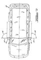
- Mirror assembly 10 is of the typical breakaway design and includes a housing 16 pivotably supported on an arm 18 extending outwardly from a generally triangularly shaped mounting plate 20. As shown in Figure 7, preferably two mirrors 10 will be mounted on a vehicle 14, one on each side thereof.
- Housing 16 may be of any desired shape and includes an upper wall portion 22, a lower wall portion 24, a forwardly facing wall portion 26 and inner and outer wall portions 28 and 30 all of which merge smoother together so as to present a pleasing appearance.
- the rearwardly facing portion of housing 16 is open and is adapted to receive a reflective mirror 32.
- Mirror 32 may be either of any suitable type such as flat, concave or convex or of the type which automatically adjusts to reduce glare.
- a suitably shaped support member (not shown) is secured within the housing and serves to movably support mirror within the opening.
- the support member may include suitable drive motors and the like for remote control adjustment of mirror as well as means for heating the mirror if desired.
- Housing 16 also contains a recessed portion 34 extending over at least a part of upper, inner, outer and forwardly facing portions 22, 28, 30 and 26 which is adapted to receive a decorative cover member 36 which cover member may be chromed, colored to match the vehicle or of some other finish to present an aesthetically pleasing appearance.
- mirror assembly 10 is typical of existing rear view mirror assemblies currently employed on various motor vehicles.
- mirror assembly 10 of the present invention also incorporates an auxiliary warning light assembly 38 integrated with the decorative cover member 36.
- auxiliary warning light assembly 38 includes a light housing comprising a base member 40 having an opening 42 therein which is adapted to receive a suitable electrical socket 44 having a light source 46 provided thereon.
- opening 42 will be designed with two or three radially outwardly and circumferentially extending open portions whereby segmented inner flange 48 of light socket 44 may be inserted and then turned a few degrees to lock it in place.
- any suitable available light source 46 may be utilized.
- a suitable pigtail and associated electrical connector 50 is also provided extending outwardly from socket 44 which is adapted to be connected to connector 52 of wiring harness 54 provided in housing 16.
- a lens member 56 is secured to base member 40 and is designed so as to direct light emitted from light source outwardly from mirror housing through an arc 58 extending approximately 90 degrees rearwardly from a line 60 passing through the mirror 10 and extending substantially perpendicular to the longitudinal axis 62 of the motor vehicle 14.
- the inner surface 64 of base member 40 will preferably be coated with a reflective material and shaped so as to direct a maximum amount of light from the light source 46 to the lens 56.
- Light assembly 38 will preferably be mechanically secured to decorative cover member 36 by means of integrally formed snap fasteners so as to form a one-piece assembly therewith.
- any other suitable manner of securing light assembly 38 to decorative cover member 36 may be used such as for example adhesive bonding, sonic welding, molding or even suitable separate fasteners.
- lens 38 have an outer surface which is shaped so as to form a substantially smooth continuation of the outer contour of decorative cover member as is shown in Figures 1 and 2.
- housing 16 is provided with an opening 66 on the recessed part of outer surface portion 30 which underlies decorative member 36. While housing 16 is shown as providing an opening 66 to accommodate light assembly 38, in some applications it may be desirable to provide an enclosed recess in place thereof. Additionally, as mentioned above, a wiring harness 54 having a suitable electrical connector 52 will be provided within housing 16 so as to be accessible through opening 66 or within the recess if such is provided in place of the opening 66.
- decorative member 36 In order to assemble decorative member 36 and associate light assembly 38, one need merely interconnect the two electrical connectors 50, 52 and thereafter assemble decorative member 36 to housing 16. As shown in Figure 4, decorative member 36 is provided with a plurality of spaced outwardly extending tangs 68 on the back surface 70 thereof. These tangs 70 are designed to be received within suitable openings provided in housing 16 and to cooperate with latch members provided therein to retain the decorative member 36 thereon in the same manner as in currently available mirror assemblies of this type.
- Warning light assembly 38 is intended to be interconnected with the vehicle turn signal system so that when one or the other of the turn signals are actuated, the light assembly 38 provided on the exterior mirror on the corresponding side of the vehicle will also be actuated. In this manner any other vehicle that may be approaching the vehicle equipped with the subject invention or that may be traveling in its blind spot will immediately be appraised of the equipped vehicle's intention to turn or change lanes even though they may not be in a position to see the vehicle tail lights. However, because the light is positioned on the outer wall portion 30 of the mirror assembly, the housing 16 and mirror 32 will prevent the driver of the vehicle from being distracted by this light when actuated.
- the subject invention is particularly well suited for offering of the auxiliary warning light as an optional accessory by vehicle manufacturers.
- the overall size and shape of the decorative member 36 incorporating the light assembly 38 is such that it may be easily and conveniently interchanged with a decorative member 72 which does not include the light assembly.
- the assembler need merely select one or the other of the two decorative cover members 36, 72 for attachment to the mirror housing 16 depending upon the desires of the intended customer. Further, should a purchaser of a vehicle decide at a later date to either add or delete the auxiliary lighting feature, it is only necessary to replace the decorative cover member 36 or 72 with the other cover member.
- FIG. 5 another embodiment of the subject invention is disclosed which further facilitates rapid and low cost assembly of the subject invention.
- base member 40, light socket 44 and connector 50 are replaced by a base member 73 and a light socket 74 having a pair of electrically conductive pins 76 extending outwardly therefrom.
- Mirror housing 16' is also modified by replacing opening 66 with a molded-in cavity 78 in which a pair of spaced openings 80 are provided positioned so as to receive pins 76 when decorative member 82 is assembled thereto.
- the assembler need not first interconnect the two electrical connectors 50, 52 but rather needs merely install the decorative cover member 82 during which pins 76 will be received within openings 80 thereby electrically connecting light assembly to the existing vehicle turn signal system.
- a cover member without the light assembly included is easily assembled to mirror housing 16 and will cover and conceal cavity 78 provided therein.
Abstract
Description
- The present invention relates generally to rear view mirror assemblies for motor vehicles and more particularly to exterior motor vehicle mirror assemblies which incorporate auxiliary warning lights.
- Auxiliary warning lights have long been incorporated on the sides of motor vehicles to provide a means of communicating the intentions of the operator thereof to adjacent vehicles such as for example the intention to change traffic lanes or to make a turn. Such lights are advantageous in providing notice to an adjacent vehicle that may be located in a blind spot and positioned such that the signalling vehicle's tail lights are not visible to the adjacent vehicle's operator.
- While incorporation of such auxiliary warning lights is relatively easy and straightforward on work-type vehicles it becomes a somewhat more complex problem when passenger-type vehicles are involved due in part to the importance of aesthetic appearance. Other considerations which may apply to any type of vehicle include the need to position the lights so as to minimize any impact on the vision of the vehicle operator and to maximize the area to the side and rear of the vehicle from which the auxiliary lighting is visible. Additionally, because in many cases the vehicle manufacturer may want to offer the auxiliary lighting arrangement as an option on certain vehicles, it is highly desirable that the lighting system be designed to easily and conveniently integrate with the existing vehicle design so as to minimize added labor and/or costs associated with its installation.
- The present invention provides a highly effective and aesthetically pleasing auxiliary lighting system which is integrated into the vehicle's exterior rear view mirror assembly. Preferably, the auxiliary warning light of the present invention will be positioned on the laterally outer surface of the vehicle's exterior rear view mirror in such a manner as to be visible throughout an arc extending about 90 degrees rearwardly from a line extending generally perpendicular to the longitudinal axis of the vehicle. In this manner maximum visibility of the auxiliary warning light is provided to vehicles coming alongside the equipped vehicle while still preventing the emitted light from being visible to the vehicle operator or oncoming traffic. It should be noted, however, that the auxiliary warning light may be positioned so as to be visible to oncoming traffic in addition to the above referenced arc should this be desired and may in fact replace fender side marker lights required in certain countries.
- In one form the light is integrated into a removable decorative covering which is secured to the mirror housing and a pigtail is provided for connecting the light to a wiring harness in the interior of the mirror housing. In a modification of this embodiment, the decorative cover member incorporating the light assembly is provided with a plug and the mirror housing includes a receptacle whereby electrical contacts on the cover member may be "plugged into" the receptacle as the decorative cover member is fitted to the housing. This last arrangement further reduces the costs associated with final assembly as no separate effort is required to make the electrical connections for the auxiliary warning light. Further, the integration of the light assembly into the decorative cover member greatly facilitates the offering of the auxiliary lighting feature as an option because only the decorative cover member need be changed to add or delete this auxiliary lighting feature.
- Additional advantages and features of the present invention will become apparent from the subsequent description and the appended claims taken in conjunction with the accompanying drawings.
-
- Figure 1 is a fragmentary perspective view of a side of a motor vehicle having an exterior rear view mirror assembly incorporating an auxiliary warning light provided thereon all in accordance with the present invention;
- Figure 2 is a side view of the mirror assembly of Figure 1;
- Figure 3 is a section view of the mirror light assembly of Figure 1, the section being taken along line 3-3 of Figure 1;
- Figure 4 is a perspective view of a mirror housing with alternative decorative cover members shown in position for installation thereon, all in accordance with the present invention;
- Figure 5 is a view of the back side of a decorative cover member having a light assembly incorporated therein which includes an integrally formed electrical connector in accordance with the present invention;
- Figure 6 is a view of a portion of a mirror housing incorporating an electrical outlet adapted to mate with the plug shown in Figure 5, all in accordance with the present invention; and
- Figure 7 is a plan view of a motor vehicle having mirrors in accordance with the present invention secured to opposite sides thereof.
-
- Referring now to the drawings and in particular to Figures 1 and 7, there is shown an exterior rear view mirror assembly indicated generally at 10 installed on the
door 12 of amotor vehicle 14.Mirror assembly 10 is of the typical breakaway design and includes a housing 16 pivotably supported on an arm 18 extending outwardly from a generally triangularlyshaped mounting plate 20. As shown in Figure 7, preferably twomirrors 10 will be mounted on avehicle 14, one on each side thereof. - Housing 16 may be of any desired shape and includes an
upper wall portion 22, alower wall portion 24, a forwardly facingwall portion 26 and inner andouter wall portions reflective mirror 32.Mirror 32 may be either of any suitable type such as flat, concave or convex or of the type which automatically adjusts to reduce glare. A suitably shaped support member (not shown) is secured within the housing and serves to movably support mirror within the opening. The support member may include suitable drive motors and the like for remote control adjustment of mirror as well as means for heating the mirror if desired. Housing 16 also contains arecessed portion 34 extending over at least a part of upper, inner, outer and forwardly facingportions decorative cover member 36 which cover member may be chromed, colored to match the vehicle or of some other finish to present an aesthetically pleasing appearance. - As thus far described,
mirror assembly 10 is typical of existing rear view mirror assemblies currently employed on various motor vehicles. However,mirror assembly 10 of the present invention also incorporates an auxiliarywarning light assembly 38 integrated with thedecorative cover member 36. - As best seen with reference to Figure 3, auxiliary
warning light assembly 38 includes a light housing comprising abase member 40 having anopening 42 therein which is adapted to receive a suitable electrical socket 44 having alight source 46 provided thereon. Preferably opening 42 will be designed with two or three radially outwardly and circumferentially extending open portions whereby segmentedinner flange 48 of light socket 44 may be inserted and then turned a few degrees to lock it in place. It should be noted that any suitableavailable light source 46 may be utilized. A suitable pigtail and associatedelectrical connector 50 is also provided extending outwardly from socket 44 which is adapted to be connected to connector 52 ofwiring harness 54 provided in housing 16. Alens member 56 is secured tobase member 40 and is designed so as to direct light emitted from light source outwardly from mirror housing through anarc 58 extending approximately 90 degrees rearwardly from aline 60 passing through themirror 10 and extending substantially perpendicular to the longitudinal axis 62 of themotor vehicle 14. In order to enhance the visible light transmitted by thelens 56 the inner surface 64 ofbase member 40 will preferably be coated with a reflective material and shaped so as to direct a maximum amount of light from thelight source 46 to thelens 56. -
Light assembly 38 will preferably be mechanically secured todecorative cover member 36 by means of integrally formed snap fasteners so as to form a one-piece assembly therewith. Although any other suitable manner of securinglight assembly 38 todecorative cover member 36 may be used such as for example adhesive bonding, sonic welding, molding or even suitable separate fasteners. It is desirable thatlens 38 have an outer surface which is shaped so as to form a substantially smooth continuation of the outer contour of decorative cover member as is shown in Figures 1 and 2. - In order to accommodate
light assembly 38, housing 16 is provided with an opening 66 on the recessed part ofouter surface portion 30 which underliesdecorative member 36. While housing 16 is shown as providing an opening 66 to accommodatelight assembly 38, in some applications it may be desirable to provide an enclosed recess in place thereof. Additionally, as mentioned above, awiring harness 54 having a suitable electrical connector 52 will be provided within housing 16 so as to be accessible through opening 66 or within the recess if such is provided in place of the opening 66. - In order to assemble
decorative member 36 andassociate light assembly 38, one need merely interconnect the twoelectrical connectors 50, 52 and thereafter assembledecorative member 36 to housing 16. As shown in Figure 4,decorative member 36 is provided with a plurality of spaced outwardly extendingtangs 68 on theback surface 70 thereof. Thesetangs 70 are designed to be received within suitable openings provided in housing 16 and to cooperate with latch members provided therein to retain thedecorative member 36 thereon in the same manner as in currently available mirror assemblies of this type. -
Warning light assembly 38 is intended to be interconnected with the vehicle turn signal system so that when one or the other of the turn signals are actuated, thelight assembly 38 provided on the exterior mirror on the corresponding side of the vehicle will also be actuated. In this manner any other vehicle that may be approaching the vehicle equipped with the subject invention or that may be traveling in its blind spot will immediately be appraised of the equipped vehicle's intention to turn or change lanes even though they may not be in a position to see the vehicle tail lights. However, because the light is positioned on theouter wall portion 30 of the mirror assembly, the housing 16 andmirror 32 will prevent the driver of the vehicle from being distracted by this light when actuated. - As previously mentioned, the subject invention is particularly well suited for offering of the auxiliary warning light as an optional accessory by vehicle manufacturers. As shown in Figure 4, the overall size and shape of the
decorative member 36 incorporating thelight assembly 38 is such that it may be easily and conveniently interchanged with a decorative member 72 which does not include the light assembly. Thus, during final assembly of the mirror, the assembler need merely select one or the other of the twodecorative cover members 36, 72 for attachment to the mirror housing 16 depending upon the desires of the intended customer. Further, should a purchaser of a vehicle decide at a later date to either add or delete the auxiliary lighting feature, it is only necessary to replace thedecorative cover member 36 or 72 with the other cover member. - Referring now to Figures 5 and 6, another embodiment of the subject invention is disclosed which further facilitates rapid and low cost assembly of the subject invention. In this embodiment,
base member 40, light socket 44 andconnector 50 are replaced by abase member 73 and alight socket 74 having a pair of electricallyconductive pins 76 extending outwardly therefrom. Mirror housing 16' is also modified by replacing opening 66 with a molded-incavity 78 in which a pair of spaced openings 80 are provided positioned so as to receivepins 76 when decorative member 82 is assembled thereto. Thus, with this embodiment the assembler need not first interconnect the twoelectrical connectors 50, 52 but rather needs merely install the decorative cover member 82 during whichpins 76 will be received within openings 80 thereby electrically connecting light assembly to the existing vehicle turn signal system. As with the previous embodiment, should a purchaser not desire to include the light assembly, a cover member without the light assembly included is easily assembled to mirror housing 16 and will cover andconceal cavity 78 provided therein. - While it will be apparent that the preferred embodiments of the invention disclosed are well calculated to provide the advantages and features above stated, it will be appreciated that the invention is susceptible to modification, variation and change without departing from the proper scope or fair meaning of the subjoined claims.
Claims (29)
- An exterior rear view mirror assembly comprising:a housing (16, 16') adapted to be secured to an outer surface of a motor vehicle and having a generally rearwardly facing opening; anda mirror (32) disposed within said opening; characterised in that said housing is constructed and arranged to have either of a first decorative cover member (36,82) and a second decorative cover member (72) secured in overlying relationship to an outer surface portion of said housing (16, 16'), said first cover member (36, 82) including a lighting feature (38, 46, 56) and said second cover member (72) not including a lighting feature (38, 46, 56).
- The assembly of claim 1, wherein said housing (16) is provided with openings to receive tangs (70) provided on said first and second cover members (36,72), said openings being provided with latch members to cooperate with said tangs to secure said first and second cover members to said housing in said overlying relationship.
- The assembly of claim 1 or claim 2, wherein said lighting feature is a light assembly (38).
- The assembly of any one of the preceding claims, wherein said lighting feature includes a light transmitting window (56).
- The assembly of claim 4, when dependent on claim 3, wherein said light assembly (38) has a light source (46) therein, said light source (46) being operable to provide a signal visible through said light transmitting window (56) to an adjacent motor vehicle when actuated.
- The assembly of claim 5, wherein said light assembly (38) includes a light housing (40, 73), said light source (46) including a light socket (44, 74) removably secured to said light housing (40, 73).
- The assembly of claim 5 or claim 6, wherein said housing includes an electrical connector (52, 80) adapted to establish an electrical connection to said light source (46).
- The assembly of claim 7, wherein said electrical connector (52, 80) is adapted to be electrically connected to said vehicle's turn signal system and to a mating connector (54, 76) associated with said light source (46) whereby said light source (46) may be actuated when said vehicle's turn signal is actuated.
- The assembly of claim 7 or claim 8, wherein said electrical connector (52) is accessible through an opening (66) in said housing (16) which is arranged to be covered by a said cover member (36, 72).
- The assembly of claim 8, wherein said housing (16') includes a cavity (78) adapted to receive said light source (46), said electrical connector (80) being located in said cavity (78).
- The assembly of claim 10, wherein said electrical connector comprises an electrical outlet (80) on a wall of said cavity (78).
- The assembly of any one of claims 5 to 11, wherein said light assembly (38) is mounted on said first cover member (36, 82).
- The assembly of claim 12, wherein said light assembly (38) is fixedly secured to said first cover member (36, 72, 82).
- The assembly of claim 6, or any one of claims 7 to 13 when dependent from claim 6, wherein said light transmitting window is a lens (56) and said light housing includes a light socket support member (40, 73) secured to said lens (56), said lens (56) having an outer surface contour forming a substantially smooth continuation of the outer surface of said first cover member (36, 72, 82).
- The assembly of claim 14, wherein said light socket support member (40, 73) includes a reflective inner surface (64) shaped to direct light emitted from said light source (46) to said lens (56).
- The assembly of claim 14 or claim 15, wherein said lens (56) is operative to direct light outwardly in a direction to be visible by other motor vehicles following and travelling alongside the motor vehicle.
- The assembly of claim 16, wherein said lens (56) is operative to direct light through an arc extending substantially 90° rearwardly from approximately a line passing through said mirror assembly and extending perpendicular to the longitudinal axis of the vehicle.
- The assembly of claim 8, or any one of claims 9 to 17 when dependent from claim 8, wherein said mating connector (76) is integrally formed with said light source.
- The assembly of claim 18, wherein said mating connector includes a pair of electrically conductive prongs (76) projecting outwardly of said light housing (73), said prongs (76) being connectable to said electrical connector (80) upon assembly of said first cover member (82) to said housing (16').
- The assembly of any one of the preceding claims,
wherein said housing (16) has an upper wall portion (22), a lower wall portion (24), a forwardly facing wall portion (26) and inner and outer wall portion (28, 30) co-operating to define a generally enclosed area leading from said rearwardly facing opening, and said cover members (36, 82) are arranged to be received within and substantially to cover a recessed portion (34) which extends over at least a part of said upper, forwardly facing and outer wall portions (22, 26, 30). - The assembly of any one of the preceding claims, wherein said mirror (32) is movably positioned within said rearwardly facing opening.
- The assembly of any one of the preceding claims, wherein the lighting feature is an auxiliary warning light.
- The assembly of any one of the preceding claims, further comprising said first cover member (36,82).
- The assembly of claim 23, wherein said first cover member (36, 82) is secured in overlying relationship to said outer surface portion of said housing (16, 16').
- A plurality of components for use in assembling an exterior rear view mirror assembly, the components comprising the mirror assembly of claim 23 or claim 24 and said second cover member (72).
- An exterior rear view mirror assembly comprising:a housing (16, 16') adapted to be secured to an outer surface of a motor vehicle and having a generally rearwardly facing opening; anda mirror (32) disposed within said opening; characterised in that said housing is constructed and arranged to have either of a first decorative cover member (36, 82) and a second decorative cover member (72) secured in overlying relationship to an outer surface portion of said housing (16, 16'), said first cover member (36, 82) including an auxiliary warning light (38, 46, 56) and said second cover member (72) not including an auxiliary warning light (38, 46, 56).
- An exterior rear view mirror assembly comprising:a housing (16, 16') adapted to be secured to an outer surface of a motor vehicle and having a generally rearwardly facing opening; anda mirror (32) disposed within said opening; characterised in that said housing is constructed and arranged to have either of a first decorative cover member (36, 82) and a second decorative cover member (72) secured in overlying relationship to an outer surface portion of said housing (16, 16'), said first cover member (36, 82) including a light assembly (38, 46, 56) and said second cover member (72) not including a light assembly (38, 46, 56).
- An exterior rear view mirror assembly comprising a housing (16, 16') adapted to be secured to an outer surface of a motor vehicle and having a generally rearwardly facing opening, a mirror (32) disposed within said opening, and a first decorative cover member (36, 82) secured in overlying relationship to an outer surface portion of said housing (16, 16'), characterised in that said decorative cover member (36, 82) includes a light transmitting window (56), a light assembly (38) having a light source (46) therein, said light source (46) being operable to provide a signal visible through said light transmitting window (56) to an adjacent motor vehicle when actuated.
- The assembly of claim 28, further incorporating at least one of the following additional features:
wherein said light assembly (38) includes a light housing (40, 73), said light source (46) including a light socket (44, 74) removably secured to said light housing (40, 73);
wherein said light assembly (38) is mounted on said decorative cover member (36, 82);
wherein said light assembly (38) is fixedly secured to said decorative cover member (36, 82);
wherein said light transmitting window is a lens (56) and said light housing includes a light socket support member (40, 73) secured to said lens (56), said lens (56) having an outer surface contour forming a substantially smooth continuation of the outer surface of said decorative member (36, 82);
wherein said light socket support member (40, 73) includes a reflective inner surface (64) shaped to direct light emitted from said light source (46) to said lens (56);
wherein said lens (56) is operative to direct light outwardly in a direction to be visible by other motor vehicles following and travelling alongside side motor vehicle;
wherein said lens (56) is operative to direct light through an arc extending substantially 90 DEG rearwardly from approximately a line passing through said mirror assembly and extending perpendicular to the longitudinal axis of said vehicle;
including an electrical connector (52, 80) adapted to establish an electrical connection to said supply source;
wherein said electrical connector (52, 80) is adapted to be electrically connected to said vehicle turn signal system, said light source (46) including a mating connector (54, 76) connected to said electrical connector whereby said light source (46) may be actuated when said vehicle turn signal is actuated;
wherein said electrical connector (52, 80) is accessible through an opening in said housing (16, 16') which is covered by said decorative cover member (36, 82) ;
wherein said housing (16') includes a cavity (78) adapted to receive said light source (46), said electrical connector (80) being located in said cavity (78) ;
wherein said electrical connector comprises an electrical outlet (80) on a wall of said cavity (78);
wherein said mating connector (76) is integrally formed with said light source;
wherein said mating connector includes a pair of electrically conductive prongs (76) projecting outwardly of said light housing (73), said prongs (76) being connectable to said electrical connector (80) upon assembly of said decorative cover member (82) to said housing (16');
wherein said housing (16) has an upper wall portion (22), a lower wall portion (24), a forwardly facing wall portion (26) and inner and outer wall portion (28, 30) co-operating to define a generally enclosed area leading from said rearwardly facing opening, and the decorative cover member (36, 82) is received within and substantially covers a recessed portion (34) which extends over at least a part of said upper, forwardly facing and outer wall portions (22, 26, 30);
wherein said mirror assembly includes a second decorative cover member (72), said second decorative cover member (72) being interchangeable with said first decorative cover member (36, 82) being secured to said housing (16, 16') when said light assembly (38) is not desired; and
wherein said mirror (32) is movably positioned within said rearwardly facing opening.
Applications Claiming Priority (3)
| Application Number | Priority Date | Filing Date | Title |
|---|---|---|---|
| US83786697A | 1997-04-25 | 1997-04-25 | |
| US837866 | 1997-04-25 | ||
| EP98302674A EP0873910B1 (en) | 1997-04-25 | 1998-04-06 | A plurality of components for use in assembing an exterior rear view mirror and method of assembly thereof |
Related Parent Applications (1)
| Application Number | Title | Priority Date | Filing Date |
|---|---|---|---|
| EP98302674A Division EP0873910B1 (en) | 1997-04-25 | 1998-04-06 | A plurality of components for use in assembing an exterior rear view mirror and method of assembly thereof |
Publications (2)
| Publication Number | Publication Date |
|---|---|
| EP1552984A2 true EP1552984A2 (en) | 2005-07-13 |
| EP1552984A3 EP1552984A3 (en) | 2006-05-10 |
Family
ID=25275655
Family Applications (2)
| Application Number | Title | Priority Date | Filing Date |
|---|---|---|---|
| EP98302674A Expired - Lifetime EP0873910B1 (en) | 1997-04-25 | 1998-04-06 | A plurality of components for use in assembing an exterior rear view mirror and method of assembly thereof |
| EP05008480A Withdrawn EP1552984A3 (en) | 1997-04-25 | 1998-04-06 | Exterior rear view mirror integral warning light |
Family Applications Before (1)
| Application Number | Title | Priority Date | Filing Date |
|---|---|---|---|
| EP98302674A Expired - Lifetime EP0873910B1 (en) | 1997-04-25 | 1998-04-06 | A plurality of components for use in assembing an exterior rear view mirror and method of assembly thereof |
Country Status (10)
| Country | Link |
|---|---|
| US (5) | US6250783B1 (en) |
| EP (2) | EP0873910B1 (en) |
| JP (2) | JPH10297362A (en) |
| KR (1) | KR19980081509A (en) |
| CN (1) | CN1197740A (en) |
| AU (1) | AU749050B2 (en) |
| BR (1) | BR9801451A (en) |
| CA (1) | CA2230930A1 (en) |
| DE (1) | DE69830685T2 (en) |
| ZA (1) | ZA983004B (en) |
Families Citing this family (110)
| Publication number | Priority date | Publication date | Assignee | Title |
|---|---|---|---|---|
| US6176602B1 (en) * | 1993-02-01 | 2001-01-23 | Donnelly Corporation | Vehicle exterior mirror system with signal light |
| US5497306A (en) | 1993-02-01 | 1996-03-05 | Donnelly Corporation | Exterior vehicle security light |
| US6276821B1 (en) * | 1992-12-16 | 2001-08-21 | Donnelly Corporation | Vehicle exterior mirror system with signal light |
| US5371659A (en) * | 1993-02-01 | 1994-12-06 | Donnelly Corporation | Remote-actuated exterior vehicle security light |
| US5823654A (en) | 1993-02-01 | 1998-10-20 | Donnelly Corporation | Universal exterior vehicle security light |
| US5910854A (en) | 1993-02-26 | 1999-06-08 | Donnelly Corporation | Electrochromic polymeric solid films, manufacturing electrochromic devices using such solid films, and processes for making such solid films and devices |
| US5668663A (en) | 1994-05-05 | 1997-09-16 | Donnelly Corporation | Electrochromic mirrors and devices |
| US20120020101A1 (en) | 1994-11-02 | 2012-01-26 | Magna Mirrors Of America, Inc. | Vehicle exterior mirror system |
| US9586526B2 (en) | 1995-04-21 | 2017-03-07 | Magna Mirrors Of America, Inc. | Vehicle exterior mirror system |
| US6891563B2 (en) | 1996-05-22 | 2005-05-10 | Donnelly Corporation | Vehicular vision system |
| CA2230930A1 (en) * | 1997-04-25 | 1998-10-25 | Dale Gathergood | Exterior rear view mirror integral warning light |
| US6172613B1 (en) | 1998-02-18 | 2001-01-09 | Donnelly Corporation | Rearview mirror assembly incorporating vehicle information display |
| US8294975B2 (en) | 1997-08-25 | 2012-10-23 | Donnelly Corporation | Automotive rearview mirror assembly |
| US6326613B1 (en) | 1998-01-07 | 2001-12-04 | Donnelly Corporation | Vehicle interior mirror assembly adapted for containing a rain sensor |
| US6124886A (en) | 1997-08-25 | 2000-09-26 | Donnelly Corporation | Modular rearview mirror assembly |
| US6690268B2 (en) | 2000-03-02 | 2004-02-10 | Donnelly Corporation | Video mirror systems incorporating an accessory module |
| US8288711B2 (en) | 1998-01-07 | 2012-10-16 | Donnelly Corporation | Interior rearview mirror system with forwardly-viewing camera and a control |
| US6445287B1 (en) | 2000-02-28 | 2002-09-03 | Donnelly Corporation | Tire inflation assistance monitoring system |
| US6477464B2 (en) | 2000-03-09 | 2002-11-05 | Donnelly Corporation | Complete mirror-based global-positioning system (GPS) navigation solution |
| US6329925B1 (en) | 1999-11-24 | 2001-12-11 | Donnelly Corporation | Rearview mirror assembly with added feature modular display |
| US6693517B2 (en) | 2000-04-21 | 2004-02-17 | Donnelly Corporation | Vehicle mirror assembly communicating wirelessly with vehicle accessories and occupants |
| GB9820622D0 (en) | 1998-09-23 | 1998-11-18 | Britax Geco Sa | Vehicle exterior mirror with antenna |
| US6264353B1 (en) | 1998-11-23 | 2001-07-24 | Lear Automotive Dearborn, Inc. | Exterior mirror with supplement turn signal |
| US8066415B2 (en) | 1999-06-17 | 2011-11-29 | Magna Mirrors Of America, Inc. | Exterior mirror vision system for a vehicle |
| US6894608B1 (en) * | 1999-07-22 | 2005-05-17 | Altra Technologies Incorporated | System and method for warning of potential collisions |
| GB2357269A (en) * | 1999-12-16 | 2001-06-20 | Bates Ind Co Ltd | Wing mirror with indicator light |
| DE20001407U1 (en) * | 2000-01-27 | 2000-03-16 | Reitter & Schefenacker Gmbh | Exterior rear view mirror for vehicles, preferably for motor vehicles |
| US6325517B1 (en) * | 2000-02-11 | 2001-12-04 | Su Chang Kuo | Rear vision mirror with cold light direction signal indicator |
| US6642839B1 (en) | 2000-02-16 | 2003-11-04 | Altra Technologies Incorporated | System and method of providing scalable sensor systems based on stand alone sensor modules |
| US7370983B2 (en) | 2000-03-02 | 2008-05-13 | Donnelly Corporation | Interior mirror assembly with display |
| US7167796B2 (en) | 2000-03-09 | 2007-01-23 | Donnelly Corporation | Vehicle navigation system for use with a telematics system |
| US7004593B2 (en) | 2002-06-06 | 2006-02-28 | Donnelly Corporation | Interior rearview mirror system with compass |
| DE60127151T2 (en) * | 2000-06-15 | 2007-11-08 | Schefenacker Vision Systems Usa Inc., Marysville | MIRROR WITH REPLACEABLE DECORATION CAP |
| ES2287266T3 (en) | 2001-01-23 | 2007-12-16 | Donnelly Corporation | IMPROVED VEHICLE LIGHTING SYSTEM. |
| US7255451B2 (en) | 2002-09-20 | 2007-08-14 | Donnelly Corporation | Electro-optic mirror cell |
| US7581859B2 (en) | 2005-09-14 | 2009-09-01 | Donnelly Corp. | Display device for exterior rearview mirror |
| US7216996B2 (en) * | 2001-06-15 | 2007-05-15 | Schefenacker Vision Systems Uk Ltd. | Mirror with interchangeable appearance covers |
| US6916100B2 (en) * | 2001-06-27 | 2005-07-12 | Donnelly Corporation | Vehicle exterior rearview mirror assembly |
| US6811288B2 (en) * | 2001-06-29 | 2004-11-02 | Donnelly Corporation | Sideview mirror assembly with utility features |
| US6962423B2 (en) * | 2001-11-06 | 2005-11-08 | Honeywell International Inc. | Multi-mode searchlight |
| US7091843B1 (en) * | 2002-11-05 | 2006-08-15 | Rajiv Singh Lal | Functional and ornamental vehicle accessories |
| EP1507681A4 (en) * | 2002-01-11 | 2011-01-26 | Rajiv S Lal | Functional and ornamental vehicle accessories |
| US6933837B2 (en) | 2002-01-25 | 2005-08-23 | Altra Technologies Incorporated | Trailer based collision warning system and method |
| US20030179087A1 (en) * | 2002-03-21 | 2003-09-25 | Stahel Alwin J | Mirror mounted turn signal light |
| US6926431B1 (en) | 2002-04-09 | 2005-08-09 | Magna Donnelly Mirrors North America, L.L.C. | Vehicular mirror assembly incorporating multifunctional illumination source |
| US7104676B2 (en) * | 2002-04-15 | 2006-09-12 | K.W. Muth Company, Inc. | Signaling assembly |
| WO2003091070A1 (en) * | 2002-04-24 | 2003-11-06 | Fico Mirrors, Sa | Outside rear-view mirror for motor vehicles |
| US6918674B2 (en) | 2002-05-03 | 2005-07-19 | Donnelly Corporation | Vehicle rearview mirror system |
| US7329013B2 (en) | 2002-06-06 | 2008-02-12 | Donnelly Corporation | Interior rearview mirror system with compass |
| DE10238264B4 (en) * | 2002-08-21 | 2006-03-02 | Mayr Tuning Gmbh | Indicator lights for vehicle side mirrors |
| DE10336615A1 (en) * | 2002-08-21 | 2005-03-03 | Mayr Tuning Gmbh | Light-body insert for subsequent installation in standard vehicle side mirrors |
| WO2004103772A2 (en) | 2003-05-19 | 2004-12-02 | Donnelly Corporation | Mirror assembly for vehicle |
| US7310177B2 (en) | 2002-09-20 | 2007-12-18 | Donnelly Corporation | Electro-optic reflective element assembly |
| EP1543358A2 (en) | 2002-09-20 | 2005-06-22 | Donnelly Corporation | Mirror reflective element assembly |
| US6924943B2 (en) * | 2002-12-02 | 2005-08-02 | Light Prescriptions Innovators, Llc | Asymmetric TIR lenses producing off-axis beams |
| USD535984S1 (en) | 2003-01-06 | 2007-01-30 | Rajiv S. Lal | Ring-shaped vehicle accessory |
| JP4110989B2 (en) | 2003-02-03 | 2008-07-02 | 市光工業株式会社 | Outside mirror device with lamp |
| JP4262502B2 (en) * | 2003-03-25 | 2009-05-13 | 株式会社ミツバ | Door mirror with side blinker |
| US6986596B2 (en) * | 2003-09-02 | 2006-01-17 | Trw Automotive U.S. Llc | Exterior rearview mirror assembly |
| US7446924B2 (en) | 2003-10-02 | 2008-11-04 | Donnelly Corporation | Mirror reflective element assembly including electronic component |
| US7308341B2 (en) | 2003-10-14 | 2007-12-11 | Donnelly Corporation | Vehicle communication system |
| US6932497B1 (en) * | 2003-12-17 | 2005-08-23 | Jean-San Huang | Signal light and rear-view mirror arrangement |
| JP4321346B2 (en) * | 2004-05-10 | 2009-08-26 | 市光工業株式会社 | Outside mirror device for vehicle |
| DE102004045299B4 (en) * | 2004-09-16 | 2006-07-27 | Daimlerchrysler Ag | Exterior rearview mirror for a motor vehicle |
| EP1883855B1 (en) | 2005-05-16 | 2011-07-20 | Donnelly Corporation | Vehicle mirror assembly with indicia at reflective element |
| US20070091479A1 (en) * | 2005-10-19 | 2007-04-26 | Marcus Penny | Combination mirror and turn signal for vehicles |
| EP1949666B1 (en) | 2005-11-01 | 2013-07-17 | Magna Mirrors of America, Inc. | Interior rearview mirror with display |
| JP4569444B2 (en) * | 2005-11-09 | 2010-10-27 | 市光工業株式会社 | Outside mirror device for vehicle |
| DE102006025070A1 (en) * | 2006-05-23 | 2007-11-29 | Schefenacker Vision Systems Germany Gmbh | Exterior mirrors of a vehicle |
| JP4921916B2 (en) | 2006-10-13 | 2012-04-25 | 株式会社村上開明堂 | door mirror |
| US20080218871A1 (en) * | 2007-03-05 | 2008-09-11 | K.W. Muth Company, Inc. | Mirror assembly |
| JP5115053B2 (en) * | 2007-06-25 | 2013-01-09 | 市光工業株式会社 | Vehicle side mirror |
| GB2450710B (en) * | 2007-07-04 | 2012-01-11 | Land Rover Uk Ltd | Vision assistance modules for vehicles |
| US8154418B2 (en) | 2008-03-31 | 2012-04-10 | Magna Mirrors Of America, Inc. | Interior rearview mirror system |
| US9487144B2 (en) | 2008-10-16 | 2016-11-08 | Magna Mirrors Of America, Inc. | Interior mirror assembly with display |
| DE102008059147A1 (en) * | 2008-11-26 | 2010-06-10 | Audi Ag | Motor vehicle with hybrid drive and external display device for indicating a current mode of operation of the hybrid drive |
| US10279684B2 (en) * | 2008-12-08 | 2019-05-07 | Ford Global Technologies, Llc | System and method for controlling heating in a hybrid vehicle using a power source external to the hybrid vehicle |
| US20100140244A1 (en) * | 2008-12-08 | 2010-06-10 | Ford Global Technologies, Llc | Integrated side view mirror assembly and electrical port for an automotive vehicle |
| JP2011084184A (en) * | 2009-10-16 | 2011-04-28 | Mitsuba Corp | Door mirror for vehicle |
| ATE539916T1 (en) * | 2009-11-26 | 2012-01-15 | Smr Patents Sarl | REARVIEW MIRROR UNIT WITH ELECTRICAL SUB UNIT |
| JP5501799B2 (en) * | 2010-02-25 | 2014-05-28 | 株式会社村上開明堂 | Vehicle door mirror |
| JP5411021B2 (en) * | 2010-02-25 | 2014-02-12 | 株式会社村上開明堂 | Door mirror housing structure |
| DE102011113184B4 (en) | 2010-09-28 | 2020-06-10 | Magna Mirrors Holding Gmbh | Rear-view mirror housing unit for a vehicle exterior mirror |
| JP2012214204A (en) * | 2011-03-31 | 2012-11-08 | Ichikoh Ind Ltd | Outside mirror device for vehicle |
| USD660209S1 (en) | 2011-05-17 | 2012-05-22 | Code 3, Inc. | Light module for a side mounted rear view mirror of vehicle |
| US9004373B2 (en) | 2012-07-03 | 2015-04-14 | Honda Motor Co., Ltd. | Ultrasonic welded headlight washer assemblies |
| US9150208B2 (en) * | 2012-12-18 | 2015-10-06 | Caterpillar Global Mining Llc | Park brake logic |
| CA2903843C (en) | 2013-03-15 | 2019-03-05 | Alfred E. Mann Foundation For Scientific Research | Current sensing multiple output current stimulators with fast turn on time |
| EP3000660B1 (en) * | 2013-07-04 | 2018-03-28 | Honda Motor Co., Ltd. | Door mirror device for vehicle |
| WO2015017475A2 (en) | 2013-07-29 | 2015-02-05 | Alfred E. Mann Foundation For Scientific Research | Microprocessor controlled class e driver |
| WO2016025915A1 (en) | 2014-08-15 | 2016-02-18 | Axonics Modulation Technologies, Inc. | Integrated electromyographic clinician programmer for use with an implantable neurostimulator |
| US9700731B2 (en) | 2014-08-15 | 2017-07-11 | Axonics Modulation Technologies, Inc. | Antenna and methods of use for an implantable nerve stimulator |
| ES2705711T3 (en) | 2014-08-15 | 2019-03-26 | Axonics Modulation Tech Inc | Positioning of electromyographic derivation and titration of stimulation in a nervous stimulation system for the treatment of overactive bladder |
| WO2016025912A1 (en) | 2014-08-15 | 2016-02-18 | Axonics Modulation Technologies, Inc. | Systems and methods for neurostimulation electrode configurations based on neural localization |
| CA2982572C (en) | 2014-08-15 | 2022-10-11 | Axonics Modulation Technologies, Inc. | Implantable lead affixation structure for nerve stimulation to alleviate bladder dysfunction and other indications |
| AU2015301489B2 (en) | 2014-08-15 | 2020-01-23 | Axonics Modulation Technologies, Inc. | External pulse generator device and associated methods for trial nerve stimulation |
| CN107427685B (en) | 2015-01-09 | 2021-09-21 | 艾克索尼克斯股份有限公司 | Attachment devices for use with neurostimulation charging devices and associated methods |
| EP3242712B1 (en) | 2015-01-09 | 2019-04-10 | Axonics Modulation Technologies, Inc. | Patient remote and associated methods of use with a nerve stimulation system |
| CA2991903C (en) | 2015-07-10 | 2023-10-17 | Axonics Modulation Technologies, Inc. | Implantable nerve stimulator having internal electronics without asic and methods of use |
| JP6876363B2 (en) | 2016-01-29 | 2021-05-26 | アクソニクス モジュレーション テクノロジーズ インコーポレイテッド | Methods and systems for frequency adjustment that optimize the charging of implantable neurostimulators |
| CA3014195A1 (en) | 2016-02-12 | 2017-08-17 | Axonics Modulation Technologies, Inc. | External pulse generator device and associated methods for trial nerve stimulation |
| KR200481741Y1 (en) * | 2016-02-22 | 2016-11-04 | 강진범 | lighting device irradiating the light on the road surface linked turn signal lamp of a vehicle for forming LED reflections in specific notifying area |
| US10953788B2 (en) | 2016-05-21 | 2021-03-23 | JST Performance, LLC | Method and apparatus for vehicular light fixtures |
| WO2019165108A1 (en) | 2018-02-22 | 2019-08-29 | Axonics Modulation Technologies, Inc. | Neurostimulation leads for trial nerve stimulation and methods of use |
| US11642537B2 (en) | 2019-03-11 | 2023-05-09 | Axonics, Inc. | Charging device with off-center coil |
| DE102019203572A1 (en) * | 2019-03-15 | 2020-09-17 | Hs-Schoch Gmbh | Vehicle attachment with optional lighting device |
| US11383645B2 (en) | 2019-05-13 | 2022-07-12 | Magna Mirrors Of America, Inc. | Exterior rearview mirror with power extending mechanism |
| WO2020242900A1 (en) | 2019-05-24 | 2020-12-03 | Axonics Modulation Technologies, Inc. | Trainer device for a neurostimulator programmer and associated methods of use with a neurostimulation system |
| US11439829B2 (en) | 2019-05-24 | 2022-09-13 | Axonics, Inc. | Clinician programmer methods and systems for maintaining target operating temperatures |
| US11525558B2 (en) * | 2020-10-14 | 2022-12-13 | Hunter Industries, Inc. | Outdoor landscape light |
Family Cites Families (39)
| Publication number | Priority date | Publication date | Assignee | Title |
|---|---|---|---|---|
| US1458703A (en) | 1921-03-14 | 1923-06-12 | Ray G Rogers | Combined signal, spotlight, and mirror |
| US1602094A (en) | 1922-10-28 | 1926-10-05 | John H Bolton | Combined vehicle signal, spotlight, and mirror |
| US1563258A (en) | 1924-04-10 | 1925-11-24 | John A Cunningham | Automobile signal |
| US2010138A (en) | 1931-11-12 | 1935-08-06 | Autoposts Company Inc | Lighting, signaling, and indicating accessory for motor vehicles |
| US2457348A (en) | 1946-03-07 | 1948-12-28 | Loyal E Harris | Combined signal light and rearview mirror |
| DE1680817B1 (en) | 1966-03-18 | 1970-10-22 | Yorck Talbot | Two-part streamlined exterior rearview mirror for motor vehicles |
| DE1961064A1 (en) | 1969-12-05 | 1971-06-16 | Dragoco Gerberding Co Gmbh | Process for the production of plant extract concentrates which cannot be broken down by fermentation |
| US5109214A (en) | 1980-04-14 | 1992-04-28 | Heidman Jr William A | Vehicle directional signal switch with lane changing position interconnecting to flashing lamps on left and right side rear view mirrors and flashing brake lamps in reverse |
| US4475100A (en) | 1982-02-22 | 1984-10-02 | Duh Ching Jeng | Side mirror with indicator light |
| JPS58188733A (en) * | 1982-04-28 | 1983-11-04 | Teruaki Yoshida | Direction indicator device for back mirror |
| GB8401920D0 (en) | 1984-01-25 | 1984-02-29 | Winstanley J | Rear view mirror |
| JPS60161646A (en) | 1984-02-01 | 1985-08-23 | Hitachi Ltd | Lead frame for semiconductor device |
| JPS60139551U (en) * | 1984-02-28 | 1985-09-14 | 株式会社東海理化電機製作所 | Door mirror device with lighting |
| GB8417232D0 (en) * | 1984-07-06 | 1984-08-08 | Cooke M J | Combination mirror |
| US4583155A (en) | 1984-09-04 | 1986-04-15 | Hart Robert L | Side mounted rear view mirror with brake light |
| JPS61166745A (en) | 1985-01-21 | 1986-07-28 | Yamazaki Jutaku Kanri:Kk | Flasher lamp of automobile |
| JPH0735760B2 (en) | 1986-11-25 | 1995-04-19 | 株式会社クボタ | Accumulation fuel injection device for diesel engine |
| KR910002276B1 (en) | 1987-07-24 | 1991-04-11 | 기요시 야마다 | Rear-view mirror with light at car side |
| WO1989001425A1 (en) | 1987-08-07 | 1989-02-23 | Robert Nash Peel | Motor vehicle turn indicators |
| US4916430A (en) | 1988-11-03 | 1990-04-10 | Vu Thuan D | Back up rear view mirror light |
| JPH0323824A (en) * | 1989-06-20 | 1991-01-31 | Sanyo Electric Co Ltd | Vacuum cleaner |
| US5059015A (en) | 1990-07-20 | 1991-10-22 | Tran Donald Q | Vehicular signal mirror apparatus |
| DE9101029U1 (en) * | 1991-01-30 | 1991-04-18 | Gou, Neng-Shyan, Baan-Chyau City, Tw | |
| JP2570483Y2 (en) | 1991-06-13 | 1998-05-06 | 忠男 田代 | Automotive turn signal device |
| DE4141208A1 (en) | 1991-12-13 | 1993-06-17 | Sakae Urushizaki | Motor vehicle road safety device using auxiliary direction indicators - has intermittently operated light source combined with each wing rear view mirror controlled by direction indicator lever |
| US5313335A (en) | 1992-06-05 | 1994-05-17 | Delco Electronics Corporation | Blindzone signal indicator |
| US5371659A (en) | 1993-02-01 | 1994-12-06 | Donnelly Corporation | Remote-actuated exterior vehicle security light |
| US5497306A (en) | 1993-02-01 | 1996-03-05 | Donnelly Corporation | Exterior vehicle security light |
| US5303130A (en) * | 1992-12-28 | 1994-04-12 | Wei Yung Feng | Illuminating automobile sideview mirror |
| DE9409566U1 (en) * | 1994-06-14 | 1994-08-04 | Wei Yung Feng | Illuminated car side mirror |
| US6019475A (en) | 1994-09-30 | 2000-02-01 | Donnelly Corporation | Modular rearview mirror assembly including an electronic control module |
| JPH08142745A (en) * | 1994-11-17 | 1996-06-04 | Kyowa Shatai:Kk | Auxiliary flasher lamp for automobile |
| US5499169A (en) * | 1995-05-16 | 1996-03-12 | Chen; Chun-Ming | Rearview mirror lamp circuit assembly |
| JPH0995177A (en) * | 1995-09-30 | 1997-04-08 | Yamasa Nousan Kk | Side mirror fitted with lighting device |
| US5660457A (en) | 1995-11-07 | 1997-08-26 | Whelen Engineering Company, Inc. | Integrated warning light and rear-view mirror |
| DE19616064A1 (en) * | 1996-04-23 | 1996-12-19 | Feldmeier Klaus Ulrich | Vehicle outline indicating lights |
| ES2139486B1 (en) * | 1996-07-24 | 2000-08-16 | Barros Garcia Alex Rodrigo | EXTREME FRAME WITH MULTIDIRECTIONAL SIGNAL FOR VEHICLES OF 2, 4 OR MORE WHEELS. |
| CA2230930A1 (en) * | 1997-04-25 | 1998-10-25 | Dale Gathergood | Exterior rear view mirror integral warning light |
| US6254262B1 (en) * | 1998-11-27 | 2001-07-03 | Crunk Paul D | Signaling lamp having led light array with removable plastic lens |
-
1998
- 1998-03-03 CA CA002230930A patent/CA2230930A1/en not_active Abandoned
- 1998-03-27 JP JP10100566A patent/JPH10297362A/en active Pending
- 1998-04-06 DE DE69830685T patent/DE69830685T2/en not_active Expired - Lifetime
- 1998-04-06 EP EP98302674A patent/EP0873910B1/en not_active Expired - Lifetime
- 1998-04-06 EP EP05008480A patent/EP1552984A3/en not_active Withdrawn
- 1998-04-08 ZA ZA983004A patent/ZA983004B/en unknown
- 1998-04-17 KR KR1019980013771A patent/KR19980081509A/en active Search and Examination
- 1998-04-20 AU AU61976/98A patent/AU749050B2/en not_active Ceased
- 1998-04-24 CN CN98107337A patent/CN1197740A/en active Pending
- 1998-04-24 BR BR9801451-0A patent/BR9801451A/en not_active Application Discontinuation
-
1999
- 1999-07-12 US US09/351,249 patent/US6250783B1/en not_active Expired - Lifetime
-
2001
- 2001-05-02 US US09/847,610 patent/US6517227B2/en not_active Expired - Lifetime
-
2002
- 2002-05-14 US US10/145,208 patent/US6644838B2/en not_active Expired - Lifetime
-
2003
- 2003-08-20 US US10/644,682 patent/US6905235B2/en not_active Expired - Lifetime
-
2004
- 2004-02-23 JP JP2004045999A patent/JP4212490B2/en not_active Expired - Fee Related
-
2005
- 2005-05-06 US US11/123,537 patent/US7108410B2/en not_active Expired - Lifetime
Non-Patent Citations (1)
| Title |
|---|
| None |
Also Published As
| Publication number | Publication date |
|---|---|
| EP0873910A2 (en) | 1998-10-28 |
| CN1197740A (en) | 1998-11-04 |
| US20040004842A1 (en) | 2004-01-08 |
| ZA983004B (en) | 1998-10-21 |
| JP4212490B2 (en) | 2009-01-21 |
| DE69830685T2 (en) | 2006-05-04 |
| DE69830685D1 (en) | 2005-08-04 |
| US6905235B2 (en) | 2005-06-14 |
| US6250783B1 (en) | 2001-06-26 |
| AU6197698A (en) | 1998-10-29 |
| BR9801451A (en) | 1999-12-07 |
| US6517227B2 (en) | 2003-02-11 |
| JP2004196298A (en) | 2004-07-15 |
| AU749050B2 (en) | 2002-06-20 |
| US7108410B2 (en) | 2006-09-19 |
| JPH10297362A (en) | 1998-11-10 |
| US6644838B2 (en) | 2003-11-11 |
| CA2230930A1 (en) | 1998-10-25 |
| KR19980081509A (en) | 1998-11-25 |
| EP1552984A3 (en) | 2006-05-10 |
| US20010026455A1 (en) | 2001-10-04 |
| EP0873910B1 (en) | 2005-06-29 |
| EP0873910A3 (en) | 1999-05-06 |
| US20020141199A1 (en) | 2002-10-03 |
| US20050195616A1 (en) | 2005-09-08 |
Similar Documents
| Publication | Publication Date | Title |
|---|---|---|
| US6517227B2 (en) | Exterior rear view mirror integral warning light | |
| US5823654A (en) | Universal exterior vehicle security light | |
| US5497306A (en) | Exterior vehicle security light | |
| JP2004196298A5 (en) | ||
| EP1433659B1 (en) | Outer mirror assembly | |
| US6986596B2 (en) | Exterior rearview mirror assembly | |
| US7008089B1 (en) | Exterior rear view mirror having a chin strap and a repeater | |
| MXPA98002772A (en) | Integral warning lamp with external mirror mirror | |
| EP1232072B1 (en) | Vehicle side mirror assembly with integral illumination and signal lighting | |
| WO2001028814A2 (en) | Interchangeable mirror scalp for trailer towing |
Legal Events
| Date | Code | Title | Description |
|---|---|---|---|
| PUAI | Public reference made under article 153(3) epc to a published international application that has entered the european phase |
Free format text: ORIGINAL CODE: 0009012 |
|
| AC | Divisional application: reference to earlier application |
Ref document number: 0873910 Country of ref document: EP Kind code of ref document: P |
|
| AK | Designated contracting states |
Kind code of ref document: A2 Designated state(s): DE ES FR GB IT SE |
|
| PUAL | Search report despatched |
Free format text: ORIGINAL CODE: 0009013 |
|
| AK | Designated contracting states |
Kind code of ref document: A3 Designated state(s): DE ES FR GB IT SE |
|
| 17P | Request for examination filed |
Effective date: 20060616 |
|
| AKX | Designation fees paid |
Designated state(s): DE ES FR GB IT SE |
|
| 111Z | Information provided on other rights and legal means of execution |
Free format text: DE ES FR GB IT SE Effective date: 20080627 |
|
| RAP1 | Party data changed (applicant data changed or rights of an application transferred) |
Owner name: VISIOCORP PATENTS S.A.R.L. |
|
| RAP1 | Party data changed (applicant data changed or rights of an application transferred) |
Owner name: VISIOCORP PATENTS S.A.R.L. |
|
| 17Q | First examination report despatched |
Effective date: 20081112 |
|
| RAP1 | Party data changed (applicant data changed or rights of an application transferred) |
Owner name: SMR PATENTS S.A.R.L. |
|
| STAA | Information on the status of an ep patent application or granted ep patent |
Free format text: STATUS: THE APPLICATION HAS BEEN WITHDRAWN |
|
| 18W | Application withdrawn |
Effective date: 20120418 |
|
| D11X | Information provided on other rights and legal means of execution (deleted) |