EP1540077B1 - Measuring arrangement in a shortened dry end of a tissue machine - Google Patents
Measuring arrangement in a shortened dry end of a tissue machine Download PDFInfo
- Publication number
- EP1540077B1 EP1540077B1 EP03784716A EP03784716A EP1540077B1 EP 1540077 B1 EP1540077 B1 EP 1540077B1 EP 03784716 A EP03784716 A EP 03784716A EP 03784716 A EP03784716 A EP 03784716A EP 1540077 B1 EP1540077 B1 EP 1540077B1
- Authority
- EP
- European Patent Office
- Prior art keywords
- web
- dryer
- support
- measuring
- paper
- Prior art date
- Legal status (The legal status is an assumption and is not a legal conclusion. Google has not performed a legal analysis and makes no representation as to the accuracy of the status listed.)
- Expired - Lifetime
Links
- 239000004744 fabric Substances 0.000 claims description 32
- 239000000835 fiber Substances 0.000 claims description 24
- 238000000034 method Methods 0.000 claims description 18
- 239000013307 optical fiber Substances 0.000 claims description 13
- 238000001035 drying Methods 0.000 claims description 7
- 238000007605 air drying Methods 0.000 claims description 4
- 238000004804 winding Methods 0.000 claims description 3
- 230000000087 stabilizing effect Effects 0.000 abstract description 2
- 238000005070 sampling Methods 0.000 description 12
- 238000005259 measurement Methods 0.000 description 7
- 238000011144 upstream manufacturing Methods 0.000 description 7
- 230000003287 optical effect Effects 0.000 description 6
- 230000002285 radioactive effect Effects 0.000 description 5
- 230000008901 benefit Effects 0.000 description 4
- 239000011888 foil Substances 0.000 description 4
- 238000001914 filtration Methods 0.000 description 3
- 238000000691 measurement method Methods 0.000 description 3
- 230000005540 biological transmission Effects 0.000 description 2
- 239000000428 dust Substances 0.000 description 2
- 238000012986 modification Methods 0.000 description 2
- 230000004048 modification Effects 0.000 description 2
- 238000012544 monitoring process Methods 0.000 description 2
- 238000001228 spectrum Methods 0.000 description 2
- 238000010183 spectrum analysis Methods 0.000 description 2
- 238000012546 transfer Methods 0.000 description 2
- 238000012935 Averaging Methods 0.000 description 1
- 238000010521 absorption reaction Methods 0.000 description 1
- 238000009825 accumulation Methods 0.000 description 1
- 239000007900 aqueous suspension Substances 0.000 description 1
- 238000007664 blowing Methods 0.000 description 1
- 238000004140 cleaning Methods 0.000 description 1
- 230000002596 correlated effect Effects 0.000 description 1
- 238000010168 coupling process Methods 0.000 description 1
- 238000005859 coupling reaction Methods 0.000 description 1
- 238000001514 detection method Methods 0.000 description 1
- 230000000694 effects Effects 0.000 description 1
- 239000011521 glass Substances 0.000 description 1
- 231100001261 hazardous Toxicity 0.000 description 1
- 238000012423 maintenance Methods 0.000 description 1
- 238000004519 manufacturing process Methods 0.000 description 1
- 230000005855 radiation Effects 0.000 description 1
- 238000000926 separation method Methods 0.000 description 1
- 230000003595 spectral effect Effects 0.000 description 1
Images


Classifications
-
- G—PHYSICS
- G01—MEASURING; TESTING
- G01N—INVESTIGATING OR ANALYSING MATERIALS BY DETERMINING THEIR CHEMICAL OR PHYSICAL PROPERTIES
- G01N33/00—Investigating or analysing materials by specific methods not covered by groups G01N1/00 - G01N31/00
- G01N33/34—Paper
- G01N33/346—Paper paper sheets
-
- B—PERFORMING OPERATIONS; TRANSPORTING
- B65—CONVEYING; PACKING; STORING; HANDLING THIN OR FILAMENTARY MATERIAL
- B65H—HANDLING THIN OR FILAMENTARY MATERIAL, e.g. SHEETS, WEBS, CABLES
- B65H18/00—Winding webs
- B65H18/02—Supporting web roll
-
- B—PERFORMING OPERATIONS; TRANSPORTING
- B65—CONVEYING; PACKING; STORING; HANDLING THIN OR FILAMENTARY MATERIAL
- B65H—HANDLING THIN OR FILAMENTARY MATERIAL, e.g. SHEETS, WEBS, CABLES
- B65H18/00—Winding webs
- B65H18/08—Web-winding mechanisms
- B65H18/26—Mechanisms for controlling contact pressure on winding-web package, e.g. for regulating the quantity of air between web layers
-
- B—PERFORMING OPERATIONS; TRANSPORTING
- B65—CONVEYING; PACKING; STORING; HANDLING THIN OR FILAMENTARY MATERIAL
- B65H—HANDLING THIN OR FILAMENTARY MATERIAL, e.g. SHEETS, WEBS, CABLES
- B65H23/00—Registering, tensioning, smoothing or guiding webs
- B65H23/04—Registering, tensioning, smoothing or guiding webs longitudinally
- B65H23/24—Registering, tensioning, smoothing or guiding webs longitudinally by fluid action, e.g. to retard the running web
-
- D—TEXTILES; PAPER
- D21—PAPER-MAKING; PRODUCTION OF CELLULOSE
- D21F—PAPER-MAKING MACHINES; METHODS OF PRODUCING PAPER THEREON
- D21F11/00—Processes for making continuous lengths of paper, or of cardboard, or of wet web for fibre board production, on paper-making machines
- D21F11/14—Making cellulose wadding, filter or blotting paper
- D21F11/145—Making cellulose wadding, filter or blotting paper including a through-drying process
-
- D—TEXTILES; PAPER
- D21—PAPER-MAKING; PRODUCTION OF CELLULOSE
- D21F—PAPER-MAKING MACHINES; METHODS OF PRODUCING PAPER THEREON
- D21F3/00—Press section of machines for making continuous webs of paper
-
- D—TEXTILES; PAPER
- D21—PAPER-MAKING; PRODUCTION OF CELLULOSE
- D21F—PAPER-MAKING MACHINES; METHODS OF PRODUCING PAPER THEREON
- D21F5/00—Dryer section of machines for making continuous webs of paper
-
- D—TEXTILES; PAPER
- D21—PAPER-MAKING; PRODUCTION OF CELLULOSE
- D21G—CALENDERS; ACCESSORIES FOR PAPER-MAKING MACHINES
- D21G9/00—Other accessories for paper-making machines
- D21G9/0009—Paper-making control systems
- D21G9/0036—Paper-making control systems controlling the press or drying section
-
- D—TEXTILES; PAPER
- D21—PAPER-MAKING; PRODUCTION OF CELLULOSE
- D21G—CALENDERS; ACCESSORIES FOR PAPER-MAKING MACHINES
- D21G9/00—Other accessories for paper-making machines
- D21G9/0063—Devices for threading a web tail through a paper-making machine
-
- B—PERFORMING OPERATIONS; TRANSPORTING
- B65—CONVEYING; PACKING; STORING; HANDLING THIN OR FILAMENTARY MATERIAL
- B65H—HANDLING THIN OR FILAMENTARY MATERIAL, e.g. SHEETS, WEBS, CABLES
- B65H2301/00—Handling processes for sheets or webs
- B65H2301/40—Type of handling process
- B65H2301/41—Winding, unwinding
- B65H2301/413—Supporting web roll
- B65H2301/4137—Supporting web roll on its outer circumference
- B65H2301/41372—Supporting web roll on its outer circumference rollers or balls arrangement
- B65H2301/41376—Supporting web roll on its outer circumference rollers or balls arrangement arranged in a non-stationary manner, i.e. changing according to actual roll diameter
-
- B—PERFORMING OPERATIONS; TRANSPORTING
- B65—CONVEYING; PACKING; STORING; HANDLING THIN OR FILAMENTARY MATERIAL
- B65H—HANDLING THIN OR FILAMENTARY MATERIAL, e.g. SHEETS, WEBS, CABLES
- B65H2401/00—Materials used for the handling apparatus or parts thereof; Properties thereof
- B65H2401/10—Materials
- B65H2401/11—Polymer compositions
- B65H2401/112—Fibre reinforced
-
- B—PERFORMING OPERATIONS; TRANSPORTING
- B65—CONVEYING; PACKING; STORING; HANDLING THIN OR FILAMENTARY MATERIAL
- B65H—HANDLING THIN OR FILAMENTARY MATERIAL, e.g. SHEETS, WEBS, CABLES
- B65H2406/00—Means using fluid
- B65H2406/10—Means using fluid made only for exhausting gaseous medium
- B65H2406/11—Means using fluid made only for exhausting gaseous medium producing fluidised bed
- B65H2406/112—Means using fluid made only for exhausting gaseous medium producing fluidised bed for handling material along preferably rectilinear path, e.g. nozzle bed for web
-
- B—PERFORMING OPERATIONS; TRANSPORTING
- B65—CONVEYING; PACKING; STORING; HANDLING THIN OR FILAMENTARY MATERIAL
- B65H—HANDLING THIN OR FILAMENTARY MATERIAL, e.g. SHEETS, WEBS, CABLES
- B65H2515/00—Physical entities not provided for in groups B65H2511/00 or B65H2513/00
- B65H2515/10—Mass, e.g. mass flow rate; Weight; Inertia
-
- B—PERFORMING OPERATIONS; TRANSPORTING
- B65—CONVEYING; PACKING; STORING; HANDLING THIN OR FILAMENTARY MATERIAL
- B65H—HANDLING THIN OR FILAMENTARY MATERIAL, e.g. SHEETS, WEBS, CABLES
- B65H2515/00—Physical entities not provided for in groups B65H2511/00 or B65H2513/00
- B65H2515/805—Humidity
-
- B—PERFORMING OPERATIONS; TRANSPORTING
- B65—CONVEYING; PACKING; STORING; HANDLING THIN OR FILAMENTARY MATERIAL
- B65H—HANDLING THIN OR FILAMENTARY MATERIAL, e.g. SHEETS, WEBS, CABLES
- B65H2553/00—Sensing or detecting means
- B65H2553/80—Arangement of the sensing means
- B65H2553/82—Arangement of the sensing means with regard to the direction of transport of the handled material
-
- B—PERFORMING OPERATIONS; TRANSPORTING
- B65—CONVEYING; PACKING; STORING; HANDLING THIN OR FILAMENTARY MATERIAL
- B65H—HANDLING THIN OR FILAMENTARY MATERIAL, e.g. SHEETS, WEBS, CABLES
- B65H2701/00—Handled material; Storage means
- B65H2701/50—Storage means for webs, tapes, or filamentary material
- B65H2701/51—Cores or reels characterised by the material
- B65H2701/512—Cores or reels characterised by the material moulded
- B65H2701/5122—Plastics
-
- B—PERFORMING OPERATIONS; TRANSPORTING
- B65—CONVEYING; PACKING; STORING; HANDLING THIN OR FILAMENTARY MATERIAL
- B65H—HANDLING THIN OR FILAMENTARY MATERIAL, e.g. SHEETS, WEBS, CABLES
- B65H2801/00—Application field
- B65H2801/84—Paper-making machines
Definitions
- the invention relates to a dry end of a papermaking machine, comprising: a dryer for drying a paper web; a reel-up positioned downstream of the dryer for winding the web to form a paper roll; a web support in form of a travelling belt or fabric positioned between the dryer and the reel-up, said web support providing support to the web such that a first side of the web is exposed and an opposite second side of the web is in opposition to the web support the web support providing support to the web between the dryer and the paper roll.
- the invention also relates to a method for measuring a property of a travelling paper web in a dry end of a papermaking machine, the method comprising: supporting the web on a web support in form of a travelling belt or fabric located in the dry end between a dryer and a reel-up of the papermaking machine such that a first side of the web is exposed and the opposite second side of the web is in opposition with the web support, the web support providing support to the web between the dryer and a paper roll held in the reel-up.
- US 2002 060 036 Al discloses a dry end of a papermaking machine according to the preamble of claim 1, and a method for measuring a property of a travelling paper web in a dry end of a papermaking machine according to the preamble of claim 8.
- Said document describes a foil for stabilizing the web between the dryer and the reel-up.
- One or more measuring sensors are disposed proximate the foil for measuring properties of the web.
- the sensor(s) can be supported by said foil or on a structure mounted adjacent the foil.
- said document does not disclose or suggest any use of such measuring sensors in connection with a dry end having a travelling fabric between the dryer and the reel-up as described and shown therein ( Figures 7B to 7F).
- the sensor devices typically comprise optical sensors employing light transmission through the web and/or reflection from the web, and detection of the transmitted or reflected light, from which paper properties of interest are deduced.
- optical sensors employing light transmission through the web and/or reflection from the web, and detection of the transmitted or reflected light, from which paper properties of interest are deduced.
- the sensors are traversed in the cross-machine direction.
- the direction of traverse is normally substantially perpendicular to the direction of movement of the web.
- the sensors therefore measure properties of diagonal samples of the web, rather than the whole web. Measurements are made at substantially the same plurality of locations across the machine during each traverse, and they may be made while traversing the sensors in one or both directions across the web.
- Measured variations in web properties of interest are commonly separated by means of numerical algorithms into estimates of the MD and CD variations. The usual separation methods attempt to identify MD variations and to separate them from the scan data, and the remaining variations are considered to be CD and random variations.
- MD variations of high frequency cannot be separated and are commonly deemed to be random variations. Variations designated as random are often removed by filtering.
- MD variations of low frequency may be substantially identified and separated with any of several numerical algorithms. Such algorithms include averaging, exponential filtering, or Kalman filtering applied to each cell.
- a drawback of the conventional arrangement is that the measuring frame takes up space in the machine direction and, consequently, the draw between the Yankee dryer or other final dryer and the reel-up becomes somewhat long. As a further consequence of this long draw, the paper web must be supported between the final dryer and reel-up, or else the web will not be stable and will not be capable of supporting its own weight without risk of breaking. Thus, sophisticated supporting equipment is required.
- Traversing sensors also tend to collect fibers and debris and hence must be regularly cleaned to maintain their proper operation and to prevent dust accumulation that can present a fire hazard.
- Still another disadvantage of typical measuring arrangements is that basis weight is measured by placing a source of radioactive isotopes on one side of the web and a detector on the other side of the web.
- the detector receives the radioactive rays after their passage through the web and deduces basis weight based on the degree to which the web absorbs the radiation.
- the through-web transmission technique requires that the web traverse an open draw in the region of the measuring arrangement. In tissue machines, this is disadvantageous because the tissue web is weak and hence can tend to break in open draws.
- the dry end of the papermaking machine according to the present invention is characterized in that the dry end also comprises a measuring device for measuring at least one property of the web, said measuring device being a reflectance measuring device located proximate said first side of the web, the reflectance measuring device emitting measuring beams onto the web on the web support and receiving reflected measuring beams from the web and deducting at least one property of the web based on the reflected measuring beams.
- a measuring device for measuring at least one property of the web said measuring device being a reflectance measuring device located proximate said first side of the web, the reflectance measuring device emitting measuring beams onto the web on the web support and receiving reflected measuring beams from the web and deducting at least one property of the web based on the reflected measuring beams.
- the method for measuring a property of a travelling paper is characterized by emitting measuring beams onto the first side of the web on the web support so as to cause the measuring beams to be reflected from the web; receiving the measuring beams reflected from the web; and analyzing the reflected measuring beams to measure a property of the paper.
- the present invention seeks to address the above-noted needs, by providing measuring arrangements that utilizes, while the paper web is supported on a fabric or belt a reflectance measurement technique in which measuring beams (e.g., electromagnetic waves, acoustic waves such as ultrasonic energy, light waves in the visible or invisible spectrum, or the like) are emitted onto the web on the web support and are reflected from the web back to a sensor.
- measuring beams e.g., electromagnetic waves, acoustic waves such as ultrasonic energy, light waves in the visible or invisible spectrum, or the like
- traversing sensors are eliminated in favour of fixed sensors that are not subject to the problems associated with traversing sensors.
- traversing sensors are used but they are housed in such a way that they are not susceptible to being fouled with dust or other debris, and a measuring frame is not required for supporting the sensors.
- the web is supported on a belt or fabric that extends up to the reel-up.
- the web is the reflectance measuring sensors are mounted on a suitable support adjacent the belt or fabric.
- the web is positioned between the sensors and the belt or fabric.
- the reflectance measurement sensors can be mounted wherever there is a direct line of sight to the paper web supported on the fabric or belt.
- the sensors can be mounted adjacent a through-air drying fabric on which the web is carried in the drying section, at a location where the paper web is carried on an outward-facing surface of the fabric such that there is a line of sight to the web.
- the invention thus enables substantial freedom in placement of the sensors.
- FIG. 1 depicts the dry end of a papermaking machine in accordance with an embodiment which does not fall within the scope of the claims suitable for making tissue.
- the paper web as is conventional, is dried on a Yankee dryer having a heated dryer roll 20 rotating in the direction of arrow 22.
- the web is removed from the roll 20 and preferably creped by a creping doctor 24 having a doctor blade 26.
- a cleaning doctor 28 arranged after the creping doctor cleans the surface of the roll.
- the doctor 28 can be used for removing and creping the paper web from the roll 20 when the doctor 26 is out of service for replacement or maintenance.
- the web creped from the dryer roll 20 proceeds over a short draw to a driven reel spool 30 rotating in the same direction as that of the dryer roll 20.
- the web is stabilized by an active airfoil 32 having its upstream edge adjacent the creping doctor blade 26 and its downstream edge proximate the paper roll 34 building on the reel spool 30.
- the airfoil 32 advantageously extends across the full width of the paper web in the cross-machine direction.
- the airfoil 32 is mounted so as to be rotatable about a pivot axis 36 located near the upstream edge of the airfoil and extending parallel to the cross-machine direction.
- An actuator 40 provides the actuation force pivoting the airfoil 32 as the paper roll grows.
- the airfoil 32 acts to suppress flutter of the web, which can occur particularly with webs of low basis weight traveling at high speeds.
- the airfoil comprises an active airfoil that uses pressurized air to create a directed air flow for supporting and assisting the web's movement.
- an active airfoil is described, for example, in U.S. Patent No. 5,738,760.
- the airfoil has a panel 42 defining a web-supporting surface 44 along which the paper web travels, and a plurality of other walls 46, 48 that, together with the panel 42, define an internal chamber into which pressurized air is supplied. Openings 49 in the panel 42 discharge air from the chamber in a direction generally parallel to the web-supporting surface 44 of the panel, thus creating a layer of moving air that supports the paper web.
- FIG. 2 shows an alternative embodiment which is similar to that of FIG. 1 except that the reel spool 30 is arranged in an upper position relative to the active airfoil 32 so that the paper web is wound onto a lower side of the building paper roll 34, which rotates in a opposite direction to that of the Yankee dryer 20.
- the airfoil 32 also includes an integrated fiber optic measuring device 60.
- the fiber optic measuring device 60 comprises a plurality of optical fibers 62, shown schematically in FIG. 3, that are routed along the airfoil 32 either internally in the airfoil or along an outer surface other than the web-supporting surface 44.
- Each optical fiber 62 has a sensing end for receiving light and transmitting the light along the fiber to an opposite end thereof where the transmitted light is detected and properties of the paper web are deduced therefrom.
- the sensing ends of the fibers 62 face the paper web traveling along the web-supporting surface 44 of the airfoil.
- the panel 42 of the airfoil includes a plurality of apertures 46 therethrough, and the ends of the optical fibers 62 are received in these apertures so that the sensing ends of the fibers are substantially flush with the web-supporting surface.
- the sensing ends of the fibers can be recessed below the web-supporting surface 44; it is also possible in this case to cover the apertures 46 with a transparent cover (not shown) of glass or plastic, for example, to prevent the optical fibers from being fouled by fibers or debris, the cover being arranged to be flush with the web-supporting surface 44.
- a slot-shaped aperture or more than one such aperture
- the sensing ends of the fibers are spaced apart along the cross-machine direction, as shown in FIG. 2A.
- the fiber ends are spaced across substantially the entire width, or over only a portion of the width, of the paper web at predetenmined intervals, e.g., about 50-150 mm, and preferably about 100 mm.
- FIG. 3 shows a sampling device 70 that receives the opposite ends of the optical fibers 62 and detects the light transmitted by each fiber. While the light transmitted by each fiber may be continuous, the sampling device may only periodically detect the light transmitted by any particular fiber.
- the sampling device may be a mechanical device such as the rotary device shown in FIG. 3, in which a member 72 carrying a detector 74 revolves such that the detector 74 is brought into alignment with the end of each optical fiber 62 in turn. Each optical fiber thus is sampled once per revolution of the member 72.
- the signal sampled from each fiber is then communicated to a processor 80 such as a programmed computer, which is operable to deduce properties of the paper web from the signals.
- the sampling device 70 can send signals to the processor 80 as optical signals over a fiber optic cable, in which case the processor 80 is operable to convert the optical signals to electrical signals that are then quantified and used in calculating properties of the paper web.
- the sampling device can convert the optical signals from the fibers into electrical signals and can send the converted electrical signals to the processor.
- each optical fiber could have its own dedicated device continuously converting the optical signal into electrical signals so that all optical signals of all fibers are simultaneously converted into electrical signals that are either continuously or periodically monitored.
- the dry end of the paper machine can also include further sensors 61-64 in various locations for measuring web properties.
- the sensor 61 can comprise an infrared temperature sensor placed upstream of the creping doctor 24 for measuring web temperature prior to the web being creped from the dryer roll 20 . It has been found that there is a good correlation between web moisture content and the web temperature measured by an infrared temperature sensor. Accordingly, the web temperature measured by the sensor 61 can be used for determining web moisture content going into the dry end. Sensors 63 and 64 can be used for measuring the speed of the web.
- the sensors 60 measure paper properties using a reflectance technique. Measuring beams such as electromagnetic waves, ultrasonic energy, light waves in the visible or invisible spectrum, or the like, are emitted by the sensors onto the web passing along the airfoil, and reflected measuring beams from the web are received by the sensors and processed to deduce web properties.
- the moisture content and/or basis weight of the paper preferably are determined.
- Moisture content of the web can be measured using infrared sensors and techniques; such techniques are known.
- the measurement of basis weight has been carried out by placing a source of radioactive isotopes on one side of the web and a detector on the other side.
- the detector receives the radioactive rays that pass through the web and deduces basis weight based on the amount of absorption of the radioactivity by the web.
- measuring beams such as infrared waves are reflected from the web and the reflected measuring beams are received and analyzed using spectral analysis methods.
- Basis weight is correlated with changes in the spectral content of the reflected measuring beams, such that based on the spectral analysis the basis weight of the paper is deduced.
- FIG. 4 depicts an embodiment of an active airfoil 32 having a measuring head 50 housed within it.
- the measuring head 50 comprises at least one sensor for measuring one or more properties of the paper web such as basis weight.
- the head 50 can incorporate more than one sensor, such as a basis weight sensor and a moisture or temperature sensor.
- the measuring head 50 is traversable in the cross-machine direction along a rail 52 or the like.
- the airfoil includes a slot 54 extending along the cross-machine direction aligned with the traversing head 50.
- the airfoil can include a movable cover 56 for covering the slot 54 when the measuring head 50 is not being used to measure the web property or properties.
- the sensors of the measuring head 50 preferably employ a reflectance measurement technique as described previously.
- FIG. 5 depicts a first embodiment of the invention in which the reel-up includes a belt 100 looped about a plurality of guide rolls 102, 104, and 106, the guide roll 106 being rotatably driven for driving the belt.
- the guide roll 106 is located adjacent the building paper roll 34.
- the guide roll 102 is spaced upstream from the paper roll 34 and a short distance downstream from the creping doctor 24.
- the portion of the loop of the belt between the guide roll 102 and the guide roll 106 acts to stabilize the web as it travels from the creping doctor to the nip defined between the belt 100 and the paper roll 34.
- the device 108 can be a vacuum box, or alternatively can be a device that creates an underpressure by blowing air via the Coanda effect, such as a device marketed by Metso Corporation under the trademark Blowbox.
- reflectance measuring sensors 110 are mounted on a suitable support 112 such as a beam or the like adjacent the support belt 100 such that the web is disposed between the sensors and the belt.
- the sensors 110 can be either stationary or traversing sensors.
- the sensors employ the previously described reflectance techniques to measure basis weight, and can also measure one or more other parameters such as moisture content.
- the belt 100 in FIGS. 5 and 6 is in an upper position with respect to the web and paper roll, but could alternatively be in a lower position relative to the web and paper roll such that the web is supported atop the belt and is guided by the belt onto a lower side of the paper roll, which rotates counterclockwise (i.e., opposite to the direction shown in FIGS. 5 and 6).
- FIG. 7 shows a paper machine 200 in accordance with a preferred embodiment.
- the machine 200 includes a forming section 210 having a twin-wire former.
- the former includes a forming roll 212, an inner wire 214 formed in an endless loop about guide rolls 216 such that the inner wire passes about a sector of the forming roll, an outer wire 218 formed in an endless loop about guide rolls 220 such that the outer wire passes about the sector of the forming roll on top of the inner wire, and a head box 222 that discharges an aqueous suspension of papermaking fibers between the inner and outer wires just upstream of the forming roll so as to form a wet paper web between the wires.
- the wet web is partially dewatered by being pressed between the wires as they pass about the forming roll, and the partially dewatered web is separated from the outer wire and is carried on the inner wire 214 downstream of the forming roll to a web transfer point.
- the web is transferred from the inner wire 214 onto a TAD fabric 224 with the aid of a suction device 226 disposed inside the loop of the TAD fabric.
- the TAD fabric 224 travels in an endless loop about guide rolls 228.
- the TAD fabric carrying the web thereon passes about a foraminous dryer roll 230 of each of a pair of outward-flow TAD units.
- An exhaust hood 232 surrounds the portion of each dryer roll 230 about which the TAD fabric and web pass. In conventional fashion, drying air is supplied from the interior of each dryer roll 230 radially outward through the foraminous mantle of the roll and thus through the web and TAD fabric, and is exhausted by the exhaust hoods.
- the TAD fabric downstream of the second TAD unit carries the web on the outward-facing surface of the fabric.
- the fabric in this location extends between a pair of guide rolls 234, 236 that are disposed respectively upstream and downstream of a winding station of a reel-up 240.
- the reel-up includes appropriate equipment (not shown) operable to grip and rotatably drive a reel spool 242 about which the paper web is to be wound, and operable to urge the rotatably driven reel spool against the TAD fabric 224 so as to form a nip therebetween.
- the paper web carried on the TAD fabric passes into this nip and is thus wound onto the reel spool to build a paper roll.
- the reel-up is operable to move the reel spool as the paper roll builds so as to compensate for the increasing diameter of the roll. It will be appreciated that the paper machine according to FIG. 7 offers a number of advantages. First, the paper web is supported at all times on a wire or fabric, such that there are no free draws. Second, the overall length and footprint of the machine can be made small because the reel-up 240 can be close-coupled to the last TAD unit.
- reflectance measuring sensors 250 can be placed at any or all of the positions indicated in FIG. 7 for measuring properties of the paper web supported on the lower surface of the TAD fabric 224. In this manner, the paper web properties are measured without requiring any open draw as in conventional transmission-type measurement methods.
- the sensors 250 can be either stationary or traversing sensors.
- the invention enables a number of advantages to be achieved over conventional paper machines.
- the reflectance measurement of paper basis weight and other parameters enables open draws to be eliminated and close-coupling of the reel-up to the drying section, thereby lessening the likelihood of web breaks as well as reducing overall machine length and providing a compact arrangement.
- the invention makes it relatively easy to detect both high- and low-frequency MD variations in web properties, because the optical fiber signals can be sampled at a rate faster than the shortest expected period of MD variations, or can even be continuously monitored if desired.
Abstract
Description
- The invention relates to a dry end of a papermaking machine, comprising: a dryer for drying a paper web; a reel-up positioned downstream of the dryer for winding the web to form a paper roll; a web support in form of a travelling belt or fabric positioned between the dryer and the reel-up, said web support providing support to the web such that a first side of the web is exposed and an opposite second side of the web is in opposition to the web support the web support providing support to the web between the dryer and the paper roll. The invention also relates to a method for measuring a property of a travelling paper web in a dry end of a papermaking machine, the method comprising: supporting the web on a web support in form of a travelling belt or fabric located in the dry end between a dryer and a reel-up of the papermaking machine such that a first side of the web is exposed and the opposite second side of the web is in opposition with the web support, the web support providing support to the web between the dryer and a paper roll held in the reel-up.
- US 2002 060 036 Al discloses a dry end of a papermaking machine according to the preamble of
claim 1, and a method for measuring a property of a travelling paper web in a dry end of a papermaking machine according to the preamble of claim 8. Said document describes a foil for stabilizing the web between the dryer and the reel-up. One or more measuring sensors are disposed proximate the foil for measuring properties of the web. The sensor(s) can be supported by said foil or on a structure mounted adjacent the foil. However, said document does not disclose or suggest any use of such measuring sensors in connection with a dry end having a travelling fabric between the dryer and the reel-up as described and shown therein (Figures 7B to 7F). - In the production of paper, it is common practice to monitor the condition of the paper web at certain points along the web's passage through the papermaking machine, and to adjust the papermaking process as necessary depending on the condition of the web. For instance, in the dry end of a paper machine, the web exiting from the final drying section of the machine is typically monitored to measure properties such as the basis weight and moisture. In particular, the profiles of such properties in the machine direction (MD) and cross-machine direction (CD) are deduced from the measurements. An ideal web would have flat MD and CD profiles of all parameters of interest. In the real world, such profiles are never flat at all times. Through monitoring of the profiles and appropriate adjustment of the papermaking process in a closed-loop control, however, the profiles can be maintained close to the desired flat state.
- Various types of sensor devices have been used for monitoring the properties of a moving paper web. The sensor devices typically comprise optical sensors employing light transmission through the web and/or reflection from the web, and detection of the transmitted or reflected light, from which paper properties of interest are deduced. With most types of sensors, it has been the conventional practice to mount the sensors on a measuring frame whose only or primary purpose is to support the sensors. For example, in a conventional tissue machine employing a final Yankee dryer, a measuring frame located just downstream of the Yankee dryer and upstream of the reel-up supports sensors for measuring basis weight and moisture content of the finally dried web.
- In some paper machines, the sensors are traversed in the cross-machine direction. The direction of traverse is normally substantially perpendicular to the direction of movement of the web. The sensors therefore measure properties of diagonal samples of the web, rather than the whole web. Measurements are made at substantially the same plurality of locations across the machine during each traverse, and they may be made while traversing the sensors in one or both directions across the web. Measured variations in web properties of interest are commonly separated by means of numerical algorithms into estimates of the MD and CD variations. The usual separation methods attempt to identify MD variations and to separate them from the scan data, and the remaining variations are considered to be CD and random variations. MD variations of high frequency cannot be separated and are commonly deemed to be random variations. Variations designated as random are often removed by filtering. MD variations of low frequency may be substantially identified and separated with any of several numerical algorithms. Such algorithms include averaging, exponential filtering, or Kalman filtering applied to each cell.
- A drawback of the conventional arrangement is that the measuring frame takes up space in the machine direction and, consequently, the draw between the Yankee dryer or other final dryer and the reel-up becomes somewhat long. As a further consequence of this long draw, the paper web must be supported between the final dryer and reel-up, or else the web will not be stable and will not be capable of supporting its own weight without risk of breaking. Thus, sophisticated supporting equipment is required.
- Traversing sensors also tend to collect fibers and debris and hence must be regularly cleaned to maintain their proper operation and to prevent dust accumulation that can present a fire hazard.
- Still another disadvantage of typical measuring arrangements is that basis weight is measured by placing a source of radioactive isotopes on one side of the web and a detector on the other side of the web. The detector receives the radioactive rays after their passage through the web and deduces basis weight based on the degree to which the web absorbs the radiation. Not only are radioactive emissions potentially hazardous to personnel, but the through-web transmission technique requires that the web traverse an open draw in the region of the measuring arrangement. In tissue machines, this is disadvantageous because the tissue web is weak and hence can tend to break in open draws.
- The dry end of the papermaking machine according to the present invention is characterized in that the dry end also comprises a measuring device for measuring at least one property of the web, said measuring device being a reflectance measuring device located proximate said first side of the web, the reflectance measuring device emitting measuring beams onto the web on the web support and receiving reflected measuring beams from the web and deducting at least one property of the web based on the reflected measuring beams.
- The method for measuring a property of a travelling paper is characterized by emitting measuring beams onto the first side of the web on the web support so as to cause the measuring beams to be reflected from the web; receiving the measuring beams reflected from the web; and analyzing the reflected measuring beams to measure a property of the paper.
- Thus, the present invention seeks to address the above-noted needs, by providing measuring arrangements that utilizes, while the paper web is supported on a fabric or belt a reflectance measurement technique in which measuring beams (e.g., electromagnetic waves, acoustic waves such as ultrasonic energy, light waves in the visible or invisible spectrum, or the like) are emitted onto the web on the web support and are reflected from the web back to a sensor. Thus, no open draw is required because the sensors that emit and receive the beams are located on only one side of the web.
- In some aspects of the invention, traversing sensors are eliminated in favour of fixed sensors that are not subject to the problems associated with traversing sensors. In other aspects of the invention, traversing sensors are used but they are housed in such a way that they are not susceptible to being fouled with dust or other debris, and a measuring frame is not required for supporting the sensors.
- The web is supported on a belt or fabric that extends up to the reel-up. The web is the reflectance measuring sensors are mounted on a suitable support adjacent the belt or fabric. The web is positioned between the sensors and the belt or fabric.
- The reflectance measurement sensors can be mounted wherever there is a direct line of sight to the paper web supported on the fabric or belt. For example, the sensors can be mounted adjacent a through-air drying fabric on which the web is carried in the drying section, at a location where the paper web is carried on an outward-facing surface of the fabric such that there is a line of sight to the web. The invention thus enables substantial freedom in placement of the sensors.
- The above and other objects, features, and advantages of the invention will become more apparent from the following description of certain preferred embodiments thereof, when taken in conjunction with the accompanying drawings, Figures 1 to 4 of which showing embodiments which do not fall within the scope of the claims. In the drawings:
- FIG. 1 is a diagrammatic depiction of a dry end of a paper machine having a driven reel spool closely coupled to the creping doctor with a pivotable active airfoil therebetween, with the reel spool in a lower position relative to the airfoil;
- FIG. 2 is a view similar to FIG. 1, but with the reel spool in an upper position relative to the airfoil;
- FIG. 2A is a fragmentary plan view of the active airfoil as viewed along
line 2A-2A in FIG. 2; - FIG. 3 is a schematic depiction of a sampling device connected to the optical fibers of the airfoil;
- FIG. 4 depicts an active airfoil housing a traversing sensor
- FIG. 5 illustrates a dry end in accordance with an embodiment of the invention, in which a web support in the form of a belt carries the web to the reel-up, and reflectance measurement sensors are mounted adjacent the belt;
- FIG. 6 shows an embodiment similar to that of FIG. 5, with the addition of a device for creating an underpressure disposed on the opposite side of the belt from the web; and
- FIG. 7 is a diagrammatic representation of a paper machine in accordance with still another embodiment of the invention having through-air dryers through which the web is carried on a through-air drying fabric, and having reflectance measurement sensors disposed adjacent the fabric for measuring the web thereon.
- The present invention now will be described more fully hereinafter with reference to the accompanying drawings, in which preferred embodiments of the invention are shown in Figures 5-7. This invention may, however, be embodied in many different forms and should not be construed as limited to the embodiments set forth herein; rather, these embodiments are provided so that this disclosure will be thorough and complete, and will fully convey the scope of the invention to those skilled in the art. Like numbers refer to like elements throughout.
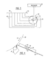
- FIG. 1 depicts the dry end of a papermaking machine in accordance with an embodiment which does not fall within the scope of the claims suitable for making tissue. The paper web, as is conventional, is dried on a Yankee dryer having a
heated dryer roll 20 rotating in the direction ofarrow 22. The web is removed from theroll 20 and preferably creped by acreping doctor 24 having adoctor blade 26. A cleaningdoctor 28 arranged after the creping doctor cleans the surface of the roll. Alternatively, thedoctor 28 can be used for removing and creping the paper web from theroll 20 when thedoctor 26 is out of service for replacement or maintenance. The web creped from thedryer roll 20 proceeds over a short draw to a drivenreel spool 30 rotating in the same direction as that of thedryer roll 20. In the draw between the crepingdoctor 24 and thereel spool 30, the web is stabilized by anactive airfoil 32 having its upstream edge adjacent thecreping doctor blade 26 and its downstream edge proximate thepaper roll 34 building on thereel spool 30. Theairfoil 32 advantageously extends across the full width of the paper web in the cross-machine direction. Theairfoil 32 is mounted so as to be rotatable about apivot axis 36 located near the upstream edge of the airfoil and extending parallel to the cross-machine direction. Thus, the airfoil can be pivoted to keep the downstream edge of the airfoil in a desired position relative to the growingpaper roll 34. Anactuator 40 provides the actuation force pivoting theairfoil 32 as the paper roll grows. Theairfoil 32 acts to suppress flutter of the web, which can occur particularly with webs of low basis weight traveling at high speeds. - The airfoil comprises an active airfoil that uses pressurized air to create a directed air flow for supporting and assisting the web's movement. Such an active airfoil is described, for example, in U.S. Patent No. 5,738,760. Briefly, the airfoil has a
panel 42 defining a web-supportingsurface 44 along which the paper web travels, and a plurality ofother walls panel 42, define an internal chamber into which pressurized air is supplied.Openings 49 in thepanel 42 discharge air from the chamber in a direction generally parallel to the web-supportingsurface 44 of the panel, thus creating a layer of moving air that supports the paper web. - FIG. 2 shows an alternative embodiment which is similar to that of FIG. 1 except that the
reel spool 30 is arranged in an upper position relative to theactive airfoil 32 so that the paper web is wound onto a lower side of thebuilding paper roll 34, which rotates in a opposite direction to that of theYankee dryer 20. - The
airfoil 32 also includes an integrated fiberoptic measuring device 60. The fiberoptic measuring device 60 comprises a plurality ofoptical fibers 62, shown schematically in FIG. 3, that are routed along theairfoil 32 either internally in the airfoil or along an outer surface other than the web-supportingsurface 44. Eachoptical fiber 62 has a sensing end for receiving light and transmitting the light along the fiber to an opposite end thereof where the transmitted light is detected and properties of the paper web are deduced therefrom. The sensing ends of thefibers 62 face the paper web traveling along the web-supportingsurface 44 of the airfoil. To this end, thepanel 42 of the airfoil includes a plurality ofapertures 46 therethrough, and the ends of theoptical fibers 62 are received in these apertures so that the sensing ends of the fibers are substantially flush with the web-supporting surface. Alternatively, the sensing ends of the fibers can be recessed below the web-supportingsurface 44; it is also possible in this case to cover theapertures 46 with a transparent cover (not shown) of glass or plastic, for example, to prevent the optical fibers from being fouled by fibers or debris, the cover being arranged to be flush with the web-supportingsurface 44. It is further possible to employ a slot-shaped aperture (or more than one such aperture) in theairfoil panel 42 and to arrange a plurality of optical fibers in a single aperture, as opposed to having a separate aperture for each fiber. - Regardless of how the
fibers 62 and aperture(s) 46 are arranged, the sensing ends of the fibers are spaced apart along the cross-machine direction, as shown in FIG. 2A. The fiber ends are spaced across substantially the entire width, or over only a portion of the width, of the paper web at predetenmined intervals, e.g., about 50-150 mm, and preferably about 100 mm. - FIG. 3 shows a
sampling device 70 that receives the opposite ends of theoptical fibers 62 and detects the light transmitted by each fiber. While the light transmitted by each fiber may be continuous, the sampling device may only periodically detect the light transmitted by any particular fiber. Thus, for example, the sampling device may be a mechanical device such as the rotary device shown in FIG. 3, in which amember 72 carrying a detector 74 revolves such that the detector 74 is brought into alignment with the end of eachoptical fiber 62 in turn. Each optical fiber thus is sampled once per revolution of themember 72. The signal sampled from each fiber is then communicated to aprocessor 80 such as a programmed computer, which is operable to deduce properties of the paper web from the signals. Thesampling device 70 can send signals to theprocessor 80 as optical signals over a fiber optic cable, in which case theprocessor 80 is operable to convert the optical signals to electrical signals that are then quantified and used in calculating properties of the paper web. Alternatively, the sampling device can convert the optical signals from the fibers into electrical signals and can send the converted electrical signals to the processor. - Although a rotary sampling device is shown, alternatively a linearly moving sampling device could be used. It is also possible to employ a sampling device that samples the fiber optic signals by electronic sampling rather than mechanical sampling. It will also be recognized that the sampling device and processor could be integrated into the same device, if desired. Furthermore, each optical fiber could have its own dedicated device continuously converting the optical signal into electrical signals so that all optical signals of all fibers are simultaneously converted into electrical signals that are either continuously or periodically monitored.
- As shown in FIG. 2, in addition to the fiber
optic measuring device 60, the dry end of the paper machine can also include further sensors 61-64 in various locations for measuring web properties. Advantageously, thesensor 61 can comprise an infrared temperature sensor placed upstream of thecreping doctor 24 for measuring web temperature prior to the web being creped from thedryer roll 20. It has been found that there is a good correlation between web moisture content and the web temperature measured by an infrared temperature sensor. Accordingly, the web temperature measured by thesensor 61 can be used for determining web moisture content going into the dry end.Sensors - The
sensors 60 measure paper properties using a reflectance technique. Measuring beams such as electromagnetic waves, ultrasonic energy, light waves in the visible or invisible spectrum, or the like, are emitted by the sensors onto the web passing along the airfoil, and reflected measuring beams from the web are received by the sensors and processed to deduce web properties. In particular, the moisture content and/or basis weight of the paper preferably are determined. Moisture content of the web can be measured using infrared sensors and techniques; such techniques are known. - Prior to the invention, the measurement of basis weight has been carried out by placing a source of radioactive isotopes on one side of the web and a detector on the other side. The detector receives the radioactive rays that pass through the web and deduces basis weight based on the amount of absorption of the radioactivity by the web. In accordance with the invention, however, measuring beams such as infrared waves are reflected from the web and the reflected measuring beams are received and analyzed using spectral analysis methods. Basis weight is correlated with changes in the spectral content of the reflected measuring beams, such that based on the spectral analysis the basis weight of the paper is deduced.
- FIG. 4 depicts an embodiment of an
active airfoil 32 having a measuringhead 50 housed within it. The measuringhead 50 comprises at least one sensor for measuring one or more properties of the paper web such as basis weight. Thehead 50 can incorporate more than one sensor, such as a basis weight sensor and a moisture or temperature sensor. The measuringhead 50 is traversable in the cross-machine direction along arail 52 or the like. The airfoil includes aslot 54 extending along the cross-machine direction aligned with the traversinghead 50. The airfoil can include amovable cover 56 for covering theslot 54 when the measuringhead 50 is not being used to measure the web property or properties. The sensors of the measuringhead 50 preferably employ a reflectance measurement technique as described previously. - FIG. 5 depicts a first embodiment of the invention in which the reel-up includes a
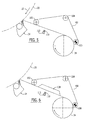
belt 100 looped about a plurality of guide rolls 102, 104, and 106, theguide roll 106 being rotatably driven for driving the belt. Theguide roll 106 is located adjacent thebuilding paper roll 34. Theguide roll 102 is spaced upstream from thepaper roll 34 and a short distance downstream from thecreping doctor 24. The portion of the loop of the belt between theguide roll 102 and theguide roll 106 acts to stabilize the web as it travels from the creping doctor to the nip defined between thebelt 100 and thepaper roll 34. FIG. 6 shows a variant in which adevice 108 for creating an underpressure is disposed within the loop of thebelt 100; in this embodiment, thebelt 100 should be permeable. Thedevice 108 can be a vacuum box, or alternatively can be a device that creates an underpressure by blowing air via the Coanda effect, such as a device marketed by Metso Corporation under the trademark Blowbox. - In the embodiments of FIGS. 5 and 6,
reflectance measuring sensors 110 are mounted on asuitable support 112 such as a beam or the like adjacent thesupport belt 100 such that the web is disposed between the sensors and the belt. Thesensors 110 can be either stationary or traversing sensors. The sensors employ the previously described reflectance techniques to measure basis weight, and can also measure one or more other parameters such as moisture content. - The
belt 100 in FIGS. 5 and 6 is in an upper position with respect to the web and paper roll, but could alternatively be in a lower position relative to the web and paper roll such that the web is supported atop the belt and is guided by the belt onto a lower side of the paper roll, which rotates counterclockwise (i.e., opposite to the direction shown in FIGS. 5 and 6). - It will be appreciated by persons skilled in the art that the principles of the invention are not limited to being applied in paper machines employing a Yankee dryer as the final dryer device, but can also be applied in other types of machines such as those employing one or more through-air dryer (TAD) units as the final dryer(s). As but one example, FIG. 7 shows a
paper machine 200 in accordance with a preferred embodiment. Themachine 200 includes a formingsection 210 having a twin-wire former. The former includes a formingroll 212, aninner wire 214 formed in an endless loop about guide rolls 216 such that the inner wire passes about a sector of the forming roll, anouter wire 218 formed in an endless loop about guide rolls 220 such that the outer wire passes about the sector of the forming roll on top of the inner wire, and ahead box 222 that discharges an aqueous suspension of papermaking fibers between the inner and outer wires just upstream of the forming roll so as to form a wet paper web between the wires. The wet web is partially dewatered by being pressed between the wires as they pass about the forming roll, and the partially dewatered web is separated from the outer wire and is carried on theinner wire 214 downstream of the forming roll to a web transfer point. At the web transfer point, the web is transferred from theinner wire 214 onto aTAD fabric 224 with the aid of asuction device 226 disposed inside the loop of the TAD fabric. TheTAD fabric 224 travels in an endless loop about guide rolls 228. The TAD fabric carrying the web thereon passes about aforaminous dryer roll 230 of each of a pair of outward-flow TAD units. An exhaust hood 232 surrounds the portion of eachdryer roll 230 about which the TAD fabric and web pass. In conventional fashion, drying air is supplied from the interior of eachdryer roll 230 radially outward through the foraminous mantle of the roll and thus through the web and TAD fabric, and is exhausted by the exhaust hoods. - The TAD fabric downstream of the second TAD unit carries the web on the outward-facing surface of the fabric. The fabric in this location extends between a pair of guide rolls 234, 236 that are disposed respectively upstream and downstream of a winding station of a reel-
up 240. The reel-up includes appropriate equipment (not shown) operable to grip and rotatably drive areel spool 242 about which the paper web is to be wound, and operable to urge the rotatably driven reel spool against theTAD fabric 224 so as to form a nip therebetween. The paper web carried on the TAD fabric passes into this nip and is thus wound onto the reel spool to build a paper roll. The reel-up is operable to move the reel spool as the paper roll builds so as to compensate for the increasing diameter of the roll. It will be appreciated that the paper machine according to FIG. 7 offers a number of advantages. First, the paper web is supported at all times on a wire or fabric, such that there are no free draws. Second, the overall length and footprint of the machine can be made small because the reel-up 240 can be close-coupled to the last TAD unit. - In accordance with the invention,
reflectance measuring sensors 250 can be placed at any or all of the positions indicated in FIG. 7 for measuring properties of the paper web supported on the lower surface of theTAD fabric 224. In this manner, the paper web properties are measured without requiring any open draw as in conventional transmission-type measurement methods. Thesensors 250 can be either stationary or traversing sensors. - The invention enables a number of advantages to be achieved over conventional paper machines. The reflectance measurement of paper basis weight and other parameters enables open draws to be eliminated and close-coupling of the reel-up to the drying section, thereby lessening the likelihood of web breaks as well as reducing overall machine length and providing a compact arrangement.
- Furthermore, the invention makes it relatively easy to detect both high- and low-frequency MD variations in web properties, because the optical fiber signals can be sampled at a rate faster than the shortest expected period of MD variations, or can even be continuously monitored if desired.
- Many modifications and other embodiments of the invention will come to mind to one skilled in the art to which this invention pertains having the benefit of the teachings presented in the foregoing descriptions and the associated drawings. For example, the embodiments illustrated and described herein as having a Yankee dryer could instead have other types of drying devices such as through-air dryers. Therefore, it is to be understood that the invention is not to be limited to the specific embodiments disclosed and that modifications and other embodiments are intended to be included within the scope of the appended claims.
Claims (12)
- A dry end of a papermaking machine, comprising:- a dryer (20; 200) for drying a paper web;- a reel-up positioned downstream of the dryer (20; 200) for winding the web to form a paper roll (34);- a web support in form of a travelling belt (100) or fabric (224) positioned between the dryer (20; 200) and the reel-up, said web support (100; 224) providing support to the web such that a first side of the web is exposed and an opposite second side of the web is in opposition to the web support (100; 224), the web support (100; 224) providing support to the web between the dryer (20; 200) and the paper roll (34),characterized in that the dry end also comprises a measuring device (110; 250) for measuring at least one property of the web, said measuring device (110; 250) being a reflectance measuring device located proximate said first side of the web, the reflectance measuring device (110; 250) emitting measuring beams onto the web on the web support and receiving reflected measuring beams from the web and deducting at least one property of the web based on the reflected measuring beams.
- The dry end of the papermaking machine according to claim 1, characterized in that the dryer is a through-air dryer (200) and the web support is a through-air drying fabric (224) arranged in an endless loop that carries a paper web through the dryer (200).
- The dry end of the papermaking machine according to claim 1, characterized in that the dryer is a Yankee dryer (20) and the web support is a belt (100) arranged in an endless loop that carries a paper web between the dryer (20) and the reel-up.
- The dry end of the papermaking machine according to any one of claims 1-3, characterized in that the web support (100,224) carries the web past a measuring station at which at least one reflectance measuring device (110; 250) is located
- The dry end of the papermaking machine according to any one of claims 1-4, characterized in that the measuring device (110; 250) comprises a fiber optic measuring device.
- The dry end of the papermaking machine according to claim 5, characterized in that the fiber optic measuring device (110; 250) comprises a plurality of optical fibers each having a sensing end, the sensing ends of the optical fibers facing the paper web.
- The dry end of the papermaking machine according to claim 1, characterized in that the web support (100; 224) forms a nip with the paper roll (34) in the reel-up and guides the web into the nip.
- A method for measuring a property of a travelling paper web in a dry end of a papermaking machine, the method comprising:- supporting the web on a web support in form at a travelling belt (100) or fabric (224) located in the dry end between a dryer (20; 200) and a reel-up of the papermaking machine such that a first side of the web is exposed and the opposite second side of the web is in opposition with the web support (100; 224), the web support (100; 224) providing support to the web between the dryer (20; 200) and a paper roll (34) held in the reel-up,characterized by- emitting measuring beams onto the first side of the web on the web support (100; 224) so as to cause the measuring beams to be reflected from the web;- receiving the measuring beams reflected from the web; and- analyzing the reflected measuring beams to measure a property of the paper.
- The method according to claim 8, wherein the dryer is a through-air dryer and the web support is a through-air drying fabric (224) arranged in an endless loop, the fabric (224) carrying the web through the through-air dryer (200), the endless loop of the fabric (224) outside the through-air dryer being arranged to carry the web on an outward-facing surface of the fabric past a measuring station at which a reflectance measuring device (250) is located for carrying out the emitting, receiving, and analyzing steps.
- The method according to claim 8, wherein the dryer is a Yankee dryer (20) and the web support is a belt (100).
- The method according to claim 8, wherein the measuring beams are directed onto the web and received from the web at each of a plurality of fixed positions spaced apart in a cross-machine direction of the web so as to measure the web at a plurality of discrete spaced locations.
- The method according to claim 8, wherein the measuring beams are directed onto the web and received from the web by a traversing sensor that travels along a cross-machine direction of the web so as to measure the web across a width thereof.
Priority Applications (1)
| Application Number | Priority Date | Filing Date | Title |
|---|---|---|---|
| EP06008268A EP1741829B1 (en) | 2002-08-08 | 2003-07-28 | Measuring arrangement in a shortened dry end of a tissue machine |
Applications Claiming Priority (3)
| Application Number | Priority Date | Filing Date | Title |
|---|---|---|---|
| US214688 | 2002-08-08 | ||
| US10/214,688 US6749723B2 (en) | 2000-06-28 | 2002-08-08 | Measuring arrangements in a shortened dry end of a tissue machine |
| PCT/SE2003/001243 WO2004015197A1 (en) | 2002-08-08 | 2003-07-28 | Measuring arrangements in a shortened dry end of a tissue machine |
Related Child Applications (1)
| Application Number | Title | Priority Date | Filing Date |
|---|---|---|---|
| EP06008268A Division EP1741829B1 (en) | 2002-08-08 | 2003-07-28 | Measuring arrangement in a shortened dry end of a tissue machine |
Publications (2)
| Publication Number | Publication Date |
|---|---|
| EP1540077A1 EP1540077A1 (en) | 2005-06-15 |
| EP1540077B1 true EP1540077B1 (en) | 2006-08-30 |
Family
ID=31714251
Family Applications (2)
| Application Number | Title | Priority Date | Filing Date |
|---|---|---|---|
| EP03784716A Expired - Lifetime EP1540077B1 (en) | 2002-08-08 | 2003-07-28 | Measuring arrangement in a shortened dry end of a tissue machine |
| EP06008268A Expired - Lifetime EP1741829B1 (en) | 2002-08-08 | 2003-07-28 | Measuring arrangement in a shortened dry end of a tissue machine |
Family Applications After (1)
| Application Number | Title | Priority Date | Filing Date |
|---|---|---|---|
| EP06008268A Expired - Lifetime EP1741829B1 (en) | 2002-08-08 | 2003-07-28 | Measuring arrangement in a shortened dry end of a tissue machine |
Country Status (9)
| Country | Link |
|---|---|
| US (1) | US6749723B2 (en) |
| EP (2) | EP1540077B1 (en) |
| JP (2) | JP2005535875A (en) |
| CN (1) | CN100346031C (en) |
| AT (2) | ATE338164T1 (en) |
| AU (1) | AU2003247321A1 (en) |
| CA (1) | CA2493797C (en) |
| DE (2) | DE60308039T2 (en) |
| WO (1) | WO2004015197A1 (en) |
Families Citing this family (24)
| Publication number | Priority date | Publication date | Assignee | Title |
|---|---|---|---|---|
| US7001487B2 (en) * | 2001-12-19 | 2006-02-21 | Kimberly-Clark Worldwide, Inc. | Method and apparatus for transporting a sheet from a dryer to a reel |
| US6797115B2 (en) * | 2002-03-29 | 2004-09-28 | Metso Paper Karlstad Ab | Method and apparatus for making a creped tissue with improved tactile qualities while improving handling of the web |
| US6743334B2 (en) * | 2002-06-11 | 2004-06-01 | Metso Paper Karlstad Aktiebolag (Ab) | Method and apparatus for making a tissue paper with improved tactile qualities while improving the reel-up process for a high bulk web |
| US8673115B2 (en) | 2002-10-07 | 2014-03-18 | Georgia-Pacific Consumer Products Lp | Method of making a fabric-creped absorbent cellulosic sheet |
| US7494563B2 (en) | 2002-10-07 | 2009-02-24 | Georgia-Pacific Consumer Products Lp | Fabric creped absorbent sheet with variable local basis weight |
| US7789995B2 (en) | 2002-10-07 | 2010-09-07 | Georgia-Pacific Consumer Products, LP | Fabric crepe/draw process for producing absorbent sheet |
| AU2003279792A1 (en) | 2002-10-07 | 2004-05-04 | Fort James Corporation | Fabric crepe process for making absorbent sheet |
| DE10326304A1 (en) * | 2003-06-11 | 2005-02-03 | Voith Fabrics Patent Gmbh | Method and device for producing a tissue web |
| US8293072B2 (en) | 2009-01-28 | 2012-10-23 | Georgia-Pacific Consumer Products Lp | Belt-creped, variable local basis weight absorbent sheet prepared with perforated polymeric belt |
| JP4663433B2 (en) * | 2005-07-12 | 2011-04-06 | キヤノン株式会社 | Image forming apparatus |
| US9295852B1 (en) | 2005-08-04 | 2016-03-29 | Pacesetter, Inc. | System and method for confirming heart arrhythmia |
| US8691323B2 (en) * | 2006-03-06 | 2014-04-08 | Nalco Company | Method and apparatus for monitoring and controlling the application of performance enhancing materials to creping cylinders |
| US8282781B2 (en) * | 2006-12-11 | 2012-10-09 | Honeywell International Inc. | Apparatus and method for stabilization of a moving sheet relative to a sensor |
| US8028988B2 (en) | 2008-01-21 | 2011-10-04 | Honeywell International Inc. | Apparatus and method for stabilizing a moving sheet relative to a sensor |
| WO2010033536A2 (en) | 2008-09-16 | 2010-03-25 | Dixie Consumer Products Llc | Food wrap basesheet with regenerated cellulose microfiber |
| US9109330B2 (en) | 2009-03-09 | 2015-08-18 | Honeywell International Inc. | Apparatus and method for measuring properties of unstabilized moving sheets |
| CN104452416B (en) * | 2014-10-24 | 2016-03-30 | 徐州工业职业技术学院 | A kind of paper machine intelligence paper injection equipment |
| US9670616B2 (en) | 2014-12-11 | 2017-06-06 | Georgia-Pacific Consumer Products Lp | Active web spreading and stabilization shower |
| JP2016112082A (en) * | 2014-12-12 | 2016-06-23 | 泉製紙株式会社 | Toilet roll paper and manufacturing method thereof |
| DE102015001008A1 (en) * | 2015-01-28 | 2016-07-28 | Andritz Küsters Gmbh | Process and apparatus for the production of wetlaid nonwovens |
| US10363583B2 (en) * | 2017-11-30 | 2019-07-30 | The Procter & Gamble Company | Method and apparatus for particulate control from moving webs |
| CN109957988A (en) * | 2017-12-14 | 2019-07-02 | 迅普精工株式会社 | Papermaking apparatus |
| FI129914B (en) * | 2018-10-26 | 2022-10-31 | Valmet Technologies Oy | Method, system, rotating machine element and computer program product for measuring the moisture of a web in a tissue machine |
| CN116075613A (en) | 2020-08-27 | 2023-05-05 | 巴克曼实验室国际公司 | Predictive control of yankee dryer chemistry and creping product quality |
Family Cites Families (45)
| Publication number | Priority date | Publication date | Assignee | Title |
|---|---|---|---|---|
| US1842889A (en) | 1928-09-01 | 1932-01-26 | Harrison R Williams | Paper machinery |
| DE2048414B2 (en) | 1970-10-02 | 1973-08-02 | Agfa Gevaert AG, 5090 Leverkusen | DEVICE FOR PHOTOELECTRIC SENSING |
| US4179330A (en) | 1978-09-05 | 1979-12-18 | Page Robert E | Apparatus for handling web material, and method |
| GB8328354D0 (en) | 1983-10-24 | 1983-11-23 | Black Clawson Int | Surface treatment of paper and paperboard |
| US4848633A (en) * | 1986-02-28 | 1989-07-18 | Thermo Electron Web Systems, Inc. | Non-contact web turning and drying apparatus |
| FI81770C (en) | 1987-05-20 | 1990-12-10 | Valmet Paper Machinery Inc | FOERFARANDE VID STYRNING AV PAPPERS RULLSTOL. |
| FI81768C (en) | 1987-05-20 | 1990-12-10 | Valmet Paper Machinery Inc | Method and apparatus for rolling paper |
| DE3807857A1 (en) * | 1988-03-10 | 1989-09-28 | Voith Gmbh J M | DRY LOT |
| US5130559A (en) * | 1989-08-26 | 1992-07-14 | Trutzschler Gmbh & Co. Kg | Method and apparatus for recognizing particle impurities in textile fiber |
| DE59004647D1 (en) | 1990-06-08 | 1994-03-24 | Beloit Technologies Inc | REWINDING DEVICE FOR ROLL CUTTING MACHINES OF THE SUPPORT ROLLER TYPE OD. DGL. |
| US5026458A (en) | 1990-08-31 | 1991-06-25 | Kimberly-Clark Corporation | Method for controlling basis weight in the production of stretchable webs |
| US5150850A (en) | 1991-05-10 | 1992-09-29 | Beloit Corporation | Method for winding a traveling web on a belted two drum wound web roll winder |
| JP2542985B2 (en) * | 1992-01-22 | 1996-10-09 | 日本製紙株式会社 | Method and apparatus for predicting dimensional stability of paper during the papermaking process |
| US5308008A (en) | 1992-03-18 | 1994-05-03 | Rueegg Anton | Method and apparatus for producing rolls |
| US5400707A (en) | 1992-10-09 | 1995-03-28 | Champion International Corporation | Apparatus for finishing a continuous sheet of paper |
| US5377428A (en) | 1993-09-14 | 1995-01-03 | James River Corporation Of Virginia | Temperature sensing dryer profile control |
| US5544841A (en) | 1994-08-18 | 1996-08-13 | Beloit Technologies, Inc. | Method and apparatus for reeling a traveling web into a wound web roll |
| US5593545A (en) | 1995-02-06 | 1997-01-14 | Kimberly-Clark Corporation | Method for making uncreped throughdried tissue products without an open draw |
| CA2221718A1 (en) | 1995-05-24 | 1996-11-28 | Voith Sulzer Papiermaschinen Gmbh | Winding device for taking up a paper web |
| SE504708C2 (en) | 1995-09-13 | 1997-04-07 | Valmet Karlstad Ab | Method and apparatus for transferring a fast-running ready-dried fiber web, in particular a tissue web, from a device and along a predetermined path to a subsequent device |
| US5681996A (en) * | 1996-08-01 | 1997-10-28 | Beloit Technologies, Inc. | Ultrasonic device for inspection of metal parts |
| DE19635216A1 (en) | 1996-08-30 | 1998-03-05 | Voith Sulzer Papiermasch Gmbh | Method and device for winding a paper web into a roll |
| FI106248B (en) | 1997-02-13 | 2000-12-29 | Valmet Corp | Rolling machine and method of rolling up paper web or equivalent |
| JP3585692B2 (en) * | 1997-02-28 | 2004-11-04 | 花王株式会社 | Method for producing bulky paper |
| DE19709963A1 (en) * | 1997-03-11 | 1998-09-17 | Qualico Gmbh | Process for monitoring the production of flat material using a near infrared spectrometer and device for carrying out this process |
| US5944273A (en) | 1997-07-03 | 1999-08-31 | Kimberly-Clark Worldwide, Inc. | Parent roll for tissue paper |
| US5891309A (en) | 1997-08-26 | 1999-04-06 | Beloit Technologies, Inc. | Web stabilizing device |
| US5931406A (en) | 1997-12-08 | 1999-08-03 | Voith Sulzer Papiertechnik Patent Gmbh | Method and winder for the continuous winding of a material web |
| US6523125B1 (en) * | 1998-01-07 | 2003-02-18 | International Business Machines Corporation | System and method for providing a hibernation mode in an information handling system |
| US6092003A (en) * | 1998-01-26 | 2000-07-18 | Honeywell-Measurex Corporation | Paper stock shear and formation control |
| DE19803137C1 (en) | 1998-01-28 | 1999-06-10 | Voith Sulzer Papiertech Patent | Reel for paper rolls |
| US6795966B1 (en) * | 1998-05-15 | 2004-09-21 | Vmware, Inc. | Mechanism for restoring, porting, replicating and checkpointing computer systems using state extraction |
| DE19844927A1 (en) * | 1998-09-30 | 2000-04-06 | Voith Sulzer Papiertech Patent | Measuring system |
| US6183601B1 (en) | 1999-02-03 | 2001-02-06 | Kimberly-Clark Worldwide, Inc. | Method of calendering a sheet material web carried by a fabric |
| DE29924829U1 (en) * | 1999-01-15 | 2005-12-08 | Voith Paper Patent Gmbh | Papermaking drying and calender stations has a controlled wetting action through water sprays according to moisture profile measurements to give the best possible lateral moisture profile with a calender directly after the drying section |
| DE19912500A1 (en) * | 1999-03-19 | 2000-09-21 | Voith Sulzer Papiertech Patent | Apparatus to monitor characteristics at a running paper web has optic fibers aligned at lateral line of measurement points to register infra red light waves to be converted into pixels at a detector for computer processing |
| US6193845B1 (en) * | 1999-05-26 | 2001-02-27 | Voith Sulzer Paper Technology North America Inc. | Blow pipe tail threading system for paper-making machines |
| FI991548A (en) * | 1999-07-06 | 2001-04-05 | Neles Field Controls Oy | Method for measuring web consistency and measuring device |
| FI106484B (en) | 1999-07-15 | 2001-02-15 | Neles Paper Automation Oy | An arrangement for measuring the properties of a moving paper web |
| US6398916B1 (en) | 1999-12-16 | 2002-06-04 | Valmet Karlstad Ab | Simplified through-air drying paper making machine having a twin wire forming section |
| US6447640B1 (en) | 2000-04-24 | 2002-09-10 | Georgia-Pacific Corporation | Impingement air dry process for making absorbent sheet |
| US6669818B2 (en) | 2000-06-28 | 2003-12-30 | Metso Paper Karlstad Ab | Shortened layout from dryer to reel in tissue machine |
| US6633976B1 (en) * | 2000-08-10 | 2003-10-14 | Phoenix Technologies Ltd. | Method of storing BIOS modules and transferring them to memory for execution |
| FI120053B (en) * | 2000-12-22 | 2009-06-15 | Metso Automation Oy | Method and apparatus for adjusting the moisture profile of a moving paper web |
| US6936137B2 (en) * | 2001-10-24 | 2005-08-30 | Honeywell International Inc. | Air clamp stabilizer for continuous web materials |
-
2002
- 2002-08-08 US US10/214,688 patent/US6749723B2/en not_active Expired - Lifetime
-
2003
- 2003-07-28 DE DE60308039T patent/DE60308039T2/en not_active Expired - Lifetime
- 2003-07-28 EP EP03784716A patent/EP1540077B1/en not_active Expired - Lifetime
- 2003-07-28 AT AT03784716T patent/ATE338164T1/en not_active IP Right Cessation
- 2003-07-28 DE DE60327116T patent/DE60327116D1/en not_active Expired - Lifetime
- 2003-07-28 AT AT06008268T patent/ATE428021T1/en active
- 2003-07-28 JP JP2004527473A patent/JP2005535875A/en active Pending
- 2003-07-28 WO PCT/SE2003/001243 patent/WO2004015197A1/en active IP Right Grant
- 2003-07-28 EP EP06008268A patent/EP1741829B1/en not_active Expired - Lifetime
- 2003-07-28 CN CNB038192616A patent/CN100346031C/en not_active Expired - Fee Related
- 2003-07-28 CA CA002493797A patent/CA2493797C/en not_active Expired - Fee Related
- 2003-07-28 AU AU2003247321A patent/AU2003247321A1/en not_active Abandoned
-
2007
- 2007-04-27 JP JP2007118318A patent/JP4857176B2/en not_active Expired - Fee Related
Also Published As
| Publication number | Publication date |
|---|---|
| EP1540077A1 (en) | 2005-06-15 |
| CN1688762A (en) | 2005-10-26 |
| CA2493797A1 (en) | 2004-02-19 |
| JP4857176B2 (en) | 2012-01-18 |
| ATE338164T1 (en) | 2006-09-15 |
| JP2007284863A (en) | 2007-11-01 |
| EP1741829A2 (en) | 2007-01-10 |
| JP2005535875A (en) | 2005-11-24 |
| WO2004015197A1 (en) | 2004-02-19 |
| US20020189775A1 (en) | 2002-12-19 |
| CN100346031C (en) | 2007-10-31 |
| DE60308039T2 (en) | 2007-03-08 |
| ATE428021T1 (en) | 2009-04-15 |
| CA2493797C (en) | 2009-02-03 |
| US6749723B2 (en) | 2004-06-15 |
| AU2003247321A1 (en) | 2004-02-25 |
| EP1741829B1 (en) | 2009-04-08 |
| DE60327116D1 (en) | 2009-05-20 |
| EP1741829A3 (en) | 2007-03-07 |
| DE60308039D1 (en) | 2006-10-12 |
Similar Documents
| Publication | Publication Date | Title |
|---|---|---|
| EP1540077B1 (en) | Measuring arrangement in a shortened dry end of a tissue machine | |
| FI120053B (en) | Method and apparatus for adjusting the moisture profile of a moving paper web | |
| FI94176C (en) | Method and apparatus for tracking the edge of a moving track | |
| CA2332478C (en) | Former and process for producing a tissue web | |
| EP2262710B1 (en) | Sheet stabilization with dual opposing cross direction air clamps | |
| US8028988B2 (en) | Apparatus and method for stabilizing a moving sheet relative to a sensor | |
| EP2262947B1 (en) | Sheet stabilizer with dual inline machine direction air clamps and backsteps | |
| US7678233B2 (en) | Machine direction sensor system with cross direction averaging | |
| US20050034831A1 (en) | Method to measure tension in a moving web and to control properties of the web | |
| JPS63145946A (en) | Measuring system and method of travelling web | |
| FI121240B (en) | Arrangements at a paper machine as well as a blow box | |
| JPH11515060A (en) | Scanning device for scanning physical properties of fibrous web | |
| FI125725B (en) | Method and apparatus for following a fiber web | |
| JP3716223B2 (en) | Web coating equipment | |
| US7396437B2 (en) | Method and system for controlling the web formation | |
| US20030121323A1 (en) | Apparatus to measure tension in a moving web and to control properties of the web | |
| EP1238150A1 (en) | Apparatus and method for determination and control of paper web qualities on a papermaking machine | |
| EP0966567B1 (en) | A device in a measuring station | |
| WO2002077624A1 (en) | Method for detecting properties of travelling sheet material |
Legal Events
| Date | Code | Title | Description |
|---|---|---|---|
| PUAI | Public reference made under article 153(3) epc to a published international application that has entered the european phase |
Free format text: ORIGINAL CODE: 0009012 |
|
| 17P | Request for examination filed |
Effective date: 20050301 |
|
| AK | Designated contracting states |
Kind code of ref document: A1 Designated state(s): AT BE BG CH CY CZ DE DK EE ES FI FR GB GR HU IE IT LI LU MC NL PT RO SE SI SK TR |
|
| AX | Request for extension of the european patent |
Extension state: AL LT LV MK |
|
| 17Q | First examination report despatched |
Effective date: 20050627 |
|
| DAX | Request for extension of the european patent (deleted) | ||
| GRAC | Information related to communication of intention to grant a patent modified |
Free format text: ORIGINAL CODE: EPIDOSCIGR1 |
|
| GRAP | Despatch of communication of intention to grant a patent |
Free format text: ORIGINAL CODE: EPIDOSNIGR1 |
|
| RTI1 | Title (correction) |
Free format text: MEASURING ARRANGEMENT IN A SHORTENED DRY END OF A TISSUE MACHINE |
|
| GRAS | Grant fee paid |
Free format text: ORIGINAL CODE: EPIDOSNIGR3 |
|
| GRAA | (expected) grant |
Free format text: ORIGINAL CODE: 0009210 |
|
| AK | Designated contracting states |
Kind code of ref document: B1 Designated state(s): AT BE BG CH CY CZ DE DK EE ES FI FR GB GR HU IE IT LI LU MC NL PT RO SE SI SK TR |
|
| PG25 | Lapsed in a contracting state [announced via postgrant information from national office to epo] |
Ref country code: IT Free format text: LAPSE BECAUSE OF FAILURE TO SUBMIT A TRANSLATION OF THE DESCRIPTION OR TO PAY THE FEE WITHIN THE PRESCRIBED TIME-LIMIT;WARNING: LAPSES OF ITALIAN PATENTS WITH EFFECTIVE DATE BEFORE 2007 MAY HAVE OCCURRED AT ANY TIME BEFORE 2007. THE CORRECT EFFECTIVE DATE MAY BE DIFFERENT FROM THE ONE RECORDED. Effective date: 20060830 Ref country code: BE Free format text: LAPSE BECAUSE OF FAILURE TO SUBMIT A TRANSLATION OF THE DESCRIPTION OR TO PAY THE FEE WITHIN THE PRESCRIBED TIME-LIMIT Effective date: 20060830 Ref country code: AT Free format text: LAPSE BECAUSE OF FAILURE TO SUBMIT A TRANSLATION OF THE DESCRIPTION OR TO PAY THE FEE WITHIN THE PRESCRIBED TIME-LIMIT Effective date: 20060830 Ref country code: RO Free format text: LAPSE BECAUSE OF FAILURE TO SUBMIT A TRANSLATION OF THE DESCRIPTION OR TO PAY THE FEE WITHIN THE PRESCRIBED TIME-LIMIT Effective date: 20060830 Ref country code: NL Free format text: LAPSE BECAUSE OF FAILURE TO SUBMIT A TRANSLATION OF THE DESCRIPTION OR TO PAY THE FEE WITHIN THE PRESCRIBED TIME-LIMIT Effective date: 20060830 Ref country code: SI Free format text: LAPSE BECAUSE OF FAILURE TO SUBMIT A TRANSLATION OF THE DESCRIPTION OR TO PAY THE FEE WITHIN THE PRESCRIBED TIME-LIMIT Effective date: 20060830 Ref country code: LI Free format text: LAPSE BECAUSE OF FAILURE TO SUBMIT A TRANSLATION OF THE DESCRIPTION OR TO PAY THE FEE WITHIN THE PRESCRIBED TIME-LIMIT Effective date: 20060830 Ref country code: SK Free format text: LAPSE BECAUSE OF FAILURE TO SUBMIT A TRANSLATION OF THE DESCRIPTION OR TO PAY THE FEE WITHIN THE PRESCRIBED TIME-LIMIT Effective date: 20060830 Ref country code: CH Free format text: LAPSE BECAUSE OF FAILURE TO SUBMIT A TRANSLATION OF THE DESCRIPTION OR TO PAY THE FEE WITHIN THE PRESCRIBED TIME-LIMIT Effective date: 20060830 Ref country code: CZ Free format text: LAPSE BECAUSE OF FAILURE TO SUBMIT A TRANSLATION OF THE DESCRIPTION OR TO PAY THE FEE WITHIN THE PRESCRIBED TIME-LIMIT Effective date: 20060830 |
|
| REG | Reference to a national code |
Ref country code: GB Ref legal event code: FG4D |
|
| REG | Reference to a national code |
Ref country code: CH Ref legal event code: EP |
|
| REG | Reference to a national code |
Ref country code: IE Ref legal event code: FG4D |
|
| REF | Corresponds to: |
Ref document number: 60308039 Country of ref document: DE Date of ref document: 20061012 Kind code of ref document: P |
|
| PG25 | Lapsed in a contracting state [announced via postgrant information from national office to epo] |
Ref country code: SE Free format text: LAPSE BECAUSE OF FAILURE TO SUBMIT A TRANSLATION OF THE DESCRIPTION OR TO PAY THE FEE WITHIN THE PRESCRIBED TIME-LIMIT Effective date: 20061130 Ref country code: BG Free format text: LAPSE BECAUSE OF FAILURE TO SUBMIT A TRANSLATION OF THE DESCRIPTION OR TO PAY THE FEE WITHIN THE PRESCRIBED TIME-LIMIT Effective date: 20061130 Ref country code: DK Free format text: LAPSE BECAUSE OF FAILURE TO SUBMIT A TRANSLATION OF THE DESCRIPTION OR TO PAY THE FEE WITHIN THE PRESCRIBED TIME-LIMIT Effective date: 20061130 |
|
| PG25 | Lapsed in a contracting state [announced via postgrant information from national office to epo] |
Ref country code: ES Free format text: LAPSE BECAUSE OF FAILURE TO SUBMIT A TRANSLATION OF THE DESCRIPTION OR TO PAY THE FEE WITHIN THE PRESCRIBED TIME-LIMIT Effective date: 20061211 |
|
| PG25 | Lapsed in a contracting state [announced via postgrant information from national office to epo] |
Ref country code: PT Free format text: LAPSE BECAUSE OF FAILURE TO SUBMIT A TRANSLATION OF THE DESCRIPTION OR TO PAY THE FEE WITHIN THE PRESCRIBED TIME-LIMIT Effective date: 20070206 |
|
| REG | Reference to a national code |
Ref country code: CH Ref legal event code: PL |
|
| NLV1 | Nl: lapsed or annulled due to failure to fulfill the requirements of art. 29p and 29m of the patents act | ||
| EN | Fr: translation not filed | ||
| PLBE | No opposition filed within time limit |
Free format text: ORIGINAL CODE: 0009261 |
|
| STAA | Information on the status of an ep patent application or granted ep patent |
Free format text: STATUS: NO OPPOSITION FILED WITHIN TIME LIMIT |
|
| 26N | No opposition filed |
Effective date: 20070531 |
|
| GBPC | Gb: european patent ceased through non-payment of renewal fee |
Effective date: 20070728 |
|
| PG25 | Lapsed in a contracting state [announced via postgrant information from national office to epo] |
Ref country code: FR Free format text: LAPSE BECAUSE OF FAILURE TO SUBMIT A TRANSLATION OF THE DESCRIPTION OR TO PAY THE FEE WITHIN THE PRESCRIBED TIME-LIMIT Effective date: 20070511 Ref country code: MC Free format text: LAPSE BECAUSE OF NON-PAYMENT OF DUE FEES Effective date: 20070731 Ref country code: GR Free format text: LAPSE BECAUSE OF FAILURE TO SUBMIT A TRANSLATION OF THE DESCRIPTION OR TO PAY THE FEE WITHIN THE PRESCRIBED TIME-LIMIT Effective date: 20061201 |
|
| PG25 | Lapsed in a contracting state [announced via postgrant information from national office to epo] |
Ref country code: GB Free format text: LAPSE BECAUSE OF NON-PAYMENT OF DUE FEES Effective date: 20070728 |
|
| PG25 | Lapsed in a contracting state [announced via postgrant information from national office to epo] |
Ref country code: EE Free format text: LAPSE BECAUSE OF FAILURE TO SUBMIT A TRANSLATION OF THE DESCRIPTION OR TO PAY THE FEE WITHIN THE PRESCRIBED TIME-LIMIT Effective date: 20060830 |
|
| PG25 | Lapsed in a contracting state [announced via postgrant information from national office to epo] |
Ref country code: IE Free format text: LAPSE BECAUSE OF NON-PAYMENT OF DUE FEES Effective date: 20070730 |
|
| PG25 | Lapsed in a contracting state [announced via postgrant information from national office to epo] |
Ref country code: FR Free format text: LAPSE BECAUSE OF FAILURE TO SUBMIT A TRANSLATION OF THE DESCRIPTION OR TO PAY THE FEE WITHIN THE PRESCRIBED TIME-LIMIT Effective date: 20060830 |
|
| PG25 | Lapsed in a contracting state [announced via postgrant information from national office to epo] |
Ref country code: CY Free format text: LAPSE BECAUSE OF FAILURE TO SUBMIT A TRANSLATION OF THE DESCRIPTION OR TO PAY THE FEE WITHIN THE PRESCRIBED TIME-LIMIT Effective date: 20060830 Ref country code: LU Free format text: LAPSE BECAUSE OF NON-PAYMENT OF DUE FEES Effective date: 20070728 |
|
| PG25 | Lapsed in a contracting state [announced via postgrant information from national office to epo] |
Ref country code: HU Free format text: LAPSE BECAUSE OF FAILURE TO SUBMIT A TRANSLATION OF THE DESCRIPTION OR TO PAY THE FEE WITHIN THE PRESCRIBED TIME-LIMIT Effective date: 20070301 Ref country code: TR Free format text: LAPSE BECAUSE OF FAILURE TO SUBMIT A TRANSLATION OF THE DESCRIPTION OR TO PAY THE FEE WITHIN THE PRESCRIBED TIME-LIMIT Effective date: 20060830 |
|
| PGFP | Annual fee paid to national office [announced via postgrant information from national office to epo] |
Ref country code: FI Payment date: 20090716 Year of fee payment: 7 |
|
| PG25 | Lapsed in a contracting state [announced via postgrant information from national office to epo] |
Ref country code: FI Free format text: LAPSE BECAUSE OF NON-PAYMENT OF DUE FEES Effective date: 20100728 |
|
| REG | Reference to a national code |
Ref country code: DE Ref legal event code: R082 Ref document number: 60308039 Country of ref document: DE Representative=s name: LORENZ & KOLLEGEN PATENTANWAELTE PARTNERSCHAFT, DE |
|
| REG | Reference to a national code |
Ref country code: DE Ref legal event code: R082 Ref document number: 60308039 Country of ref document: DE Representative=s name: TBK, DE Effective date: 20130709 Ref country code: DE Ref legal event code: R081 Ref document number: 60308039 Country of ref document: DE Owner name: METSO PAPER SWEDEN AB, SE Free format text: FORMER OWNER: METSO PAPER KARLSTAD AB, KARLSTAD, SE Effective date: 20130709 Ref country code: DE Ref legal event code: R082 Ref document number: 60308039 Country of ref document: DE Representative=s name: TBK, DE Effective date: 20130828 Ref country code: DE Ref legal event code: R081 Ref document number: 60308039 Country of ref document: DE Owner name: VALMET AB, SE Free format text: FORMER OWNER: METSO PAPER KARLSTAD AB, KARLSTAD, SE Effective date: 20130709 |
|
| REG | Reference to a national code |
Ref country code: DE Ref legal event code: R082 Ref document number: 60308039 Country of ref document: DE Representative=s name: TBK, DE Effective date: 20140102 Ref country code: DE Ref legal event code: R081 Ref document number: 60308039 Country of ref document: DE Owner name: METSO PAPER SWEDEN AB, SE Free format text: FORMER OWNER: METSO PAPER SWEDEN AB, KARLSTAD, SE Effective date: 20140102 Ref country code: DE Ref legal event code: R081 Ref document number: 60308039 Country of ref document: DE Owner name: VALMET AB, SE Free format text: FORMER OWNER: METSO PAPER SWEDEN AB, KARLSTAD, SE Effective date: 20140102 |
|
| REG | Reference to a national code |
Ref country code: DE Ref legal event code: R082 Ref document number: 60308039 Country of ref document: DE Representative=s name: TBK, DE |
|
| REG | Reference to a national code |
Ref country code: DE Ref legal event code: R081 Ref document number: 60308039 Country of ref document: DE Owner name: VALMET AB, SE Free format text: FORMER OWNER: METSO PAPER SWEDEN AB, SUNDSVALL, SE Effective date: 20140317 Ref country code: DE Ref legal event code: R082 Ref document number: 60308039 Country of ref document: DE Representative=s name: TBK, DE Effective date: 20140317 |
|
| PGFP | Annual fee paid to national office [announced via postgrant information from national office to epo] |
Ref country code: DE Payment date: 20140724 Year of fee payment: 12 |
|
| REG | Reference to a national code |
Ref country code: DE Ref legal event code: R119 Ref document number: 60308039 Country of ref document: DE |
|
| PG25 | Lapsed in a contracting state [announced via postgrant information from national office to epo] |
Ref country code: DE Free format text: LAPSE BECAUSE OF NON-PAYMENT OF DUE FEES Effective date: 20160202 |