EP1531247A2 - Electromechanical control system, particularly for marine applications - Google Patents
Electromechanical control system, particularly for marine applications Download PDFInfo
- Publication number
- EP1531247A2 EP1531247A2 EP04105033A EP04105033A EP1531247A2 EP 1531247 A2 EP1531247 A2 EP 1531247A2 EP 04105033 A EP04105033 A EP 04105033A EP 04105033 A EP04105033 A EP 04105033A EP 1531247 A2 EP1531247 A2 EP 1531247A2
- Authority
- EP
- European Patent Office
- Prior art keywords
- control
- beta
- lever
- signal
- monitoring unit
- Prior art date
- Legal status (The legal status is an assumption and is not a legal conclusion. Google has not performed a legal analysis and makes no representation as to the accuracy of the status listed.)
- Granted
Links
Images


Classifications
-
- F—MECHANICAL ENGINEERING; LIGHTING; HEATING; WEAPONS; BLASTING
- F02—COMBUSTION ENGINES; HOT-GAS OR COMBUSTION-PRODUCT ENGINE PLANTS
- F02D—CONTROLLING COMBUSTION ENGINES
- F02D41/00—Electrical control of supply of combustible mixture or its constituents
- F02D41/24—Electrical control of supply of combustible mixture or its constituents characterised by the use of digital means
- F02D41/2406—Electrical control of supply of combustible mixture or its constituents characterised by the use of digital means using essentially read only memories
- F02D41/2425—Particular ways of programming the data
-
- B—PERFORMING OPERATIONS; TRANSPORTING
- B63—SHIPS OR OTHER WATERBORNE VESSELS; RELATED EQUIPMENT
- B63H—MARINE PROPULSION OR STEERING
- B63H21/00—Use of propulsion power plant or units on vessels
- B63H21/21—Control means for engine or transmission, specially adapted for use on marine vessels
- B63H21/213—Levers or the like for controlling the engine or the transmission, e.g. single hand control levers
-
- F—MECHANICAL ENGINEERING; LIGHTING; HEATING; WEAPONS; BLASTING
- F02—COMBUSTION ENGINES; HOT-GAS OR COMBUSTION-PRODUCT ENGINE PLANTS
- F02D—CONTROLLING COMBUSTION ENGINES
- F02D11/00—Arrangements for, or adaptations to, non-automatic engine control initiation means, e.g. operator initiated
- F02D11/06—Arrangements for, or adaptations to, non-automatic engine control initiation means, e.g. operator initiated characterised by non-mechanical control linkages, e.g. fluid control linkages or by control linkages with power drive or assistance
- F02D11/10—Arrangements for, or adaptations to, non-automatic engine control initiation means, e.g. operator initiated characterised by non-mechanical control linkages, e.g. fluid control linkages or by control linkages with power drive or assistance of the electric type
- F02D11/105—Arrangements for, or adaptations to, non-automatic engine control initiation means, e.g. operator initiated characterised by non-mechanical control linkages, e.g. fluid control linkages or by control linkages with power drive or assistance of the electric type characterised by the function converting demand to actuation, e.g. a map indicating relations between an accelerator pedal position and throttle valve opening or target engine torque
-
- F—MECHANICAL ENGINEERING; LIGHTING; HEATING; WEAPONS; BLASTING
- F02—COMBUSTION ENGINES; HOT-GAS OR COMBUSTION-PRODUCT ENGINE PLANTS
- F02D—CONTROLLING COMBUSTION ENGINES
- F02D41/00—Electrical control of supply of combustible mixture or its constituents
- F02D41/22—Safety or indicating devices for abnormal conditions
-
- F—MECHANICAL ENGINEERING; LIGHTING; HEATING; WEAPONS; BLASTING
- F02—COMBUSTION ENGINES; HOT-GAS OR COMBUSTION-PRODUCT ENGINE PLANTS
- F02D—CONTROLLING COMBUSTION ENGINES
- F02D41/00—Electrical control of supply of combustible mixture or its constituents
- F02D41/24—Electrical control of supply of combustible mixture or its constituents characterised by the use of digital means
- F02D41/2406—Electrical control of supply of combustible mixture or its constituents characterised by the use of digital means using essentially read only memories
- F02D41/2409—Addressing techniques specially adapted therefor
- F02D41/2416—Interpolation techniques
-
- F—MECHANICAL ENGINEERING; LIGHTING; HEATING; WEAPONS; BLASTING
- F02—COMBUSTION ENGINES; HOT-GAS OR COMBUSTION-PRODUCT ENGINE PLANTS
- F02D—CONTROLLING COMBUSTION ENGINES
- F02D41/00—Electrical control of supply of combustible mixture or its constituents
- F02D41/24—Electrical control of supply of combustible mixture or its constituents characterised by the use of digital means
- F02D41/2406—Electrical control of supply of combustible mixture or its constituents characterised by the use of digital means using essentially read only memories
- F02D41/2409—Addressing techniques specially adapted therefor
- F02D41/2422—Selective use of one or more tables
-
- F—MECHANICAL ENGINEERING; LIGHTING; HEATING; WEAPONS; BLASTING
- F02—COMBUSTION ENGINES; HOT-GAS OR COMBUSTION-PRODUCT ENGINE PLANTS
- F02D—CONTROLLING COMBUSTION ENGINES
- F02D41/00—Electrical control of supply of combustible mixture or its constituents
- F02D41/24—Electrical control of supply of combustible mixture or its constituents characterised by the use of digital means
- F02D41/26—Electrical control of supply of combustible mixture or its constituents characterised by the use of digital means using computer, e.g. microprocessor
- F02D41/266—Electrical control of supply of combustible mixture or its constituents characterised by the use of digital means using computer, e.g. microprocessor the computer being backed-up or assisted by another circuit, e.g. analogue
-
- F—MECHANICAL ENGINEERING; LIGHTING; HEATING; WEAPONS; BLASTING
- F02—COMBUSTION ENGINES; HOT-GAS OR COMBUSTION-PRODUCT ENGINE PLANTS
- F02D—CONTROLLING COMBUSTION ENGINES
- F02D41/00—Electrical control of supply of combustible mixture or its constituents
- F02D41/22—Safety or indicating devices for abnormal conditions
- F02D2041/228—Warning displays
Abstract
Description
Claims (52)
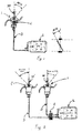
- An electromechanical control system for watercrafts, motorboats, ships or the like, having at least: a control station, an engine, an electromechanical actuator associated to said engine, a signal transmission device for transmitting a control signal generated by the control station to an electronic control and monitoring unit as a function of the control signal and transmitted to said electromechanical actuator for actuating the signal, and further having a signal transmission device for transmitting an actuating signal, generated by the electronic control and monitoring unit as a function of the control signal and transmitted to said electromechanical actuator for actuating the control, characterized in that said electronic control and monitoring unit establishes a unique correspondence between the control signal and the actuating signal by using a table of correspondence between discretized values of control signals and actuating signals and/or by determining the actuating signal value from the control signal by means of a mathematical function.
- A system according to claim 1, characterized in that said control station has a control device for the user to set the control or input signal.
- An electromechanical control system for watercrafts, motorboats, ships or the like as claimed in claim 1 or 2, characterized in that said control setting device is able to be displaced relative to a fixed reference, its displacement being related to a control signal value, with electric, electronic and/or electromechanical means being associated to said control device, for detecting the displacement of the control device and for generating a control signal that is uniquely related with said displacement.
- A system as claimed in one or more of the preceding claims, characterized in that said control signal is transmitted to the electronic control and monitoring unit, through said signal transmission devices in the form of a CAN BUS.
- A system as claimed in one or more of the preceding claims, characterized in that said actuating signal is transmitted by the electronic control and monitoring unit to said actuator, through said signal transmission devices in the form of a CAN BUS.
- A system as claimed in one or more of the preceding claims, characterized in that said control signal setting device is a control lever which is capable of being angularly displaced (BETA) relative to a stationary reference.
- A system as claimed in one or more of the preceding claims, characterized in that said actuator has a pivoting actuating lever which acts on the device for delivering fuel and/or fuel-air mixture of/to the engine and/or on a flow meter or control device having a flow metering or controlling member that can be angularly displaced about a predetermined axis, which lever and/or which flow meter or control device take a predetermined angular position (ALFA) relative to a stationary reference, as a function of the angular position (BETA) of the control lever relative to the corresponding stationary reference.
- A system as claimed in one or more of the preceding claims, characterized in that said electronic control and monitoring unit is a programmable electronic unit.
- A system as claimed in one or more of the preceding claims, characterized in that the electronic control and monitoring unit stores one or more tables of unique correlation between the control signal corresponding to the angular position (BETA) of the control lever and the actuating signal corresponding to the angular position (ALFA) of the actuating lever and/or the flow meter or control device and/or the electronic control unit stores, in the form of a program code to be executed thereby, at least one or more different functions of unique correlation between the control signal corresponding to the angular position (BETA) of the control lever and the actuating signal corresponding to the angular position (ALFA) of the actuating lever and/or the flow meter or control device, the corresponding actuating signal being determined from time to time, for each control signal, by using one of said correlation functions.
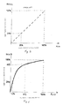
- A system as claimed in one or more of the preceding claims, characterized in that said mathematical correspondence functions establish such a unique correspondence between said control signal and said actuating signal that ALFA = f(BETA), where BETA is the control lever displacement angle and ALFA is the opening angle of a throttle and where f is any mathematical function having BETA as a variable.
- A system as claimed in one or more of the preceding claims, characterized in that at least one memory is associated to said electronic control unit, with means for loading in such memory one or more correlation functions f(BETA) and/or one or more tables of correspondence between the angle of the actuating lever and/or of the flow meter or control device and/or of at least one throttle (ALFA) and the angle (BETA) of a control lever.
- A system as claimed in one or more of the preceding claims, characterized in that the control station is associated to means for selecting at least one of the different functions f(BETA) or tables of correlation between the control signal and the actuating signal, i.e. between the angle (BETA) of the control lever and the angle (ALFA) of the actuating lever and/or of the flow meter or control device and/or of at least one throttle.
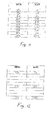
- A system as claimed in claim 12, characterized in that said selectors are a set of DIP switches, a certain number of combinations of switching conditions of the switches of the set being defined, and each of said combinations being uniquely related as a selection code with one of the various correlation functions f (BETA) or a different table of correspondence, and yet each switching combination of the set of DIP switches providing a control to load said correlation function or correlation table in the working storage of the control electronics.
- A system as claimed in one or more of the preceding claims, characterized in that the correlation functions and/or the tables of correlation and the selection codes formed by the switching combinations of the set of DIP switches are stored in a nonvolatile memory.
- A system as claimed in one or more of the preceding claims, characterized in that said electronic control unit may be programmed several times.
- A method for controlling the throttle opening in a marine engine, characterized in that it includes the steps of:setting an angular position (BETA) of a control lever;using the value of said angular position (BETA) ad the argument of a mathematical function ALFA = f(BETA);carrying out the mathematical computation to determine the result ALFAdisplacing a lever which actuates the fuel-air mixture flow control means and/or displacing a device for metering or controlling said flow and/or opening the throttle to an extent corresponding to an angular displacement equal to the result (ALFA) as determined by the mathematical function ALFA = f(BETA).
- A method for controlling the throttle opening in a marine engine, characterized in that it includes the steps of:setting an angular position (BETA) of a control lever;comparing the value of said angular position (BETA) with a table of correspondence between the angular position (BETA) of the control lever and the angular position (ALFA) of a lever for actuating the fuel-air mixture flow control means and/or a device for metering or controlling said flow and/or a throttle.determining the value of the angular position (ALFA) of a lever for actuating the fuel-air mixture flow control means and/or a device for metering or controlling said flow and/or a throttle, which corresponds to the value of the angular position (BETA) of the control lever in the table of correspondence;displacing a lever which actuates the fuel-air mixture flow control means and/or displacing a device for metering or controlling said flow and/or opening the throttle in the angular position (ALFA) as an extent corresponding to an angular displacement equal to the result (ALFA) as determined by the mathematical function ALFA = f(BETA).
- A system as claimed in one or more of the preceding claims, characterized in that said correlation function f(BETA) is such that the power that is actually delivered by the engine is linear with the angular displacement of the control lever.
- A system as claimed in one or more of the preceding claims, characterized in that, when maneuvering the watercraft, said correlation function f (BETA) is such that the maximum angular displacement (BETA) of the control lever corresponds to an angular position (ALFA) of a lever for actuating the fuel-air mixture flow control means and/or a device for metering or controlling said flow and/or a throttle, which is less than 100% of the maximum obtainable opening, so that the maximum power delivered by the engine is low enough as to allow safe maneuvering of the watercraft.
- A system as claimed in one or more of the preceding claims, characterized in that a negative value of the angular displacement (BETA) corresponds to a reversal of the propeller motion by known devices.
- A system as claimed in one or more of the preceding claims, characterized in that a positive value of the angular displacement (BETA) of the control lever is associated, by the electronic control and monitoring unit, to a first correlation function of the ALFA=f(BETA) type, and a negative value of the angular displacement (Beta) of the control lever is associated, by the electronic control and monitoring unit, to a second correlation function ALFA=f' (BETA).
- An electromechanical system as claimed in claim 21, characterized in that the first correlation function f' (BETA) is identical to the second correlation function f(BETA).
- A system as claimed in claim 21, characterized in that the first correlation function f(BETA) is different from the second correlation function f' (BETA) .
- An electromechanical system, particularly for marine applications, comprising at least one control station having at least one control device, e.g. one control lever, for controlling the power delivered by the engine or the number of revolutions of the engine and/or for setting the direction of rotation thereof, which control device has transducers for generating electrical control signals and which system further comprises an actuator that actuates fuel-air mixture flow control means of at least one engine, said control station and said actuator being connected by a CAN bus for transmitting the control signal from the control device to the actuator, and which system further comprises an electronic control and monitoring unit, characterized in that said electronic control and monitoring unit has a circuit for checking that proper communication exists between said actuator and said control station.
- A system as claimed in claim 24, characterized in that it comprises an actuator for controlling navigation condition setting means, providing at least two navigation conditions, the forward and the neutral condition, whereas the electronic control unit comprises means for automatically generating the actuating signal corresponding to the minimum engine rpm setting, i.e. corresponding to a setting of the fuel-air mixture flow control means which corresponds to said minimum rpm condition, and corresponding to the neutral transmission setting, and for transmitting said signal to the actuator of the fuel-air mixture flow control means as well as the navigation condition.
- A system as claimed in claims 24 and 25, characterized in that acoustic and/or visual means are provided for signaling an error condition, which means are controlled by the electronic control unit and are actuated thereby when said control unit detects an error in the communication between said control station and said actuator.
- A system as claimed in one or more of claims 25 to 26, characterized in that the engine power control lever remains in the minimum opening condition and the inverter remains in the neutral position until the error is acknowledged by the electronic control and monitoring unit and/or the user possibly selects a different control station.
- A system as claimed in claims 1 to 24, characterized in that it comprises, in combination therewith, an electronic control and monitoring unit as claimed in one or more of claims 25 to 28.
- A system as claimed in one or more of the preceding claims, characterized in that two, three or more control stations are provided.
- A system as claimed in claim 29, characterized in that said control stations are connected in series by CAN buses.
- An electromechanical system as claimed in claim 30, characterized in that said control stations have toggle means for selecting/unselecting the operating control station, whose toggle signal is transmitted to said electronic control unit and allow said electronic control unit to identify the user selected station.
- A system as claimed in the preceding claim, characterized in that the control signal processed by said electronic control unit as claimed in one or more of the preceding claims is the control signal that corresponds to the angular displacement (BETA) of the control lever of the station selected by the toggle means.
- A system as claimed in claim 32, characterized in that control stations with two or more control levers are provided.
- A system as claimed in claim 33, characterized in that each control lever of each control station is connected to an engine power controlling actuator, which is connected thereto by a CAN bus.
- A system as claimed in one or more of the preceding claims, characterized in that it may have a single electronic control and monitoring unit, associated to two or more control stations, each having one, two or more control levers, said electronic control and monitoring unit being designed and programmed in such a manner that several correlation functions f(BETA) and f' (BETA) may be provided for determining the angular position (ALFA) of an actuating lever and/or a device for metering or controlling the fuel-air mixture flow to the engine, i.e. the throttle of a throttle valve depending on the angular position (BETA) of the different control levers.
- A system as claimed in one or more of the preceding claims, characterized in that only certain angular control lever displacement values (BETA) and certain angular positions (ALFA) of a lever for actuating the fuel-air mixture flow control means and/or a device for metering or controlling said flow and/or a throttle are entered in the table of correspondence, the intermediate values between said set values being determined by the electronic control and monitoring unit by an interpolation between said set values, which interpolation may be a linear, a least-squares interpolation or any other type of interpolation, other than the ones mentioned above.
- A system as claimed in one or more of the preceding claims, characterized in that the control station is associated to an input means for setting the values of angular displacement (BETA) of the control lever, such as a keypad and/or a sequence of buttons and/or levers, the values of the table of correspondence being set on said input means.
- A system as claimed in one or more of the preceding claims, characterized in that a feedback is provided to the electronic control and monitoring unit.
- A system as claimed in one or more of the preceding claims, characterized in that said feedback to the electronic control and monitoring unit is a feedback that depends on such parameters as the engine rpm, i.e. the number of operating revolutions per minute of the engine.
- A system as claimed in one or more of the preceding claims, characterized in that said feedback is used by the electronic control and monitoring unit to check that the signal is transmitted properly.
- A system as claimed in one or more of the preceding claims, characterized in that said engine rpm feedback signal is used by the electronic control and monitoring unit to generate a table of correspondence by associating the number of revolutions corresponding to a predetermined displacement ALFA with an angular displacement BETA set by the user by means of the control lever.
- A method for generating a table of correspondence in an electronic control and monitoring unit as claimed in one or more of the preceding claims, characterized in that it includes the steps of:a- setting a desired engine rpm corresponding to an angular displacement BETA of the control lever;b- selecting a so-called "programming" mode, by pushing one or more buttons on the control station;c- discontinuing the control lever signal, so that the lever may pivot freely without transmitting any control signal to the actuator;d- setting a preferred angular displacement BETA of the control lever;e- reading from the feedback the engine rpm and/or the angular displacement (ALFA) of the actuating lever that corresponds to the selected angular displacement (BETA);f- generating a table of correspondence which uniquely relates the angular displacement of the control lever (BETA) to the engine rpm and/or the angular displacement of the actuator lever (ALFA) selected during the "programming" mode;g- repeating the steps a, c, d, e, g, if required,f- saving the table of correspondence so obtained;h- selecting the return to the normal mode of the system.
- A system as claimed in one or more of the preceding claims, characterized in that said electronic control and monitoring unit has means for detecting and coding errors and means for storing error code/s and rate/s of occurrence of the corresponding error/s and/or means for comparing said error code/s and rate/s of occurrence of the corresponding error/s with a preset table.
- A system as claimed in one or more of the preceding claims, characterized in that said electronic control and monitoring unit associates a code to any detected error type, and stores the rate of occurrence of the coded error.
- A system as claimed in one or more of the preceding claims, characterized in that operation sensors are associated to selected watercraft subsystems, such as preferably the engine and/or the actuator and/or other subsystems, for detecting proper operation and/or subsystem operation parameter/s.
- A system as claimed in one or more of the preceding claims, characterized in that the electronic control and monitoring unit receives input signals from said operation sensors and assigns a code to each error and monitors the rate of occurrence thereof.
- A system as claimed in one or more of the preceding claims, characterized in that the electronic control and monitoring unit stores the time curve of the operation parameters transmitted by the sensors that detect the operation of the subsystems wherewith they are associated.
- A system as claimed in one or more of the preceding claims, characterized in that the electronic control and monitoring unit compares the actual operation parameter curve with the stored curve, and stores any detected abnormality, i.e. any excessive difference of the detected parameters from the stored average of identical parameters.
- A system as claimed in one or more of the preceding claims, characterized in that the electronic control and monitoring unit provides a list of the detected malfunctions and/or errors.
- A system as claimed in one or more of the preceding claims, characterized in that the electronic control and monitoring unit compares the list of the detected errors and/or malfunctions with a stored list and provides a list of maintenance actions to be taken by the user.
- A system as claimed in one or more of the preceding claims, characterized in that the electronic control and monitoring unit informs the user about the rate of occurrence and type of the detected errors and/malfunctions, by using special codes.
- A system as claimed in one or more of the preceding claims, characterized in that, in lieu of control and/or actuating levers and/or of flow meter or control devices or of a throttle of a throttle valve, control and/or actuating and/or meter devices are provided which perform linear strokes instead of pivotal motions or combinations of linear and curved strokes, there being provided at least one table or at least one function of unique correlation between a signal corresponding to the stroke of the control device and the actuating signal that determines the uniquely correlated displacement of the actuator and/or the device for metering and/or controlling the fuel-air mixture flow to the engine.
Applications Claiming Priority (2)
| Application Number | Priority Date | Filing Date | Title |
|---|---|---|---|
| IT000046A ITSV20030046A1 (en) | 2003-11-14 | 2003-11-14 | ELECTROMECHANICAL CONTROL SYSTEM IN PARTICULAR FOR |
| ITSV20030046 | 2003-11-14 |
Publications (3)
| Publication Number | Publication Date |
|---|---|
| EP1531247A2 true EP1531247A2 (en) | 2005-05-18 |
| EP1531247A3 EP1531247A3 (en) | 2008-06-11 |
| EP1531247B1 EP1531247B1 (en) | 2010-09-01 |
Family
ID=34430805
Family Applications (1)
| Application Number | Title | Priority Date | Filing Date |
|---|---|---|---|
| EP04105033A Expired - Fee Related EP1531247B1 (en) | 2003-11-14 | 2004-10-14 | Electromechanical control system, particularly for marine applications |
Country Status (3)
| Country | Link |
|---|---|
| US (1) | US20050143875A1 (en) |
| EP (1) | EP1531247B1 (en) |
| IT (1) | ITSV20030046A1 (en) |
Cited By (1)
| Publication number | Priority date | Publication date | Assignee | Title |
|---|---|---|---|---|
| US9805524B2 (en) | 2016-03-11 | 2017-10-31 | General Electric Company | Systems and methods for displaying a fault analysis instructions of an engine control subsystem |
Families Citing this family (5)
| Publication number | Priority date | Publication date | Assignee | Title |
|---|---|---|---|---|
| US7380538B1 (en) | 2006-12-22 | 2008-06-03 | Bombardier Recreational Products Inc. | Reverse operation of a vehicle |
| US7315779B1 (en) | 2006-12-22 | 2008-01-01 | Bombardier Recreational Products Inc. | Vehicle speed limiter |
| US7530345B1 (en) | 2006-12-22 | 2009-05-12 | Bombardier Recreational Products Inc. | Vehicle cruise control |
| IT1395074B1 (en) * | 2009-08-06 | 2012-09-05 | Ultraflex Spa | SINGLE-LEVER CONTROL FOR THE COMBINED CONTROL OF THE POWER SUPPLY CONDITION OF ONE OR MORE ENGINES AND OF A GEAR SHIFT INVERTER MECHANISM |
| US8762022B1 (en) * | 2012-08-17 | 2014-06-24 | Brunswick Corporation | Marine propulsion system with efficient engine speed delta |
Citations (4)
| Publication number | Priority date | Publication date | Assignee | Title |
|---|---|---|---|---|
| US4856477A (en) | 1987-07-24 | 1989-08-15 | Nissan Motor Company, Limited | Throttle control system for automotive internal combustion engine with fail-safe mechanism |
| DE4417802A1 (en) | 1993-05-21 | 1994-11-24 | Toyota Motor Co Ltd | Engine-power control device |
| US6298824B1 (en) | 1999-10-21 | 2001-10-09 | Brunswick Corporation | Engine control system using an air and fuel control strategy based on torque demand |
| CA2417380A1 (en) | 2002-02-04 | 2003-08-04 | Honda Giken Kogyo Kabushiki Kaisha | Jet propulsion boat |
Family Cites Families (9)
| Publication number | Priority date | Publication date | Assignee | Title |
|---|---|---|---|---|
| JP3065414B2 (en) * | 1991-12-25 | 2000-07-17 | 三信工業株式会社 | Remote control device for ship propulsion |
| US6431930B1 (en) * | 1998-09-29 | 2002-08-13 | Bombardier Motor Corporation Of America | Electronic control system for boats |
| US6273771B1 (en) * | 2000-03-17 | 2001-08-14 | Brunswick Corporation | Control system for a marine vessel |
| US6587765B1 (en) * | 2001-06-04 | 2003-07-01 | Teleflex Incorporated | Electronic control system for marine vessels |
| JP3967221B2 (en) * | 2002-07-22 | 2007-08-29 | ヤマハマリン株式会社 | Ship propulsion control device |
| US6704643B1 (en) * | 2002-09-16 | 2004-03-09 | Brunswick Corporation | Adaptive calibration strategy for a manually controlled throttle system |
| JP2004218476A (en) * | 2003-01-10 | 2004-08-05 | Mitsubishi Electric Corp | Electronically controlled driving device |
| US6757606B1 (en) * | 2003-06-02 | 2004-06-29 | Brunswick Corporation | Method for controlling the operation of an internal combustion engine |
| US6881106B1 (en) * | 2003-10-27 | 2005-04-19 | Brunswick Corporation | Power fault detection system for a communication bus |
-
2003
- 2003-11-14 IT IT000046A patent/ITSV20030046A1/en unknown
-
2004
- 2004-10-14 EP EP04105033A patent/EP1531247B1/en not_active Expired - Fee Related
- 2004-11-15 US US10/987,216 patent/US20050143875A1/en not_active Abandoned
Patent Citations (4)
| Publication number | Priority date | Publication date | Assignee | Title |
|---|---|---|---|---|
| US4856477A (en) | 1987-07-24 | 1989-08-15 | Nissan Motor Company, Limited | Throttle control system for automotive internal combustion engine with fail-safe mechanism |
| DE4417802A1 (en) | 1993-05-21 | 1994-11-24 | Toyota Motor Co Ltd | Engine-power control device |
| US6298824B1 (en) | 1999-10-21 | 2001-10-09 | Brunswick Corporation | Engine control system using an air and fuel control strategy based on torque demand |
| CA2417380A1 (en) | 2002-02-04 | 2003-08-04 | Honda Giken Kogyo Kabushiki Kaisha | Jet propulsion boat |
Cited By (1)
| Publication number | Priority date | Publication date | Assignee | Title |
|---|---|---|---|---|
| US9805524B2 (en) | 2016-03-11 | 2017-10-31 | General Electric Company | Systems and methods for displaying a fault analysis instructions of an engine control subsystem |
Also Published As
| Publication number | Publication date |
|---|---|
| US20050143875A1 (en) | 2005-06-30 |
| EP1531247A3 (en) | 2008-06-11 |
| ITSV20030046A1 (en) | 2005-05-15 |
| EP1531247B1 (en) | 2010-09-01 |
Similar Documents
| Publication | Publication Date | Title |
|---|---|---|
| US6704643B1 (en) | Adaptive calibration strategy for a manually controlled throttle system | |
| US10507898B1 (en) | Lockout for remote controls on marine vessels | |
| US7442102B2 (en) | Boat | |
| US7677937B2 (en) | Operator control system of boat | |
| US20190353093A1 (en) | Watercraft and system for operating same | |
| US7559815B2 (en) | Remote control device, remote control device side ECU and watercraft | |
| US7549901B2 (en) | Outboard motor control system | |
| US8032271B2 (en) | Boat propulsion unit and boat | |
| EP1531247B1 (en) | Electromechanical control system, particularly for marine applications | |
| US7860616B2 (en) | Remote control system for a watercraft | |
| US10155578B1 (en) | Method and system for controlling a marine drive during shift sensor fault | |
| US20080233812A1 (en) | Controller for boat propulsion system and boat propulsion system | |
| US8712671B2 (en) | Engine RPM control device | |
| JP4403195B2 (en) | Small vessel shift / tidal device | |
| JP4641312B2 (en) | Electronic controller for ship drive | |
| JP2001507780A (en) | Control system for transmission and transmission adapted for it | |
| US11312461B1 (en) | Boat maneuvering control system for boat and boat maneuvering control method for boat | |
| US9290254B2 (en) | Method and arrangement for controlling a ship propulsion system | |
| KR101091622B1 (en) | Method and apparatus of a vehicle transmission for communicating lever position | |
| JP4454594B2 (en) | Transmission control device | |
| US4794808A (en) | Transmission control | |
| US11884375B2 (en) | Multi-layer gear determination system | |
| US9278746B1 (en) | Systems and methods for redundant drive-by-wire control of marine engines | |
| CA2619847C (en) | Outboard motor control system | |
| US7556546B2 (en) | Remote control system for boat |
Legal Events
| Date | Code | Title | Description |
|---|---|---|---|
| PUAI | Public reference made under article 153(3) epc to a published international application that has entered the european phase |
Free format text: ORIGINAL CODE: 0009012 |
|
| AK | Designated contracting states |
Kind code of ref document: A2 Designated state(s): AT BE BG CH CY CZ DE DK EE ES FI FR GB GR HU IE IT LI LU MC NL PL PT RO SE SI SK TR |
|
| AX | Request for extension of the european patent |
Extension state: AL HR LT LV MK |
|
| RIC1 | Information provided on ipc code assigned before grant |
Ipc: B63H 21/22 20060101ALI20080211BHEP Ipc: F02D 41/24 20060101ALI20080211BHEP Ipc: F02D 11/10 20060101AFI20050318BHEP Ipc: F02D 41/26 20060101ALI20080211BHEP Ipc: F02D 41/22 20060101ALI20080211BHEP |
|
| PUAL | Search report despatched |
Free format text: ORIGINAL CODE: 0009013 |
|
| AK | Designated contracting states |
Kind code of ref document: A3 Designated state(s): AT BE BG CH CY CZ DE DK EE ES FI FR GB GR HU IE IT LI LU MC NL PL PT RO SE SI SK TR |
|
| AX | Request for extension of the european patent |
Extension state: AL HR LT LV MK |
|
| 17P | Request for examination filed |
Effective date: 20080908 |
|
| 17Q | First examination report despatched |
Effective date: 20081010 |
|
| AKX | Designation fees paid |
Designated state(s): FR SE |
|
| REG | Reference to a national code |
Ref country code: DE Ref legal event code: 8566 |
|
| GRAP | Despatch of communication of intention to grant a patent |
Free format text: ORIGINAL CODE: EPIDOSNIGR1 |
|
| GRAS | Grant fee paid |
Free format text: ORIGINAL CODE: EPIDOSNIGR3 |
|
| GRAA | (expected) grant |
Free format text: ORIGINAL CODE: 0009210 |
|
| AK | Designated contracting states |
Kind code of ref document: B1 Designated state(s): FR SE |
|
| REG | Reference to a national code |
Ref country code: SE Ref legal event code: TRGR |
|
| PLBE | No opposition filed within time limit |
Free format text: ORIGINAL CODE: 0009261 |
|
| STAA | Information on the status of an ep patent application or granted ep patent |
Free format text: STATUS: NO OPPOSITION FILED WITHIN TIME LIMIT |
|
| 26N | No opposition filed |
Effective date: 20110606 |
|
| REG | Reference to a national code |
Ref country code: FR Ref legal event code: PLFP Year of fee payment: 12 |
|
| REG | Reference to a national code |
Ref country code: FR Ref legal event code: ST Effective date: 20160630 |
|
| PG25 | Lapsed in a contracting state [announced via postgrant information from national office to epo] |
Ref country code: FR Free format text: LAPSE BECAUSE OF NON-PAYMENT OF DUE FEES Effective date: 20151102 |
|
| REG | Reference to a national code |
Ref country code: FR Ref legal event code: D3 Effective date: 20160816 |
|
| PGRI | Patent reinstated in contracting state [announced from national office to epo] |
Ref country code: FR Effective date: 20160816 |
|
| REG | Reference to a national code |
Ref country code: FR Ref legal event code: PLFP Year of fee payment: 13 |
|
| REG | Reference to a national code |
Ref country code: FR Ref legal event code: PLFP Year of fee payment: 14 |
|
| REG | Reference to a national code |
Ref country code: FR Ref legal event code: PLFP Year of fee payment: 15 |
|
| PGFP | Annual fee paid to national office [announced via postgrant information from national office to epo] |
Ref country code: SE Payment date: 20191024 Year of fee payment: 16 |
|
| PGFP | Annual fee paid to national office [announced via postgrant information from national office to epo] |
Ref country code: FR Payment date: 20191024 Year of fee payment: 16 |
|
| REG | Reference to a national code |
Ref country code: SE Ref legal event code: EUG |
|
| PG25 | Lapsed in a contracting state [announced via postgrant information from national office to epo] |
Ref country code: FR Free format text: LAPSE BECAUSE OF NON-PAYMENT OF DUE FEES Effective date: 20201031 |
|
| PG25 | Lapsed in a contracting state [announced via postgrant information from national office to epo] |
Ref country code: SE Free format text: LAPSE BECAUSE OF NON-PAYMENT OF DUE FEES Effective date: 20201015 |