-
The present invention relates to motion estimation of a mobile body, and
more particularly, to a motion estimation method and system for a mobile body
using compass data.
-
Pose estimation of a mobile body is achieved by estimating a position and
an orientation of the mobile body using an absolute sensor or a relative sensor.
Pose estimation of a mobile body moving on a 2-dimensional plane as shown in
FIG. 1 is achieved by estimating the position (x, y) and the direction of the mobile
body. In this case, the said absolute sensor can measure the absolute position or
orientation of the mobile body instead of its relative motion. A camera, a laser
scanner, sonar sensors, a global positioning systems (GPS), or a magnetic
compass can be used as an absolute sensor. On the other hand, the said
relative sensor can measure a position or an orientation by measuring and
integrating a relative increments or decrements value of the motion of the mobile
body. A gyro, an accelerometer, and an odometer (an encoder attached to a
motor) can be used as the relative sensor.
-
Some of the characteristics of the absolute sensors are as follows: the
camera is sensitive to a lighting status of surrounding environments and has a
high possibility of outputting unreliable data; the laser scanner can output reliable
data but is very expensive, and if a number of obstacles exist, it is difficult to
measure a position or an orientation using the laser scanner; the sonar has low
data accuracy; the GPS can be used only outside and has low precision; and the
compass has a high possibility of being affected by a disturbance of magnetic field
existing indoors. On the other hand, since the relative sensors measure only a
variable value, an integration error is inevitably generated by integrating the
variable value, and a drift error characteristics of the gyro and the accelerometer
cannot be avoided. In an embodiment of the present invention, the
disadvantages described above are reduced by sensor fusion using a compass as
an absolute sensor and a gyro and an odometer as relative sensors.
-
A conventional dead-reckoning pose estimation method is classified into a
method using only an odometer, a method using a gyro and an odometer, and a
method using a compass and an odometer. The method using only the odometer
is the simplest one. However, the method using only the odometer cannot cope
with a slippage error, a bump collision, or kidnapping. Also, since errors are
continuously accumulated in this method, an unbounded error exists.
-
To solve the problems described above, a method of performing
dead-reckoning by using a gyro and an odometer has been developed. However,
even though this method can obtain a more accurate result as compared with the
method using only the odometer, i.e., the encoder, since both the encoder and the
gyro are relative sensors, boundedness cannot be still guaranteed in long-term.
A method of stably detecting a moving direction in long-term by introducing the
compass, which is the absolute sensor, instead of the gyro also has been
developed. However, since this method can easily be affected by a disturbance
of magnetic field always existing in a home or office environment, it is difficult to
practically use the method.
-
Recently, a method using a gyro, a compass, and an odometer together has
also been suggested. Since this method simultaneously uses a gyro and a
compass, mutual-aid between the gyro and the compass is possible. However,
since most currently developed methods use the existing Kalman filter, which is a
statistics-based sensor fusion method, various limitations originating from inherent
demerit of Kalman filter exist. That is, since system noise and measurement
noise must have Gaussian white noise characteristics for the application of
Kalman filter, it is difficult to deal with various kinds of situations such as a
magnetic field, an obstacle, and a slippery floor, which don't show Gaussian white
noise characteristics. Besides, exact information of all kinds of models of sensors
is necessary, and an assumption that error sources are uncorrelated to each other
is also needed. However, practically, a method and system meeting the
requirements described above cannot be realized. Also, since the performance
of the sensors are important for sensor fusion, expensive sensors are mostly used
in this method.
-
According to an aspect of the present invention, there is provided a motion
estimation method for a mobile body, the method comprising: obtaining magnetic
field information from the magnetic compasses attached to the mobile body;
comparing the magnetic field of the mobile body with a predetermined value and
determining whether a position of the mobile body belongs to a specific region
according to the comparison result; and estimating a moving direction of the
mobile body by determining whether a compass azimuth angle is used for
estimating the orientation of the mobile body according to the determination result.
-
Here, the predetermined value can be the magnitude of the geomagnetic
field, and the specific region can be a region in which the Earth's magnetic field
works dominantly. The determination of whether a position of the mobile body
belongs to a specific region can comprise: if two compasses are installed in the
mobile body, comparing each of the magnitude of a magnetic field of the first
compass and the magnitude of a magnetic field of the second compass with the
magnitude of the geomagnetic field, dividing the comparison results into a case
where both differences are less than a first threshold value, a case where only one
of the two differences is less than the first threshold value, and a case where the
two differences are not less than the first threshold value, and determining whether
a position of the mobile body belongs to the specific region according to the
comparison results.
-
The estimating of the moving direction of the mobile body can comprise: if it
is determined that the compass information is valid according as the mobile body
belongs to a specific region, obtaining a final compass azimuth angle and
estimating a heading angle using a Kalman filter using the final compass azimuth
angle as a measurement input; and if it is determined that the compass
information is invalid according as the mobile body does not belong to a specific
region, comparing an angular velocity of a gyro and an angular velocity of an
odometer, and if the difference is less than a second threshold value, estimating a
heading direction using the Kalman filter using a moving direction obtained by the
odometer as a measurement input, and if the difference is not less than the
second threshold value, estimating the moving direction by integrating the angular
velocity of the gyro.
-
The estimating of the moving direction of the mobile body in the case where
each of the magnitude of the magnetic field of the first compass and the
magnitude of the magnetic field of the second compass is compared with the
magnitude of the geomagnetic field and the two differences are not less than the
first threshold value can comprise: obtaining a difference between an azimuth
angle of the first compass and an azimuth angle of the second compass; if the
difference between the azimuth angles is less than a third threshold value,
obtaining a compass azimuth angle of the mobile body by varying a weight
according to differences between the magnitudes of the magnetic fields of the two
compasses and the magnitude of the geomagnetic field; and if the difference
between the azimuth angles is not less than the third threshold value, obtaining a
difference between an angular velocity of the gyro with respect to the mobile body
and each angular velocity with respect to the azimuth angles of the compasses
and obtaining the compass azimuth angle of the mobile body according to the
magnitudes of the differences.
-
The obtaining of the compass azimuth angle of the mobile body by varying a
weight can comprise: when Δ c 1 indicates the amount of how much an azimuth
angle of the first compass is changed for a sampling period, Δc 2 indicates the
amount of how much an azimuth angle of the second compass is changed for the
sampling period, ω g indicates an angular velocity of the gyro, Δt indicates a
sampling time, ΔH 1 E indicates a difference between the magnitude of a magnetic
field of the first compass and the magnitude of the geomagnetic field, and ΔH 2 E
indicates a difference between the magnitude of a magnetic field of the second
compass and the magnitude of the geomagnetic field, if a value obtained by
multiplying ΔH 1 E by ΔH 2 E is a negative number, determining a value obtained
by calculating Formula 3 as a final compass azimuth angle c ; if the value
obtained by multiplying ΔH 1 E by ΔH 2 E is a positive number, determining a value
obtained by calculating Formula 4 as the final compass azimuth angle c ; and if
the value obtained by multiplying ΔH 1 E by ΔH 2 E is 0, determining a value
obtained by calculating Formula 5 as the final compass azimuth angle c . The
obtaining of the compass azimuth angle of the mobile body by obtaining the
differences between the angular velocities can comprise: when Δ c 1 indicates the
amount of how much an azimuth angle of the first compass is changed for a
sampling period, Δc 2 indicates the amount of how much an azimuth angle of the
second compass is changed for the sampling period, ωg indicates an angular
velocity of the gyro, and Δt indicates a sampling time, if the difference between
an azimuth angle of the first compass c 1 and an azimuth angle of the second
compass c 2 is not less than the third threshold value, checking whether or not to
satisfy Formula 6; if Formula 6 is satisfied, determining the azimuth angle of the
first compass c 1 as the final compass azimuth angle c ; if Formula 6 is not
satisfied and Formula 7 is satisfied, determining the azimuth angle of the second
compass c 2 as the final compass azimuth angle c ; and if both sides of each of
Formula 6 and Formula 7 are the same, determining the value obtained by
calculating Formula 5 as the final compass azimuth angle, i.e., the moving
direction angle of the mobile body, c .
[Formula 3]
c ← c1 ΔH 2 E + c2 ΔH 1 E ΔH 1 E + ΔH 2 E
[Formula 4]
c ← c1ΔH 2 E - c2ΔH 1 E ΔH 1 E - ΔH 2 E
[Formula 5]
c ← c 1 + c 2 2
[Formula 6]
Δ c 1 Δt - ω g < Δ c 2 Δt - ω g
[Formula 7]
Δ c 2 Δt - ω g < Δ c 1 Δt - ω g
-
The estimating of the moving direction of the mobile body in the case where
each of the magnitude of the magnetic field of the first compass and the
magnitude of the magnetic field of the second compass is compared with the
magnitude of the geomagnetic field and only one of the two differences is less
than the first threshold value can comprise: determining an azimuth angle of the
compass having the difference less than the first threshold value as the final
compass azimuth angle.
-
The estimating of the moving direction of the mobile body in the case where
each of the magnitude of the magnetic field of the first compass and the
magnitude of the magnetic field of the second compass is compared with the
magnitude of the geomagnetic field and the two differences are not less than the
first threshold value can comprise: calculating an angular velocity with respect to
wheel velocities of the mobile body (that is, an angular velocity obtained by the
odometers) without using the compass information; obtaining a difference between
a gyro angular velocity of the mobile body and the wheel angular velocity; if the
difference is less than a second threshold value, estimating an optimum moving
direction angle using a Kalman filter using a direction obtained by the odometer as
a measurement input; and if the difference is not less than the second threshold
value, estimating the moving direction angle by integrating the gyro angular
velocity without using the Kalman filter. The estimating of the moving direction
angle by integrating the gyro angular velocity can further comprise: if the
estimating is performed more than second threshold times within a predetermined
time, ending the operation.
-
The present invention provides a motion estimation method and system for
a mobile body, which use sensor fusion to calculate pose information of the mobile
body by accurately and robustly estimating an orientation of the mobile body.
-
The present invention also provides a computer readable medium having
recorded thereon a computer readable program for performing the motion
estimation method for a mobile body.
-
The method can further comprise: calculating an optimum moving direction
estimation value of the mobile body by filtering a moving direction angle of the
mobile body using the Kalman filter feedbacking an error status.
-
According to another aspect of the present invention, there is provided a
motion estimation system for a mobile body in which a gyro, odometers, and
compasses are installed, the system comprising: a magnetic field calculator
calculating the magnitudes of magnetic fields of the mobile body in which the
compasses are installed; a magnetic field comparator obtaining differences
between the magnitudes of the magnetic fields and the magnitude of the
geomagnetic field and comparing the differences with the first threshold value; a
geomagnetic region determiner determining whether a position of the mobile body
belongs to a region where the geomagnetism works according to the comparison
result; and a moving direction estimator estimating a moving direction of the
mobile body by determining whether or not to use azimuth angles of the
compasses for direction estimation of the mobile body according to the
determination result.
-
According to another aspect of the present invention, there is provided a
computer readable medium having recorded thereon a computer readable
program for performing the method described above.
-
The above and other features and advantages of the present invention will
become more apparent by describing in detail exemplary embodiments thereof
with reference to the attached drawings in which:
- FIG. 1 shows a mobile body moving on a two-dimensional plane for
estimating a position (x, y) and a direction ;
- FIG. 2 is a conceptual diagram of a sensor fusion system installed in a
mobile body for estimating a moving direction of the mobile body according to an
embodiment of the present invention;
- FIG. 3 is a block diagram of a motion estimation system for a mobile body
according to an embodiment of the present invention;
- FIG. 4 is a flowchart of a motion estimation method for a mobile body
according to an embodiment of the present invention;
- FIG. 5 illustrates an example of obtaining a magnitude of a magnetic field
from compass information;
- FIG. 6 is a flowchart illustrating whether H 1 and H 2 obtained by a first
compass and a second compass belong to SH ;
- FIG. 7 is a flowchart of a process of calculating a moving direction of a
mobile body using a weighted partition method;
- FIG. 8 is a flowchart of a process of determining a moving direction of the
mobile body in a case where not both differences between the magnitudes of the
magnetic fields of the compasses and the magnitude of the geomagnetic field
obtained in FIG. 4 are less than a first threshold value;
- FIG. 9 is a flowchart of a process of estimating a moving direction of the
mobile body by checking angular velocities of a gyro and odometers;
- FIG. 10 shows a position of a mobile body on a two-dimensional plane; and
- FIG. 11 shows an error status measurement model.
-
-
Hereinafter, the present invention will now be described more fully with
reference to the accompanying drawings, in which embodiments of the invention
are shown.
-
Roll and pitch of a mobile body can be exactly calculated using an
accelerometer and a gyro. However, it is known that it is very difficult to obtain
the yaw of a mobile body. In embodiments of the present invention, a moving
direction of a mobile body is estimated using a new sensor fusion system, which
can calculate pose information of the mobile body by accurately and robustly
estimating the moving direction of the mobile body. That is, a position and an
orientation of the mobile body is optimally estimated by combining absolute
sensors and relative sensors such as compasses, a gyro and odometers,
effectively dealing with various uncertain environments such as magnetic fields,
obstacles, and slippery floors, and obtaining a yaw angle of the mobile body.
-
FIG. 2 is a conceptual diagram of a sensor fusion system installed in a
mobile body for estimating a moving direction of the mobile body according to an
embodiment of the present invention.
-
Referring to FIG. 2, the mobile body 200 includes two compasses 210 and
220, a gyro 230, and two wheel encoders (odometers) 240 and 250.
-
The sensors have the following characteristics. The gyro 230 generates an
integration error in an integrating process required for calculating a bias drift error
and an angle value in a long-term. However, the gyro 230 can detect a relatively
accurate angle value in a short-term. Since the compasses 210 and 220 can
provide an absolute azimuth angle in a long-term, accurate information can be
obtained using the compasses 210 and 220. However, the compasses 210 and
220 can generates errors due to magnetic disturbances existing in life
environments in a short-term. On the other hand, the odometers 240 and 250
installed in driving parts (wheels in a case of a mobile body) of the mobile body
show an unbounded error characteristic in a long-term since an error due to
slippage and an error due to kinematic conditions, such as a wheel size and
whether alignment is performed, are accumulated. The odometers 240 and 250
also have such limitation that cannot deal with an unexpected situation such as a
bump collision and kidnapping in a short-term. However, the odometers 240 and
250 provide relatively accurate information during most of the time.
-
A direction and magnitude of a magnetic field can be obtained from the
compasses 210 and 220. An angular velocity can be detected using the gyro 230.
An angular velocity of the mobile body can be obtained by detecting rotation
velocities of the wheels using the odometers 240 and 250.
-
In embodiments of the present invention, a rule-based indirect Kalman filter
is used for optimally estimating a position and an orientation of the mobile body by
combining the absolute sensors and relative sensors such as compasses, a gyro,
and odometers, effectively dealing with various uncertain environments such as
magnetic fields, obstacles, and slippery floors, and obtaining a yaw angle of the
mobile body.
-
FIG. 3 is a block diagram of a motion estimation system for a mobile body
according to an embodiment of the present invention.
-
Referring to FIG. 3, the motion estimation system for a mobile body includes
a magnetic field calculator 300, a magnetic field comparator 310, a geomagnetic
region determiner 320, and a moving direction estimator 330. A gyro, odometers,
and compasses are installed in the mobile body.
-
The mobile body obtains sensor data from the compasses, the gyro, and the
odometers. The magnitude of a magnetic field can be obtained from compass
information. The magnetic field calculator 300 calculates the magnitudes of the
magnetic fields of the mobile body in which the compasses are installed. The
magnetic field comparator 310 obtains differences between the magnitudes of the
magnetic fields and the magnitude of the geomagnetic field and compares the
differences with a first threshold value ε H . The geomagnetic region determiner
320 determines whether a position of the mobile body belongs to a region where
the geomagnetism works according to the comparison result. The moving
direction estimator 330 estimates a moving direction of the mobile body by
determining whether or not to use a compass azimuth angle for direction
estimation of the mobile body according to the determination result. As the
comparison result of differences between the magnitudes of the magnetic fields
obtained from the two compasses and the magnitude of the geomagnetic field,
which is obtained by the magnetic field comparator 310, if at least one of the
differences is less than the first threshold value ε H , an azimuth angle obtained
from the compass data is used for estimating the moving direction of the mobile
body. Otherwise, angular velocities of the gyro and the odometers are used for
estimating the moving direction of the mobile body. The motion estimation of the
mobile body will now be described in more detail with reference to the
accompanying drawings.
-
FIG. 4 is a flowchart of a motion estimation method for a mobile body
according to an embodiment of the present invention.
-
Sensor data of compasses, a gyro, and odometers is read in operation 400.
First, the magnitude of each magnetic field from compass data of the sensor data
is obtained. FIG. 5 illustrates an example of obtaining the magnitude of a
magnetic field from compass information. Referring to FIG. 5, the magnitude of
the magnetic field |H| can be obtained from an x-axis component magnetic field
Hx and a y-axis component magnetic field Hy , which can be obtained from each
compass. Now, a difference between the magnitude of each magnetic field
obtained from each compass and the magnitude of the geomagnetic field is
defined as shown in Formula 1, where ΔHiE indicates the difference, i indicates
an identifier of a compass, and HE indicates the geomagnetic field.
[Formula 1]
ΔHiE = Hi - HE
-
Formula 2 is defined.
[Formula 2]
If ΔH iE |<ε H , H i εSH
where ε H indicates a threshold value and SH indicates a success region,
that is, a region where the geomagnetic field works.
-
After Formulas 1 and 2 are defined, H 1 and H 2 are obtained from a first
compass and a second compass as shown in FIG. 6 in operation 600, and it is
checked whether H 1 and H 2 belong to SH in operation 410.
-
Each of the magnitude of the magnetic field of the first compass H 1 and
the magnitude of the magnetic field of the second compass H 2 is compared with
the magnitude of the geomagnetic field HE , and if both differences are less than
the first threshold value ε H in operation 610, a final compass azimuth angle is
calculated using a weighted partition method as shown in FIG. 7 in operation 420.
A difference between an azimuth angle of the first compass c 1 and an azimuth
angle of the second compass c 2 is obtained in operation 700. If the azimuth
angle difference is less than a third threshold value ε c , a compass azimuth angle
of the mobile body is obtained by varying a weight according to the differences
between the magnitudes of the magnetic fields of the compasses and the
magnitude of the geomagnetic field. That is, if a value obtained by multiplying
ΔH 1 E and ΔH 2 E is a negative number in operation 710, a value obtained by
Formula 3 is determined as the final compass azimuth angle c in operation 720.
[Formula 3]
c ← c1 ΔH 2 E + c2 ΔH 1 E ΔH 1 E + ΔH 2 E
-
If the value obtained by multiplying ΔH 1 E and ΔH 2 E obtained in operation
610 is a positive number in operation 730, a value obtained by Formula 4 is
determined as the final compass azimuth angle c in operation 740.
[Formula 4]
c ← c1ΔH 2 E - c2ΔH 1 E ΔH 1 E - ΔH 2 E
-
If the value obtained by multiplying ΔH 1 E and ΔH 2 E obtained in operation
610 is 0, a value obtained by Formula 5 is determined as the final compass
azimuth angle c in operation 750.
[Formula 5]
c ← c 1 + c 2 2
-
On the other hand, if the difference between the azimuth angle of the first
compass c 1 and the azimuth angle of the second compass c 2 is not less than
the third threshold value εc in operation 700, it is checked whether Formula 6 is
satisfied in operation 760.
[Formula 6]
Δ c 1 Δ t - ω g < Δ c 2 Δ t - ω g
-
If Formula 6 is satisfied in operation 760, the azimuth angle of the first
compass c 1 is determined as the final compass azimuth angle c in operation
770. If Formula 6 is not satisfied in operation 760 and Formula 7 is satisfied in
operation 780, the azimuth angle of the second compass c 2 is determined as the
final compass azimuth angle c in operation 790.
[Formula 7]
Δ c 2 Δt - ω g < Δ c 1 Δt - ω g
-
If both sides of Formulas 6 and 7 are the same in operations 760 and 780,
the value obtained by Formula 5 is determined as the final compass azimuth angle
c as in operation 750.
-
In Formulas 3 through 7, Δc 1 indicates the amount of how much an
azimuth angle of the first compass is changed for a sampling period, Δ c 2
indicates the amount of how much an azimuth angle of the second compass is
changed for the sampling period, ω g indicates an angular velocity of the gyro, Δt
indicates a sampling time.
-
Operation 450 of FIG. 4 will be described in detail with reference to FIGS. 6
and 8. In FIG. 6, in a case where each of the magnitude of the magnetic field of
the first compass H 1 and the magnitude of the magnetic field of the second
compass H 2 is compared with the magnitude of the geomagnetic field HE ,
the difference between the magnitude of the magnetic field of the first compass
H 1 and the magnitude of the geomagnetic field HE is less than the first
threshold value εH , and the difference between the magnitude of the magnetic
field of the second compass H 2 and the magnitude of the geomagnetic field
HE is not less than the first threshold value ε H in operation 620, as shown in
FIG. 8, the azimuth angle of the first compass Δ c 1 is determined as the final
compass azimuth angle c as in operation 800.
-
Also, in FIG. 6, in a case where each of the magnitude of the magnetic field
of the first compass H 1 and the magnitude of the magnetic field of the second
compass H 2 is compared with the magnitude of the geomagnetic field HE ,
the difference between the magnitude of the magnetic field of the first compass
H 1 and the magnitude of the geomagnetic field HE is not less than the first
threshold value ε H , and the difference between the magnitude of the magnetic
field of the second compass H 2 and the magnitude of the geomagnetic field
HE is less than the first threshold value εH in operation 630, the azimuth
angle of the second compass Δc 2 is determined as the final compass azimuth
angle c as in operation 810.
-
An error status feedback Kalman filter is driven using the final compass
azimuth angle c obtained by the method described above in operation 430,
and an optimally estimated moving direction is obtained using the error status
feedback Kalman filter in operation 440.
-
On the other hand, in FIG. 6, in a case where each of the magnitude of the
magnetic field of the first compass H 1 and the magnitude of the magnetic field
of the second compass H 2 is compared with the magnitude of the
geomagnetic field HE and both the differences are not less than the first
threshold value εH in operations 410 and 630, compass data is not used, and
a difference between a gyro angular velocity and an odometer angular velocity
is checked in operations 460 and 820.
-
Operations 460 through 495 of FIG. 4 will be described in detail with
reference to FIG. 9. FIG. 9 is a flowchart of a process of estimating a moving
direction of the mobile body by checking angular velocities of the gyro and
odometers. First, an odometer angular velocity ω o is obtained from the
odometers as shown in Formula 8 in operation 900.
[Formula 8]
ω c = (vr - vl ) l
where vr and vl indicate wheel velocities and l indicates a tread length,
i.e., a distance between two wheels.
-
It is checked whether a difference between the gyro angular velocity ωg
and the odometer angular velocity ω o is less than a second threshold value εω
in operation 910, and if the difference is less than the second threshold value εω,
the error status feedback Kalman filter is driven using the odometer data in
operation 920, and an optimally estimated moving direction is obtained using the
error status feedback Kalman filter in operation 930.
-
Also, if the difference is not less than the second threshold value εω as the
check result of operation 910, the Kalman filter is not used, and the gyro angular
velocity is integrated in operation 940 and a suboptimal moving direction is
calculated in operation 950. A failure index value is increased in operation 960,
and if the failure index value exceeds a fourth threshold value in operation 970, a
warning signal is issued and system operation is stopped in operation 980. If the
failure index value is equal to or less than the fourth threshold value in operation
970, sensor data of the compasses, the gyro, and the odometers is read.
-
Modeling of odometers and a mobile body corresponding to an example of
the mobile body can be performed as follows.
-
FIG. 10 shows a position of a mobile body on a two-dimensional plane.
When
ts indicates a sampling time, the mobile body is modeled as shown in
Formula 9.
-
Also, when Dl , r indicates a diameter of a wheel, Ce indicates an encoder
resolution, which is the number of pulses per one rotation of the wheel, n
indicates a gear ratio, and Nl , r indicates the number of pulses within a sampling
period, the odometers are modeled as shown in Formula 10.
[Formula 10]
vl,r = πDl,r nCe · Nl,r ts
-
Accordingly, an odometer angular velocity is represented as shown in
Formula 11.
[Formula 11]
ωo (tk ) = (vr (tk ) - v l (tk )) l
-
Modeling of a gyro is performed as follows. First, when indicates a
moving direction of the mobile body,
b indicates a gyro drift rate, ω
g indicates a
gyro output,
n indicates Gaussian white noise having distribution σ
, and
nb
indicates Gaussian white noise having distribution σ
b , a gyro actual model can be
represented as shown in Formula 12.
-
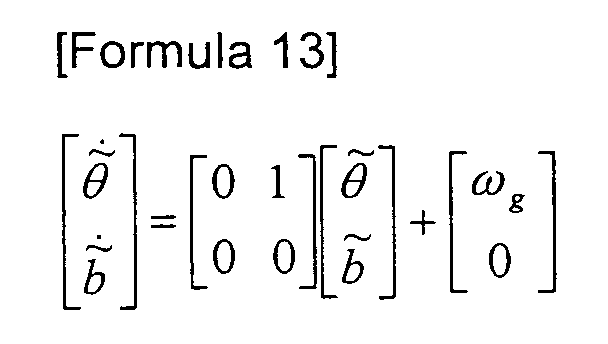
Also, when
indicates an estimated moving direction and
indicates an
estimated gyro drift rate (it is assumed that
is a constant number), an output of
a gyro estimation model, i.e., an integrator, can be represented as shown in
Formula 13.
-
Modeling of an error status is performed as follows. First, the error status
is defined as shown in Formula 14.
-
When
m indicates a measured moving direction and
v indicates
Gaussian white noise having distribution σ
v , an external sensor measurement
model can be represented as shown in Formula 15. Here, an external sensor
measurement input is selected with one of the compass final azimuth angle and
the odometer angular velocity according to the method described above.
-
An error status model is obtained as shown in Formula 16 by subtracting
Formula 12 from Formula 13.
-
FIG. 11 shows an error status measurement model.
-
The above model can be represented as a discrete model as follows. A
discrete error status can be defined as shown in Formula 17.
-
A discrete form of Formula 12 can be represented as shown in Formula 18.
-
A discrete form of Formula 13 can be represented as shown in Formula 19.
-
Formula 20 can be derived from Formulas 18 and 19.
-
A discrete form of Formula 15 can be represented as shown in Formula 21.
-
A discrete error status Kalman filter is described in detail as follows. Initial
conditions can be represented as in Formulas 22 and 23. Formula 22 represents
a Gaussian random variable (RV), whose average value is basically 0, and
Formula 23 represents distribution of the initial values and
b .
[Formula 22]
x(t 0) = [0 0] T
-
A discrete form of the Gaussian noise can be represented as shown in
Formula 24.
-
Discrete forms according to temporal updates can be represented as shown
in Formulas 25 and 26.
-
Discrete forms according to measurement updates can be represented as
shown in Formulas 27, 28 and 29.
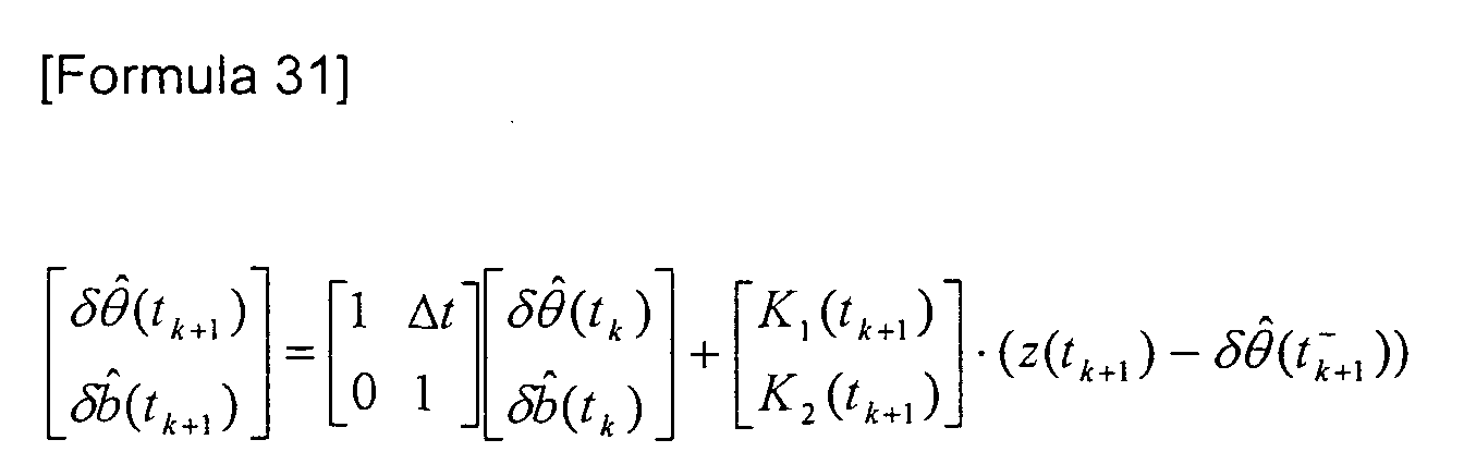
-
Formula 30 can be derived from Formula 19, and Formula 31 can be
derived from Formula 28.
-
When it is defined that and =
+ δ and,
b and =
+ δ
b and, Formula 32 can be obtained
from Formula 30 and Formula 31.
-
The initial conditions are as shown in Formula 33.
-
Formula 32 is a representative formula of the error status Kalman filter used
in an embodiment of the present invention. According to the method described
above, an optimal moving direction estimation value and(tk+ 1) can be obtained by
selecting one of the compass azimuth angle and the odometer angular velocity as
the measurement input and substituting the measurement input for m of Formula
32.
-
The invention can be embodied as computer readable codes on a computer
(including all apparatuses having a information processing function) readable
recording medium. The computer readable recording medium is any data
storage device that can store data which can be thereafter read by a computer
system. Examples of the computer readable recording medium include read-only
memory (ROM), random-access memory (RAM), CD-ROMs, magnetic tapes,
floppy disks, optical data storage devices.
-
As described above, in a sensor fusion method according to an embodiment
of the present invention, sensors with a high specification are not necessary.
Accordingly, a high performance can be realized with low-price sensors. Also,
various unexpected situations that can be dealt with when a mobile body is moved
and various kinds of error sources can be estimated. Furthermore, various
typical limits included in the Kalman filter, such as that exact information of error
characteristics of the sensors is not necessary and that bias, colored noise, and
nonsystematic errors can be dealt with, can be overcome. As an ancillary effect,
a system fault sensing function can be realized.
-
Since 3-dimensional angle information is robustly provided by effectively
obtaining a yaw angle according to an embodiment of the present invention, the
present invention can be applied to all fields requiring estimation of an absolute
position and orientation. The applicable fields are as follows: autonomic traveling
vehicles, intelligent vehicles, car navigation, medical robots, virtual reality,
entertainment, unmanned planes, and personal navigation.
-
While the present invention has been particularly shown and described with
reference to exemplary embodiments thereof, it will be understood by those of
ordinary skill in the art that various changes in form and details may be made
therein without departing from the spirit and scope of the present invention as
defined by.the following claims.


 indicates an estimated gyro drift rate (it is assumed that