EP1527791A2 - Fluid suction device - Google Patents
Fluid suction device Download PDFInfo
- Publication number
- EP1527791A2 EP1527791A2 EP05002552A EP05002552A EP1527791A2 EP 1527791 A2 EP1527791 A2 EP 1527791A2 EP 05002552 A EP05002552 A EP 05002552A EP 05002552 A EP05002552 A EP 05002552A EP 1527791 A2 EP1527791 A2 EP 1527791A2
- Authority
- EP
- European Patent Office
- Prior art keywords
- bag
- connection
- disposable bag
- suction
- disposable
- Prior art date
- Legal status (The legal status is an assumption and is not a legal conclusion. Google has not performed a legal analysis and makes no representation as to the accuracy of the status listed.)
- Granted
Links
Images
Classifications
-
- A—HUMAN NECESSITIES
- A61—MEDICAL OR VETERINARY SCIENCE; HYGIENE
- A61M—DEVICES FOR INTRODUCING MEDIA INTO, OR ONTO, THE BODY; DEVICES FOR TRANSDUCING BODY MEDIA OR FOR TAKING MEDIA FROM THE BODY; DEVICES FOR PRODUCING OR ENDING SLEEP OR STUPOR
- A61M1/00—Suction or pumping devices for medical purposes; Devices for carrying-off, for treatment of, or for carrying-over, body-liquids; Drainage systems
- A61M1/60—Containers for suction drainage, adapted to be used with an external suction source
- A61M1/604—Bag or liner in a rigid container, with suction applied to both
-
- A—HUMAN NECESSITIES
- A61—MEDICAL OR VETERINARY SCIENCE; HYGIENE
- A61M—DEVICES FOR INTRODUCING MEDIA INTO, OR ONTO, THE BODY; DEVICES FOR TRANSDUCING BODY MEDIA OR FOR TAKING MEDIA FROM THE BODY; DEVICES FOR PRODUCING OR ENDING SLEEP OR STUPOR
- A61M1/00—Suction or pumping devices for medical purposes; Devices for carrying-off, for treatment of, or for carrying-over, body-liquids; Drainage systems
- A61M1/71—Suction drainage systems
- A61M1/78—Means for preventing overflow or contamination of the pumping systems
- A61M1/784—Means for preventing overflow or contamination of the pumping systems by filtering, sterilising or disinfecting the exhaust air, e.g. swellable filter valves
-
- A—HUMAN NECESSITIES
- A61—MEDICAL OR VETERINARY SCIENCE; HYGIENE
- A61M—DEVICES FOR INTRODUCING MEDIA INTO, OR ONTO, THE BODY; DEVICES FOR TRANSDUCING BODY MEDIA OR FOR TAKING MEDIA FROM THE BODY; DEVICES FOR PRODUCING OR ENDING SLEEP OR STUPOR
- A61M2205/00—General characteristics of the apparatus
- A61M2205/75—General characteristics of the apparatus with filters
- A61M2205/7536—General characteristics of the apparatus with filters allowing gas passage, but preventing liquid passage, e.g. liquophobic, hydrophobic, water-repellent membranes
Abstract
Description
Die vorliegende Erfindung betrifft einen Einwegbeutel zum Absaugen von Flüssigkeiten,
insbesondere von Körperflüssigkeiten im Rahmen medizinischer Behandlungen,
gemäss Oberbegriff des Patentanspruchs 1.The present invention relates to a disposable bag for aspirating liquids,
in particular of body fluids in the context of medical treatments,
according to the preamble of
Im medizinischen Bereich sind für das Absaugen von Körperflüssigkeiten heute die verschiedensten Systeme bzw. Methoden bekannt. In all jenen Fällen, wo die Körperflüssigkeiten durch Anwendung von Unterdruck abzusaugen und aufzufangen sind, kann dies z.B. dadurch geschehen, dass ein Auffangbehälter aus starrem Material mit einem Deckel versehen wird, in welchen einerseits die Absaugleitung führt und andererseits ein Anschluss zum Aufbau eines Unterdruckes vorgesehen ist, wobei dieser Anschluss zu einer Saugquelle (Saugpumpe) führt. Das Problem bei diesem System liegt darin, dass zur Entsorgung der aufgefangenen Flüssigkeiten der Behälter als Ganzes zu transportieren ist und nach dem Entleeren des Inhaltes einer sorgfältigen Reinigung zu unterziehen ist. Dieses System entspricht nach neuesten Erkenntnissen in gewissen Fällen den Anforderungen an die Hygiene nicht mehr. Um dieses Problem zu lösen, wurde vorgeschlagen, im Innern des starren Behälters einen Einwegbeutel unterzubringen, welcher allein zum Auffangen der abzusaugenden Flüssigkeiten dient. Ein solcherart mit Flüssigkeit gefüllter Beutel kann zur Entsorgung nach Abnehmen des Behälterdeckels entfernt und der eigentlichen Entsorgung zugeführt werden, während der starre Behälter in der Regel bereits mit einem neuen Beutel ausgerüstet werden kann. Das Problem bei diesem System liegt darin, dass zwei verschiedene Unterdruck-Leitungen (Vakuum-Leitungen) erforderlich sind, nämlich die eine, um den Beutel aufzuweiten und diesen gegen die Behälter-Innenwand anzulegen, und ein zweiter Anschluss, welcher ins Beutelinnere führt, um nach dessen Aufweitung im Beutelinnern den erforderlichen Unterdruck zu erzeugen. Dabei ist immer darauf zu achten, dass der Unterdruck im den Beutel umgebenden Raum höher sein muss als jener im Innern des Beutels, da sonst die Gefahr besteht, dass der Beutel wieder zusammenklappt und eine weitere Füllung nicht mehr möglich ist. Ganz abgesehen davon, ist eine solche Konstruktion aufwendig und somit teuer. In the medical field are for the suction of body fluids today various systems or methods known. In all those cases where the body fluids be sucked off and absorbed by applying negative pressure, This can e.g. be done by a collecting container made of rigid material with a lid is provided, in which on the one hand leads the suction and on the other a connection is provided for establishing a negative pressure, wherein this connection leads to a suction source (suction pump). The problem with this system lies in that for disposal of the collected liquids the container as a whole too transport and after emptying the contents of a careful cleaning too undergo. This system corresponds to the latest findings in certain cases no longer meet the hygiene requirements. To solve this problem was proposed to accommodate a disposable bag inside the rigid container, which alone serves to catch the liquids to be sucked off. Such a way bag filled with liquid may be disposed of after removal of the container lid removed and the actual disposal be fed while the rigid Container can usually already be equipped with a new bag. The Problem with this system is that two different vacuum lines (Vacuum lines) are required, namely the one to widen the bag and to apply this against the container inner wall, and a second terminal, which leads into the bag interior, after the expansion in the bag inside the required Create negative pressure. It is always important to ensure that the negative pressure in The bag surrounding space must be higher than the one inside the bag, otherwise there is a risk that the bag collapses again and another filling is no longer possible. Quite apart from that, such a construction is expensive and therefore expensive.
Aufgabe der vorliegenden Erfindung war es somit, einen Einwegbeutel zu schaffen, mit welchem bei einfachster Konstruktion das Auffangen von Flüssigkeiten problemlos möglich ist.Object of the present invention was thus to provide a disposable bag, with which in the simplest design, the collection of liquids easily is possible.
Diese Aufgabe wird erfindungsgemäss durch einen Einwegbeutel mit den Merkmalen
gemäss Anspruch 1 gelöst.This object is achieved by a disposable bag with the features
solved according to
Dank der erfindungsgemässen Konstruktion wird es mit einer einzigen Unterdruckleitung möglich, zuerst den flexiblen Behälter im Innern des luftdicht abgeschlossenen Auffangbehälters aufzuweiten und in dieser Stellung zu halten und erst nach dem Aufweiten die Saugwirkung ins Innere des Beutels zu verlegen. Beim aufgeweiteten Beutel, welcher durch den angelegten Unterdruck immer in diesem erforderlichen Zustand gehalten wird, sorgt die gasdurchlässige Membran dafür, dass durch diese keine Flüssigkeit austreten kann (Sperrmembran), jedoch Luft zwecks Erzeugung des erforderten Unterdruckes abgesaugt werden kann. Durch diese einfache Massnahme, welche sich durch das starre Kopfteil am Beutel realisieren lässt, entsteht eine ausserordentlich einfach aufgebaute Einrichtung. Das ausbrechbare Element verschliesst im Normalfall eine Durchgangsöffnung. Diese Öffnung kann beim Entleeren des Beutels als Entlüftung dienen.Thanks to the inventive construction, it is with a single vacuum line possible, first the flexible container inside the hermetically sealed To widen the collection container and keep in this position and only after the expansion to move the suction into the interior of the bag. With the expanded bag, which by the applied negative pressure always in this required state held, the gas-permeable membrane ensures that through this no liquid can exit (barrier membrane), however, air for the purpose of generating the required Vacuum can be sucked. Through this simple measure, which itself can be realized by the rigid headboard on the bag, creates an extremely simple built-up device. The break-out element normally closes one Through opening. This opening can be used as a vent when emptying the bag serve.
Besondere Ausführungsformen sind in den abhängigen Ansprüchen definiert.Particular embodiments are defined in the dependent claims.
Es sei nochmals wiederholt, dass beim Einsatz von Einwegbeuteln dafür Sorge getragen werden muss, dass beim Eintritt der Saugwirkung die Beutelwände nicht einfach zusammenklappen, sondern dass der Beutel zuerst in Richtung der Wand des starren Auffangbehälters aufgeweitet bzw. gegen die Behälterwände angelegt werden muss. Das war bisher nur unter Einrichtung von zwei verschiedenen Vakuumleitungen möglich, wobei die eine zum Aufweiten des Beutels diente, die andere zum Erzeugen des Vakuums im Beutelinnem. Nachteilig an diesem System war einerseits der komplexe Aufbau, und zudem konnte die Wirkung nicht immer gewährleistet werden, ohne die Einrichtung nochmals zu komplizieren. It should be repeated again that the use of disposable bags made sure must be that the bag walls do not fold when the suction effect occurs, but that the bag first towards the wall of the rigid collection container must be expanded or created against the container walls. The was previously only possible with the installation of two different vacuum lines, one for widening the bag, the other for creating the vacuum in the bag interior. A disadvantage of this system was on the one hand the complex structure, And moreover, the effect could not always be guaranteed without the device to complicate again.
Die Erfindung wird anschliessend anhand eines in der Zeichnung dargestellten Ausführungsbeispiels noch etwas näher erläutert. Es zeigen:
- Fig. 1
- Einen Vertikalschnitt durch einen starren Auffangbehälter, in welchen ein flexibler Einwegbeutel mit starrem Kopfteil eingesetzt ist;
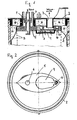
- Fig. 2
- rein schematisch eine Ansicht von unten auf die Unterseite des Behälter-Deckels mit eingesetztem Einwegbeutel und
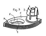
- Fig. 3
- eine perspektivische Ansicht des starren Kopfteils eines Einwegbeutels gemäss Fig. 1.
- Fig. 1
- A vertical section through a rigid collecting container, in which a flexible disposable bag is used with a rigid head part;
- Fig. 2
- purely schematically a view from below of the underside of the container lid with inserted disposable bag and
- Fig. 3
- a perspective view of the rigid head portion of a disposable bag according to FIG. 1.
Figur 1 der Zeichnung zeigt rein schematisch eine Einrichtung nach der Erfindung. Dabei
ist auf einen starren Behälter 1 ein Deckel 2 so aufgesetzt, dass ein luftdichter Verschluss
entsteht. Dies wird durch entsprechende Dichtungen zwischen Behälter 1 und
Deckel 2 realisiert. Im Deckel 2 selbst ist eine Anschlussöffnung 3 für den Anschluss
einer Verbindungsleitung zu einer Saugquelle (Saugpumpe, nicht dargestellt) vorgesehen,
in welche die Verbindungsleitung ebenfalls luftdicht einsteckbar oder anderweitig
anschliessbar ist. Der Behälterdeckel 2 weist ferner eine Anschlussöffnung 4 zum Anbringen
einer zum Patienten führenden Absaugleitung auf (nicht dargestellt).Figure 1 of the drawing shows purely schematically a device according to the invention. In this case, a
Wie die Zeichnung zeigt, ist von der Unterseite des Behälterdeckels her ein starres
Kopfteil 5 eines flexiblen Einwegbeutels B befestigt. Das starre Kopfteil 5 besteht aus
einer schiffchenförmigen Platte, von welcher einerseits ein Anschlussnippel 6 durch die
Behälterdeckel-Öffnung 4 nach oben führt und welche von federnden Rastklinken 7
umgeben ist. Der Nippel 6 dient zum Aufstecken der zum Patienten führenden Absaugleitung.
Zwischen der Kopfplatte 5 des Beutels B und dem Behälterdeckel 2 ist eine
Dichtung vorgesehen, um die Verbindung luftdicht zu gestalten. Die Rastklinken 7 lassen
sich durch die Deckelöffnung 4 hindurchführen und spreizen dann in die Halteposition
aus, wie dies aus Fig. 1 hervorgeht. Damit ist die starre Platte 5 des Einwegbeutels
fest auf der Unterseite des Deckels angebracht. Bei angeschlossener Absaugleitung und
Verbindungsleitung zur Saugquelle ist klar ersichtlich, dass der Innenraum des Behälters
1 gegenüber der Umgebung völlig abgedichtet ist.As the drawing shows, is from the bottom of the container lid ago a
In der Kopfplatte 5 des Beutels ist eine weitere Öffnung 8 vorgesehen, in welcher eine
Membran 9 festgehalten ist. Diese Membran 9 ist bezüglich Flüssigkeiten undurchlässig,
jedoch unter Überwindung eines geringen Widerstandes für Gas bzw. Luft durchlässig.In the
In der Kopfplatte 5 des Beutels B ist eine weitere Durchgangsöffnung 10 vorgesehen,
welche im Normalfall durch ein ausbrechbares Element 11 verschlossen ist. Diese Öffnung
könnte dazu dienen, bei Entleerung eines Beutels B als Entlüftung zu dienen, um
das Ausströmen der aufgefangenen Flüssigkeit durch den Nippel 6 hindurch zu erleichtert,
falls dies notwendig wäre. In der Regel wird allerdings eine Entleerung durch
Druck auf die Beutelwand ausreichen.In the
Zur allgemeinen Illustration zeigt Fig. 3 noch eine perspektivische Darstellung des starren
Kopfteils 5 eines Einwegbeutels B.For general illustration Fig. 3 shows a perspective view of the
Wenn nun nach auf der Unterseite des Deckels 2 angebrachtem Beutel (mit im Deckel
festgehaltener bzw. festgeklemmter Kopfplatte 5 des Beutels B, angeschlossener, zur
Vakuumquelle führender Leitung und angeschlossener Patientenleitung) die Vakuumquelle
in Betrieb genommen wird, d.h. durch den Anschluss hindurch eine Saugwirkung
erzeugt wird, wird zuerst am oberen Ende des Behälters, in den Räumen A die Luft
evakuiert und damit der Beutel B mit seinen Seitenwänden in Richtung zu den Behälterwänden
1 aufgeweitet bzw. an diese angelegt, danach wird auch die Luft durch die
Membrane 9 hindurch im Beutelinnern abgesaugt und dabei ein Unterdruck erzeugt,
welcher wiederum dafür sorgt, dass die abzusaugende Flüssigkeit über den Patientenanschluss
ins Innere des Beutels B gelangt.If now after on the bottom of the
Durch die einfache Konstruktion, insbesondere des starren Kopfteils 5 des Einwegbeutels,
ist eine Einrichtung geschaffen, welche mit einem minimalen Konstruktionsaufwand
das Absaugen von Flüssigkeiten in einen Einwegbeutel ermöglicht. Gleichzeitig
eignet sich diese Einrichtung auch für den normalen Einsatz, d.h. das Absaugen von
Flüssigkeiten direkt in den starren Behälter 1. Dazu kann entweder derselbe Deckel 2
verwendet werden oder aber ein separater Deckel vorgesehen sein, welcher einen Anschluss
für eine Absaugleitung und einen Anschluss für eine Vakuumquelle aufweist.Due to the simple construction, in particular of the
Claims (5)
Priority Applications (1)
| Application Number | Priority Date | Filing Date | Title |
|---|---|---|---|
| EP05002552A EP1527791B1 (en) | 1997-02-26 | 1997-02-26 | Fluid suction device |
Applications Claiming Priority (2)
| Application Number | Priority Date | Filing Date | Title |
|---|---|---|---|
| EP05002552A EP1527791B1 (en) | 1997-02-26 | 1997-02-26 | Fluid suction device |
| EP97103068A EP0861668B1 (en) | 1997-02-26 | 1997-02-26 | Fluid suction device |
Related Parent Applications (1)
| Application Number | Title | Priority Date | Filing Date |
|---|---|---|---|
| EP97103068A Division EP0861668B1 (en) | 1997-02-26 | 1997-02-26 | Fluid suction device |
Publications (3)
| Publication Number | Publication Date |
|---|---|
| EP1527791A2 true EP1527791A2 (en) | 2005-05-04 |
| EP1527791A3 EP1527791A3 (en) | 2005-07-27 |
| EP1527791B1 EP1527791B1 (en) | 2007-09-26 |
Family
ID=8226523
Family Applications (2)
| Application Number | Title | Priority Date | Filing Date |
|---|---|---|---|
| EP97103068A Expired - Lifetime EP0861668B1 (en) | 1997-02-26 | 1997-02-26 | Fluid suction device |
| EP05002552A Expired - Lifetime EP1527791B1 (en) | 1997-02-26 | 1997-02-26 | Fluid suction device |
Family Applications Before (1)
| Application Number | Title | Priority Date | Filing Date |
|---|---|---|---|
| EP97103068A Expired - Lifetime EP0861668B1 (en) | 1997-02-26 | 1997-02-26 | Fluid suction device |
Country Status (7)
| Country | Link |
|---|---|
| US (1) | US6056730A (en) |
| EP (2) | EP0861668B1 (en) |
| JP (1) | JP2920825B2 (en) |
| AT (2) | ATE374052T1 (en) |
| CA (1) | CA2229495C (en) |
| DE (2) | DE59712133D1 (en) |
| ES (2) | ES2294581T3 (en) |
Families Citing this family (53)
| Publication number | Priority date | Publication date | Assignee | Title |
|---|---|---|---|---|
| US6458109B1 (en) | 1998-08-07 | 2002-10-01 | Hill-Rom Services, Inc. | Wound treatment apparatus |
| US6824533B2 (en) | 2000-11-29 | 2004-11-30 | Hill-Rom Services, Inc. | Wound treatment apparatus |
| US6764462B2 (en) | 2000-11-29 | 2004-07-20 | Hill-Rom Services Inc. | Wound treatment apparatus |
| WO2001049344A1 (en) * | 1999-12-31 | 2001-07-12 | Oy Nikomed Finland Ab | Suction bag device |
| JP2004509658A (en) | 2000-05-22 | 2004-04-02 | コフィー,アーサー,シー. | Combination of small intestinal submucosa and vacuum bandage and its use |
| US6685681B2 (en) | 2000-11-29 | 2004-02-03 | Hill-Rom Services, Inc. | Vacuum therapy and cleansing dressing for wounds |
| US6855135B2 (en) | 2000-11-29 | 2005-02-15 | Hill-Rom Services, Inc. | Vacuum therapy and cleansing dressing for wounds |
| EP1450878A1 (en) | 2001-10-11 | 2004-09-01 | Hill-Rom Services, Inc. | Waste container for negative pressure therapy |
| US7534927B2 (en) | 2001-12-26 | 2009-05-19 | Hill-Rom Services, Inc. | Vacuum bandage packing |
| EP1478313B2 (en) | 2001-12-26 | 2018-03-07 | KCI Medical Resources | Vented vacuum bandage |
| WO2003057307A1 (en) | 2001-12-26 | 2003-07-17 | Hill-Rom Services, Inc. | Wound vacuum therapy dressing kit |
| US20040024352A1 (en) * | 2001-12-27 | 2004-02-05 | Playtex Products, Inc. | Breast pump system |
| CA2471208C (en) * | 2001-12-27 | 2010-03-23 | Playtex Products, Inc. | Breast cup |
| CA2477674A1 (en) * | 2002-02-28 | 2003-09-12 | Jeffrey S. Lockwood | External catheter access to vacuum bandage |
| US8168848B2 (en) | 2002-04-10 | 2012-05-01 | KCI Medical Resources, Inc. | Access openings in vacuum bandage |
| US7896856B2 (en) | 2002-08-21 | 2011-03-01 | Robert Petrosenko | Wound packing for preventing wound closure |
| US7520872B2 (en) * | 2002-09-13 | 2009-04-21 | Neogen Technologies, Inc. | Closed wound drainage system |
| US6979324B2 (en) * | 2002-09-13 | 2005-12-27 | Neogen Technologies, Inc. | Closed wound drainage system |
| US20040127845A1 (en) * | 2002-12-27 | 2004-07-01 | Playtex Products, Inc. | Breast pump system |
| US7811293B2 (en) * | 2003-01-31 | 2010-10-12 | Philip J. Simpson | System and method for rapid placement of chest tubes |
| JP4411929B2 (en) * | 2003-02-28 | 2010-02-10 | 株式会社日立製作所 | Backup method, system, and program |
| US7635359B2 (en) * | 2003-06-10 | 2009-12-22 | Daiken Iki Kabushiki Kaisha | Receptacle for use with a medical suction device |
| US7776008B2 (en) * | 2003-08-08 | 2010-08-17 | Playtex Products, Inc. | Manual breast pump |
| JP2007512102A (en) | 2003-11-20 | 2007-05-17 | ザ ヘンリー エム. ジャクソン ファウンデーション フォー ザ アドヴァンスメント オブ ミリタリー メディシン, インク. | Portable manual pump for fluid suction |
| US8337475B2 (en) | 2004-10-12 | 2012-12-25 | C. R. Bard, Inc. | Corporeal drainage system |
| US7950908B2 (en) * | 2005-01-26 | 2011-05-31 | Seiko Epson Corporation | Fluid transporting device of a peristalic type with tube and push pin arrangement |
| ATE553794T1 (en) * | 2006-01-27 | 2012-05-15 | Medela Holding Ag | FASTENING DEVICE FOR DRAINAGE TANKS |
| WO2007120622A2 (en) * | 2006-04-11 | 2007-10-25 | Playtex Products, Inc | Manual breast pump |
| MX2009009807A (en) * | 2007-03-13 | 2009-09-24 | Medela Holding Ag | Vacuum diaphragm pump unit. |
| US8083712B2 (en) * | 2007-03-20 | 2011-12-27 | Neogen Technologies, Inc. | Flat-hose assembly for wound drainage system |
| EP2152334B1 (en) | 2007-05-22 | 2018-08-01 | Medela Holding AG | Drainage pump unit |
| WO2008154383A1 (en) * | 2007-06-07 | 2008-12-18 | Andrew Gadzic | Cap and liner system for a container |
| DE202008005027U1 (en) | 2008-04-11 | 2008-06-26 | Medela Holding Ag | Drainage tank with integrated attachment |
| DE202008005025U1 (en) | 2008-04-11 | 2008-06-26 | Medela Holding Ag | Fastening device for a drainage container |
| TW201023927A (en) * | 2008-12-29 | 2010-07-01 | Ind Tech Res Inst | Processing system and collecting device thereof |
| CH706565A1 (en) * | 2012-05-29 | 2013-11-29 | Medela Holding Ag | Drainage container device and Saugbeuteleinheit. |
| JP5636477B2 (en) * | 2013-08-29 | 2014-12-03 | 株式会社日立製作所 | Automatic urine collecting device |
| JP2015058212A (en) * | 2013-09-19 | 2015-03-30 | 泉工医科工業株式会社 | Sheet reservoir |
| CN104548228A (en) * | 2015-01-30 | 2015-04-29 | 苏州大学 | Drainage bag |
| US10583228B2 (en) | 2015-07-28 | 2020-03-10 | J&M Shuler Medical, Inc. | Sub-atmospheric wound therapy systems and methods |
| EP4349379A2 (en) * | 2015-10-16 | 2024-04-10 | Allegiance Corporation | Fluid collection systems |
| US10814047B2 (en) * | 2016-04-25 | 2020-10-27 | Allegiance Corporation | Fluid collection systems and methods of use |
| AU2017299466B2 (en) | 2016-07-18 | 2022-07-14 | Merit Medical Systems, Inc. | Inflatable radial artery compression device |
| GB201718647D0 (en) * | 2017-11-10 | 2017-12-27 | Teleflex Life Sciences Unlimited Co | Medical container |
| ES2952967T3 (en) | 2017-11-17 | 2023-11-07 | Hollister Inc | Containers that have tear control features |
| FI129046B (en) * | 2019-03-29 | 2021-05-31 | Serres Oy | Suction bag for medical or surgical use, and suction bag arrangement |
| GB2586993B (en) * | 2019-09-11 | 2021-12-01 | Keymed Medical & Industrial Equipment Ltd | Container cap |
| JP7269851B2 (en) * | 2019-09-20 | 2023-05-09 | 大研医器株式会社 | Waste liquid storage container, waste liquid reservoir provided with the same, and waste liquid suction system |
| US11160917B2 (en) | 2020-01-22 | 2021-11-02 | J&M Shuler Medical Inc. | Negative pressure wound therapy barrier |
| US11318476B2 (en) | 2020-04-30 | 2022-05-03 | Mss, Inc. | Separation of ferrous materials |
| US20220080097A1 (en) * | 2020-09-14 | 2022-03-17 | Merit Medical Systems, Inc. | Vacuum drainage collection bottle |
| USD977671S1 (en) | 2021-03-31 | 2023-02-07 | Merit Medical Systems, Inc. | Vacuum drainage storage bottle |
| KR102459954B1 (en) * | 2022-02-07 | 2022-10-31 | 주식회사 큐라코 | Dual-structured separable waste accommodating module |
Citations (5)
| Publication number | Priority date | Publication date | Assignee | Title |
|---|---|---|---|---|
| US3680560A (en) * | 1968-11-26 | 1972-08-01 | Voys Inc Le | Vacuum drainage collecting apparatus with disposable liner |
| US4306557A (en) * | 1978-08-29 | 1981-12-22 | North Daniel A | Vacuum urological surgical irrigating solution collecting system |
| US4821896A (en) * | 1988-03-24 | 1989-04-18 | Cheng Ping N | Nursing bottle with a liner and vent |
| EP0378296A2 (en) * | 1989-01-12 | 1990-07-18 | Smiths Industries Public Limited Company | Suction pump assemblies |
| WO1994014045A1 (en) * | 1992-12-15 | 1994-06-23 | Langdon Medical, Inc. | An apparatus for collecting a fluid sample from a patient and container for storing the same |
Family Cites Families (12)
| Publication number | Priority date | Publication date | Assignee | Title |
|---|---|---|---|---|
| US3669815A (en) * | 1971-02-10 | 1972-06-13 | Balsa Dev Corp | Structural light-weight panel for cryogenic and elevated temperature applications |
| US4063556A (en) * | 1976-04-14 | 1977-12-20 | Ryder International Corporation | Vacuum curettage device |
| US4419903A (en) * | 1982-02-22 | 1983-12-13 | Beckman Instruments, Inc. | Method and apparatus for detecting insufficient liquid levels |
| DE3500538A1 (en) * | 1985-01-10 | 1986-07-17 | Aesculap-Werke Ag Vormals Jetter & Scheerer, 7200 Tuttlingen | Bag for reception of discharge |
| US4772256A (en) * | 1986-11-07 | 1988-09-20 | Lantech, Inc. | Methods and apparatus for autotransfusion of blood |
| FR2632907B1 (en) * | 1988-06-20 | 1992-02-21 | Peugeot | GLOVE BOX OR OTHER RECEPTACLE HAVING AN ARTICULATED LID |
| US5002534A (en) * | 1988-06-22 | 1991-03-26 | Rosenblatt/Ima Invention Enterprises | Aspirator without partition wall for collection of bodily fluids including improved safety and efficiency elements |
| US4870975A (en) * | 1988-07-05 | 1989-10-03 | Scott Cronk | Suction canister assembly for the collection of body fluids and tissue specimens |
| CH686027A5 (en) * | 1991-07-26 | 1995-12-15 | Elp Rochat | Unit of recovery and blood filtration. |
| US5470324A (en) * | 1993-07-01 | 1995-11-28 | Baxter International Inc. | Non-refluxing suction canister system and components therefor |
| US5713879A (en) * | 1994-02-26 | 1998-02-03 | Metec A. Schneider Gmbh | Device for collecting and filtering blood |
| FR2716806B1 (en) * | 1994-03-01 | 1996-05-24 | Technologie Medicale | Device for recovering liquid residues, in particular organic residues intended for disposal. |
-
1997
- 1997-02-26 AT AT05002552T patent/ATE374052T1/en not_active IP Right Cessation
- 1997-02-26 DE DE59712133T patent/DE59712133D1/en not_active Expired - Lifetime
- 1997-02-26 AT AT97103068T patent/ATE288769T1/en not_active IP Right Cessation
- 1997-02-26 ES ES05002552T patent/ES2294581T3/en not_active Expired - Lifetime
- 1997-02-26 EP EP97103068A patent/EP0861668B1/en not_active Expired - Lifetime
- 1997-02-26 DE DE59712885T patent/DE59712885D1/en not_active Expired - Lifetime
- 1997-02-26 EP EP05002552A patent/EP1527791B1/en not_active Expired - Lifetime
- 1997-02-26 ES ES97103068T patent/ES2236764T3/en not_active Expired - Lifetime
-
1998
- 1998-02-06 US US09/019,952 patent/US6056730A/en not_active Expired - Lifetime
- 1998-02-10 CA CA002229495A patent/CA2229495C/en not_active Expired - Fee Related
- 1998-02-20 JP JP10038652A patent/JP2920825B2/en not_active Expired - Fee Related
Patent Citations (5)
| Publication number | Priority date | Publication date | Assignee | Title |
|---|---|---|---|---|
| US3680560A (en) * | 1968-11-26 | 1972-08-01 | Voys Inc Le | Vacuum drainage collecting apparatus with disposable liner |
| US4306557A (en) * | 1978-08-29 | 1981-12-22 | North Daniel A | Vacuum urological surgical irrigating solution collecting system |
| US4821896A (en) * | 1988-03-24 | 1989-04-18 | Cheng Ping N | Nursing bottle with a liner and vent |
| EP0378296A2 (en) * | 1989-01-12 | 1990-07-18 | Smiths Industries Public Limited Company | Suction pump assemblies |
| WO1994014045A1 (en) * | 1992-12-15 | 1994-06-23 | Langdon Medical, Inc. | An apparatus for collecting a fluid sample from a patient and container for storing the same |
Also Published As
| Publication number | Publication date |
|---|---|
| CA2229495A1 (en) | 1998-08-26 |
| EP0861668B1 (en) | 2005-02-09 |
| ATE288769T1 (en) | 2005-02-15 |
| ATE374052T1 (en) | 2007-10-15 |
| ES2294581T3 (en) | 2008-04-01 |
| EP1527791A3 (en) | 2005-07-27 |
| EP1527791B1 (en) | 2007-09-26 |
| JP2920825B2 (en) | 1999-07-19 |
| DE59712885D1 (en) | 2007-11-08 |
| EP0861668A1 (en) | 1998-09-02 |
| CA2229495C (en) | 2002-01-29 |
| ES2236764T3 (en) | 2005-07-16 |
| US6056730A (en) | 2000-05-02 |
| DE59712133D1 (en) | 2005-01-27 |
| JPH10243998A (en) | 1998-09-14 |
Similar Documents
| Publication | Publication Date | Title |
|---|---|---|
| EP1527791B1 (en) | Fluid suction device | |
| EP2152334B1 (en) | Drainage pump unit | |
| EP2536448B1 (en) | Coupling part for a drainage tube unit | |
| DE2824588C2 (en) | Closing device for a vacuum tube for taking blood | |
| EP0082510B1 (en) | Medical suction bottle | |
| EP2854891B1 (en) | Drainage container device and a suction pouch unit | |
| DE2439392A1 (en) | DEVICE AND METHOD FOR ASEPTIC COLLECTION OF FLUIDS BY VACUUM PRESSURE | |
| EP0882440A2 (en) | Suction device for body fluids | |
| CH646334A5 (en) | DEVICE FOR REMOVING FLUIDS FROM A Wound. | |
| DE1491739B1 (en) | Device for draining fluids from body cavities | |
| WO1995024230A1 (en) | Device for closing wounds by vacuum and/or for extracting secretion or the like | |
| DE2005541A1 (en) | Feeding bottle for medical purposes | |
| DE2106631C3 (en) | Secretion bottle | |
| DE202016100154U1 (en) | System for drainage of fluids or wound secretions | |
| DE102005060290B3 (en) | Stiff, one-time haemodialysis salt container has sealing foil bridging ventilation opening that breaks on reaching defined pressure difference between air pressure outside container, reduced pressure inside produced by dialysis device | |
| DE69823453T2 (en) | Device for taking body fluids and transferring them to sample tubes | |
| DE19537271C2 (en) | Reservoir for a closed blood collection system | |
| DE3000322C2 (en) | Device for evacuating fluids from a wound | |
| WO1984002078A1 (en) | Device for sucking and removing medical liquids | |
| EP0669139A1 (en) | Device for recovering and coarse filtration of blood from an operating theatre | |
| DE3500538A1 (en) | Bag for reception of discharge | |
| EP1725196B1 (en) | Drainage sac | |
| EP3789051B1 (en) | Capture assembly for receiving siphoned secretion comprising a liquid filter and a pathogen filter | |
| WO2012136371A1 (en) | Dialysis container made of plastic | |
| WO2021023480A1 (en) | Arrangement and method for collecting suctioned secretions, comprising a non-return valve |
Legal Events
| Date | Code | Title | Description |
|---|---|---|---|
| PUAI | Public reference made under article 153(3) epc to a published international application that has entered the european phase |
Free format text: ORIGINAL CODE: 0009012 |
|
| AC | Divisional application: reference to earlier application |
Ref document number: 0861668 Country of ref document: EP Kind code of ref document: P |
|
| AK | Designated contracting states |
Kind code of ref document: A2 Designated state(s): AT CH DE ES FR GB IT LI NL SE |
|
| PUAL | Search report despatched |
Free format text: ORIGINAL CODE: 0009013 |
|
| AK | Designated contracting states |
Kind code of ref document: A3 Designated state(s): AT CH DE ES FR GB IT LI NL SE |
|
| 17P | Request for examination filed |
Effective date: 20050830 |
|
| REG | Reference to a national code |
Ref country code: HK Ref legal event code: DE Ref document number: 1077527 Country of ref document: HK |
|
| AKX | Designation fees paid |
Designated state(s): AT CH DE ES FR GB IT LI NL SE |
|
| GRAP | Despatch of communication of intention to grant a patent |
Free format text: ORIGINAL CODE: EPIDOSNIGR1 |
|
| GRAS | Grant fee paid |
Free format text: ORIGINAL CODE: EPIDOSNIGR3 |
|
| GRAA | (expected) grant |
Free format text: ORIGINAL CODE: 0009210 |
|
| RAP1 | Party data changed (applicant data changed or rights of an application transferred) |
Owner name: MEDELA HOLDING AG |
|
| AC | Divisional application: reference to earlier application |
Ref document number: 0861668 Country of ref document: EP Kind code of ref document: P |
|
| AK | Designated contracting states |
Kind code of ref document: B1 Designated state(s): AT CH DE ES FR GB IT LI NL SE |
|
| REG | Reference to a national code |
Ref country code: GB Ref legal event code: FG4D Free format text: NOT ENGLISH |
|
| REG | Reference to a national code |
Ref country code: CH Ref legal event code: EP |
|
| REG | Reference to a national code |
Ref country code: CH Ref legal event code: NV Representative=s name: ISLER & PEDRAZZINI AG |
|
| REF | Corresponds to: |
Ref document number: 59712885 Country of ref document: DE Date of ref document: 20071108 Kind code of ref document: P |
|
| GBT | Gb: translation of ep patent filed (gb section 77(6)(a)/1977) |
Effective date: 20071106 |
|
| REG | Reference to a national code |
Ref country code: SE Ref legal event code: TRGR |
|
| REG | Reference to a national code |
Ref country code: ES Ref legal event code: FG2A Ref document number: 2294581 Country of ref document: ES Kind code of ref document: T3 |
|
| ET | Fr: translation filed | ||
| PLBE | No opposition filed within time limit |
Free format text: ORIGINAL CODE: 0009261 |
|
| STAA | Information on the status of an ep patent application or granted ep patent |
Free format text: STATUS: NO OPPOSITION FILED WITHIN TIME LIMIT |
|
| REG | Reference to a national code |
Ref country code: HK Ref legal event code: GR Ref document number: 1077527 Country of ref document: HK |
|
| 26N | No opposition filed |
Effective date: 20080627 |
|
| PGFP | Annual fee paid to national office [announced via postgrant information from national office to epo] |
Ref country code: CH Payment date: 20091217 Year of fee payment: 14 |
|
| PGFP | Annual fee paid to national office [announced via postgrant information from national office to epo] |
Ref country code: ES Payment date: 20100224 Year of fee payment: 14 |
|
| PGFP | Annual fee paid to national office [announced via postgrant information from national office to epo] |
Ref country code: FR Payment date: 20100226 Year of fee payment: 14 Ref country code: IT Payment date: 20100225 Year of fee payment: 14 |
|
| PGFP | Annual fee paid to national office [announced via postgrant information from national office to epo] |
Ref country code: AT Payment date: 20100212 Year of fee payment: 14 Ref country code: GB Payment date: 20100218 Year of fee payment: 14 Ref country code: DE Payment date: 20100219 Year of fee payment: 14 |
|
| PGFP | Annual fee paid to national office [announced via postgrant information from national office to epo] |
Ref country code: NL Payment date: 20100215 Year of fee payment: 14 |
|
| PGFP | Annual fee paid to national office [announced via postgrant information from national office to epo] |
Ref country code: SE Payment date: 20100212 Year of fee payment: 14 |
|
| REG | Reference to a national code |
Ref country code: NL Ref legal event code: V1 Effective date: 20110901 |
|
| REG | Reference to a national code |
Ref country code: CH Ref legal event code: PL |
|
| REG | Reference to a national code |
Ref country code: SE Ref legal event code: EUG |
|
| GBPC | Gb: european patent ceased through non-payment of renewal fee |
Effective date: 20110226 |
|
| PG25 | Lapsed in a contracting state [announced via postgrant information from national office to epo] |
Ref country code: CH Free format text: LAPSE BECAUSE OF NON-PAYMENT OF DUE FEES Effective date: 20110228 Ref country code: LI Free format text: LAPSE BECAUSE OF NON-PAYMENT OF DUE FEES Effective date: 20110228 |
|
| REG | Reference to a national code |
Ref country code: FR Ref legal event code: ST Effective date: 20111102 |
|
| PG25 | Lapsed in a contracting state [announced via postgrant information from national office to epo] |
Ref country code: AT Free format text: LAPSE BECAUSE OF NON-PAYMENT OF DUE FEES Effective date: 20110226 |
|
| PG25 | Lapsed in a contracting state [announced via postgrant information from national office to epo] |
Ref country code: NL Free format text: LAPSE BECAUSE OF NON-PAYMENT OF DUE FEES Effective date: 20110901 Ref country code: IT Free format text: LAPSE BECAUSE OF NON-PAYMENT OF DUE FEES Effective date: 20110226 |
|
| REG | Reference to a national code |
Ref country code: DE Ref legal event code: R119 Ref document number: 59712885 Country of ref document: DE Effective date: 20110901 |
|
| PG25 | Lapsed in a contracting state [announced via postgrant information from national office to epo] |
Ref country code: FR Free format text: LAPSE BECAUSE OF NON-PAYMENT OF DUE FEES Effective date: 20110228 |
|
| PG25 | Lapsed in a contracting state [announced via postgrant information from national office to epo] |
Ref country code: GB Free format text: LAPSE BECAUSE OF NON-PAYMENT OF DUE FEES Effective date: 20110226 |
|
| REG | Reference to a national code |
Ref country code: ES Ref legal event code: FD2A Effective date: 20120411 |
|
| PG25 | Lapsed in a contracting state [announced via postgrant information from national office to epo] |
Ref country code: ES Free format text: LAPSE BECAUSE OF NON-PAYMENT OF DUE FEES Effective date: 20110227 |
|
| PG25 | Lapsed in a contracting state [announced via postgrant information from national office to epo] |
Ref country code: SE Free format text: LAPSE BECAUSE OF NON-PAYMENT OF DUE FEES Effective date: 20110227 |
|
| PG25 | Lapsed in a contracting state [announced via postgrant information from national office to epo] |
Ref country code: DE Free format text: LAPSE BECAUSE OF NON-PAYMENT OF DUE FEES Effective date: 20110901 |