EP1526286A2 - Magnetically levitated pump utilizing magnetic bearings - Google Patents
Magnetically levitated pump utilizing magnetic bearings Download PDFInfo
- Publication number
- EP1526286A2 EP1526286A2 EP04025066A EP04025066A EP1526286A2 EP 1526286 A2 EP1526286 A2 EP 1526286A2 EP 04025066 A EP04025066 A EP 04025066A EP 04025066 A EP04025066 A EP 04025066A EP 1526286 A2 EP1526286 A2 EP 1526286A2
- Authority
- EP
- European Patent Office
- Prior art keywords
- impeller
- ferromagnetic body
- casing
- electro
- side ferromagnetic
- Prior art date
- Legal status (The legal status is an assumption and is not a legal conclusion. Google has not performed a legal analysis and makes no representation as to the accuracy of the status listed.)
- Granted
Links
Images


Classifications
-
- F—MECHANICAL ENGINEERING; LIGHTING; HEATING; WEAPONS; BLASTING
- F04—POSITIVE - DISPLACEMENT MACHINES FOR LIQUIDS; PUMPS FOR LIQUIDS OR ELASTIC FLUIDS
- F04D—NON-POSITIVE-DISPLACEMENT PUMPS
- F04D29/00—Details, component parts, or accessories
- F04D29/04—Shafts or bearings, or assemblies thereof
- F04D29/046—Bearings
- F04D29/048—Bearings magnetic; electromagnetic
-
- A—HUMAN NECESSITIES
- A61—MEDICAL OR VETERINARY SCIENCE; HYGIENE
- A61M—DEVICES FOR INTRODUCING MEDIA INTO, OR ONTO, THE BODY; DEVICES FOR TRANSDUCING BODY MEDIA OR FOR TAKING MEDIA FROM THE BODY; DEVICES FOR PRODUCING OR ENDING SLEEP OR STUPOR
- A61M60/00—Blood pumps; Devices for mechanical circulatory actuation; Balloon pumps for circulatory assistance
- A61M60/10—Location thereof with respect to the patient's body
- A61M60/122—Implantable pumps or pumping devices, i.e. the blood being pumped inside the patient's body
- A61M60/165—Implantable pumps or pumping devices, i.e. the blood being pumped inside the patient's body implantable in, on, or around the heart
- A61M60/178—Implantable pumps or pumping devices, i.e. the blood being pumped inside the patient's body implantable in, on, or around the heart drawing blood from a ventricle and returning the blood to the arterial system via a cannula external to the ventricle, e.g. left or right ventricular assist devices
-
- A—HUMAN NECESSITIES
- A61—MEDICAL OR VETERINARY SCIENCE; HYGIENE
- A61M—DEVICES FOR INTRODUCING MEDIA INTO, OR ONTO, THE BODY; DEVICES FOR TRANSDUCING BODY MEDIA OR FOR TAKING MEDIA FROM THE BODY; DEVICES FOR PRODUCING OR ENDING SLEEP OR STUPOR
- A61M60/00—Blood pumps; Devices for mechanical circulatory actuation; Balloon pumps for circulatory assistance
- A61M60/20—Type thereof
- A61M60/205—Non-positive displacement blood pumps
- A61M60/216—Non-positive displacement blood pumps including a rotating member acting on the blood, e.g. impeller
-
- A—HUMAN NECESSITIES
- A61—MEDICAL OR VETERINARY SCIENCE; HYGIENE
- A61M—DEVICES FOR INTRODUCING MEDIA INTO, OR ONTO, THE BODY; DEVICES FOR TRANSDUCING BODY MEDIA OR FOR TAKING MEDIA FROM THE BODY; DEVICES FOR PRODUCING OR ENDING SLEEP OR STUPOR
- A61M60/00—Blood pumps; Devices for mechanical circulatory actuation; Balloon pumps for circulatory assistance
- A61M60/40—Details relating to driving
- A61M60/403—Details relating to driving for non-positive displacement blood pumps
- A61M60/419—Details relating to driving for non-positive displacement blood pumps the force acting on the blood contacting member being permanent magnetic, e.g. from a rotating magnetic coupling between driving and driven magnets
-
- A—HUMAN NECESSITIES
- A61—MEDICAL OR VETERINARY SCIENCE; HYGIENE
- A61M—DEVICES FOR INTRODUCING MEDIA INTO, OR ONTO, THE BODY; DEVICES FOR TRANSDUCING BODY MEDIA OR FOR TAKING MEDIA FROM THE BODY; DEVICES FOR PRODUCING OR ENDING SLEEP OR STUPOR
- A61M60/00—Blood pumps; Devices for mechanical circulatory actuation; Balloon pumps for circulatory assistance
- A61M60/40—Details relating to driving
- A61M60/403—Details relating to driving for non-positive displacement blood pumps
- A61M60/422—Details relating to driving for non-positive displacement blood pumps the force acting on the blood contacting member being electromagnetic, e.g. using canned motor pumps
-
- A—HUMAN NECESSITIES
- A61—MEDICAL OR VETERINARY SCIENCE; HYGIENE
- A61M—DEVICES FOR INTRODUCING MEDIA INTO, OR ONTO, THE BODY; DEVICES FOR TRANSDUCING BODY MEDIA OR FOR TAKING MEDIA FROM THE BODY; DEVICES FOR PRODUCING OR ENDING SLEEP OR STUPOR
- A61M60/00—Blood pumps; Devices for mechanical circulatory actuation; Balloon pumps for circulatory assistance
- A61M60/80—Constructional details other than related to driving
- A61M60/802—Constructional details other than related to driving of non-positive displacement blood pumps
- A61M60/818—Bearings
- A61M60/82—Magnetic bearings
-
- F—MECHANICAL ENGINEERING; LIGHTING; HEATING; WEAPONS; BLASTING
- F04—POSITIVE - DISPLACEMENT MACHINES FOR LIQUIDS; PUMPS FOR LIQUIDS OR ELASTIC FLUIDS
- F04D—NON-POSITIVE-DISPLACEMENT PUMPS
- F04D13/00—Pumping installations or systems
- F04D13/02—Units comprising pumps and their driving means
- F04D13/06—Units comprising pumps and their driving means the pump being electrically driven
- F04D13/0666—Units comprising pumps and their driving means the pump being electrically driven the motor being of the plane gap type
-
- A—HUMAN NECESSITIES
- A61—MEDICAL OR VETERINARY SCIENCE; HYGIENE
- A61M—DEVICES FOR INTRODUCING MEDIA INTO, OR ONTO, THE BODY; DEVICES FOR TRANSDUCING BODY MEDIA OR FOR TAKING MEDIA FROM THE BODY; DEVICES FOR PRODUCING OR ENDING SLEEP OR STUPOR
- A61M60/00—Blood pumps; Devices for mechanical circulatory actuation; Balloon pumps for circulatory assistance
- A61M60/10—Location thereof with respect to the patient's body
- A61M60/122—Implantable pumps or pumping devices, i.e. the blood being pumped inside the patient's body
- A61M60/126—Implantable pumps or pumping devices, i.e. the blood being pumped inside the patient's body implantable via, into, inside, in line, branching on, or around a blood vessel
- A61M60/148—Implantable pumps or pumping devices, i.e. the blood being pumped inside the patient's body implantable via, into, inside, in line, branching on, or around a blood vessel in line with a blood vessel using resection or like techniques, e.g. permanent endovascular heart assist devices
Abstract
Description
- The present invention relates to a magnetically levitated pump and, more specifically, to a clean pump utilizing a magnetic bearing, which is used, by way of example, in a medical instrument such as an artificial heart.
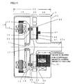
- Fig. 11 shows a magnetically levitated pump of a first prior art example having an electro-
magnet 31 for magnetic bearing and amotor 13 provided on opposite sides of an impeller 23 (see Fig. 5 of Japanese Patent Laying-Open No. 2002-130177 and Fig. 16A of U.S. Patent No. 6,626,644 B2). Referring to Fig. 11, the magnetically levitated pump of the first prior art example will be described. The magnetically levitatedpump 1 of the first prior art example is formed of amotor unit 10, apump unit 20 and amagnetic bearing unit 30. In acasing 21 ofpump unit 20, apump chamber 22 is provided. Impeller 23 rotates in thispump chamber 22.Impeller 23 has a plurality of blades, not shown. -
Casing 21 is formed of a non-magnetic material, andimpeller 23 is pivotally supported by a non-controlled magnetic bearing and a controlled magnetic bearing. The non-controlled magnetic bearing is formed of a rotor-sidepermanent magnet 14 and an impeller-sidepermanent magnet 24, while the controlled magnetic bearing is formed of an electro-magnet 31 for magnetic bearing and a softmagnetic member 27 opposite to the electro-magnet and to a position sensor. Impeller-sidepermanent magnet 24 is divided along the circumferential direction ofimpeller 23, and adjacent magnets are magnetized to have mutually opposite polarities. - Opposite to that side of
impeller 23 which bears the impeller-sidepermanent magnet 24, arotor 12 is provided pivotally supported by a fixed shaft 11, outside thepump chamber 22.Rotor 12 rotates, driven bymotor 13.Rotor 12 has rotor-sidepermanent magnets 14 same in number as the impeller-side magnets, opposite to impeller-sidepermanent magnets 24 onimpeller 23 and generating an attracting power. - In order to counterbalance the attractive force of rotor-side
permanent magnets 14 and impeller-sidepermanent magnets 24 in thepump chamber 22 so thatimpeller 23 can be held at the center ofpump chamber 22, three or more electro-magnets 31 for magnetic bearing and aposition sensor 47 are provided onmagnetic bearing unit 30. Electro-magnet 31 for magnetic bearing has a C-shape, andposition sensor 47 is a magnetic sensor. - In magnetically levitated
pump 1, attractive force in the axial direction acts between rotor-sidepermanent magnets 14 embedded inrotor 12 and impeller-sidepermanent magnets 24 provided onimpeller 23. Magnetic coupling utilizing the attractive force is used for driving and rotatingimpeller 23 and for supportingimpeller 23 in radial direction. - A current is caused to flow through a coil of electro-
magnet 31 for magnetic bearing to counterbalance the attractive force, so thatimpeller 23 is lifted. Whenrotor 12 is rotated by the driving force ofmotor 13 including amotor rotor 15 and a motor stator 16, rotor-sidepermanent magnets 14 and impeller-sidepermanent magnets 24 form a magnetic coupling, wherebyimpeller 23 rotates, fluid is sucked in from an inlet port 23c, and emitted from an outlet port, not shown.Impeller 23 is isolated fromrotor 12 bycasing 21, and is free from any contamination from electro-magnets 31 for magnetic bearing, and therefore, the fluid (when applied as a blood pump, blood) emitted from magnetically levitatedpump 1 is kept clean. - In this pump, however, electro-
magnets 31 for magnetic bearing andmotor 13 are provided on opposite sides ofimpeller 23, and therefore, axial length (hereinafter referred to as pump length L1) of the outer housing containingmotor unit 10,pump unit 20 and magnetic bearingunit 30 becomes undesirably long. Japanese Patent Laying-Open No. 2002-130177 and U.S. Patent No. 6,626,644 B2 also proposes a structure that addresses this problem. A second prior art example solving this problem will be described in the following. - Fig. 12 shows the magnetically levitated pump of the second prior art example, in which
motor 13 and electro-magnets 31 for magnetic bearing are arranged in a space on the same side (see Fig. 3 of Japanese Patent Laying-Open No. 2002-130177 and Fig. 3 of U.S. Patent No. 6,626,644 B2) Referring to Fig. 12, the magnetically levitated pump of the second prior art example will be described. Portions having the same functions as Fig. 11 are denoted by the same reference characters, and description thereof will not be repeated. - Different from the structure shown in Fig. 11, the magnetically levitated pump shown in Fig. 12 has
motor 13 and electro-magnets 31 for magnetic bearing arranged in a space on the same side. Because of this structure, the axial length of the pump (hereinafter referred to as pump length L2) consisting of anactuator unit 40,pump unit 20 andcasing unit 50 is made much shorter than pump length L1 of the first prior art example shown in Fig. 11. - The magnetically levitated pump shown in Fig. 12 includes an
actuator unit 40,pump unit 20 andcasing unit 50.Pump chamber 22 is provided incasing 21 ofpump unit 20, andimpeller 23 rotates inpump chamber 22. -
Casing 21 is formed of plastic, ceramic, metal or the like. Ofcasing 21, an electro-magnets/impeller dividing wall 35 betweenactuator unit 40 andimpeller 23, and a position sensor/impeller dividing wall 36 betweenposition sensor 47 andimpeller 23 cannot be formed of a magnetic material. Therefore, electro-magnets/impeller dividing wall 35 and position sensor/impeller dividing wall 36 are formed of a non-magnetic material. -
Impeller 23 is supported by a non-controlled magnetic bearing and a controlled magnetic bearing. The non-controlled magnetic bearing is formed of an impeller-sidepermanent magnet 24 and rotor-sidepermanent magnets 14. Controlled magnetic bearing is formed of a softmagnetic member 26 opposite to the electro-magnets for magnetic bearing ofimpeller 23 and electro-magnets 31 for magnetic bearing. - In rotor-side
non-magnetic material 25, impeller-sidepermanent magnet 24 and softmagnetic member 26 opposite to the electro-magnets for magnetic bearing are embedded. Impeller-sidepermanent magnet 24 is divided along the circumferential direction ofimpeller 23, and adjacent magnets are magnetized to have mutually opposite polarities. - Opposite to that side of
impeller 23 which bears the impeller-sidepermanent magnet 24, arotor 12 is provided pivotally supported by a fixed shaft 11, outside thepump chamber 22.Rotor 12 rotates, driven bymotor 13.Rotor 12 has rotor-sidepermanent magnets 14 same in number as the impeller-side magnets, opposite to impeller-sidepermanent magnets 24 onimpeller 23 and generating an attracting power. - Opposite to soft
magnetic member 26 opposite to the electro-magnets for magnetic bearing ofimpeller 23, electro-magnets 31 for magnetic bearing are provided. - In a non-magnetic member 46 on the side of position sensor, a ring-shaped, impeller-side
ferromagnetic body 29 and a soft magnetic member 45 opposite to position sensor are embedded. Opposite to soft magnetic member 45 ofimpeller 23,position sensor 47 is arranged, and opposite to impeller-sideferromagnetic body 29, a ring-shaped, casing-sidepermanent magnet 28 is arranged. The attractive force of impeller-sideferromagnetic body 29 and ring-shaped, casing-sidepermanent magnet 28 also attains support ofimpeller 23 in the radial direction. -
Impeller 23 is movable in the axial direction inpump chamber 22, and materials and shapes of casing-sidepermanent magnet 28 and impeller-sideferromagnetic body 29 as well as the arrangement of casing-sidepermanent magnet 28 are determined so that the attractive force acting between casing-sidepermanent magnet 28 and impeller-sideferromagnetic body 29 is always larger than the attractive force acting on impeller-sidepermanent magnets 24 and rotor-sidepermanent magnets 14 within this movable range. - Using
position sensor 47 and electro-magnets 31 for magnetic bearing, the attractive force acting between impeller-sidepermanent magnets 24 and rotor-sidepermanent magnets 14 is counterbalanced by the attractive force acting between impeller-sideferromagnetic body 29 and casing-sidepermanent magnet 28, wherebyimpeller 23 can be held at the center ofpump chamber 22. - Magnetically levitated
pump 1 shown in Fig. 11 has a problem that axial length of electro-magnets 31 for magnetic bearing inmagnetic bearing unit 30 is long, and therefore pump length L1 includingmotor unit 10,pump unit 20 and magnetic bearingunit 30 becomes long. - In order to solve this problem, in the example of Fig. 12,
magnetic bearing unit 30 andmotor 13 are arranged in a space on the same side, so that the pump length includingactuator unit 40,pump unit 20 andcasing unit 50, that is, the pump length L2 along the axial direction mentioned above, is made shorter than pump length L1 of the first prior art example shown in Fig. 11, and the entire pump is made compact. When the magnetically levitated pump is to be used as an implanted blood pump, however, further size reduction of the pump is desirable. - A main object of the present invention is to provide a magnetically levitated pump that is made compact by (1) shortening axial length of the pump by arranging electro-
magnets 31 for magnetic bearing andmotor 13 in the same direction with respect toimpeller 23, and by (2) reducing negative stiffness in the axial direction ofimpeller 23 generated by the mechanism for radially supportingimpeller 23 realized by the attractive force of impeller-sideferromagnetic body 29 and ring-shaped, casing-sidepermanent magnet 28 having the structure shown in Fig. 12 of the second prior art example, to suppress maximum required attractive force f2 of electro-magnets 31 for magnetic bearing and thereby to make shorter the length L5 of the electro-magnets for magnetic bearing. - Fig. 1 shows a magnetically levitated
pump 1 including: apump unit 20 provided with a disk-shaped impeller 23 for feeding liquid; and anactuator unit 40 having amotor rotor 15 transmitting rotary driving force to pumpunit 20 and electro-magnets 31 for magnetic bearing arranged in the same direction toimpeller 23; wherein a current flowing through electro-magnets 31 for magnetic bearing is controlled to balance the attractive force between electro-magnets 31 for magnetic bearing and soft magnetic member 26 (first ferromagnetic body) opposite to the electro-magnets provided on one of the opposite surfaces of disk-shaped impeller 23 (hereinafter referred to as the actuator-facing impeller surface) opposite to electro-magnets 31 for magnetic bearing, the attractive force between an impeller-side ferromagnetic body 51 (second ferromagnetic body) provided on the other one of the opposite surfaces of disk-shaped impeller 23 that faces to casing unit 50 (hereinafter referred to as the casing-faced impeller surface) and a casing-side ferromagnetic body 52 (third ferromagnetic body) opposite to impeller-side ferromagnetic body 51 (second ferromagnetic body) and attractingimpeller 23 toward thecasing 50, the force acting on impeller generated by the rotary driving means (in Fig. 1, the attractive force between impeller-sidepermanent magnets 24 and rotor-side permanent magnets 14) and other disturbance influencing the impeller, so that the impeller is magnetically levitated; and surfaces of impeller-side ferromagnetic body 51 (second ferromagnetic body) and casing-side ferromagnetic body 52 (third ferromagnetic body) opposite to each other are adapted to have different shapes so that maximum required attractive force f2 of electro-magnets 31 for magnetic bearing is reduced, thereby enabling reduction in length L5 of the electro-magnets for the magnetic bearing. - As compared with the example of Fig. 12, in the magnetically levitated pump of the present invention shown in Fig. 1, opposite surfaces of impeller-side ferromagnetic body 51 (second ferromagnetic body) and casing-side ferromagnetic body 52 (third ferromagnetic body) have different shapes, so that the maximum required attractive force of electro-
magnets 31 for magnetic bearing is reduced from f1 for the example of Fig 12 to f2, whereby the length of the electro-magnets for the magnetic bearing is reduced from L4 of Fig. 12 to L5 of Fig. 1 and the magnetically levitatedpump 1 is made compact. - The foregoing and other objects, features, aspects and advantages of the present invention will become more apparent from the following detailed description of the present invention when taken in conjunction with the accompanying drawings.
-
- Fig. 1 shows a magnetically levitated
pump 1 including apump unit 20 and anactuator unit 40 having amotor rotor 15 and electro-magnets 31 for magnetic bearing arranged in the same direction toimpeller 23, and acasing unit 50. - Fig. 2A is a first characteristic diagram of impeller levitation position and impeller force, representing a relation between the position of impeller levitation in pump chamber 22 (abscissa) and the force acting on impeller 23 (ordinate).
- Fig. 2B is a second characteristic diagram of impeller levitation position and impeller force, representing a relation between the position of impeller levitation in pump chamber 22 (abscissa) and the force acting on impeller 23 (ordinate).
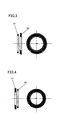
- Fig. 3 is an illustration showing ferromagnetic bodies having opposite surfaces of different shapes, that is, the inner diameter of ring-shaped impeller-side ferromagnetic body 51 (second ferromagnetic body) is made larger than the inner diameter of ring-shaped casing-side ferromagnetic body 52 (third ferromagnetic body), and the outer diameter of the second ferromagnetic body is made smaller than the outer diameter of the third ferromagnetic body.
- Fig. 4 is an illustration showing ferromagnetic bodies having opposite surfaces of different shapes, that is, the inner diameter of ring-shaped impeller-side ferromagnetic body 51 (second ferromagnetic body) is made smaller than the inner diameter of ring-shaped casing-side ferromagnetic body 52 (third ferromagnetic body), and the outer diameter of the second ferromagnetic body is made larger than the outer diameter of the third ferromagnetic body.
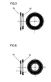
- Fig. 5 is an illustration showing ferromagnetic bodies having opposite surfaces of different shapes, that is, the inner and outer diameters of ring-shaped impeller-side ferromagnetic body 51 (second ferromagnetic body) are made larger than the inner and outer diameters of casing-side ferromagnetic body 52 (third ferromagnetic body), respectively.
- Fig. 6 is an illustration showing ferromagnetic bodies having opposite surfaces of different shapes, that is, the inner and outer diameters of ring-shaped impeller-side ferromagnetic body 51 (second ferromagnetic body) are made smaller than the inner and outer diameters of casing-side ferromagnetic body 52 (third ferromagnetic body), respectively.
- Fig. 7 is an illustration showing ferromagnetic bodies having opposite surfaces of different shapes, that is, impeller-side ferromagnetic body 51 (second ferromagnetic body) has a ring-shape, and casing-side ferromagnetic body 52 (third ferromagnetic body) is formed of four bar-magnets all magnetized in the same direction.
- Fig. 8 is an illustration showing ferromagnetic bodies having opposite surfaces of different shapes, that is, casing-side ferromagnetic body 52 (third ferromagnetic body) has a ring-shape, and impeller-side ferromagnetic body 51 (second ferromagnetic body) is formed of sixteen bar-magnets all magnetized in the same direction.
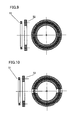
- Fig. 9 is an illustration showing ferromagnetic bodies having opposite surfaces of different shapes, that is, casing-side ferromagnetic body 52 (third ferromagnetic body) has a ring-shape, and impeller-side ferromagnetic body 51 (second ferromagnetic body) is formed of two plate-magnets magnetized in the same direction.
- Fig. 10 is an illustration showing ferromagnetic bodies having opposite surfaces of different shapes, that is, impeller-side ferromagnetic body 51 (second ferromagnetic body) has a ring-shape, and casing-side ferromagnetic body 52 (third ferromagnetic body) is formed of two plate-magnets magnetized in the same direction.
- Fig. 11 shows a magnetically levitated pump of a first prior art example having
an electro-
magnet 31 for magnetic bearing and amotor 13 provided on opposite sides of animpeller 23. - Fig. 12 shows a magnetically levitated pump of the second prior art example,
having
motor 13 and electro-magnets 31 for magnetic bearing arranged in a space on the same side. - Fig. 13 shows a magnetically levitated pump with a leakage flux shielding
structure in which a ferromagnetic body 53 (fourth ferromagnetic body) is arranged on
that side of casing-side
ferromagnetic body 52 which does not face toimpeller 23. -
- The invention according to the first embodiment is, as shown in Fig. 1, directed to a magnetically levitated
pump 1 including: apump unit 20 provided with a disk-shapedimpeller 23 for feeding liquid; and anactuator unit 40 having amotor rotor 15 transmitting rotary driving force toimpeller 23 and electro-magnets 31 for magnetic bearing exerting an attractive force onimpeller 23, arranged in the same direction toimpeller 23; wherein
a soft magnetic member 26 (first ferromagnetic body) opposite to the electro-magnets is provided on the actuator-facing impeller surface, opposite to elector-magnets 31 for magnetic bearing;
an impeller-side ferromagnetic body 51 (second ferromagnetic body) is provided on the casing-faced impeller surface;
a casing-side ferromagnetic body 52 (third ferromagnetic body) is provided opposite to impeller-side ferromagnetic body 51 (second ferromagnetic body) for attractingimpeller 23 toward thecasing 50;
a current flowing through electro-magnets 31 for magnetic bearing is controlled to balance (1) "the attractive force between electro-magnets 31 for magnetic bearing and soft magnetic member 26 (first ferromagnetic body)", (2) "the attractive force between impeller-side ferromagnetic body 51 (second ferromagnetic body) and casing-side ferromagnetic body 52 (third ferromagnetic body)", (3) "the force acting onimpeller 23 generated by the rotary driving means (in Fig. 1, the attractive force between impeller-sidepermanent magnets 24 and rotor-side permanent magnets 14)" and (4) "disturbances acting onimpeller 23", so that the impeller is magnetically levitated; and wherein
surfaces of impeller-side ferromagnetic body 51 (second ferromagnetic body) and casing-side ferromagnetic body 52 (third ferromagnetic body) opposite to each other are adapted to have different shapes so that maximum required attractive force f2 of electro-magnets 31 for magnetic bearing is reduced, thereby enabling reduction in length L5 of the electro-magnets for the magnetic bearing. - The invention according to the second embodiment is, as shown in Figs. 3 to 10, directed to the magnetically levitated pump of the first embodiment, wherein impeller-side ferromagnetic body 51 (second ferromagnetic body) or casing-side ferromagnetic body 52 (third ferromagnetic body) has a ring-shape.
- The invention according to the third embodiment is, as shown in Figs. 7 to 10, directed to the magnetically levitated pump of the first or second embodiment, wherein impeller-side ferromagnetic body 51 (second ferromagnetic body) or casing-side ferromagnetic body 52 (third ferromagnetic body) is formed of a plurality of ferromagnetic bodies arranged in the circumferential direction.
- The invention according to the fourth embodiment is, as shown in Fig. 3 or 5 or Figs. 7 to 10, directed to the magnetically levitated pump of the first to third embodiments, wherein the diameter of an approximated inscribed circle of impeller-side ferromagnetic body 51 (second ferromagnetic body) is made larger than the diameter of an approximated inscribed circle of casing-side ferromagnetic body 52 (third ferromagnetic body).
- The invention according to the fifth embodiment is, as shown in Fig. 4 or 6, directed to the magnetically levitated pump of the first to third embodiments, wherein the diameter of an approximated inscribed circle of impeller-side ferromagnetic body 51 (second ferromagnetic body) is made smaller than the diameter of an approximated inscribed circle of casing-side ferromagnetic body 52 (third ferromagnetic body).
- The invention according to the sixth embodiment is, as shown in Fig. 4 or 5, directed to the magnetically levitated pump of the first to third embodiments, wherein the diameter of an approximated circumscribed circle of impeller-side ferromagnetic body 51 (second ferromagnetic body) is made larger than the diameter of an approximated circumscribed circle of casing-side ferromagnetic body 52 (third ferromagnetic body).
- The invention according to the seventh embodiment is, as shown in Fig. 3 or Figs. 6 to 10, directed to the magnetically levitated pump of the first to third embodiments, wherein the diameter of an approximated circumscribed circle of impeller-side ferromagnetic body 51 (second ferromagnetic body) is made smaller than the diameter of an approximated circumscribed circle of casing-side ferromagnetic body 52 (third ferromagnetic body).
- The invention according to the eighth embodiment is directed to the magnetically levitated pump of the first to seventh embodiments, wherein impeller-side ferromagnetic body 51 (second ferromagnetic body) is a permanent magnet, or casing-side ferromagnetic body 52 (third ferromagnetic body) is a permanent magnet.
- The invention according to the ninth embodiment is, as shown in Fig. 13, directed to the magnetically levitated pump of the first to eighth embodiments, wherein a ferromagnetic body 53 (fourth ferromagnetic body) is arranged on that side of casing-side ferromagnetic body 52 (third ferromagnetic body) which does not face to
impeller 23, so as to suppress leakage flux to the outside of the pump. - The invention according to the tenth embodiment is, as shown in Fig. 1, directed to the magnetically levitated pump of the first to ninth embodiments, wherein the rotor-side permanent magnet 14 (first permanent magnet) is arranged on that surface of
rotor 12 which facesimpeller 23, and the impeller-side permanent magnet 24 (second permanent magnet) is arranged opposite thereto on the surface ofimpeller 23, whereby a magnetic coupling is formed by rotor-sidepermanent magnet 14 and impeller-sidepermanent magnet 24,rotor 12 is rotated andimpeller 23 is driven and rotated. - The invention according to the eleventh embodiment is directed to the magnetically levitated pump of the first to tenth embodiments, used as a blood pump.
- Fig. 1 shows a magnetically levitated pump in which, similar to the second prior art example,
motor 13 and electro-magnets 31 for magnetic bearing are arranged in a space on the same side. Referring to Fig. 1, the magnetically levitated pump of the present invention will be described. Functions similar to those of Fig. 12 are denoted by the same reference characters, and description thereof will not be repeated. - Similar to the second prior art example described with reference to Fig. 12 above, magnetically levitated
pump 1 of the present invention shown in Fig. 1 includes: apump unit 20 provided with a disk-shapedimpeller 23 for feeding liquid; anactuator unit 40 having amotor 13 for rotatingimpeller 23 and electro-magnets 31 for magnetic bearing exerting an attractive force onimpeller 23, arranged in the same direction toimpeller 23; and acasing unit 50 having aposition sensor 47 arranged thereon, for measuring levitation position ofimpeller 23. - In magnetically levitated
pump 1 of the present invention having such a structure, a current flowing through electro-magnets 31 for magnetic bearing is controlled to balance the attractive force between electro-magnets 31 for magnetic bearing and soft magnetic member 26 (first ferromagnetic body) opposite to the electro-magnets provided on the actuator-facing impeller surface opposite to electro-magnets 31 for magnetic bearing, the attractive force between an impeller-side ferromagnetic body 51 (second ferromagnetic body) provided on the casing-faced impeller surface and a casing-side ferromagnetic body 52 (third ferromagnetic body) opposite to impeller-side ferromagnetic body 51 (second ferromagnetic body) and attractingimpeller 23 toward thecasing 50, the force acting on impeller generated by the rotary driving means (in Fig. 1, the attractive force between impeller-sidepermanent magnets 24 and rotor-side permanent magnets 14) and disturbance influencing the impeller, so that the impeller is magnetically levitated. - Different from the first and second prior art examples, in magnetically levitated
pump 1 of the present invention, opposite surfaces of impeller-side ferromagnetic body 51 (second ferromagnetic body) and casing-side ferromagnetic body 52 (third ferromagnetic body) have different shapes, so that the maximum required attractive force of electro-magnets 31 for magnetic bearing is reduced from f1 of the second prior art example to f2, whereby the length of the electro-magnets of the magnetic bearing is reduced from L4 of the second prior art example to L5, and as a result, the magnetically levitated pump can be made compact by a volume corresponding to a cylindrical body of La x Lb, that is the product of axial length La of pump outer housing and reduction width Lb in diametral direction of pump outer housing. - Figs. 2A and 2B are characteristic diagrams of impeller levitation position and impeller force, representing a relation between the position of impeller levitation from electro-magnets/
impeller dividing wall 35 and position sensor/impeller dividing wall 36 in pump chamber 22 (abscissa) and the force acting on impeller 23 (ordinate). Fig. 2A is a characteristic diagram of impeller levitation position and impeller force of the conventional structure shown in Fig. 12, and Fig. 2B is a characteristic diagram of impeller levitation position and impeller force of the structure of the present invention shown in Fig. 1. Both figures represent a state in which the attractive forces Fm1 and Fm2 to the direction of the actuator generated between impeller-sidepermanent magnets 24 and rotor-sidepermanent magnets 14 are the same. - The abscissa represents the distance from electro-magnets/
impeller dividing wall 35 toimpeller 23, inpump chamber 22. The ordinate represents the force acting onimpeller 23. In the figure, as the forces acting onimpeller 23, (1) attractive force Fc to the casing side generated between impeller-side ferromagnetic body 51 (second ferromagnetic body) and the casing-side ferromagnetic body 52 (third ferromagnetic body) and (2) attractive force Fm to the actuator side generated between impeller-sidepermanent magnets 24 and rotor-sidepermanent magnets 14 are denoted. Further, an electro-magnet attractive force Fr required between electro-magnets 31 for magnetic bearing and softmagnetic member 26 opposite to the electro-magnets for levitatingimpeller 23 to the levitation position against the above-identified attractive forces is calculated by adding the attractive force Fc to the casing side and attractive force Fm to the actuator side, and denoted. In Figs. 2A and 2B, the attractive force by whichimpeller 23 is attracted to the side of casing is indicated as (+) along the ordinate, and it is assumed that there is no other disturbance affecting theimpeller 23. - In the following, the characteristic diagram of impeller levitation position and impeller force of the conventional structure of Fig. 2A will be compared with the characteristic diagram of impeller levitation position and impeller force of the structure in accordance with the present invention shown in Fig. 2B.
- The movable range of
impeller 23 inpump chamber 22 is limited by electro-magnets/impeller dividing wall 35 and position sensor/impeller dividing wall 36. An electro-magnet can generate only the attractive force and not the repulsive force. Therefore, in both structures shown in Figs. 12 and 1, in order to control the levitation position ofimpeller 23 by electro-magnets 31 for magnetic bearing, it is always necessary that | attractive force Fc to the casing side| > |attractive force Fm to the actuator side|, in the movable range ofimpeller 23 inpump chamber 22. - As shown in Fig. 2B, by making difference between the shapes of opposite surfaces of impeller-side ferromagnetic body 51 (second ferromagnetic body) and casing-side ferromagnetic body (third ferromagnetic body) opposite thereto, the amount of increase/decrease of the attractive force Fc to the casing side caused by the positional change of
impeller 23 can be made smaller, and therefore, the change in attractive force Fr of electro-magnets 31 for magnetic bearing can also be made smaller then in the case of Fig. 2A, by the position of the impeller. Therefore, maximum required attractive force of electro-magnets 31 for magnetic bearing can be made smaller than the maximum required attractive force f1 shown in Fig. 2A. As the maximum required attractive force of electro-magnets 31 for magnetic bearing can be reduced, it becomes possible to reduce the attractive force of electro-magnets 31 for magnetic bearing, it becomes possible to reduce the number of coil windings inside and to make shorter the length of electro-magnets 31 for magnetic bearing. As a result, in Fig. 1, the number of coil windings around electro-magnets 31 for magnetic bearing can be reduced from that of Fig. 12, and hence, electro-magnets 31 for magnetic bearing and the pump itself can be made compact. - As shown in Fig. 2B, other possible methods of reducing the attractive force Fc to the casing side generated between impeller-side ferromagnetic body 51 (second ferromagnetic body) and the casing-side ferromagnetic body 52 (third ferromagnetic body) may include (1) the method in which the impeller-side ferromagnetic body 51 (second ferromagnetic body) is made thicker and the casing-side ferromagnetic body 52 (third ferromagnetic body) is placed away from the impeller-side ferromagnetic body 51 (second ferromagnetic body), and (2) the method in which the thickness of the impeller-side ferromagnetic body 51 (second ferromagnetic body) is kept unchanged, and the casing-side ferromagnetic body 52 (third ferromagnetic body) is made thicker and placed away from the impeller-side ferromagnetic body 51 (second ferromagnetic body). Both of these methods are undesirable in view of reduction in size of the pump, as the length of the pump in the axial direction (left/right direction in the figure) increases in both methods.
- In Fig. 1,
position sensor 47 is arranged oncasing unit 50. The sensor may be arranged on the same side and near electro-magnets 31 for magnetic bearing, as in the first prior art example shown in Fig. 11. Further, though a magnetic coupling is provided for rotationally drivingimpeller 23 in Fig. 1, a method may be adopted in which the impeller is rotationally driven by electrically providing a rotational magnetic field on the impeller-sidepermanent magnets 24. - Figs. 3 to 10 represent embodiments of the present invention related to the arrangement and shapes of impeller-side ferromagnetic body 51 (second ferromagnetic body) and casing-side ferromagnetic body 52 (third ferromagnetic body). In these figures, only the relations and shapes of these two ferromagnetic bodies are shown, and other components, structures and the like of the pump are not addressed. Further, in these figures, perspective views along the axial direction are shown on the right side.
- Fig. 3 shows ferromagnetic bodies having opposite surfaces of different shapes, in which both ferromagnetic bodies have a ring-shape, and the inner diameter of impeller-side ferromagnetic body 51 (second ferromagnetic body) is made larger than the inner diameter of casing-side ferromagnetic body 52 (third ferromagnetic body), and the outer diameter of impeller-side ferromagnetic body 51 (second ferromagnetic body) is made smaller than the inner diameter of casing-side ferromagnetic body 52 (third ferromagnetic body). Though the two ferromagnetic bodies are adapted to have different inner and outer diameters in this example, one of the inner and outer diameters may be the same. Further, the materials of the two ferromagnetic bodies may be selected such that the attractive force acts in mutually opposite directions, and one or both of the ferromagnetic bodies may be formed of a permanent magnet.
- Fig. 4 shows ferromagnetic bodies having opposite surfaces of different shapes, in which both ferromagnetic bodies have a ring-shape, and the inner diameter of impeller-side ferromagnetic body 51 (second ferromagnetic body) is made smaller than the inner diameter of casing-side ferromagnetic body 52 (third ferromagnetic body), and the outer diameter of impeller-side ferromagnetic body 51 (second ferromagnetic body) is made larger than the inner diameter of casing-side ferromagnetic body 52 (third ferromagnetic body). Though the two ferromagnetic bodies are adapted to have different inner and outer diameters in this example, one of the inner and outer diameters may be the same. Further, the materials of the two ferromagnetic bodies may be selected such that the attractive force acts in mutually opposite directions, and one or both of the ferromagnetic bodies may be formed of a permanent magnet.
- Fig. 5 shows ferromagnetic bodies having opposite surfaces of different shapes, in which both ferromagnetic bodies have a ring-shape, and the inner and outer diameters of impeller-side ferromagnetic body 51 (second ferromagnetic body) are made larger than the inner and outer diameters of casing-side ferromagnetic body 52 (third ferromagnetic body), respectively. Though the two ferromagnetic bodies are adapted to have different inner and outer diameters in this example, one of the diameters may be the same. Further, the materials of the two ferromagnetic bodies may be selected such that the attractive force acts in mutually opposite directions, and one or both of the ferromagnetic bodies may be formed of a permanent magnet.
- Fig. 6 shows ferromagnetic bodies having opposite surfaces of different shapes, in which both ferromagnetic bodies have a ring-shape, and the inner and outer diameters of impeller-side ferromagnetic body 51 (second ferromagnetic body) are made smaller than the inner and outer diameters of casing-side ferromagnetic body 52 (third ferromagnetic body), respectively. Though the two ferromagnetic bodies are adapted to have different inner and outer diameters in this example, one of the diameters may be the same. Further, the materials of the two ferromagnetic bodies may be selected such that the attractive force acts in mutually opposite directions, and one or both of the ferromagnetic bodies may be formed of a permanent magnet.
- Fig. 7 shows ferromagnetic bodies having opposite surfaces of different shapes, in which impeller-side ferromagnetic body 51 (second ferromagnetic body) has a ring-shape, and casing-side ferromagnetic body 52 (third ferromagnetic body) is formed of four bar-magnets all magnetized in the same direction. Further, the diameter of an inscribed circle of casing-side ferromagnetic body 52 (third ferromagnetic body) is smaller than the inner diameter of impeller-side ferromagnetic body 51 (second ferromagnetic body), and the diameter of a circumscribed circle of casing-side ferromagnetic body 52 (third ferromagnetic body) is larger than the outer diameter of impeller-side ferromagnetic body 51 (second ferromagnetic body).
- Though the inner diameter and the diameter of the inscribed circle, and the outer diameter and the diameter of the circumscribed circle of the two ferromagnetic bodies are made different from each other in this example, one of these may be the same. Though the ferromagnetic body is implemented by four bar-magnets here, the number thereof is not limited. Further, casing-side ferromagnetic body 52 (third ferromagnetic body) may be a soft magnetic member. The materials of impeller-side
ferromagnetic body 51 and casing-sideferromagnetic body 52 may be selected such that the attractive force acts in mutually opposite directions, and both may be permanent magnets, or impeller-sideferromagnetic body 51 may be formed of a permanent magnet and casing-sideferromagnetic body 52 may be formed of a soft magnetic body. - Fig. 8 shows ferromagnetic bodies having opposite surfaces of different shapes, in which casing-side ferromagnetic body 52 (third ferromagnetic body) has a ring-shape, and impeller-side ferromagnetic body 51 (second ferromagnetic body) is formed of sixteen bar-magnets all magnetized in the same direction. Further, the diameter of an inscribed circle of impeller-side ferromagnetic body 51 (second ferromagnetic body) is made larger than the inner diameter of casing-side ferromagnetic body 52 (third ferromagnetic body), and the diameter of a circumscribed circle of impeller-side ferromagnetic body 51 (second ferromagnetic body) is made smaller than the outer diameter of casing-side ferromagnetic body 52 (third ferromagnetic body).
- Though the inner diameter and the diameter of the inscribed circle, and the outer diameter and the diameter of the circumscribed circle of the two ferromagnetic bodies are made different from each other in this example, one of these may be the same. Though the ferromagnetic body is implemented by sixteen bar-magnets here, the number thereof is not limited. Further, casing-side ferromagnetic body 52 (third ferromagnetic body) may be a soft magnetic member. The materials of impeller-side
ferromagnetic body 51 and casing-sideferromagnetic body 52 may be selected such that the attractive force acts in mutually opposite directions, and both may be permanent magnets, or impeller-sideferromagnetic body 51 may be formed of a permanent magnet and casing-sideferromagnetic body 52 may be formed of a soft magnetic body. - Fig. 9 shows ferromagnetic bodies having opposite surfaces of different shapes, in which casing-side ferromagnetic body 52 (third ferromagnetic body) has a ring-shape, and impeller-side ferromagnetic body 51 (second ferromagnetic body) is formed of two plate-magnets magnetized in the same direction.
- Though the inner diameter and the diameter of the inscribed circle, and the outer diameter and the diameter of the circumscribed circle of the two ferromagnetic bodies are made different from each other in this example, one of these may be the same. Though the impeller-side
ferromagnetic body 51 is implemented by two plate-shaped magnets here, the number thereof is not limited. Further, casing-side ferromagnetic body 52 (third ferromagnetic body) may be a soft magnetic member. The materials of impeller-sideferromagnetic body 51 and casing-sideferromagnetic body 52 may be selected such that the attractive force acts in mutually opposite directions, and both may be permanent magnets, or impeller-sideferromagnetic body 51 may be formed of a permanent magnet and casing-sideferromagnetic body 52 may be formed of a soft magnetic body. - Fig. 10 shows ferromagnetic bodies having opposite surfaces of different shapes, in which impeller-side ferromagnetic body 51 (second ferromagnetic body) has a ring-shape, and casing-side ferromagnetic body 52 (third ferromagnetic body) is formed of two plate-magnets magnetized in the same direction.
- Though the inner diameter and the diameter of the inscribed circle, and the outer diameter and the diameter of the circumscribed circle of the two ferromagnetic bodies are made different from each other in this example, one of these may be the same. Though the casing-side
ferromagnetic body 52 is implemented by two plate-shaped magnets here, the number thereof is not limited. The materials of impeller-sideferromagnetic body 51 and casing-sideferromagnetic body 52 may be selected such that the attractive force acts in mutually opposite directions, and both may be permanent magnets, or impeller-sideferromagnetic body 51 may be formed of a permanent magnet and casing-sideferromagnetic body 52 may be formed of a soft magnetic body. - Fig. 13 shows a magnetically levitated pump with a leakage flux shielding structure preventing leakage to the outside of
pump 1, in which a ferromagnetic body 53 (fourth ferromagnetic body) is arranged on that side of casing-sideferromagnetic body 52 which does not face toimpeller 23. Different from Fig. 1, in this example, ferromagnetic body 53 (fourth ferromagnetic body) is placed, so that leakage flux from casing-sideferromagnetic body 52 to the outside ofpump 1 can be shielded, and any flux from the outside ofpump 1 can also be shielded, so that stable lifting ofimpeller 23 is ensured. Here, ferromagnetic body 53 (fourth ferromagnetic body) may be of a soft magnetic material or a hard magnetic material. - Though
position sensor 47 is arranged near casing-sideferromagnetic body 52 in the pump structure shown in Fig. 1, it may be arranged inactuator unit 40. - According to the present invention, a current flowing through electro-magnets 31 for magnetic bearing is controlled to balance (1) the attractive force between electro-magnets 31 for magnetic bearing and soft magnetic member 26 (first ferromagnetic body) opposite to the electro-magnets provided on the actuator-facing impeller surface opposite to electro-magnets 31 for magnetic bearing, (2) the attractive force between impeller-side ferromagnetic body 51 (second ferromagnetic body) provided on the casing-faced impeller surface and casing-side ferromagnetic body 52 (third ferromagnetic body) opposite to impeller-side ferromagnetic body 51 (second ferromagnetic body) and attracting impeller 23 toward the casing 50, (3) the force acting on impeller generated by the rotary driving means (in Fig. 1, the attractive force between impeller-side permanent magnets 24 and rotor-side permanent magnets 14) and (4) other disturbance influencing the impeller, so that the impeller is magnetically levitated; and surfaces of impeller-side ferromagnetic body 51 (second ferromagnetic body) and casing-side ferromagnetic body 52 (third ferromagnetic body) opposite to each other are adapted to have different shapes so that maximum required attractive force f2 of electro-magnets 31 for magnetic bearing is reduced, thereby enabling reduction in length L5 of the electro-magnets for the magnetic bearing.
- Although the present invention has been described and illustrated in detail, it is clearly understood that the same is by way of illustration and example only and is not to be taken by way of limitation, the spirit and scope of the present invention being limited only by the terms of the appended claims.
Claims (11)
- A magnetically levitated pump, comprising:a pump unit (20) including a disk-shaped impeller (23) for feeding liquid;a magnetic bearing unit (40) provided opposite to one of end faces along an axial direction of said impeller (23); anda casing unit (50) provided opposite to the other of said end faces; wherein said magnetic bearing unit (40) includesrotary driving means (12-14, 24) for transmitting a rotational driving force to said impeller (23), andan electro-magnet (31) for magnetic bearing;said pump unit (20) includesa soft magnetic member (26) opposite to electro-magnet provided on said one of said end faces of said impeller (23) and provided opposite to said electro-magnet (31) for magnetic bearing, andan impeller-side ferromagnetic body (51) provided on said other of said end faces of said impeller (23);said casing unit (50) includes a casing-side ferromagnetic body (52) provided opposite to said impeller-side ferromagnetic body (51) and attracting said impeller (23) toward said casing unit (50);said electro-magnet (31) for magnetic bearing has a magnetizing current flowing therethrough controlled to balance an attractive force between said electro-magnet (31) for magnetic bearing and said soft magnetic member (26) opposite to electro-magnet, an attractive force between said impeller-side ferromagnetic body (51) and said casing-side ferromagnetic body (52), a force acting on said impeller (23) generated by said rotary driving means (12-14, 24), and other disturbance influencing said impeller (23); andopposite surfaces of said impeller-side ferromagnetic body (51) and said casing-side ferromagnetic body (52) are adapted to have mutually different shapes each other, so that maximum required attractive force (f2) between said electro-magnet (31) for magnetic bearing and said soft magnetic member (26) opposite to electro-magnet becomes smaller than a prescribed force (f1).
- The magnetically levitated pump according to claim 1, wherein
said impeller-side ferromagnetic body (51) or said casing-side ferromagnetic body (52) has a ring-shape. - The magnetically levitated pump according to claim 1 (or 2) wherein
said impeller-side ferromagnetic body (51) or said casing-side ferromagnetic body (52) is formed of a plurality of ferromagnetic bodies arranged in a circumferential direction. - The magnetically levitated pump according to claim 1 (any of claims 1 to 3), wherein
diameter of an approximated inscribed circle of said impeller-side ferromagnetic body (51) is larger than diameter of an approximated inscribed circle of said casing-side ferromagnetic body (52). - The magnetically levitated pump according to claim 1 (any of claims 1 to 3), wherein
diameter of an approximated inscribed circle of said impeller-side ferromagnetic body (51) is smaller than diameter of an approximated inscribed circle of said casing-side ferromagnetic body (52). - The magnetically levitated pump according to claim 1 (any of claims 1 to 3), wherein
diameter of an approximated circumscribed circle of said impeller-side ferromagnetic body (51) is larger than diameter of an approximated circumscribed circle of said casing-side ferromagnetic body (52). - The magnetically levitated pump according to claim 1 (any of claims 1 to 3), wherein
diameter of an approximated circumscribed circle of said impeller-side ferromagnetic body (51) is smaller than diameter of an approximated circumscribed circle of said casing-side ferromagnetic body (52). - The magnetically levitated pump according to claim 1 (any of claims 1 to 7), wherein
said impeller-side ferromagnetic body (51) or said casing-side ferromagnetic body (52) is formed of a permanent magnet. - The magnetically levitated pump according to claim 1 (any of claims 1 to 8), wherein
said casing unit (50) further includes a ferromagnetic body (53) arranged on that side of casing-side ferromagnetic body (52) which does not face to said impeller (23). - The magnetically levitated pump according to claim 1 (any of claims 1 to 9), wherein
said rotary driving means (12-14, 24) includes a rotor (12) provided opposite to said impeller (23),
said impeller (23) has an impeller-side permanent magnet (24) arranged on said one of said end faces,
said rotor (12) has a rotor-side permanent magnet (14) arranged opposite to said impeller-side permanent magnet (24),
said rotary driving means (12-14, 24) rotationally drives said impeller (23) by a magnetic coupling formed between said impeller-side permanent magnet (24) and said rotor-side permanent magnet (14). - The magnetically levitated pump according to claim 1 (any of claims 1 to 10), used as a blood pump.
Applications Claiming Priority (2)
| Application Number | Priority Date | Filing Date | Title |
|---|---|---|---|
| JP2003363607 | 2003-10-23 | ||
| JP2003363607A JP4767488B2 (en) | 2003-10-23 | 2003-10-23 | Magnetic levitation pump |
Publications (3)
| Publication Number | Publication Date |
|---|---|
| EP1526286A2 true EP1526286A2 (en) | 2005-04-27 |
| EP1526286A3 EP1526286A3 (en) | 2005-05-18 |
| EP1526286B1 EP1526286B1 (en) | 2006-12-06 |
Family
ID=34386530
Family Applications (1)
| Application Number | Title | Priority Date | Filing Date |
|---|---|---|---|
| EP04025066A Not-in-force EP1526286B1 (en) | 2003-10-23 | 2004-10-21 | Magnetically levitated pump utilizing magnetic bearings |
Country Status (5)
| Country | Link |
|---|---|
| US (1) | US7467930B2 (en) |
| EP (1) | EP1526286B1 (en) |
| JP (1) | JP4767488B2 (en) |
| AT (1) | ATE347654T1 (en) |
| DE (1) | DE602004003540T2 (en) |
Cited By (11)
| Publication number | Priority date | Publication date | Assignee | Title |
|---|---|---|---|---|
| EP2009233A1 (en) * | 2007-06-29 | 2008-12-31 | Anest Iwata Corporation | Magnetic bearing and coupling device |
| CZ300147B6 (en) * | 2007-08-10 | 2009-02-25 | Vysoké ucení technické v Brne | Glandless centrifugal pump with integrated disk-type motor |
| EP2538086A1 (en) * | 2010-02-16 | 2012-12-26 | NTN Corporation | Centrifugal pump device |
| US9623161B2 (en) | 2014-08-26 | 2017-04-18 | Tc1 Llc | Blood pump and method of suction detection |
| US9850906B2 (en) | 2011-03-28 | 2017-12-26 | Tc1 Llc | Rotation drive device and centrifugal pump apparatus employing same |
| US10052420B2 (en) | 2013-04-30 | 2018-08-21 | Tc1 Llc | Heart beat identification and pump speed synchronization |
| US10117983B2 (en) | 2015-11-16 | 2018-11-06 | Tc1 Llc | Pressure/flow characteristic modification of a centrifugal pump in a ventricular assist device |
| US10166318B2 (en) | 2015-02-12 | 2019-01-01 | Tc1 Llc | System and method for controlling the position of a levitated rotor |
| US10245361B2 (en) | 2015-02-13 | 2019-04-02 | Tc1 Llc | Impeller suspension mechanism for heart pump |
| US10371152B2 (en) | 2015-02-12 | 2019-08-06 | Tc1 Llc | Alternating pump gaps |
| US10506935B2 (en) | 2015-02-11 | 2019-12-17 | Tc1 Llc | Heart beat identification and pump speed synchronization |
Families Citing this family (38)
| Publication number | Priority date | Publication date | Assignee | Title |
|---|---|---|---|---|
| DE102005052559A1 (en) * | 2005-11-02 | 2007-05-10 | Behr Gmbh & Co. Kg | Adjustable drive for a motor vehicle, in particular for a coolant pump |
| US20070185369A1 (en) * | 2006-02-03 | 2007-08-09 | Mahmood Mirhoseini | Cardiac assist device and method |
| US8431648B2 (en) * | 2006-03-31 | 2013-04-30 | Milliken & Company | Coated substrates and polymer dispersions suitable for use in making the same |
| US8267636B2 (en) | 2007-05-08 | 2012-09-18 | Brooks Automation, Inc. | Substrate transport apparatus |
| US8823294B2 (en) | 2007-06-27 | 2014-09-02 | Brooks Automation, Inc. | Commutation of an electromagnetic propulsion and guidance system |
| CN101790673B (en) | 2007-06-27 | 2013-08-28 | 布鲁克斯自动化公司 | Position feedback for self bearing motor |
| US8283813B2 (en) | 2007-06-27 | 2012-10-09 | Brooks Automation, Inc. | Robot drive with magnetic spindle bearings |
| US8659205B2 (en) | 2007-06-27 | 2014-02-25 | Brooks Automation, Inc. | Motor stator with lift capability and reduced cogging characteristics |
| KR101660894B1 (en) | 2007-06-27 | 2016-10-10 | 브룩스 오토메이션 인코퍼레이티드 | Multiple dimension position sensor |
| US9752615B2 (en) | 2007-06-27 | 2017-09-05 | Brooks Automation, Inc. | Reduced-complexity self-bearing brushless DC motor |
| CN101801817B (en) | 2007-07-17 | 2015-07-22 | 布鲁克斯自动化公司 | Substrate processing apparatus with motors integral to chamber walls |
| US9044535B2 (en) * | 2007-08-07 | 2015-06-02 | Terumo Cardiovascular Systems Corp. | Extracorporeal blood pump with disposable pump head portion having magnetically levitated impeller |
| JP5171953B2 (en) | 2008-06-23 | 2013-03-27 | テルモ株式会社 | Blood pump device |
| EP2372160B1 (en) | 2008-12-08 | 2014-07-30 | Thoratec Corporation | Centrifugal pump device |
| JP5378010B2 (en) | 2009-03-05 | 2013-12-25 | ソラテック コーポレーション | Centrifugal pump device |
| CN102341600B (en) | 2009-03-06 | 2014-12-10 | 胸腔科技有限公司 | Centrifugal pump device |
| JP5378012B2 (en) * | 2009-03-06 | 2013-12-25 | ソラテック コーポレーション | Centrifugal pump device |
| JP5378060B2 (en) * | 2009-05-08 | 2013-12-25 | ソラテック コーポレーション | Centrifugal pump device |
| JP5572832B2 (en) | 2010-03-26 | 2014-08-20 | ソーラテック コーポレイション | Centrifugal blood pump device |
| JP5681403B2 (en) | 2010-07-12 | 2015-03-11 | ソーラテック コーポレイション | Centrifugal pump device |
| JP5577506B2 (en) | 2010-09-14 | 2014-08-27 | ソーラテック コーポレイション | Centrifugal pump device |
| JP5631236B2 (en) * | 2011-02-21 | 2014-11-26 | 三菱電機株式会社 | Pump and heat pump device |
| JP4969695B1 (en) | 2011-09-15 | 2012-07-04 | 三菱重工業株式会社 | Drive device for magnetic coupling pump and magnetic coupling pump unit |
| JP6083929B2 (en) | 2012-01-18 | 2017-02-22 | ソーラテック コーポレイション | Centrifugal pump device |
| US20140161651A1 (en) * | 2012-12-11 | 2014-06-12 | Micropump, Inc, a Unit of IDEX Corporation | Compact integrated-drive pumps |
| US9371826B2 (en) | 2013-01-24 | 2016-06-21 | Thoratec Corporation | Impeller position compensation using field oriented control |
| US9556873B2 (en) | 2013-02-27 | 2017-01-31 | Tc1 Llc | Startup sequence for centrifugal pump with levitated impeller |
| US9713663B2 (en) | 2013-04-30 | 2017-07-25 | Tc1 Llc | Cardiac pump with speed adapted for ventricle unloading |
| US9771938B2 (en) | 2014-03-11 | 2017-09-26 | Peopleflo Manufacturing, Inc. | Rotary device having a radial magnetic coupling |
| CN106300722A (en) * | 2015-05-18 | 2017-01-04 | 德昌电机(深圳)有限公司 | Motor and electrodynamic pump |
| US20170016449A1 (en) * | 2015-07-14 | 2017-01-19 | Hamilton Sundstrand Corporation | Axial-flux induction motor pump |
| US10177627B2 (en) | 2015-08-06 | 2019-01-08 | Massachusetts Institute Of Technology | Homopolar, flux-biased hysteresis bearingless motor |
| EP3135933B1 (en) * | 2015-08-25 | 2019-05-01 | ReinHeart GmbH | Active magnetic bearing |
| US9920764B2 (en) | 2015-09-30 | 2018-03-20 | Peopleflo Manufacturing, Inc. | Pump devices |
| US20180245596A1 (en) * | 2016-07-26 | 2018-08-30 | RELIAX MOTORES SA de CV | Integrated electric motor and pump assembly |
| EP3456367A1 (en) * | 2017-09-19 | 2019-03-20 | Abiomed Europe GmbH | Blood pump |
| WO2019125718A1 (en) | 2017-12-22 | 2019-06-27 | Massachusetts Institute Of Technology | Homopolar bearingless slice motors |
| US10947986B2 (en) * | 2018-07-11 | 2021-03-16 | Ch Biomedical (Usa) Inc. | Compact centrifugal pump with magnetically suspended impeller |
Citations (6)
| Publication number | Priority date | Publication date | Assignee | Title |
|---|---|---|---|---|
| EP0378251A2 (en) * | 1981-03-18 | 1990-07-18 | Günther Walter Otto Bramm | Magnetically suspended and rotated impellor pump apparatus |
| WO1999012587A1 (en) * | 1997-09-05 | 1999-03-18 | Ventrassist Pty Ltd | A rotary pump with hydrodynamically suspended impeller |
| WO1999053974A2 (en) * | 1998-04-22 | 1999-10-28 | University Of Utah | Implantable centrifugal blood pump with hybrid magnetic bearings |
| US6227817B1 (en) * | 1999-09-03 | 2001-05-08 | Magnetic Moments, Llc | Magnetically-suspended centrifugal blood pump |
| US6394769B1 (en) * | 1996-05-03 | 2002-05-28 | Medquest Products, Inc. | Pump having a magnetically suspended rotor with one active control axis |
| US6626644B2 (en) * | 2000-10-30 | 2003-09-30 | Ntn Corporation | Magnetically levitated pump and controlling circuit |
Family Cites Families (11)
| Publication number | Priority date | Publication date | Assignee | Title |
|---|---|---|---|---|
| JPH02241339A (en) * | 1989-03-14 | 1990-09-26 | Hitachi Ltd | Permanent magnet rotor for turbo-charger directly-connecting rotary machine |
| FR2715201B1 (en) * | 1994-01-19 | 1996-02-09 | Inst Nat Polytech Grenoble | Magnetic bearing and assembly comprising a stator part and a rotor part suspended by such a bearing. |
| JPH09170586A (en) * | 1995-12-18 | 1997-06-30 | Nippon Seiko Kk | Water pump |
| JP3818340B2 (en) * | 1997-09-26 | 2006-09-06 | 株式会社富士通ゼネラル | Permanent magnet motor |
| JP4612925B2 (en) * | 1999-12-27 | 2011-01-12 | Ntn株式会社 | Magnetic levitation pump |
| JP4555437B2 (en) * | 2000-07-10 | 2010-09-29 | Ntn株式会社 | Magnetic levitation pump device |
| JP2002021764A (en) * | 2000-07-11 | 2002-01-23 | Nidec Shibaura Corp | Magnet pump |
| JP4685227B2 (en) * | 2000-10-30 | 2011-05-18 | Ntn株式会社 | Magnetic levitation pump |
| JP3996775B2 (en) * | 2002-01-09 | 2007-10-24 | テルモ株式会社 | Centrifugal liquid pump device |
| US7070398B2 (en) * | 2003-09-25 | 2006-07-04 | Medforte Research Foundation | Axial-flow blood pump with magnetically suspended, radially and axially stabilized impeller |
| US7141966B2 (en) * | 2004-07-01 | 2006-11-28 | Denso Corporation | Rotation detecting apparatus |
-
2003
- 2003-10-23 JP JP2003363607A patent/JP4767488B2/en not_active Expired - Fee Related
-
2004
- 2004-10-21 EP EP04025066A patent/EP1526286B1/en not_active Not-in-force
- 2004-10-21 DE DE602004003540T patent/DE602004003540T2/en active Active
- 2004-10-21 US US10/968,931 patent/US7467930B2/en active Active
- 2004-10-21 AT AT04025066T patent/ATE347654T1/en not_active IP Right Cessation
Patent Citations (6)
| Publication number | Priority date | Publication date | Assignee | Title |
|---|---|---|---|---|
| EP0378251A2 (en) * | 1981-03-18 | 1990-07-18 | Günther Walter Otto Bramm | Magnetically suspended and rotated impellor pump apparatus |
| US6394769B1 (en) * | 1996-05-03 | 2002-05-28 | Medquest Products, Inc. | Pump having a magnetically suspended rotor with one active control axis |
| WO1999012587A1 (en) * | 1997-09-05 | 1999-03-18 | Ventrassist Pty Ltd | A rotary pump with hydrodynamically suspended impeller |
| WO1999053974A2 (en) * | 1998-04-22 | 1999-10-28 | University Of Utah | Implantable centrifugal blood pump with hybrid magnetic bearings |
| US6227817B1 (en) * | 1999-09-03 | 2001-05-08 | Magnetic Moments, Llc | Magnetically-suspended centrifugal blood pump |
| US6626644B2 (en) * | 2000-10-30 | 2003-09-30 | Ntn Corporation | Magnetically levitated pump and controlling circuit |
Cited By (19)
| Publication number | Priority date | Publication date | Assignee | Title |
|---|---|---|---|---|
| EP2009233A1 (en) * | 2007-06-29 | 2008-12-31 | Anest Iwata Corporation | Magnetic bearing and coupling device |
| CZ300147B6 (en) * | 2007-08-10 | 2009-02-25 | Vysoké ucení technické v Brne | Glandless centrifugal pump with integrated disk-type motor |
| EP2538086A1 (en) * | 2010-02-16 | 2012-12-26 | NTN Corporation | Centrifugal pump device |
| EP2538086A4 (en) * | 2010-02-16 | 2015-04-08 | Thoratec Corp | Centrifugal pump device |
| US9850906B2 (en) | 2011-03-28 | 2017-12-26 | Tc1 Llc | Rotation drive device and centrifugal pump apparatus employing same |
| US10052420B2 (en) | 2013-04-30 | 2018-08-21 | Tc1 Llc | Heart beat identification and pump speed synchronization |
| US9623161B2 (en) | 2014-08-26 | 2017-04-18 | Tc1 Llc | Blood pump and method of suction detection |
| US10856748B2 (en) | 2015-02-11 | 2020-12-08 | Tc1 Llc | Heart beat identification and pump speed synchronization |
| US10506935B2 (en) | 2015-02-11 | 2019-12-17 | Tc1 Llc | Heart beat identification and pump speed synchronization |
| US11712167B2 (en) | 2015-02-11 | 2023-08-01 | Tc1 Llc | Heart beat identification and pump speed synchronization |
| US10166318B2 (en) | 2015-02-12 | 2019-01-01 | Tc1 Llc | System and method for controlling the position of a levitated rotor |
| US10371152B2 (en) | 2015-02-12 | 2019-08-06 | Tc1 Llc | Alternating pump gaps |
| US10874782B2 (en) | 2015-02-12 | 2020-12-29 | Tc1 Llc | System and method for controlling the position of a levitated rotor |
| US11015605B2 (en) | 2015-02-12 | 2021-05-25 | Tc1 Llc | Alternating pump gaps |
| US11724097B2 (en) | 2015-02-12 | 2023-08-15 | Tc1 Llc | System and method for controlling the position of a levitated rotor |
| US11781551B2 (en) | 2015-02-12 | 2023-10-10 | Tc1 Llc | Alternating pump gaps |
| US10245361B2 (en) | 2015-02-13 | 2019-04-02 | Tc1 Llc | Impeller suspension mechanism for heart pump |
| US10117983B2 (en) | 2015-11-16 | 2018-11-06 | Tc1 Llc | Pressure/flow characteristic modification of a centrifugal pump in a ventricular assist device |
| US11639722B2 (en) | 2015-11-16 | 2023-05-02 | Tc1 Llc | Pressure/flow characteristic modification of a centrifugal pump in a ventricular assist device |
Also Published As
| Publication number | Publication date |
|---|---|
| DE602004003540T2 (en) | 2007-04-12 |
| JP4767488B2 (en) | 2011-09-07 |
| EP1526286B1 (en) | 2006-12-06 |
| JP2005127222A (en) | 2005-05-19 |
| US20050089422A1 (en) | 2005-04-28 |
| ATE347654T1 (en) | 2006-12-15 |
| EP1526286A3 (en) | 2005-05-18 |
| US7467930B2 (en) | 2008-12-23 |
| DE602004003540D1 (en) | 2007-01-18 |
Similar Documents
| Publication | Publication Date | Title |
|---|---|---|
| EP1526286B1 (en) | Magnetically levitated pump utilizing magnetic bearings | |
| US6641378B2 (en) | Pump with electrodynamically supported impeller | |
| EP3018352B1 (en) | Magnetic levitated pump | |
| US10177627B2 (en) | Homopolar, flux-biased hysteresis bearingless motor | |
| AU673886B2 (en) | Fluid pump with magnetically levitated impeller | |
| US6626644B2 (en) | Magnetically levitated pump and controlling circuit | |
| US5112202A (en) | Turbo pump with magnetically supported impeller | |
| EP2209186B1 (en) | Magnetically-levitated motor and pump | |
| US6227820B1 (en) | Axial force null position magnetic bearing and rotary blood pumps which use them | |
| US5106273A (en) | Vacuum pump for producing a clean molecular vacuum | |
| US8596999B2 (en) | Disposable centrifugal blood pump with magnetic coupling | |
| US6575717B2 (en) | Magnetically levitated pump | |
| EP1430919A1 (en) | Centrifugal blood pump apparatus | |
| WO2001002724A8 (en) | Blood pump having a magnetically suspended rotor | |
| JPH09303283A (en) | Magnetic levitation type pump | |
| EP1636497B1 (en) | Pump with an electrodinamically sumically supported impeller | |
| JP2009192041A (en) | Thrust force generation device, electromagnetic machine applying thrust force generation device | |
| JP4685227B2 (en) | Magnetic levitation pump | |
| JPH04148095A (en) | Turbo-type pump | |
| JP2019154572A (en) | Pump device | |
| JP2000240587A (en) | Closed fluid device | |
| JP5306741B2 (en) | Parallel intake pump and vacuum apparatus using the same | |
| JP5312876B2 (en) | Bearing device for rotating part and pump using the same | |
| JP3357639B2 (en) | Turbo type pump | |
| CN117028416A (en) | Magnetic bearing and pump device |
Legal Events
| Date | Code | Title | Description |
|---|---|---|---|
| PUAI | Public reference made under article 153(3) epc to a published international application that has entered the european phase |
Free format text: ORIGINAL CODE: 0009012 |
|
| PUAL | Search report despatched |
Free format text: ORIGINAL CODE: 0009013 |
|
| AK | Designated contracting states |
Kind code of ref document: A2 Designated state(s): AT BE BG CH CY CZ DE DK EE ES FI FR GB GR HU IE IT LI LU MC NL PL PT RO SE SI SK TR |
|
| AX | Request for extension of the european patent |
Extension state: AL HR LT LV MK |
|
| AK | Designated contracting states |
Kind code of ref document: A3 Designated state(s): AT BE BG CH CY CZ DE DK EE ES FI FR GB GR HU IE IT LI LU MC NL PL PT RO SE SI SK TR |
|
| AX | Request for extension of the european patent |
Extension state: AL HR LT LV MK |
|
| RIC1 | Information provided on ipc code assigned before grant |
Ipc: 7F 04D 29/04 A Ipc: 7F 04D 13/06 B |
|
| RIN1 | Information on inventor provided before grant (corrected) |
Inventor name: SUZUKI, KENICHI Inventor name: OZAKI, TAKAYOSHI |
|
| 17P | Request for examination filed |
Effective date: 20050922 |
|
| GRAP | Despatch of communication of intention to grant a patent |
Free format text: ORIGINAL CODE: EPIDOSNIGR1 |
|
| AKX | Designation fees paid |
Designated state(s): AT BE BG CH CY CZ DE DK EE ES FI FR GB GR HU IE IT LI LU MC NL PL PT RO SE SI SK TR |
|
| GRAS | Grant fee paid |
Free format text: ORIGINAL CODE: EPIDOSNIGR3 |
|
| RIN1 | Information on inventor provided before grant (corrected) |
Inventor name: OZAKI, TAKAYOSHI Inventor name: SUZUKI, KENICHI |
|
| GRAA | (expected) grant |
Free format text: ORIGINAL CODE: 0009210 |
|
| AK | Designated contracting states |
Kind code of ref document: B1 Designated state(s): AT BE BG CH CY CZ DE DK EE ES FI FR GB GR HU IE IT LI LU MC NL PL PT RO SE SI SK TR |
|
| PG25 | Lapsed in a contracting state [announced via postgrant information from national office to epo] |
Ref country code: RO Free format text: LAPSE BECAUSE OF FAILURE TO SUBMIT A TRANSLATION OF THE DESCRIPTION OR TO PAY THE FEE WITHIN THE PRESCRIBED TIME-LIMIT Effective date: 20061206 Ref country code: SI Free format text: LAPSE BECAUSE OF FAILURE TO SUBMIT A TRANSLATION OF THE DESCRIPTION OR TO PAY THE FEE WITHIN THE PRESCRIBED TIME-LIMIT Effective date: 20061206 Ref country code: AT Free format text: LAPSE BECAUSE OF FAILURE TO SUBMIT A TRANSLATION OF THE DESCRIPTION OR TO PAY THE FEE WITHIN THE PRESCRIBED TIME-LIMIT Effective date: 20061206 Ref country code: PL Free format text: LAPSE BECAUSE OF FAILURE TO SUBMIT A TRANSLATION OF THE DESCRIPTION OR TO PAY THE FEE WITHIN THE PRESCRIBED TIME-LIMIT Effective date: 20061206 Ref country code: CZ Free format text: LAPSE BECAUSE OF FAILURE TO SUBMIT A TRANSLATION OF THE DESCRIPTION OR TO PAY THE FEE WITHIN THE PRESCRIBED TIME-LIMIT Effective date: 20061206 Ref country code: DK Free format text: LAPSE BECAUSE OF FAILURE TO SUBMIT A TRANSLATION OF THE DESCRIPTION OR TO PAY THE FEE WITHIN THE PRESCRIBED TIME-LIMIT Effective date: 20061206 Ref country code: CH Free format text: LAPSE BECAUSE OF FAILURE TO SUBMIT A TRANSLATION OF THE DESCRIPTION OR TO PAY THE FEE WITHIN THE PRESCRIBED TIME-LIMIT Effective date: 20061206 Ref country code: FI Free format text: LAPSE BECAUSE OF FAILURE TO SUBMIT A TRANSLATION OF THE DESCRIPTION OR TO PAY THE FEE WITHIN THE PRESCRIBED TIME-LIMIT Effective date: 20061206 Ref country code: BE Free format text: LAPSE BECAUSE OF FAILURE TO SUBMIT A TRANSLATION OF THE DESCRIPTION OR TO PAY THE FEE WITHIN THE PRESCRIBED TIME-LIMIT Effective date: 20061206 Ref country code: LI Free format text: LAPSE BECAUSE OF FAILURE TO SUBMIT A TRANSLATION OF THE DESCRIPTION OR TO PAY THE FEE WITHIN THE PRESCRIBED TIME-LIMIT Effective date: 20061206 Ref country code: SK Free format text: LAPSE BECAUSE OF FAILURE TO SUBMIT A TRANSLATION OF THE DESCRIPTION OR TO PAY THE FEE WITHIN THE PRESCRIBED TIME-LIMIT Effective date: 20061206 |
|
| RAP1 | Party data changed (applicant data changed or rights of an application transferred) |
Owner name: NTN CORPORATION Owner name: TERUMO KABUSHIKI KAISHA |
|
| REG | Reference to a national code |
Ref country code: GB Ref legal event code: FG4D |
|
| REG | Reference to a national code |
Ref country code: CH Ref legal event code: EP |
|
| REG | Reference to a national code |
Ref country code: IE Ref legal event code: FG4D |
|
| REF | Corresponds to: |
Ref document number: 602004003540 Country of ref document: DE Date of ref document: 20070118 Kind code of ref document: P |
|
| PG25 | Lapsed in a contracting state [announced via postgrant information from national office to epo] |
Ref country code: BG Free format text: LAPSE BECAUSE OF FAILURE TO SUBMIT A TRANSLATION OF THE DESCRIPTION OR TO PAY THE FEE WITHIN THE PRESCRIBED TIME-LIMIT Effective date: 20070306 Ref country code: SE Free format text: LAPSE BECAUSE OF FAILURE TO SUBMIT A TRANSLATION OF THE DESCRIPTION OR TO PAY THE FEE WITHIN THE PRESCRIBED TIME-LIMIT Effective date: 20070306 |
|
| PG25 | Lapsed in a contracting state [announced via postgrant information from national office to epo] |
Ref country code: ES Free format text: LAPSE BECAUSE OF FAILURE TO SUBMIT A TRANSLATION OF THE DESCRIPTION OR TO PAY THE FEE WITHIN THE PRESCRIBED TIME-LIMIT Effective date: 20070317 |
|
| PG25 | Lapsed in a contracting state [announced via postgrant information from national office to epo] |
Ref country code: PT Free format text: LAPSE BECAUSE OF FAILURE TO SUBMIT A TRANSLATION OF THE DESCRIPTION OR TO PAY THE FEE WITHIN THE PRESCRIBED TIME-LIMIT Effective date: 20070507 |
|
| REG | Reference to a national code |
Ref country code: CH Ref legal event code: PL |
|
| ET | Fr: translation filed | ||
| PLBE | No opposition filed within time limit |
Free format text: ORIGINAL CODE: 0009261 |
|
| STAA | Information on the status of an ep patent application or granted ep patent |
Free format text: STATUS: NO OPPOSITION FILED WITHIN TIME LIMIT |
|
| 26N | No opposition filed |
Effective date: 20070907 |
|
| PG25 | Lapsed in a contracting state [announced via postgrant information from national office to epo] |
Ref country code: GR Free format text: LAPSE BECAUSE OF FAILURE TO SUBMIT A TRANSLATION OF THE DESCRIPTION OR TO PAY THE FEE WITHIN THE PRESCRIBED TIME-LIMIT Effective date: 20070307 |
|
| PG25 | Lapsed in a contracting state [announced via postgrant information from national office to epo] |
Ref country code: MC Free format text: LAPSE BECAUSE OF NON-PAYMENT OF DUE FEES Effective date: 20071031 |
|
| PG25 | Lapsed in a contracting state [announced via postgrant information from national office to epo] |
Ref country code: IE Free format text: LAPSE BECAUSE OF NON-PAYMENT OF DUE FEES Effective date: 20071022 |
|
| PG25 | Lapsed in a contracting state [announced via postgrant information from national office to epo] |
Ref country code: EE Free format text: LAPSE BECAUSE OF FAILURE TO SUBMIT A TRANSLATION OF THE DESCRIPTION OR TO PAY THE FEE WITHIN THE PRESCRIBED TIME-LIMIT Effective date: 20061206 |
|
| PG25 | Lapsed in a contracting state [announced via postgrant information from national office to epo] |
Ref country code: CY Free format text: LAPSE BECAUSE OF FAILURE TO SUBMIT A TRANSLATION OF THE DESCRIPTION OR TO PAY THE FEE WITHIN THE PRESCRIBED TIME-LIMIT Effective date: 20061206 Ref country code: LU Free format text: LAPSE BECAUSE OF NON-PAYMENT OF DUE FEES Effective date: 20071021 |
|
| PG25 | Lapsed in a contracting state [announced via postgrant information from national office to epo] |
Ref country code: HU Free format text: LAPSE BECAUSE OF FAILURE TO SUBMIT A TRANSLATION OF THE DESCRIPTION OR TO PAY THE FEE WITHIN THE PRESCRIBED TIME-LIMIT Effective date: 20070607 Ref country code: TR Free format text: LAPSE BECAUSE OF FAILURE TO SUBMIT A TRANSLATION OF THE DESCRIPTION OR TO PAY THE FEE WITHIN THE PRESCRIBED TIME-LIMIT Effective date: 20061206 |
|
| PGFP | Annual fee paid to national office [announced via postgrant information from national office to epo] |
Ref country code: NL Payment date: 20130910 Year of fee payment: 10 |
|
| PGFP | Annual fee paid to national office [announced via postgrant information from national office to epo] |
Ref country code: FR Payment date: 20131009 Year of fee payment: 10 Ref country code: GB Payment date: 20131016 Year of fee payment: 10 Ref country code: DE Payment date: 20131016 Year of fee payment: 10 |
|
| PGFP | Annual fee paid to national office [announced via postgrant information from national office to epo] |
Ref country code: IT Payment date: 20131016 Year of fee payment: 10 |
|
| REG | Reference to a national code |
Ref country code: DE Ref legal event code: R119 Ref document number: 602004003540 Country of ref document: DE |
|
| REG | Reference to a national code |
Ref country code: NL Ref legal event code: V1 Effective date: 20150501 |
|
| GBPC | Gb: european patent ceased through non-payment of renewal fee |
Effective date: 20141021 |
|
| PG25 | Lapsed in a contracting state [announced via postgrant information from national office to epo] |
Ref country code: DE Free format text: LAPSE BECAUSE OF NON-PAYMENT OF DUE FEES Effective date: 20150501 Ref country code: GB Free format text: LAPSE BECAUSE OF NON-PAYMENT OF DUE FEES Effective date: 20141021 |
|
| REG | Reference to a national code |
Ref country code: FR Ref legal event code: ST Effective date: 20150630 |
|
| PG25 | Lapsed in a contracting state [announced via postgrant information from national office to epo] |
Ref country code: IT Free format text: LAPSE BECAUSE OF NON-PAYMENT OF DUE FEES Effective date: 20141021 Ref country code: FR Free format text: LAPSE BECAUSE OF NON-PAYMENT OF DUE FEES Effective date: 20141031 Ref country code: NL Free format text: LAPSE BECAUSE OF NON-PAYMENT OF DUE FEES Effective date: 20150501 |