EP1521322A2 - Direct liquid feed fuel cell stack - Google Patents
Direct liquid feed fuel cell stack Download PDFInfo
- Publication number
- EP1521322A2 EP1521322A2 EP04252702A EP04252702A EP1521322A2 EP 1521322 A2 EP1521322 A2 EP 1521322A2 EP 04252702 A EP04252702 A EP 04252702A EP 04252702 A EP04252702 A EP 04252702A EP 1521322 A2 EP1521322 A2 EP 1521322A2
- Authority
- EP
- European Patent Office
- Prior art keywords
- fuel
- hole
- cell stack
- fuel flow
- fuel cell
- Prior art date
- Legal status (The legal status is an assumption and is not a legal conclusion. Google has not performed a legal analysis and makes no representation as to the accuracy of the status listed.)
- Granted
Links
Images


Classifications
-
- H—ELECTRICITY
- H01—ELECTRIC ELEMENTS
- H01M—PROCESSES OR MEANS, e.g. BATTERIES, FOR THE DIRECT CONVERSION OF CHEMICAL ENERGY INTO ELECTRICAL ENERGY
- H01M8/00—Fuel cells; Manufacture thereof
- H01M8/02—Details
- H01M8/0271—Sealing or supporting means around electrodes, matrices or membranes
- H01M8/0286—Processes for forming seals
-
- H—ELECTRICITY
- H01—ELECTRIC ELEMENTS
- H01M—PROCESSES OR MEANS, e.g. BATTERIES, FOR THE DIRECT CONVERSION OF CHEMICAL ENERGY INTO ELECTRICAL ENERGY
- H01M8/00—Fuel cells; Manufacture thereof
- H01M8/02—Details
-
- H—ELECTRICITY
- H01—ELECTRIC ELEMENTS
- H01M—PROCESSES OR MEANS, e.g. BATTERIES, FOR THE DIRECT CONVERSION OF CHEMICAL ENERGY INTO ELECTRICAL ENERGY
- H01M8/00—Fuel cells; Manufacture thereof
- H01M8/02—Details
- H01M8/0202—Collectors; Separators, e.g. bipolar separators; Interconnectors
- H01M8/0258—Collectors; Separators, e.g. bipolar separators; Interconnectors characterised by the configuration of channels, e.g. by the flow field of the reactant or coolant
- H01M8/0263—Collectors; Separators, e.g. bipolar separators; Interconnectors characterised by the configuration of channels, e.g. by the flow field of the reactant or coolant having meandering or serpentine paths
-
- H—ELECTRICITY
- H01—ELECTRIC ELEMENTS
- H01M—PROCESSES OR MEANS, e.g. BATTERIES, FOR THE DIRECT CONVERSION OF CHEMICAL ENERGY INTO ELECTRICAL ENERGY
- H01M8/00—Fuel cells; Manufacture thereof
- H01M8/02—Details
- H01M8/0271—Sealing or supporting means around electrodes, matrices or membranes
- H01M8/0276—Sealing means characterised by their form
-
- H—ELECTRICITY
- H01—ELECTRIC ELEMENTS
- H01M—PROCESSES OR MEANS, e.g. BATTERIES, FOR THE DIRECT CONVERSION OF CHEMICAL ENERGY INTO ELECTRICAL ENERGY
- H01M8/00—Fuel cells; Manufacture thereof
- H01M8/10—Fuel cells with solid electrolytes
- H01M8/1009—Fuel cells with solid electrolytes with one of the reactants being liquid, solid or liquid-charged
- H01M8/1011—Direct alcohol fuel cells [DAFC], e.g. direct methanol fuel cells [DMFC]
-
- H—ELECTRICITY
- H01—ELECTRIC ELEMENTS
- H01M—PROCESSES OR MEANS, e.g. BATTERIES, FOR THE DIRECT CONVERSION OF CHEMICAL ENERGY INTO ELECTRICAL ENERGY
- H01M8/00—Fuel cells; Manufacture thereof
- H01M8/24—Grouping of fuel cells, e.g. stacking of fuel cells
-
- H—ELECTRICITY
- H01—ELECTRIC ELEMENTS
- H01M—PROCESSES OR MEANS, e.g. BATTERIES, FOR THE DIRECT CONVERSION OF CHEMICAL ENERGY INTO ELECTRICAL ENERGY
- H01M8/00—Fuel cells; Manufacture thereof
- H01M8/24—Grouping of fuel cells, e.g. stacking of fuel cells
- H01M8/241—Grouping of fuel cells, e.g. stacking of fuel cells with solid or matrix-supported electrolytes
-
- H—ELECTRICITY
- H01—ELECTRIC ELEMENTS
- H01M—PROCESSES OR MEANS, e.g. BATTERIES, FOR THE DIRECT CONVERSION OF CHEMICAL ENERGY INTO ELECTRICAL ENERGY
- H01M8/00—Fuel cells; Manufacture thereof
- H01M8/24—Grouping of fuel cells, e.g. stacking of fuel cells
- H01M8/2459—Comprising electrode layers with interposed electrolyte compartment with possible electrolyte supply or circulation
-
- H—ELECTRICITY
- H01—ELECTRIC ELEMENTS
- H01M—PROCESSES OR MEANS, e.g. BATTERIES, FOR THE DIRECT CONVERSION OF CHEMICAL ENERGY INTO ELECTRICAL ENERGY
- H01M8/00—Fuel cells; Manufacture thereof
- H01M8/24—Grouping of fuel cells, e.g. stacking of fuel cells
- H01M8/2465—Details of groupings of fuel cells
- H01M8/2483—Details of groupings of fuel cells characterised by internal manifolds
-
- H—ELECTRICITY
- H01—ELECTRIC ELEMENTS
- H01M—PROCESSES OR MEANS, e.g. BATTERIES, FOR THE DIRECT CONVERSION OF CHEMICAL ENERGY INTO ELECTRICAL ENERGY
- H01M8/00—Fuel cells; Manufacture thereof
- H01M8/02—Details
- H01M8/0271—Sealing or supporting means around electrodes, matrices or membranes
- H01M8/028—Sealing means characterised by their material
- H01M8/0284—Organic resins; Organic polymers
-
- H—ELECTRICITY
- H01—ELECTRIC ELEMENTS
- H01M—PROCESSES OR MEANS, e.g. BATTERIES, FOR THE DIRECT CONVERSION OF CHEMICAL ENERGY INTO ELECTRICAL ENERGY
- H01M8/00—Fuel cells; Manufacture thereof
- H01M8/24—Grouping of fuel cells, e.g. stacking of fuel cells
- H01M8/2465—Details of groupings of fuel cells
- H01M8/247—Arrangements for tightening a stack, for accommodation of a stack in a tank or for assembling different tanks
- H01M8/248—Means for compression of the fuel cell stacks
-
- Y—GENERAL TAGGING OF NEW TECHNOLOGICAL DEVELOPMENTS; GENERAL TAGGING OF CROSS-SECTIONAL TECHNOLOGIES SPANNING OVER SEVERAL SECTIONS OF THE IPC; TECHNICAL SUBJECTS COVERED BY FORMER USPC CROSS-REFERENCE ART COLLECTIONS [XRACs] AND DIGESTS
- Y02—TECHNOLOGIES OR APPLICATIONS FOR MITIGATION OR ADAPTATION AGAINST CLIMATE CHANGE
- Y02E—REDUCTION OF GREENHOUSE GAS [GHG] EMISSIONS, RELATED TO ENERGY GENERATION, TRANSMISSION OR DISTRIBUTION
- Y02E60/00—Enabling technologies; Technologies with a potential or indirect contribution to GHG emissions mitigation
- Y02E60/30—Hydrogen technology
- Y02E60/50—Fuel cells
Landscapes
- Life Sciences & Earth Sciences (AREA)
- Engineering & Computer Science (AREA)
- Manufacturing & Machinery (AREA)
- Sustainable Development (AREA)
- Sustainable Energy (AREA)
- Chemical & Material Sciences (AREA)
- Chemical Kinetics & Catalysis (AREA)
- Electrochemistry (AREA)
- General Chemical & Material Sciences (AREA)
- Fuel Cell (AREA)
Abstract
Description
- The present invention relates to a direct liquid feed fuel cell stack, and more particularly, to a sealing structure between bipolar plates and MEA (Membrane Electrode Assembly) included in a Direct Methanol Fuel Cell.
- A Direct Methanol Fuel Cell (DMFC) is a device for producing electricity. The DMFC has high energy density and power density by an electro-chemical reaction between an organic compound fuel such as methanol or ethanol and an oxidant i.e., oxygen. Because it uses a liquid fuel directly, the DMFC does not require peripheral devices such as a fuel reformer, and has the advantages of easy storing and instant supplying the liquid fuel.
- As depicted in FIG. 1, a single cell of the DMFC includes a membrane electrode assembly (MEA) having an
electrolyte membrane 1 between ananode 2 and acathode 3. Theanode 2 and thecathode 3 comprisefuel diffusion layers catalyst layers 21 and 31 for oxidation and reduction reaction of the fuel, andelectrode supporting layers - The electrochemical reaction in the DMFC, which uses a mixture of methanol and water as fuel, comprises an anode reaction where the fuel is oxidized and a cathode reaction where oxygen is reduced.
- Each reaction can be described as:
CH3OH + H2O = CO2 + 6H+ + 6e- (Anode reaction)
3/2 O2 + 6H+ + 6e- = 3H2O (Cathode reaction)
CH3OH + 3/2 O2 = 2 H2O + CO2 (Overall reaction) - At the
anode 2 where an oxidation reaction (reaction 1) occurs, one carbon dioxide, six protons, and six electrons are produced. Produced protons move to thecathode 3 through aproton exchange membrane 1. At thecathode 3 where a reduction reaction (reaction 2) takes place, water is produced by the reduction reaction between protons, electrons transferred from an external circuit, and oxygen. Accordingly, as the result of an overall reaction (reaction 3), water and carbon dioxide are produced from the reaction between methanol and oxygen. - A theoretical voltage from a single cell of a DMFC is approximately 1.2 V. However, an open circuit voltage at ambient temperature and atmospheric pressure falls below 1 V due to a voltage drop caused by an activation overvoltage and a resistance overvoltage. In reality, an actual operating voltage lies in the range of 0.4-0.6 V. Therefore, to obtain higher voltages, a plurality of single cells connected in series is required.
- A fuel cell stack is formed by stacking several single cells connected in series electrically. Adjacent single cells are electrically connected to each other by an electric conductive
bipolar plate 4 interposed between the single cells. - The
bipolar plate 4 can be formed of a graphite block which has high mechanical strength, high electrical conductivity, and good machining property. And a block a composite material containing a metal or a polymer can also be used as thebipolar plate 4. -
Fuel flow channels channels 41 for supplying fuel i.e., methanol on one face that contacts theanode 2, andflow channels 42 for supplying air on the opposite face that contacts thecathode 3. Abipolar plate 4 interposed between the fuel cell stack has a channel for supplying fuel on a face and a channel for supplying air on an opposite face. At the top and bottom of the fuel cell stack, end plates (not shown), i.e., monopolar plates are placed. Flow channel (refer to 41 and 42 in FIG. 1) for supplying fuel or air to an adjacent single cell is formed on the end plate. - FIG. 2 is a plan view showing a surface of a conventional bipolar plate having a liquid fuel flow channels. FIG. 3 is a plan view of a gasket attached to the surface of the bipolar plates as depicted in FIG. 2. The same numerals are used in FIGS. 1 and 2.
- Referring to FIG. 2, a plurality of
fuel channels 41 having a serpentine shape and openings at their upper surface are formed on anelectrode region 47 of a conventionalbipolar plate 4 where a MEA will be located. At an outer region of theelectrode region 47, manifolds 46 connecting to an inlet and an outlet of thefuel channels 41, andfuel flow holes manifolds 46 through thebipolar plate 4 are formed. Thefuel flow holes inlet 43a and anoutlet 43b of liquid fuel, and aninlet 44a andoutlet 44b of an oxidant. Themanifolds 46 connecting the liquidfuel flow holes fuel channels 41 are formed inside thebipolar plate 4 without exposing from a surface of thebipolar plate 4. - Referring to FIG. 3, the
electrode region 47 and fuel flow holes region of thebipolar plate 4 are opened in agasket 5. - FIG. 4 is a cross-sectional view of a
gasket 5 and a MEA which are located on thebipolar plate 4 taken along a line A-A in FIG. 2. - Referring to FIG. 4, the MEA locates on the
fuel channels gasket 5 covers on the rest of the region of thebipolar plate 4 except thefuel flow holes gasket 5 blocks the leaking in and out of the fuel and air. - The conventional
bipolar plate 4 depicted in FIG. 4 has a relatively thick thickness of about 5∼10 mm since themanifold 46 is formed inside thebipolar plate 4.Reference numeral 46a refers to a portion of thebipolar plate 4 covering an upper face of themanifold 46. - For a smaller and lighter fuel cell, a thickness of the bipolar plate should be thinner, such as approximately 1~2 mm. Accordingly, the
bipolar plate 4 depicted in FIGS. 2 through 4 can not be further used for the smaller and lighter fuel cell. For this reason, a structure exposing the manifolds is proposed. An example of this structure is described in U.S. Patent Nos. 6,284,401, 5,879,826, and 6,146,780. - FIG. 5 is a schematic plan view of a bipolar plate depicted in the U.S. Patent No. 6,284,401. The same reference numerals are used to the like elements in FIGS. 1 through 4, and the detailed descriptions are omitted.
- Referring to FIG. 5, a plurality of
fuel channels 41, having a serpentine shape and openings at their upper surface, are formed on anelectrode region 47 of abipolar plate 4 where the MEA will be located. At another region of theelectrode region 47, manifolds 46' connecting to an inlet and an outlet of thefuel channels 41, andfuel flow holes bipolar plate 4 are formed. Thefuel flow holes inlet 43a and anoutlet 43b of liquid fuel, and aninlet 44a andoutlet 44b of an oxidant. - The manifolds 46' connecting the
fuel flow holes fuel channels 41 are formed on thebipolar plate 4 exposing from the surface of thebipolar plate 4. - FIG. 6 is a cross-section view of a
gasket 5 and an MEA which are located on thebipolar plate 4 taken along the line B-B in FIG. 5. - Referring to FIG. 6, the MEA locates on the
fuel channels electrode region 47 in FIG.5, and thegasket 5 locates on the rest of the region except thefuel flow holes gasket 5 also locates on the manifold 46' for blocking the fuel leakage. - However, for fabricating a fuel cell stack, a plurality of
bipolar plates 4 and a plurality of MEAs are compressed under a high pressure. In this case, thegasket 5 located on the manifold 46' is prone to bend, that causes leaking the fuel through an upper part of thegasket 5. - In order to solve the bending problem of the
gasket 5, the installation of a bridge piece connecting to thegasket 5 on the manifold 46' reduces a thickness of thebipolar plate 4 as disclosed in U.S. Patent No. 6,410,179. - However, due to difficultness in manufacturing and installation, and a weak mechanical strength of the bridge piece, fabricating a fuel cell stack by pressing the gasket and the bipolar plates at a high pressure is not easy. Moreover, this high pressure method is difficult to apply for fabricating a thin bipolar plate having a thickness of 1~2 mm, which is the aim of the present invention.
- According to an exemplary embodiment of the present invention, there is provided a direct liquid feed fuel cell stack having a plurality of stacked bipolar plates having membrane electrode assembly (MEA) arranged therebetween, wherein each MEA comprises an electrolyte membrane and an anode and a cathode on respective faces of the electrolyte membrane, and wherein the bipolar plate comprises: a groove enclosing an electrode region where the MEA is disposed on each face of the bipolar plate, a plurality of fuel flow holes to supply fuel or oxidant to corresponding fuel channels at the electrode region of the bipolar plate, and a sealing member formed on the groove.
- Preferably, the sealing member is formed by depositing a liquid sealing material.
- Preferably, the fuel flow holes connect to other fuel flow holes by a plurality of fuel channels, manifolds are formed between the fuel flow holes and the fuel channels, and the upper part of fuel channels and the manifolds are covered by the corresponding anode or the cathode.
- Preferably, grooves are formed around the fuel flow holes not communicating to the fuel channels on each face of the bipolar plate.
- Preferably, uppermost and lowermost bipolar plates have fuel flow channels only on a face that contacts to the MEA.
- The MEA preferably comprises first and second electrode holes and an electrolyte membrane corresponding to the fuel flow holes are formed, wherein a diameter of the second electrode hole which does not communicate to corresponding fuel flow hole, is larger than a diameter of the corresponding fuel flow hole, and a sealing member surrounding the wall of the fuel flow hole is formed on an inner wall of the second electrode hole.
- The sealing member is preferably formed by depositing a liquid sealing material on a step, wherein the step is formed by a diameter difference between the second electrode hole and the electrolyte membrane hole.
- According to another exemplary embodiment of the present invention, a diameter of the electrolyte membrane hole is bigger than the diameter of the fuel flow hole, and the sealing member that surrounds the wall of the fuel flow hole is formed on an inner wall of the second electrode hole and the electrolyte membrane hole.
- According to still another exemplary embodiment of the present invention, a diameter of the electrolyte membrane hole is smaller than the diameter of the second electrode hole.
- According to yet another exemplary embodiment of the present invention, the MEA has a plurality of MEA holes corresponding to the fuel flow holes, the diameter of the MEA hole is bigger than the fuel flow hole of the bipolar plate, a sealing member is placed on a portion of an inner wall of the MEA hole surrounding the fuel hole.
- The sealing member is preferably formed around the corresponding fuel flow hole of the bipolar plate by depositing a liquid sealing material.
- The present invention thus provides a direct liquid feed fuel cell stack that can prevent fuel leakage by forming fuel flow holes in the electrode region of a bipolar plate to cover manifold region with an electrode.
- The present invention also provides a direct liquid feed fuel cell disposed a sealing member between the fuel flow hole and an MEA by depositing a sealing material in stead of a conventional gasket.
- FIG. 1 is a cross-sectional view of a single cell of a direct liquid feed fuel cell;
- FIG. 2 is a plan view of a conventional bipolar plate;
- FIG. 3 is a plan view of a gasket attached to a surface of the bipolar plate depicted in FIG. 2;
- FIG. 4 is a cross-sectional view of the conventional bipolar plate taken along a line A-A in FIG. 2;
- FIG. 5 is plan view of a bipolar plate depicted in U.S. Patent No. 6,284,401;
- FIG. 6 is a cross-sectional view of a bipolar plate including gaskets and MEAs, taken along a line B-B in FIG. 5;
- FIG. 7 is a cross-sectional view of a fuel cell stack according to an embodiment of the present invention;
- FIG. 8 is a plan view of the bipolar plate of FIG. 7;
- FIG. 9 is a photo of the bipolar plate of FIG. 7;
- FIG. 10 is a cross-sectional view of a single cell showing a sealing structure from a fuel flow hole to a MEA of FIG. 7;
- FIG. 11 is a magnified drawing of D of FIG. 10;
- FIG. 12 is a cross-sectional view of a single cell according to a modified version showing a sealing structure from the fuel flow hole to the MEA of FIG. 10,
- FIG. 13 is a plan view of a bipolar plate according to another embodiment of the present invention; and
- FIG. 14 is a photo of a MEA coated with liquid silicon around fuel flow holes.
-
- Hereinafter, a direct liquid feed fuel cell stack according to the embodiments of the present invention will be described more fully with reference to the accompanying drawings.
- FIG. 7 is a cross-sectional view of a fuel cell stack according to an embodiment of the present invention.
- Referring to FIG. 7, a plurality of MEAs are stacked in a fuel cell stack, and electric conductive bipolar plates are placed between the MEAs. Each MEA has an
electrolyte membrane 110 having an anode on one of its faces and a cathode on the opposite face. Electricconductive end plates conductive end plates conductive end plates bipolar plate 140 and operates in the same manner as thebipolar plate 140 The MEA, thebipolar plates 140 placed between the MEAs, and theconductive end plates end plates - FIG. 8 is a plan view of the bipolar plate of FIG. 7;
- Referring to FIG. 8, a
square electrode region 147 where the MEA will be placed and agroove 148 enclosing theelectrode region 147 are formed on thebipolar plate 140. Thegroove 148 is filled with a sealing material i.e., liquid silicon, to form a sealing member to seal gaps between thebipolar plates 140. - A plurality of
fuel channels 141 having a serpentine shape and openings at their upper surface are formed with a predetermined depth at theelectrode region 147. Also,fuel flow holes fuel channels 141 through thebipolar plate 140. -
Reference numerals channels 142 in FIG. 10 on the backside of thebipolar plate 140. -
Reference numeral 146 indicates a conventional manifold which is connected to the plurality offuel channels 141 exposing from the face of thebipolar plate 140. The upper face of theconventional manifold 146 and thefuel channel 141 are covered by the MEA when manufacturing a fuel cell stack. That is, the conventional manifold are formed inside a bipolar plate or covered by a gasket, however, the manifold in the present invention are covered by an electrode of MEA. Accordingly, there is an advantage in that the fuel is transferred to the electrode in theelectrode region 147 without leaking outside theelectrode region 147. - FIG. 9 is a photo of the bipolar plate of FIG. 7, which shows a
groove 148 coated withliquid silicon 149a. - FIG. 10 is a cross-sectional view of a single cell showing a sealing structure from a fuel flow hole of FIG. 7 to the MEA, and FIG. 11 is a magnified drawing of D of FIG. 10.
- Referring to FIGS. 10 and 11, a MEA of a single cell is placed between
bipolar plates 140.Fuel channels 141 for supplying liquid fuel are formed on a face connecting to ananode 120, andfuel channels 142 for supplying oxygen are formed on the other face connecting to acathode 130 of thebipolar plate 140. Anelectrolyte membrane 110 is interposed between theanode 120 and thecathode 130. These constitute the MEA. - Each MEA has
holes 190 corresponding to thefuel flow holes bipolar plate 140. Also, holes corresponding to thefuel flow holes anode 120,cathode 130, and theelectrolyte membrane 110. Each electrode comprises afirst electrode hole 191 communicating to thefuel flow channels second electrode hole 193 not communicating to thefuel flow channel - A diameter W1 of the fuel flow hole of the
bipolar plate 140 is approximately 3 mm. A diameter of thefirst electrode hole 191 communicating to the fuel flow hole is approximately 3 mm. A diameter W3 of thesecond electrode hole 193, corresponding to thefirst electrode hole 191 and formed on an opposite electrode, is approximately 8 mm. A diameter W2 of theelectrolyte membrane 110 formed between the first and the second electrode holes 191 and 193 is approximately 5 mm. Accordingly, two steps S are formed around the fuel flow holes of eachMEA 190. These steps S are coated with a sealing material, such as silicon glue to form a sealingmember 149b. The sealingmember 149b seals an inner wall of the fuel flow hole preventing the fuel from penetrating into thesecond electrode 193 and theelectrolyte membrane 110. In case of using alcohol fuel, the sealingmember 149b prevents the alcohol fuel from permeating into thecathode 130 that degrades a performance of the fuel cell, and prevents useless fuel consumption. -
Reference numeral 148 is a groove formed in an outer region of theelectrode region 147, andreference numeral 149a is a sealing member filled in thegroove 148. The sealing member not only seals thebipolar plate 140 having a thickness of approximately 1 mm, but also attaches thebipolar plates 140 to one another. [Therefore, a fuel cell stack according to the present invention is fabricated using a sealing member having a large adhesive force without using theend plates - FIG. 12 is a cross-sectional view of another example of a sealing structure from the
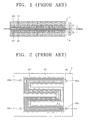
fuel flow hole 143a of FIG. 10 to the MEA. Elements identical to those of FIG. 10 and 11 are indicated using the same reference numerals. - Referring to FIG. 12, a MEA' of a single cell is placed between the
bipolar plates 140. An electrolyte membrane 110' is interposed between an anode 120' and a cathode 130' constituting the MEA'. - Fuel flow holes are formed at each
bipolar plate 140 and the MEA'. A diameter of the fuel flow hole of thebipolar plate 140 is approximately 3 mm, and a diameter of the corresponding holes 190' of the MEA' is approximately 8 mm. An inner wall of the MEA' hole is coated with a sealingmember 149c, such as silicon glue, to prevent alcohol fuel from leaking into the electrolyte membrane 110' and thecathode 130. Thus, a performance degradation and useless consumption of fuel is prevented. To deposit the sealingmember 149c, firstly, a liquid sealing material is deposited round the fuel flow holes of abipolar plate 140 using an automatic dispenser. Next, MEA' and thebipolar plate 140 are assembled by disposing the liquid sealing material inside an inner surface of hole of MEA'. - FIG. 13 is a plan view of a
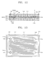
bipolar plate 140 according to another embodiment of the present invention. The same reference numerals as in FIG. 8 are used to the same elements. - Referring to FIG. 13, a
rectangular electrode region 147 where the MEA will be placed and agroove 148 enclosing theelectrode region 147 are formed on thebipolar plate 140. - A plurality of
fuel channels 141 having a serpentine shape exposing from a surface of thebipolar plate 140 are formed with a predetermined depth at theelectrode region 147. Also,fuel flow holes fuel channels 141 through thebipolar plate 140. -
Grooves 150 with a predetermined depth are formed around thefuel flow holes fuel channels 141 on the part of thebipolar plate 140. Thesegrooves 150 are coated with a sealing member to prevent thefuel flow holes - A polymer impregnated graphite block having dimensions of 75 mm W width x 50 mm L length x 1 mm D depth is prepared. Fuel channels are formed on both faces of the block, and fuel flow holes connecting to the fuel channel are formed perforating the block as depicted in FIG. 8. A groove enclosing the rectangular electrode region is formed, and then the groove is coated with liquid silicon using an automatic dispenser. FIG. 9 is a photo of a bipolar plate manufactured in this way.
-
Fuel holes electrolyte membrane 110 having a thickness of 120 µm, and an anode and a cathode having a thickness of 250 µm, respectively. A diameter of thefuel hole 192 of theelectrolyte membrane 110 is 5 mm, a diameter of the hole of afirst electrode hole 191, where fuel is supplied from thefuel flow holes second hole 193, where fuel is not supplied from thefuel flow holes electrodes electrolyte membrane 110 are formed vertically aligning thefuel flow holes - Next, at a surrounding of the two fuel flow holes of the MEA, liquid silicon is deposited on inner surfaces of the electrolyte membrane hole having the diameter of 5 mm and the second electrode having the diameter of 8 mm using an automatic dispenser. FIG. 14 is a photo of the MEA coated around fuel flow holes with liquid silicon. Each MEA coated with liquid silicon around the fuel flow holes is inserted between the thirteen bipolar plates in which the
groove 148 is coated with liquid silicon. Afterward,end plates bipolar plates 140 are placed on and under the stack. Finally, a fuel cell stack is manufactured by compressing the stack using screws. - A sealing test of the manufactured fuel cell stack was performed by pumping methanol [at 1.5 bar] through the fuel supply hole, and air [at 1.5 bar] through the air supply hole, but no leakage was observed.
- A direct liquid feed fuel cell stack according to the present invention has no fuel leakage problem because fuel flow holes are located in an electrode region and the manifold regions between the fuel flow holes to the fuel channels are covered by an electrode, and has no useless fuel consumption. A thin fuel cell stack is manufactured using a bipolar plate having a thickness of 1~2 mm.
- While this invention has been particularly shown and described with reference to preferred embodiments thereof, it will be understood by those skilled in the art that various changes in form and details may be made therein without departing from the scope of the invention as defined by the appended claims.
Claims (12)
- A direct liquid feed fuel cell stack comprising a plurality of stacked bipolar plates having membrane electrode assemblies arranged therebetween, wherein each membrane electrode assembly comprises an electrolyte membrane and an anode and a cathode on respective faces of the electrolyte membrane, and wherein the bipolar plate comprises:a groove enclosing an electrode region where the membrane electrode assembly is disposed on each face of the bipolar plate;a plurality of fuel flow holes to supply fuel or oxidant to corresponding fuel channels at the electrode region of the bipolar plate; anda sealing member formed on the groove.
- The direct liquid feed fuel cell stack of claim 1, wherein the sealing member is formed by depositing a liquid sealing material.
- The direct liquid feed fuel cell stack of claim 1 or 2, wherein
the fuel flow holes connect to other fuel flow holes by a plurality of the fuel channels,
manifolds are formed between the fuel flow holes and the fuel channels, and
the upper part of fuel channels and the manifolds are covered by the anode or the cathode. - The direct liquid feed fuel cell stack of claim 3, wherein grooves are formed around the fuel flow holes not communicating with the fuel channels on each face of the bipolar plate.
- The direct liquid feed fuel cell stack of any one of the preceding claims, wherein uppermost and lowermost bipolar plates have fuel flow channels only on a face that contacts a membrane electrode assembly.
- The direct liquid feed fuel cell stack of any one of the preceding claims, wherein the membrane electrode assembly comprises first and second electrode holes and electrolyte membrane holes corresponding to the locations of the fuel flow holes, wherein
a diameter of the second electrode hole which does not communicate with a corresponding fuel flow hole, is larger than a diameter of the corresponding fuel flow hole, and
a sealing member surrounding the wall of the fuel flow hole is formed on an inner wall of the second electrode hole. - The direct liquid feed fuel cell stack of claim 6, wherein the sealing member is formed by depositing a liquid sealing material on a step, and the step is formed by a diameter difference between the second electrode hole and the electrolyte membrane hole.
- The direct liquid feed fuel cell stack of claim 6, wherein a diameter of the electrolyte membrane hole is bigger than the diameter of the fuel flow hole, wherein the sealing member that surrounds the wall of the fuel flow hole is formed on an inner wall of the second electrode hole and the electrolyte membrane hole.
- The direct liquid feed fuel cell stack of claim 8, wherein a diameter of the electrolyte membrane hole is smaller than the diameter of the second electrode hole.
- The direct liquid feed fuel cell stack of claim 9, wherein the sealing member is formed by depositing a liquid sealing material on a step, and the step is formed by a diameter difference between the second electrode hole, the electrolyte membrane hole, and the first electrode hole.
- The direct liquid feed fuel cell stack of claim 1, wherein the membrane electrode assembly has a plurality of membrane electrode assembly holes corresponding to the locations of the fuel flow holes, the diameter of the membrane electrode assembly holes is bigger than the fuel flow holes of the bipolar plate, and a sealing member is placed on a portion of an inner wall of each membrane electrode assembly hole surrounding the fuel holes.
- The direct liquid feed fuel cell stack of claim 11, wherein the sealing member is formed around the corresponding fuel flow hole of the bipolar plate by depositing a liquid sealing material.
Applications Claiming Priority (2)
| Application Number | Priority Date | Filing Date | Title |
|---|---|---|---|
| KR2003068322 | 2003-10-01 | ||
| KR10-2003-0068322A KR100528339B1 (en) | 2003-10-01 | 2003-10-01 | Direct liquid feed fuel cell stack |
Publications (3)
| Publication Number | Publication Date |
|---|---|
| EP1521322A2 true EP1521322A2 (en) | 2005-04-06 |
| EP1521322A3 EP1521322A3 (en) | 2006-08-02 |
| EP1521322B1 EP1521322B1 (en) | 2008-04-09 |
Family
ID=34309536
Family Applications (1)
| Application Number | Title | Priority Date | Filing Date |
|---|---|---|---|
| EP04252702A Expired - Fee Related EP1521322B1 (en) | 2003-10-01 | 2004-05-10 | Direct liquid feed fuel cell stack |
Country Status (6)
| Country | Link |
|---|---|
| US (1) | US7579101B2 (en) |
| EP (1) | EP1521322B1 (en) |
| JP (1) | JP4519595B2 (en) |
| KR (1) | KR100528339B1 (en) |
| CN (1) | CN100364163C (en) |
| DE (1) | DE602004012940T2 (en) |
Cited By (2)
| Publication number | Priority date | Publication date | Assignee | Title |
|---|---|---|---|---|
| WO2009019421A1 (en) * | 2007-08-03 | 2009-02-12 | Rolls-Royce Plc | A fuel cell and a method of manufacturing a fuel cell |
| CN113839060A (en) * | 2020-06-24 | 2021-12-24 | 未势能源科技有限公司 | Fuel cell unit and fuel cell stack structure |
Families Citing this family (29)
| Publication number | Priority date | Publication date | Assignee | Title |
|---|---|---|---|---|
| JP4562501B2 (en) * | 2004-11-25 | 2010-10-13 | 本田技研工業株式会社 | Fuel cell |
| US20090061271A1 (en) * | 2005-05-11 | 2009-03-05 | Nec Corporation | Fuel cell and a fuel cell system |
| KR100657960B1 (en) | 2005-05-17 | 2006-12-14 | 삼성에스디아이 주식회사 | Fuel cell system and mobile communication device comprising the same |
| KR100708693B1 (en) * | 2005-06-24 | 2007-04-18 | 삼성에스디아이 주식회사 | Direct liquid feed fuel cell stack |
| KR100707161B1 (en) * | 2005-07-16 | 2007-04-13 | 삼성에스디아이 주식회사 | Fuel cartridge and direct liquid feed fuel cell having the same |
| KR100682865B1 (en) * | 2005-10-19 | 2007-02-15 | 삼성에스디아이 주식회사 | Water recovery system and direct liquid feed fuel cell having the same |
| KR101156530B1 (en) * | 2005-11-02 | 2012-06-20 | 삼성에스디아이 주식회사 | Direct liquid feed fuel cell |
| KR100646953B1 (en) * | 2005-11-10 | 2006-11-23 | 삼성에스디아이 주식회사 | Plate type fuel cell system |
| KR100718113B1 (en) * | 2006-01-27 | 2007-05-15 | 삼성에스디아이 주식회사 | Bipolar plate for fuel cell and fuel cell |
| KR100658756B1 (en) | 2006-02-16 | 2006-12-15 | 삼성에스디아이 주식회사 | Membrane-electrode assembly for mixed reactant fuel cell and mixed reactant fuel cell system comprising same |
| KR100709222B1 (en) | 2006-02-20 | 2007-04-18 | 삼성에스디아이 주식회사 | Stack for mixed reactant fuel cell and mixed reactant fuel cell system comprising same |
| JP4489036B2 (en) | 2006-02-28 | 2010-06-23 | 三洋電機株式会社 | Fuel cell stack |
| KR100786480B1 (en) | 2006-11-30 | 2007-12-17 | 삼성에스디아이 주식회사 | Module type fuel cell system |
| KR100811982B1 (en) | 2007-01-17 | 2008-03-10 | 삼성에스디아이 주식회사 | Fuel cell system and control method of it |
| KR100805529B1 (en) * | 2007-02-21 | 2008-02-20 | 삼성에스디아이 주식회사 | Fuel cell stack and fuel cell system |
| KR100869798B1 (en) * | 2007-04-25 | 2008-11-21 | 삼성에스디아이 주식회사 | Stack for fuel cell |
| US20080280167A1 (en) * | 2007-05-08 | 2008-11-13 | American Power Conversion Corporation | Fuel cell stack performance monitoring |
| US20080292936A1 (en) * | 2007-05-23 | 2008-11-27 | American Power Conversion Corporation | Manifold for fuel cells |
| US20090087695A1 (en) * | 2007-10-02 | 2009-04-02 | American Power Conversion Corporation | Bipolar plate for use in fuel cell stacks and fuel cell assemblies |
| CN101414690A (en) | 2007-10-17 | 2009-04-22 | 英属盖曼群岛商胜光科技股份有限公司 | Stack structure for fuel battery |
| KR100981574B1 (en) * | 2008-05-26 | 2010-09-10 | 삼성에스디아이 주식회사 | Separator for fuel cell and fuel cell stack using the same |
| JP5325017B2 (en) * | 2008-08-27 | 2013-10-23 | 日本碍子株式会社 | Solid oxide fuel cell and assembly method thereof |
| KR101063461B1 (en) * | 2008-10-15 | 2011-09-08 | 삼성전기주식회사 | Fuel cell |
| DE102008051742B4 (en) * | 2008-10-15 | 2022-02-24 | Purem GmbH | Fuel cell and fuel cell system |
| GB2505963B (en) * | 2012-09-18 | 2021-04-07 | Intelligent Energy Ltd | A fuel cell stack assembly |
| CN103700801A (en) * | 2013-12-30 | 2014-04-02 | 中国科学院宁波材料技术与工程研究所 | Solid oxide fuel cell stack and cell connector thereof |
| US10273586B2 (en) * | 2014-02-20 | 2019-04-30 | Proton Energy Systems, Inc. | Electrochemical cell |
| CN113113628B (en) * | 2021-03-11 | 2022-10-14 | 东风汽车集团股份有限公司 | Proton exchange membrane fuel cell and fuel cell automobile |
| CN114318386A (en) * | 2022-01-20 | 2022-04-12 | 氢鸿(杭州)科技有限公司 | Proton exchange membrane water electrolyzer, system and method |
Citations (4)
| Publication number | Priority date | Publication date | Assignee | Title |
|---|---|---|---|---|
| DE19718970A1 (en) * | 1997-05-05 | 1998-11-12 | Zsw | Integral PEM fuel cell heating module and its use as well as PEM fuel cell stack |
| US6080503A (en) * | 1997-03-29 | 2000-06-27 | Ballard Power Systems Inc. | Polymer electrolyte membrane fuel cells and stacks with adhesively bonded layers |
| CA2451096A1 (en) * | 2001-07-06 | 2003-01-16 | Honda Giken Kogyo Kabushiki Kaisha | Sealing material coating method for fuel cell-use separator |
| WO2003026049A2 (en) * | 2001-09-18 | 2003-03-27 | Dupont Canada Inc. | Modular fuel cell cartridge and stack |
Family Cites Families (13)
| Publication number | Priority date | Publication date | Assignee | Title |
|---|---|---|---|---|
| JPS62136777A (en) * | 1986-04-04 | 1987-06-19 | Kansai Electric Power Co Inc:The | Cell stack for fuel cell |
| JPH07226220A (en) | 1994-02-08 | 1995-08-22 | Osaka Gas Co Ltd | Fuel cell |
| US5879826A (en) * | 1995-07-05 | 1999-03-09 | Humboldt State University Foundation | Proton exchange membrane fuel cell |
| US6146780A (en) * | 1997-01-24 | 2000-11-14 | Lynntech, Inc. | Bipolar separator plates for electrochemical cell stacks |
| DE19829142A1 (en) * | 1998-06-30 | 2000-01-05 | Manhattan Scientifics Inc | Gas-tight combination of bipolar plate and membrane-electrode assembly of polymer electrolyte membrane fuel cells |
| JP2002313371A (en) | 2000-12-07 | 2002-10-25 | Sanyo Electric Co Ltd | Cell unit of fuel cell |
| JP4223663B2 (en) | 2000-09-06 | 2009-02-12 | 三菱電機株式会社 | Fuel cell |
| KR100397611B1 (en) | 2001-03-31 | 2003-09-17 | 삼성전자주식회사 | Proton exchange fuel cell stack |
| JP2003017093A (en) | 2001-07-03 | 2003-01-17 | Nok Corp | Gasket for fuel cell |
| JP3952139B2 (en) | 2001-11-22 | 2007-08-01 | Nok株式会社 | Fuel cell |
| JP3962899B2 (en) | 2001-12-26 | 2007-08-22 | Nok株式会社 | Sealant for fuel cell |
| JP4585310B2 (en) * | 2002-04-23 | 2010-11-24 | プロトネクス テクノロジー コーポレーション | Membrane electrochemical cell stack |
| US6864004B2 (en) * | 2003-04-03 | 2005-03-08 | The Regents Of The University Of California | Direct methanol fuel cell stack |
-
2003
- 2003-10-01 KR KR10-2003-0068322A patent/KR100528339B1/en not_active IP Right Cessation
-
2004
- 2004-04-26 CN CNB2004100384417A patent/CN100364163C/en not_active Expired - Fee Related
- 2004-05-10 EP EP04252702A patent/EP1521322B1/en not_active Expired - Fee Related
- 2004-05-10 DE DE602004012940T patent/DE602004012940T2/en active Active
- 2004-08-11 US US10/915,567 patent/US7579101B2/en not_active Expired - Fee Related
- 2004-10-01 JP JP2004290367A patent/JP4519595B2/en not_active Expired - Fee Related
Patent Citations (4)
| Publication number | Priority date | Publication date | Assignee | Title |
|---|---|---|---|---|
| US6080503A (en) * | 1997-03-29 | 2000-06-27 | Ballard Power Systems Inc. | Polymer electrolyte membrane fuel cells and stacks with adhesively bonded layers |
| DE19718970A1 (en) * | 1997-05-05 | 1998-11-12 | Zsw | Integral PEM fuel cell heating module and its use as well as PEM fuel cell stack |
| CA2451096A1 (en) * | 2001-07-06 | 2003-01-16 | Honda Giken Kogyo Kabushiki Kaisha | Sealing material coating method for fuel cell-use separator |
| WO2003026049A2 (en) * | 2001-09-18 | 2003-03-27 | Dupont Canada Inc. | Modular fuel cell cartridge and stack |
Cited By (3)
| Publication number | Priority date | Publication date | Assignee | Title |
|---|---|---|---|---|
| WO2009019421A1 (en) * | 2007-08-03 | 2009-02-12 | Rolls-Royce Plc | A fuel cell and a method of manufacturing a fuel cell |
| US8709673B2 (en) | 2007-08-03 | 2014-04-29 | Lg Fuel Cell Systems Inc | Fuel cell and a method of manufacturing a fuel cell |
| CN113839060A (en) * | 2020-06-24 | 2021-12-24 | 未势能源科技有限公司 | Fuel cell unit and fuel cell stack structure |
Also Published As
| Publication number | Publication date |
|---|---|
| DE602004012940T2 (en) | 2009-05-20 |
| JP4519595B2 (en) | 2010-08-04 |
| KR20050032291A (en) | 2005-04-07 |
| KR100528339B1 (en) | 2005-11-15 |
| DE602004012940D1 (en) | 2008-05-21 |
| US20050074652A1 (en) | 2005-04-07 |
| EP1521322B1 (en) | 2008-04-09 |
| JP2005108850A (en) | 2005-04-21 |
| EP1521322A3 (en) | 2006-08-02 |
| CN1604379A (en) | 2005-04-06 |
| CN100364163C (en) | 2008-01-23 |
| US7579101B2 (en) | 2009-08-25 |
Similar Documents
| Publication | Publication Date | Title |
|---|---|---|
| EP1521322B1 (en) | Direct liquid feed fuel cell stack | |
| KR100493153B1 (en) | Air breathing direct methanol fuel cell pack | |
| KR100450820B1 (en) | Air breathing direct methanol fuel cell pack | |
| US6261711B1 (en) | Sealing system for fuel cells | |
| US8216738B2 (en) | Deactivation of SOFC anode substrate for direct internal reforming | |
| US7951506B2 (en) | Bipolar plate and direct liquid feed fuel cell stack | |
| JP4755574B2 (en) | Bipolar plates and fuel cells | |
| US20020119359A1 (en) | Polymer electrolyte fuel cell | |
| US8039171B2 (en) | Current-collecting composite plate for fuel cell and fuel cell fabricated using same | |
| US20110281193A1 (en) | Fuel cell fluid distribution system | |
| US8119306B2 (en) | Bipolar plate and direct liquid feed fuel cell stack | |
| WO2004054011A2 (en) | Gas diffusion layer for an electrochemical cell | |
| JP5062392B2 (en) | Polymer electrolyte fuel cell | |
| US8227136B2 (en) | Using ionomer to militate against membrane buckling in the tenting region | |
| US7160642B2 (en) | Fuel cell stack assembly and method of fabrication | |
| US7914944B2 (en) | Atmosphere open type fuel cell | |
| CN100452514C (en) | Membrane electrode assembly and fuel cell | |
| JP2007087728A (en) | Laminate, method of manufacturing it, as well as fuel cell | |
| CN115275253A (en) | Fuel cell | |
| CN117242208A (en) | Hydropower Jie Dui for producing hydrogen and oxygen from water | |
| US8101316B2 (en) | Solid oxide fuel cell | |
| WO2006068527A2 (en) | Hydrogen- fuel cell stack with integrated cooling and air supply for use with a fixed pressure dead-ended supply configuration | |
| JP2023059529A (en) | Fuel battery | |
| KR100964294B1 (en) | Solid oxide fuel cells with a planar banded array of unit cells | |
| JP2004319389A (en) | Fuel cell system |
Legal Events
| Date | Code | Title | Description |
|---|---|---|---|
| PUAI | Public reference made under article 153(3) epc to a published international application that has entered the european phase |
Free format text: ORIGINAL CODE: 0009012 |
|
| 17P | Request for examination filed |
Effective date: 20040602 |
|
| AK | Designated contracting states |
Kind code of ref document: A2 Designated state(s): AT BE BG CH CY CZ DE DK EE ES FI FR GB GR HU IE IT LI LU MC NL PL PT RO SE SI SK TR |
|
| AX | Request for extension of the european patent |
Extension state: AL HR LT LV MK |
|
| PUAL | Search report despatched |
Free format text: ORIGINAL CODE: 0009013 |
|
| AK | Designated contracting states |
Kind code of ref document: A3 Designated state(s): AT BE BG CH CY CZ DE DK EE ES FI FR GB GR HU IE IT LI LU MC NL PL PT RO SE SI SK TR |
|
| AX | Request for extension of the european patent |
Extension state: AL HR LT LV MK |
|
| AKX | Designation fees paid |
Designated state(s): DE FR GB |
|
| 17Q | First examination report despatched |
Effective date: 20070323 |
|
| GRAP | Despatch of communication of intention to grant a patent |
Free format text: ORIGINAL CODE: EPIDOSNIGR1 |
|
| GRAS | Grant fee paid |
Free format text: ORIGINAL CODE: EPIDOSNIGR3 |
|
| GRAA | (expected) grant |
Free format text: ORIGINAL CODE: 0009210 |
|
| AK | Designated contracting states |
Kind code of ref document: B1 Designated state(s): DE FR GB |
|
| REG | Reference to a national code |
Ref country code: GB Ref legal event code: FG4D |
|
| REF | Corresponds to: |
Ref document number: 602004012940 Country of ref document: DE Date of ref document: 20080521 Kind code of ref document: P |
|
| ET | Fr: translation filed | ||
| PLBE | No opposition filed within time limit |
Free format text: ORIGINAL CODE: 0009261 |
|
| STAA | Information on the status of an ep patent application or granted ep patent |
Free format text: STATUS: NO OPPOSITION FILED WITHIN TIME LIMIT |
|
| 26N | No opposition filed |
Effective date: 20090112 |
|
| REG | Reference to a national code |
Ref country code: FR Ref legal event code: PLFP Year of fee payment: 12 |
|
| PGFP | Annual fee paid to national office [announced via postgrant information from national office to epo] |
Ref country code: GB Payment date: 20150410 Year of fee payment: 12 Ref country code: DE Payment date: 20150409 Year of fee payment: 12 |
|
| PGFP | Annual fee paid to national office [announced via postgrant information from national office to epo] |
Ref country code: FR Payment date: 20150413 Year of fee payment: 12 |
|
| REG | Reference to a national code |
Ref country code: DE Ref legal event code: R119 Ref document number: 602004012940 Country of ref document: DE |
|
| GBPC | Gb: european patent ceased through non-payment of renewal fee |
Effective date: 20160510 |
|
| REG | Reference to a national code |
Ref country code: FR Ref legal event code: ST Effective date: 20170131 |
|
| PG25 | Lapsed in a contracting state [announced via postgrant information from national office to epo] |
Ref country code: FR Free format text: LAPSE BECAUSE OF NON-PAYMENT OF DUE FEES Effective date: 20160531 Ref country code: DE Free format text: LAPSE BECAUSE OF NON-PAYMENT OF DUE FEES Effective date: 20161201 |
|
| PG25 | Lapsed in a contracting state [announced via postgrant information from national office to epo] |
Ref country code: GB Free format text: LAPSE BECAUSE OF NON-PAYMENT OF DUE FEES Effective date: 20160510 |