EP1520556B1 - Fluid containing endoluminal stent - Google Patents
Fluid containing endoluminal stent Download PDFInfo
- Publication number
- EP1520556B1 EP1520556B1 EP04029223A EP04029223A EP1520556B1 EP 1520556 B1 EP1520556 B1 EP 1520556B1 EP 04029223 A EP04029223 A EP 04029223A EP 04029223 A EP04029223 A EP 04029223A EP 1520556 B1 EP1520556 B1 EP 1520556B1
- Authority
- EP
- European Patent Office
- Prior art keywords
- stent
- fluid
- core
- catheter
- endoluminal
- Prior art date
- Legal status (The legal status is an assumption and is not a legal conclusion. Google has not performed a legal analysis and makes no representation as to the accuracy of the status listed.)
- Expired - Lifetime
Links
Images


Classifications
-
- A—HUMAN NECESSITIES
- A61—MEDICAL OR VETERINARY SCIENCE; HYGIENE
- A61F—FILTERS IMPLANTABLE INTO BLOOD VESSELS; PROSTHESES; DEVICES PROVIDING PATENCY TO, OR PREVENTING COLLAPSING OF, TUBULAR STRUCTURES OF THE BODY, e.g. STENTS; ORTHOPAEDIC, NURSING OR CONTRACEPTIVE DEVICES; FOMENTATION; TREATMENT OR PROTECTION OF EYES OR EARS; BANDAGES, DRESSINGS OR ABSORBENT PADS; FIRST-AID KITS
- A61F2/00—Filters implantable into blood vessels; Prostheses, i.e. artificial substitutes or replacements for parts of the body; Appliances for connecting them with the body; Devices providing patency to, or preventing collapsing of, tubular structures of the body, e.g. stents
- A61F2/82—Devices providing patency to, or preventing collapsing of, tubular structures of the body, e.g. stents
- A61F2/86—Stents in a form characterised by the wire-like elements; Stents in the form characterised by a net-like or mesh-like structure
- A61F2/88—Stents in a form characterised by the wire-like elements; Stents in the form characterised by a net-like or mesh-like structure the wire-like elements formed as helical or spiral coils
-
- A—HUMAN NECESSITIES
- A61—MEDICAL OR VETERINARY SCIENCE; HYGIENE
- A61F—FILTERS IMPLANTABLE INTO BLOOD VESSELS; PROSTHESES; DEVICES PROVIDING PATENCY TO, OR PREVENTING COLLAPSING OF, TUBULAR STRUCTURES OF THE BODY, e.g. STENTS; ORTHOPAEDIC, NURSING OR CONTRACEPTIVE DEVICES; FOMENTATION; TREATMENT OR PROTECTION OF EYES OR EARS; BANDAGES, DRESSINGS OR ABSORBENT PADS; FIRST-AID KITS
- A61F2210/00—Particular material properties of prostheses classified in groups A61F2/00 - A61F2/26 or A61F2/82 or A61F9/00 or A61F11/00 or subgroups thereof
- A61F2210/0014—Particular material properties of prostheses classified in groups A61F2/00 - A61F2/26 or A61F2/82 or A61F9/00 or A61F11/00 or subgroups thereof using shape memory or superelastic materials, e.g. nitinol
- A61F2210/0023—Particular material properties of prostheses classified in groups A61F2/00 - A61F2/26 or A61F2/82 or A61F9/00 or A61F11/00 or subgroups thereof using shape memory or superelastic materials, e.g. nitinol operated at different temperatures whilst inside or touching the human body, heated or cooled by external energy source or cold supply
- A61F2210/0042—Particular material properties of prostheses classified in groups A61F2/00 - A61F2/26 or A61F2/82 or A61F9/00 or A61F11/00 or subgroups thereof using shape memory or superelastic materials, e.g. nitinol operated at different temperatures whilst inside or touching the human body, heated or cooled by external energy source or cold supply using a fluid, e.g. circulating
-
- A—HUMAN NECESSITIES
- A61—MEDICAL OR VETERINARY SCIENCE; HYGIENE
- A61F—FILTERS IMPLANTABLE INTO BLOOD VESSELS; PROSTHESES; DEVICES PROVIDING PATENCY TO, OR PREVENTING COLLAPSING OF, TUBULAR STRUCTURES OF THE BODY, e.g. STENTS; ORTHOPAEDIC, NURSING OR CONTRACEPTIVE DEVICES; FOMENTATION; TREATMENT OR PROTECTION OF EYES OR EARS; BANDAGES, DRESSINGS OR ABSORBENT PADS; FIRST-AID KITS
- A61F2250/00—Special features of prostheses classified in groups A61F2/00 - A61F2/26 or A61F2/82 or A61F9/00 or A61F11/00 or subgroups thereof
- A61F2250/0058—Additional features; Implant or prostheses properties not otherwise provided for
- A61F2250/0067—Means for introducing or releasing pharmaceutical products into the body
Definitions
- the present invention relates to an endoluminal stent.
- Stents and similar endoluminal devices have been used to expand a constricted vessel to maintain an open passageway through the vessel in many medical situations, for example, following angioplasty of a coronary artery.
- stents are useful to prevent restenosis of the dilated vessel through proliferation of vascular tissues.
- Stents can also be used to reinforce collapsing structures in the respiratory system, the reproductive system, biliary ducts or any tubular body lumens. Whereas in vascular applications fatty deposits or "plaque" frequently cause the stenosis, in many other body lumens the narrowing or closing may be caused by malignant tissue.
- Fluids have traditionally been used to pressurize the angioplasty balloons used to open restricted vessels.
- the balloons may have a variety of shapes including a coiled form.
- fluid is injected into the balloon to inflate the device and maintain turgidity.
- Shturman U.S. Patent No. 5,181,911 discloses a perfusion balloon catheter wound into a helically coiled shape with one end attached to a fitting and the other to a syringe for inflating the balloon with fluid.
- the balloon When the balloon is inflated, its coiled form allows blood flow thorough the open center of the structure.
- the syringe can deliver fluid into the balloon, fluid can flow through the balloon, and fluid can then exit through a second lumen in a catheter attached to the syringe.
- Coiled stents that are connected to a catheter apparatus, as in Wang et al. ( U.S. Pat. No. 5,795,318 ), are used for temporary insertion into a patient.
- Wang et al. discloses a coiled stent of shape-memory thermoplastic tube that can be converted from a relatively narrow diameter to a larger coiled form by heating.
- the narrow diameter coil is mounted at the end of a catheter over a balloon and in a preferred embodiment a resistive heating element runs down the length of the thermoplastic element.
- An electric current is applied to heat the element thereby softening it while the balloon is expanded to enlarge the diameter of the coil.
- the temporary stent has performed its duty, it is again heated and removed while in the softened state.
- the thermoplastic tube is supplied with an additional lumen so that liquid drugs can flow into the stent and delivered through apertures or semipermeable regions.
- Prior art coil stents are known from US 5,370,691 A , WO 98/23228 A1 , and WO 96/26682 A1 .
- an endoluminal stent comprising: an elongate stent core; a plastic cover fitted over and extending along the core and spaced apart from the core ; a hollow passageway defined within the plastic cover along the stent core through which fluid can flow, the stent core and plastic cover being formed into a coil; and connector means for releasably establishing communication between a source and the passageway.
- Such a stent may be an endoluminal coil stent comprising a hollow tube formed into a series of loops or other known stent shapes which initially has a low profile and diameter.
- This structure can be delivered into a patient's vascular system and expanded to full size.
- the stent is hollow allowing the passage of fluid.
- the stent has either one or a plurality of passageways for fluid flow.
- the stent is attachable to a catheter via a special fitting so that when engaged with the catheter, fluid flows freely from the catheter to the stent with a possible return circuit through the catheter. When disengaged, the fitting prevents leakage from the stent permitting the stent to remain in place in a patient's vasculature.
- the stent provides for a way of treating vascular areas affected with malignant growths or experiencing restenosis from smooth muscle cell proliferation, etc.
- the stent is inserted in a small diameter configuration and, after being enlarged to a larger diameter, acts as a support device for the areas of restenosis or malignant growth.
- the stent can treat these affected areas in a unique way by flowing radioactive, heated or cryogenic fluids through the stent.
- a stent to accomplish this purpose can be composed of several different materials.
- the stent can be formed from a metal or other material with small pores machined or otherwise formed (e.g., with a laser).
- a stent is filed with a drug, that drug slowly disperses through the pores.
- an entire metal tube or portions of the tube could be formed e.g. from sintered metal powder thereby forming a porous structure for drug delivery.
- Another embodiment would alternate a metal tube (for structural stability) with dispensing segments inserted at various intervals. The segments would be perforated to allow seepage of the drug or would be otherwise formed from a porous material.
- Another embodiment employs an expanded polytetrafluoroethylene (PTFE) tube around a support wire or metal tube in the form of a coiled stent so that a hollow passageway is created between the metal and the PTFE. A drug is flowed into this space and slowly dispensed through the porous PTFE.
- PTFE polytetrafluoroethylene
- One embodiment of the hollow stent comprises a shape memory metal such as nitinol.
- Shape memory metals are a group of metallic compositions that have the ability to return to a defined shape or size when subjected to certain thermal or stress conditions. Shape memory metals are generally capable of being deformed at a relatively low temperature and, upon exposure to a relatively higher temperature, return to the defined shape or size they held prior to the deformation. This enables the stent to be inserted into the body in a deformed, smaller state so that it assumes its "remembered" larger shape once it is exposed to a higher temperature (i.e. body temperature or heated fluid) in vivo.
- a higher temperature i.e. body temperature or heated fluid
- the hollow stent has an inlet and an outlet so that a complete fluid path can be created, and fluid can be continually circulated through the stent.
- the inlet and outlet are at opposite ends of the stent.
- two lumens can be connected at a distal end of the structure so that the outlet and inlet are both together at one end.
- Other arrangements can be readily envisioned by one of ordinary skill in the art.
- the stent is configured to be inserted into the body while connected to a catheter in a small, deformed state. Once inside the patient's body the stent is advanced to a desired position and expanded to its larger full size. If the stent is a composed of shape memory metal, for example, the stent expands from its small-deformed state to its remembered larger state due to the higher body temperature or due to the passage of "hot" fluid through the stent. Subsequently "treatment” fluid (e.g., heated, cryogenic or radioactive) is pumped through the catheter to the stent where it is circulated throughout the stent, treating the adjacent vascular walls. The catheter can either be left in place for a certain period of time or removed, leaving the fluid inside the stent. This would particularly be the case with radioactive fluid or with a porous drug delivery stent.
- treatment fluid e.g., heated, cryogenic or radioactive
- the stent can be removed by reattaching the catheter allowing one to chill and shrink the stent (in the case of a memory alloy).
- the device can readily be used in its tethered form to remove memory alloy stents of the present invention or of prior art design.
- a device of the present invention is inserted into the vasculature to rest within the stent to be removed. Warm fluid is then circulated causing the stent to expand into contact with the memory alloy stent that is already in position. At this point cryogenic (e.g., low temperature) fluid is circulated causing the attached stent and the contacted stent to shrink so that the combination can be readily withdrawn.
- FIG. 1 depicts a stent embodiment useful to help understanding of this invention.
- Pictured in FIG. 1 is a medical apparatus 10 comprising an endoluminal stent 20 attached to a delivery catheter 30 by means of a valve assembly 40.
- endoluminal stent 20 is generally coiled in shape leaving a tubular space down the center of its length.
- the tubing 22 of the stent 20 is preferably composed of a metal material that can be crimped onto a balloon catheter (not shown) for insertion into a body. Once positioned inside of the body at the desired location, the balloon can be inflated, bringing the stent from a compact small size to its enlarged full size thus opening a pathway for blood flow.
- the valve assembly 40 has small hollow needles 48 that are designed to puncture elastomer diaphragms 25.
- the catheter 30 is slightly larger in diameter than the stent member 20 so that the catheter tubing wall 32 forms a friction fit over the stent wall 22. This creates a seal between the catheter 30 and the stent 20 for fluid delivery and removal. Upon detaching the catheter 30 leakage from the stent 20 is prevented due to the self-healing properties of the diaphragms 25.
- the back flow preventer 40 could be on the stent 20 and the diaphragms be on the catheter 30.
- stent 20 is inserted into the body to the desired site through the use of a catheter insertion device well known in the art.
- FIG. 4 depicts stent 20 in its enlarged form after it has been inserted into the body at the affected location and expanded.
- Other means of stent expansion other than a balloon catheter are possible.
- the stent 20 is formed from shape memory metal, such as nitinol, the heat of the body can cause the stent 20 to assume a larger, remembered form. Alternatively, heated fluid can be circulated through the stent to cause it to recover its remembered form.
- a self-expanding stent made of a spring-type alloy can also be employed. In that case the delivery catheter would be equipped with means (e.g., an outer sheath) to keep the stent compressed until it was at the desired location.
- the passageway is enlarged to permit increased blood flow.
- fluids can also pass through the interior of tubes 22 the hollow stent 20 to treat the vascular wall.
- the walls of the vasculature can be treated by running either a radioactive fluid through the stent 20 or a heated or a cryogenic liquid or a drug with a stent equipped for drug diffusion (e.g., through holes or a porous region).
- FIG. 5 depicts a second embodiment useful for understanding of the invention.
- the hollow stent 60 has only one fluid pathway 66, an inlet without an outlet, and is used to deliver drugs to affected areas. Once the stent 60 is inserted into place and is in its enlarged configuration, drugs are delivered through the catheter to the stent 60.
- Stent 60 can be constructed in various ways to facilitate the delivery of drugs. In one case, as shown in FIG. 6 , the stent 60 is constructed with regions or segments that have pores 64 to allow drug seepage from the tubing 62. Alternatively, continuously porous metal, porous plastic, or a combination of metal and plastic can be used.
- the perforations 64 or slits in the stent to facilitate drug delivery must be of sufficiently small size to allow the passage of the drug through the entire length of the stent so that all areas can be treated. It will be apparent that pore size can control the rate at which the drug is dispensed. It is possible to cover the pores 64 with semipermeable membrane to further control and restrict drug outflow. A semipermeable membrane with inclusion of an osmotic agent with the drug will result in water uptake and more rapid and controlled pressurized delivery of the drug.
- a third embodiment useful for understanding of the invention has a hollow stent 70 containing a single fluid pathway.
- the tubing 72 can be made of any of the materials discussed above, but in this embodiment, the stent 70 has an inlet path 78 that carries the fluid to the distal end 74 of stent 70 where it then runs through the coils.
- a valve 80 connects the stent 70 to catheter 30.
- FIG. 8 shows a cross-sectional view of valve 80. The pressure from the liquid sent through the catheter causes the gate 82 of valve 80 to open to allow the fluid into the inlet path 78.
- the pressure that forces the opening of gate 82 causes the simultaneous opening of gate 84, allowing the fluid that is circulated through the stent 70 to exit through pathway 36 of catheter 30.
- the fluid entering and exiting through catheter 30 must also go through a check ball valve assembly similar to the one shown in FIG. 2 . Again, flaps or other "one way" valve mechanisms can be applied. After all incoming fluid has been delivered to the stent 70, the absence of pressure causes gate 82 and gate 84 to close, thereby closing valve 80.
- This design can be used with any of the fluids mentioned above.
- the stent 70 can be used to circulate radioactive or cryogenic fluids for treatment of the vascular walls and can also be perforated for the delivery of drugs.
- a hollow coiled stent 90 is formed from polytetrafluoroethylene (PTFE) 92.
- PTFE polytetrafluoroethylene
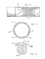
- FIG. 9 a perspective view of this embodiment can be seen.
- the stent 90 consists of a support wire 94 over which PTFE 92 is fitted. The pliable structure resulting is then formed into a coiled stent.
- the PTFE 92 is fitted around the wire 94 so that there is sufficient room to allow the passage of fluid.
- FIG. 10 shows a cross-sectional view of stent 90, illustrating the pathway 96 created around the support wire 94 to allow the passage of fluid.
- stretched expanded PTFE can be used to create a porous stent to facilitate the delivery of drugs.
- the wire 94 can also be hollow (passageway 95) so that the stent 90 can simultaneously deliver drugs and radioactive fluid or temperature regulating fluid.
- FIG. 12 A flow diagram for a method of providing treatment with a coiled hollow stent is shown in Fig. 12 .
- This is a method for recapturing an existing shape memory metal stent already in the body.
- a shape memory metal stent A is inserted into the body in its small, deformed state through the use of an insertion device 112 well known in the art.
- the inserted stent A in its deformed state is placed into the center of a memory alloy stent B that is already in an enlarged support position in the body 114.
- the deformed stent A is then enlarged so that it comes in contact with stent B. This can be accomplished in one of two ways.
- stent A may enlarge due to the higher in vivo body temperature 115, or a hot liquid is pumped through stent A to cause it to expand 116.
- cryogenic liquid is pumped through stent A so that both stent A and stent B are chilled and either shrink down to their deformed states or become sufficiently relaxed to allow ready removal 118.
- stents A and B are easily removed from the body 119 by withdrawing the catheter attached to slent A.
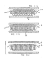
- Fig. 11a illustrates stent A in its reduced state being inserted into stent B.
- Fig. 11b shows an enlarged version of stent A contacting stent B. Thereafter, a temperature change caused by fluid circulating through stent A will shrink both stents and enable their removal ( Fig. 11c ).
Description
- The present invention relates to an endoluminal stent.
- Stents and similar endoluminal devices have been used to expand a constricted vessel to maintain an open passageway through the vessel in many medical situations, for example, following angioplasty of a coronary artery. In these situations, stents are useful to prevent restenosis of the dilated vessel through proliferation of vascular tissues. Stents can also be used to reinforce collapsing structures in the respiratory system, the reproductive system, biliary ducts or any tubular body lumens. Whereas in vascular applications fatty deposits or "plaque" frequently cause the stenosis, in many other body lumens the narrowing or closing may be caused by malignant tissue.
- Fluids have traditionally been used to pressurize the angioplasty balloons used to open restricted vessels. The balloons may have a variety of shapes including a coiled form. In such a device fluid is injected into the balloon to inflate the device and maintain turgidity. Shturman (
U.S. Patent No. 5,181,911 ) discloses a perfusion balloon catheter wound into a helically coiled shape with one end attached to a fitting and the other to a syringe for inflating the balloon with fluid. When the balloon is inflated, its coiled form allows blood flow thorough the open center of the structure. At the same time it is possible to actually have fluid flow within the balloon structure so that the syringe can deliver fluid into the balloon, fluid can flow through the balloon, and fluid can then exit through a second lumen in a catheter attached to the syringe. - Coiled stents that are connected to a catheter apparatus, as in Wang et al. (
U.S. Pat. No. 5,795,318 ), are used for temporary insertion into a patient. Wang et al. discloses a coiled stent of shape-memory thermoplastic tube that can be converted from a relatively narrow diameter to a larger coiled form by heating. The narrow diameter coil is mounted at the end of a catheter over a balloon and in a preferred embodiment a resistive heating element runs down the length of the thermoplastic element. An electric current is applied to heat the element thereby softening it while the balloon is expanded to enlarge the diameter of the coil. Upon cooling the enlarged coil hardens and the balloon is withdrawn. After the temporary stent has performed its duty, it is again heated and removed while in the softened state. In one embodiment the thermoplastic tube is supplied with an additional lumen so that liquid drugs can flow into the stent and delivered through apertures or semipermeable regions. - The attempt to kill or prevent proliferation cells is a common theme in clinical practice. This is generally true in vascular and non-vascular lumens. It is known that ionizing radiation can prevent restenosis and malignant growth. Although the effect of temperature extremes, e.g., cryogenic (cold) or hot temperatures, on cellular activity is not as well researched, it may provide a safer approach to control of tissue proliferation. Among the drawbacks of the prior art coiled balloons is that the balloon material is relatively weak so that expansion and contraction cause the balloon to fail. Failure of a balloon containing radioactive or cryogenic fluids could be catastrophic. It would be desirable to provide a catheter based, minimally invasive device for stenting support that could deliver hot or cryogenic or radioactive fluids or drugs and that would be sturdy and could remain in the body for extended periods of time, detached from the insertion device.
-
- According to a first aspect of the present invention, there is provided an endoluminal stent comprising: an elongate stent core; a plastic cover fitted over and extending along the core and spaced apart from the core ; a hollow passageway defined within the plastic cover along the stent core through which fluid can flow, the stent core and plastic cover being formed into a coil; and connector means for releasably establishing communication between a source and the passageway.
- Such a stent may be an endoluminal coil stent comprising a hollow tube formed into a series of loops or other known stent shapes which initially has a low profile and diameter. This structure can be delivered into a patient's vascular system and expanded to full size. The stent is hollow allowing the passage of fluid. The stent has either one or a plurality of passageways for fluid flow. The stent is attachable to a catheter via a special fitting so that when engaged with the catheter, fluid flows freely from the catheter to the stent with a possible return circuit through the catheter. When disengaged, the fitting prevents leakage from the stent permitting the stent to remain in place in a patient's vasculature.
- The stent provides for a way of treating vascular areas affected with malignant growths or experiencing restenosis from smooth muscle cell proliferation, etc. The stent is inserted in a small diameter configuration and, after being enlarged to a larger diameter, acts as a support device for the areas of restenosis or malignant growth. In addition, the stent can treat these affected areas in a unique way by flowing radioactive, heated or cryogenic fluids through the stent.
- It is described how the steel may also provide a way of delivering drugs to an affected site. A stent to accomplish this purpose can be composed of several different materials. For example, the stent can be formed from a metal or other material with small pores machined or otherwise formed (e.g., with a laser). When such a stent is filed with a drug, that drug slowly disperses through the pores. Alternatively, an entire metal tube or portions of the tube could be formed e.g. from sintered metal powder thereby forming a porous structure for drug delivery. Another embodiment would alternate a metal tube (for structural stability) with dispensing segments inserted at various intervals. The segments would be perforated to allow seepage of the drug or would be otherwise formed from a porous material. Another embodiment employs an expanded polytetrafluoroethylene (PTFE) tube around a support wire or metal tube in the form of a coiled stent so that a hollow passageway is created between the metal and the PTFE. A drug is flowed into this space and slowly dispensed through the porous PTFE.
- One embodiment of the hollow stent comprises a shape memory metal such as nitinol. Shape memory metals are a group of metallic compositions that have the ability to return to a defined shape or size when subjected to certain thermal or stress conditions. Shape memory metals are generally capable of being deformed at a relatively low temperature and, upon exposure to a relatively higher temperature, return to the defined shape or size they held prior to the deformation. This enables the stent to be inserted into the body in a deformed, smaller state so that it assumes its "remembered" larger shape once it is exposed to a higher temperature (i.e. body temperature or heated fluid) in vivo.
- Special fittings are incorporated at the ends of the hollow stent. These fittings facilitate the injection and removal of fluid and also allow the stent to be detached from the insertion device to allow it to be left in place in a patient. The hollow stent has an inlet and an outlet so that a complete fluid path can be created, and fluid can be continually circulated through the stent. In the simplest configuration the inlet and outlet are at opposite ends of the stent. However, if the stent is equipped with a plurality of lumens, two lumens can be connected at a distal end of the structure so that the outlet and inlet are both together at one end. Other arrangements can be readily envisioned by one of ordinary skill in the art.
- The stent is configured to be inserted into the body while connected to a catheter in a small, deformed state. Once inside the patient's body the stent is advanced to a desired position and expanded to its larger full size. If the stent is a composed of shape memory metal, for example, the stent expands from its small-deformed state to its remembered larger state due to the higher body temperature or due to the passage of "hot" fluid through the stent. Subsequently "treatment" fluid (e.g., heated, cryogenic or radioactive) is pumped through the catheter to the stent where it is circulated throughout the stent, treating the adjacent vascular walls. The catheter can either be left in place for a certain period of time or removed, leaving the fluid inside the stent. This would particularly be the case with radioactive fluid or with a porous drug delivery stent.
- The stent can be removed by reattaching the catheter allowing one to chill and shrink the stent (in the case of a memory alloy). Alternatively, the device can readily be used in its tethered form to remove memory alloy stents of the present invention or of prior art design. For this purpose a device of the present invention is inserted into the vasculature to rest within the stent to be removed. Warm fluid is then circulated causing the stent to expand into contact with the memory alloy stent that is already in position. At this point cryogenic (e.g., low temperature) fluid is circulated causing the attached stent and the contacted stent to shrink so that the combination can be readily withdrawn.
- To enable a better understanding of the present invention, and to show how the same may be carried into effect, reference will now be made, by way of example only, to the accompanying drawings, in which:
-
FIG. 1 is a perspective view of a hollow coiled stent comparative example; -
FIG. 2 is a perspective view of a valve assembly to be used with the stent ofFIG 1 ; -
FIG. 3 is a sectional view of the hollow stent tube ofFIG 2 ; -
FIG. 4 is a representation of the stent ofFIG 1 in the position for treatment; -
FIG. 5 is a sectional view of a second comparative example of a hollow coiled stent; -
FIG. 6 is a perspective view of the second comparative example of a hollow coiled stent; -
FIG. 7 is a perspective view of a third comparative example of a hollow coiled stent; -
FIG. 8 is a perspective view of a valve assembly to be used with the stent ofFIG. 6 ; -
FIG. 9 is a perspective view of an embodiment of a hollow coiled stent forming part of the invention; -
FIG. 10 is a sectional view of the hollow stent tube ofFIG. 9 ; -
FIG. 11 (11A, 11B, and 11C) is an illustration of the main steps of the method detailed inFIG. 12 ; and -
FIG. 12 is a flow diagram explaining use of a hollow coiled stent to retrieve a shape memory stent already in place. - Referring now to the drawings, in which like reference numbers represent similar or identical structures throughout the drawings,
FIG. 1 depicts a stent embodiment useful to help understanding of this invention. Pictured inFIG. 1 is amedical apparatus 10 comprising anendoluminal stent 20 attached to adelivery catheter 30 by means of avalve assembly 40. In this representation endoluminalstent 20 is generally coiled in shape leaving a tubular space down the center of its length. Obviously, the principle of a hollow stent can be applied to stents of a zigzag or other construction other than simply coiled. Thetubing 22 of thestent 20 is preferably composed of a metal material that can be crimped onto a balloon catheter (not shown) for insertion into a body. Once positioned inside of the body at the desired location, the balloon can be inflated, bringing the stent from a compact small size to its enlarged full size thus opening a pathway for blood flow. - Inside the
tubing 22 ofstent 20, two fluid pathways exist. These twofluid pathways FIG. 2 . At the distal end ofcatheter 30, thevalve assembly 40 has smallhollow needles 48 that are designed to punctureelastomer diaphragms 25. Thecatheter 30 is slightly larger in diameter than thestent member 20 so that thecatheter tubing wall 32 forms a friction fit over thestent wall 22. This creates a seal between thecatheter 30 and thestent 20 for fluid delivery and removal. Upon detaching thecatheter 30 leakage from thestent 20 is prevented due to the self-healing properties of thediaphragms 25. Obviously, theback flow preventer 40 could be on thestent 20 and the diaphragms be on thecatheter 30. - As discussed above,
stent 20 is inserted into the body to the desired site through the use of a catheter insertion device well known in the art.FIG. 4 depictsstent 20 in its enlarged form after it has been inserted into the body at the affected location and expanded. Other means of stent expansion other than a balloon catheter are possible. If thestent 20 is formed from shape memory metal, such as nitinol, the heat of the body can cause thestent 20 to assume a larger, remembered form. Alternatively, heated fluid can be circulated through the stent to cause it to recover its remembered form. A self-expanding stent made of a spring-type alloy can also be employed. In that case the delivery catheter would be equipped with means (e.g., an outer sheath) to keep the stent compressed until it was at the desired location. - By increasing the diameter of
stent 20 at an affected location, the passageway is enlarged to permit increased blood flow. At the same time, fluids can also pass through the interior oftubes 22 thehollow stent 20 to treat the vascular wall. The walls of the vasculature can be treated by running either a radioactive fluid through thestent 20 or a heated or a cryogenic liquid or a drug with a stent equipped for drug diffusion (e.g., through holes or a porous region). -
FIG. 5 depicts a second embodiment useful for understanding of the invention. In this embodiment, thehollow stent 60 has only onefluid pathway 66, an inlet without an outlet, and is used to deliver drugs to affected areas. Once thestent 60 is inserted into place and is in its enlarged configuration, drugs are delivered through the catheter to thestent 60.Stent 60 can be constructed in various ways to facilitate the delivery of drugs. In one case, as shown inFIG. 6 , thestent 60 is constructed with regions or segments that havepores 64 to allow drug seepage from thetubing 62. Alternatively, continuously porous metal, porous plastic, or a combination of metal and plastic can be used. Theperforations 64 or slits in the stent to facilitate drug delivery must be of sufficiently small size to allow the passage of the drug through the entire length of the stent so that all areas can be treated. It will be apparent that pore size can control the rate at which the drug is dispensed. It is possible to cover thepores 64 with semipermeable membrane to further control and restrict drug outflow. A semipermeable membrane with inclusion of an osmotic agent with the drug will result in water uptake and more rapid and controlled pressurized delivery of the drug. - A third embodiment useful for understanding of the invention, as shown in
FIG. 7 , has ahollow stent 70 containing a single fluid pathway. Thetubing 72 can be made of any of the materials discussed above, but in this embodiment, thestent 70 has aninlet path 78 that carries the fluid to thedistal end 74 ofstent 70 where it then runs through the coils. In this embodiment, avalve 80 connects thestent 70 tocatheter 30.FIG. 8 shows a cross-sectional view ofvalve 80. The pressure from the liquid sent through the catheter causes thegate 82 ofvalve 80 to open to allow the fluid into theinlet path 78. The pressure that forces the opening ofgate 82 causes the simultaneous opening ofgate 84, allowing the fluid that is circulated through thestent 70 to exit throughpathway 36 ofcatheter 30. The fluid entering and exiting throughcatheter 30 must also go through a check ball valve assembly similar to the one shown inFIG. 2 . Again, flaps or other "one way" valve mechanisms can be applied. After all incoming fluid has been delivered to thestent 70, the absence of pressure causesgate 82 andgate 84 to close, thereby closingvalve 80. This design can be used with any of the fluids mentioned above. Thestent 70 can be used to circulate radioactive or cryogenic fluids for treatment of the vascular walls and can also be perforated for the delivery of drugs. - In a fourth embodiment falling within the scope of Claim 1, a hollow
coiled stent 90 is formed from polytetrafluoroethylene (PTFE) 92. InFIG. 9 , a perspective view of this embodiment can be seen. Thestent 90 consists of asupport wire 94 over whichPTFE 92 is fitted. The pliable structure resulting is then formed into a coiled stent. ThePTFE 92 is fitted around thewire 94 so that there is sufficient room to allow the passage of fluid.FIG. 10 shows a cross-sectional view ofstent 90, illustrating thepathway 96 created around thesupport wire 94 to allow the passage of fluid. In this embodiment, stretched expanded PTFE can be used to create a porous stent to facilitate the delivery of drugs. Thewire 94 can also be hollow (passageway 95) so that thestent 90 can simultaneously deliver drugs and radioactive fluid or temperature regulating fluid. - A flow diagram for a method of providing treatment with a coiled hollow stent is shown in
Fig. 12 . This is a method for recapturing an existing shape memory metal stent already in the body. A shape memory metal stent A is inserted into the body in its small, deformed state through the use of aninsertion device 112 well known in the art. The inserted stent A in its deformed state is placed into the center of a memory alloy stent B that is already in an enlarged support position in thebody 114. The deformed stent A is then enlarged so that it comes in contact with stent B. This can be accomplished in one of two ways. Either the stent A may enlarge due to the higher invivo body temperature 115, or a hot liquid is pumped through stent A to cause it to expand 116. Once expanded and in contact with stent B, cryogenic liquid is pumped through stent A so that both stent A and stent B are chilled and either shrink down to their deformed states or become sufficiently relaxed to allowready removal 118. Once in a small, deformed or relaxed state, stents A and B are easily removed from thebody 119 by withdrawing the catheter attached to slent A.Fig. 11a illustrates stent A in its reduced state being inserted into stent B.Fig. 11b shows an enlarged version of stent A contacting stent B. Thereafter, a temperature change caused by fluid circulating through stent A will shrink both stents and enable their removal (Fig. 11c ). - Having thus described a preferred embodiment of a hollow endoluminal stent, it should be apparent to those skilled in the art that certain advantages of the within system have been achieved. It should also be appreciated that various modifications, adaptations, and alternative embodiments thereof may be made. For example, the passageways are illustrated as round but could take on a variety of other shapes. The described embodiments are to be considered illustrative rather than restrictive.
Claims (9)
- An endoluminal stent (90) comprising:an elongate stent core (94);a plastic cover (92) fitted over and extending along the core and spaced apart from the core ;a hollow passageway (96) defined within the plastic cover along the stent core through which fluid can flow, the stent core (94) and plastic cover (92) being formed into a coil; andconnector means (40) for releasably establishing communication between a source and the passageway.
- The endoluminal stent of Claim 1, further comprising a hollow passageway (95) within the stent core (94).
- The endoluminal stent of Claim 1, further comprising valve means (40, 80) for controlling fluid flow within the hollow passageway (95, 96).
- The endoluminal stent of any preceding Claim, wherein the stent core (94) is made from a shape memory metal.
- The endoluminal stent of any preceding Claim, wherein the stent core (94) is a support wire.
- The endoluminal stent of any preceding Claim, wherein the connector comprises a valve (44, 45, 46, 80).
- The endoluminal stent of any preceding Claim, mounted on a catheter (30).
- The endoluminal stent of any preceding Claim, having at least one porous region.
- The endoluminal stent of Claim 8, wherein the elastic cover (92) is porous stretched expanded PTFE.
Applications Claiming Priority (5)
| Application Number | Priority Date | Filing Date | Title |
|---|---|---|---|
| US10576898P | 1998-09-30 | 1998-09-30 | |
| US105768P | 1998-09-30 | ||
| US09/321,496 US6358276B1 (en) | 1998-09-30 | 1999-05-27 | Fluid containing endoluminal stent |
| US321496 | 1999-05-27 | ||
| EP99948521A EP1117347B1 (en) | 1998-09-30 | 1999-09-30 | Fluid containing endoluminal stent |
Related Parent Applications (1)
| Application Number | Title | Priority Date | Filing Date |
|---|---|---|---|
| EP99948521A Division EP1117347B1 (en) | 1998-09-30 | 1999-09-30 | Fluid containing endoluminal stent |
Publications (4)
| Publication Number | Publication Date |
|---|---|
| EP1520556A2 EP1520556A2 (en) | 2005-04-06 |
| EP1520556A3 EP1520556A3 (en) | 2006-08-23 |
| EP1520556B1 true EP1520556B1 (en) | 2008-04-09 |
| EP1520556B9 EP1520556B9 (en) | 2008-11-05 |
Family
ID=26802921
Family Applications (2)
| Application Number | Title | Priority Date | Filing Date |
|---|---|---|---|
| EP04029223A Expired - Lifetime EP1520556B9 (en) | 1998-09-30 | 1999-09-30 | Fluid containing endoluminal stent |
| EP99948521A Expired - Lifetime EP1117347B1 (en) | 1998-09-30 | 1999-09-30 | Fluid containing endoluminal stent |
Family Applications After (1)
| Application Number | Title | Priority Date | Filing Date |
|---|---|---|---|
| EP99948521A Expired - Lifetime EP1117347B1 (en) | 1998-09-30 | 1999-09-30 | Fluid containing endoluminal stent |
Country Status (8)
| Country | Link |
|---|---|
| US (4) | US6358276B1 (en) |
| EP (2) | EP1520556B9 (en) |
| JP (2) | JP4295436B2 (en) |
| CA (1) | CA2345614A1 (en) |
| DE (2) | DE69924856T2 (en) |
| ES (1) | ES2241325T3 (en) |
| MX (1) | MXPA01003280A (en) |
| WO (1) | WO2000018327A1 (en) |
Families Citing this family (246)
| Publication number | Priority date | Publication date | Assignee | Title |
|---|---|---|---|---|
| US6358276B1 (en) * | 1998-09-30 | 2002-03-19 | Impra, Inc. | Fluid containing endoluminal stent |
| US6063101A (en) * | 1998-11-20 | 2000-05-16 | Precision Vascular Systems, Inc. | Stent apparatus and method |
| GB9828696D0 (en) * | 1998-12-29 | 1999-02-17 | Houston J G | Blood-flow tubing |
| US6733513B2 (en) | 1999-11-04 | 2004-05-11 | Advanced Bioprosthetic Surfaces, Ltd. | Balloon catheter having metal balloon and method of making same |
| US8458879B2 (en) | 2001-07-03 | 2013-06-11 | Advanced Bio Prosthetic Surfaces, Ltd., A Wholly Owned Subsidiary Of Palmaz Scientific, Inc. | Method of fabricating an implantable medical device |
| US20050238686A1 (en) * | 1999-12-23 | 2005-10-27 | Advanced Cardiovascular Systems, Inc. | Coating for implantable devices and a method of forming the same |
| US6658288B1 (en) * | 2000-05-05 | 2003-12-02 | Endovascular Technologies, Inc. | Apparatus and method for aiding thrombosis through the application of electric potential |
| US8252044B1 (en) | 2000-11-17 | 2012-08-28 | Advanced Bio Prosthestic Surfaces, Ltd. | Device for in vivo delivery of bioactive agents and method of manufacture thereof |
| US6974473B2 (en) | 2000-06-30 | 2005-12-13 | Vascular Architects, Inc. | Function-enhanced thrombolytic AV fistula and method |
| JP2004506469A (en) | 2000-08-18 | 2004-03-04 | アトリテック, インコーポレイテッド | Expandable implantable device for filtering blood flow from the atrial appendage |
| US6602288B1 (en) * | 2000-10-05 | 2003-08-05 | Edwards Lifesciences Corporation | Minimally-invasive annuloplasty repair segment delivery template, system and method of use |
| US10398830B2 (en) | 2000-11-17 | 2019-09-03 | Vactronix Scientific, Llc | Device for in vivo delivery of bioactive agents and method of manufacture thereof |
| US9107605B2 (en) | 2000-11-17 | 2015-08-18 | Advanced Bio Prosthetic Surfaces, Ltd., A Wholly Owned Subsidiary Of Palmaz Scientific, Inc. | Device for in vivo delivery of bioactive agents and method of manufacture thereof |
| JP4290985B2 (en) | 2001-02-16 | 2009-07-08 | アボット ラボラトリーズ バスキュラー エンタープライゼズ リミテッド | Implant using FK506 |
| US6676692B2 (en) * | 2001-04-27 | 2004-01-13 | Intek Technology L.L.C. | Apparatus for delivering, repositioning and/or retrieving self-expanding stents |
| US6800090B2 (en) * | 2001-05-14 | 2004-10-05 | Cardiac Dimensions, Inc. | Mitral valve therapy device, system and method |
| WO2003002243A2 (en) | 2001-06-27 | 2003-01-09 | Remon Medical Technologies Ltd. | Method and device for electrochemical formation of therapeutic species in vivo |
| US6824562B2 (en) * | 2002-05-08 | 2004-11-30 | Cardiac Dimensions, Inc. | Body lumen device anchor, device and assembly |
| US7635387B2 (en) * | 2001-11-01 | 2009-12-22 | Cardiac Dimensions, Inc. | Adjustable height focal tissue deflector |
| US6908478B2 (en) * | 2001-12-05 | 2005-06-21 | Cardiac Dimensions, Inc. | Anchor and pull mitral valve device and method |
| US6976995B2 (en) | 2002-01-30 | 2005-12-20 | Cardiac Dimensions, Inc. | Fixed length anchor and pull mitral valve device and method |
| US7179282B2 (en) * | 2001-12-05 | 2007-02-20 | Cardiac Dimensions, Inc. | Device and method for modifying the shape of a body organ |
| US20050209690A1 (en) * | 2002-01-30 | 2005-09-22 | Mathis Mark L | Body lumen shaping device with cardiac leads |
| EP2289467A1 (en) * | 2002-05-08 | 2011-03-02 | Cardiac Dimensions, Inc. | Device for modifying the shape of a body organ |
| WO2004004602A1 (en) * | 2002-07-08 | 2004-01-15 | Abbott Laboratories Vascular Enterprises Limited | Drug eluting stent and methods of manufacture |
| US8425549B2 (en) | 2002-07-23 | 2013-04-23 | Reverse Medical Corporation | Systems and methods for removing obstructive matter from body lumens and treating vascular defects |
| CA2499961C (en) | 2002-09-26 | 2014-12-30 | Advanced Bio Prosthetic Surfaces, Ltd. | High strength vacuum deposited nitinol alloy films, medical thin film graft materials and method of making same |
| US20060271168A1 (en) * | 2002-10-30 | 2006-11-30 | Klaus Kleine | Degradable medical device |
| US20040088038A1 (en) * | 2002-10-30 | 2004-05-06 | Houdin Dehnad | Porous metal for drug-loaded stents |
| US7837729B2 (en) * | 2002-12-05 | 2010-11-23 | Cardiac Dimensions, Inc. | Percutaneous mitral valve annuloplasty delivery system |
| US7316708B2 (en) * | 2002-12-05 | 2008-01-08 | Cardiac Dimensions, Inc. | Medical device delivery system |
| US8435550B2 (en) | 2002-12-16 | 2013-05-07 | Abbot Cardiovascular Systems Inc. | Anti-proliferative and anti-inflammatory agent combination for treatment of vascular disorders with an implantable medical device |
| US7314485B2 (en) * | 2003-02-03 | 2008-01-01 | Cardiac Dimensions, Inc. | Mitral valve device using conditioned shape memory alloy |
| US20040193246A1 (en) * | 2003-03-25 | 2004-09-30 | Microvention, Inc. | Methods and apparatus for treating aneurysms and other vascular defects |
| US6777647B1 (en) * | 2003-04-16 | 2004-08-17 | Scimed Life Systems, Inc. | Combination laser cutter and cleaner |
| US20040220654A1 (en) * | 2003-05-02 | 2004-11-04 | Cardiac Dimensions, Inc. | Device and method for modifying the shape of a body organ |
| US7887582B2 (en) * | 2003-06-05 | 2011-02-15 | Cardiac Dimensions, Inc. | Device and method for modifying the shape of a body organ |
| US7488343B2 (en) * | 2003-09-16 | 2009-02-10 | Boston Scientific Scimed, Inc. | Medical devices |
| GB0322286D0 (en) * | 2003-09-23 | 2003-10-22 | Angiomed Gmbh & Co | Implant with shape memory |
| US20060271174A1 (en) * | 2003-12-19 | 2006-11-30 | Gregory Nieminen | Mitral Valve Annuloplasty Device with Wide Anchor |
| US20050137449A1 (en) * | 2003-12-19 | 2005-06-23 | Cardiac Dimensions, Inc. | Tissue shaping device with self-expanding anchors |
| US7794496B2 (en) * | 2003-12-19 | 2010-09-14 | Cardiac Dimensions, Inc. | Tissue shaping device with integral connector and crimp |
| US9526616B2 (en) | 2003-12-19 | 2016-12-27 | Cardiac Dimensions Pty. Ltd. | Mitral valve annuloplasty device with twisted anchor |
| US7837728B2 (en) | 2003-12-19 | 2010-11-23 | Cardiac Dimensions, Inc. | Reduced length tissue shaping device |
| US20050137687A1 (en) | 2003-12-23 | 2005-06-23 | Sadra Medical | Heart valve anchor and method |
| US7381219B2 (en) | 2003-12-23 | 2008-06-03 | Sadra Medical, Inc. | Low profile heart valve and delivery system |
| US8603160B2 (en) | 2003-12-23 | 2013-12-10 | Sadra Medical, Inc. | Method of using a retrievable heart valve anchor with a sheath |
| US7780725B2 (en) | 2004-06-16 | 2010-08-24 | Sadra Medical, Inc. | Everting heart valve |
| US8287584B2 (en) | 2005-11-14 | 2012-10-16 | Sadra Medical, Inc. | Medical implant deployment tool |
| US8182528B2 (en) | 2003-12-23 | 2012-05-22 | Sadra Medical, Inc. | Locking heart valve anchor |
| US11278398B2 (en) | 2003-12-23 | 2022-03-22 | Boston Scientific Scimed, Inc. | Methods and apparatus for endovascular heart valve replacement comprising tissue grasping elements |
| US7445631B2 (en) | 2003-12-23 | 2008-11-04 | Sadra Medical, Inc. | Methods and apparatus for endovascularly replacing a patient's heart valve |
| US7824443B2 (en) * | 2003-12-23 | 2010-11-02 | Sadra Medical, Inc. | Medical implant delivery and deployment tool |
| US8840663B2 (en) | 2003-12-23 | 2014-09-23 | Sadra Medical, Inc. | Repositionable heart valve method |
| US20050137694A1 (en) | 2003-12-23 | 2005-06-23 | Haug Ulrich R. | Methods and apparatus for endovascularly replacing a patient's heart valve |
| US7824442B2 (en) * | 2003-12-23 | 2010-11-02 | Sadra Medical, Inc. | Methods and apparatus for endovascularly replacing a heart valve |
| US20120041550A1 (en) | 2003-12-23 | 2012-02-16 | Sadra Medical, Inc. | Methods and Apparatus for Endovascular Heart Valve Replacement Comprising Tissue Grasping Elements |
| US8343213B2 (en) | 2003-12-23 | 2013-01-01 | Sadra Medical, Inc. | Leaflet engagement elements and methods for use thereof |
| US8579962B2 (en) | 2003-12-23 | 2013-11-12 | Sadra Medical, Inc. | Methods and apparatus for performing valvuloplasty |
| US9526609B2 (en) | 2003-12-23 | 2016-12-27 | Boston Scientific Scimed, Inc. | Methods and apparatus for endovascularly replacing a patient's heart valve |
| US7959666B2 (en) | 2003-12-23 | 2011-06-14 | Sadra Medical, Inc. | Methods and apparatus for endovascularly replacing a heart valve |
| US9005273B2 (en) | 2003-12-23 | 2015-04-14 | Sadra Medical, Inc. | Assessing the location and performance of replacement heart valves |
| US7329279B2 (en) | 2003-12-23 | 2008-02-12 | Sadra Medical, Inc. | Methods and apparatus for endovascularly replacing a patient's heart valve |
| US8052749B2 (en) | 2003-12-23 | 2011-11-08 | Sadra Medical, Inc. | Methods and apparatus for endovascular heart valve replacement comprising tissue grasping elements |
| CN101947146B (en) | 2003-12-23 | 2014-08-06 | 萨德拉医学公司 | Relocatable heart valve |
| US7803178B2 (en) | 2004-01-30 | 2010-09-28 | Trivascular, Inc. | Inflatable porous implants and methods for drug delivery |
| EP1718359B1 (en) * | 2004-02-10 | 2011-11-23 | Synecor, LLC | Intravascular delivery system for therapeutic agents |
| US8137397B2 (en) * | 2004-02-26 | 2012-03-20 | Boston Scientific Scimed, Inc. | Medical devices |
| US7998060B2 (en) | 2004-04-19 | 2011-08-16 | The Invention Science Fund I, Llc | Lumen-traveling delivery device |
| US8512219B2 (en) | 2004-04-19 | 2013-08-20 | The Invention Science Fund I, Llc | Bioelectromagnetic interface system |
| US8361013B2 (en) | 2004-04-19 | 2013-01-29 | The Invention Science Fund I, Llc | Telescoping perfusion management system |
| US8092549B2 (en) | 2004-09-24 | 2012-01-10 | The Invention Science Fund I, Llc | Ciliated stent-like-system |
| US8000784B2 (en) | 2004-04-19 | 2011-08-16 | The Invention Science Fund I, Llc | Lumen-traveling device |
| US7850676B2 (en) | 2004-04-19 | 2010-12-14 | The Invention Science Fund I, Llc | System with a reservoir for perfusion management |
| US8337482B2 (en) | 2004-04-19 | 2012-12-25 | The Invention Science Fund I, Llc | System for perfusion management |
| US8353896B2 (en) | 2004-04-19 | 2013-01-15 | The Invention Science Fund I, Llc | Controllable release nasal system |
| US8024036B2 (en) | 2007-03-19 | 2011-09-20 | The Invention Science Fund I, Llc | Lumen-traveling biological interface device and method of use |
| US9011329B2 (en) | 2004-04-19 | 2015-04-21 | Searete Llc | Lumenally-active device |
| US8177760B2 (en) | 2004-05-12 | 2012-05-15 | C. R. Bard, Inc. | Valved connector |
| EP1788988A4 (en) * | 2004-07-27 | 2011-05-11 | Univ Southern California | Percutaneously retrievable stent assembly with fluid draining capability |
| US7063720B2 (en) * | 2004-09-14 | 2006-06-20 | The Wallace Enterprises, Inc. | Covered stent with controlled therapeutic agent diffusion |
| US7824416B2 (en) * | 2004-10-06 | 2010-11-02 | Boston Scientific Scimed, Inc. | Medical retrieval device |
| CA2595580A1 (en) | 2005-01-20 | 2006-07-27 | Cardiac Dimensions, Inc. | Tissue shaping device |
| DE102005003632A1 (en) | 2005-01-20 | 2006-08-17 | Fraunhofer-Gesellschaft zur Förderung der angewandten Forschung e.V. | Catheter for the transvascular implantation of heart valve prostheses |
| US7524329B2 (en) * | 2005-02-08 | 2009-04-28 | Wilson-Cook Medical Inc. | Self contracting stent |
| US7962208B2 (en) | 2005-04-25 | 2011-06-14 | Cardiac Pacemakers, Inc. | Method and apparatus for pacing during revascularization |
| US8641746B2 (en) * | 2005-05-31 | 2014-02-04 | J.W. Medical Systems Ltd. | In situ stent formation |
| US8038704B2 (en) * | 2005-07-27 | 2011-10-18 | Paul S. Sherburne | Stent and other objects removal from a body |
| US7712606B2 (en) | 2005-09-13 | 2010-05-11 | Sadra Medical, Inc. | Two-part package for medical implant |
| GB0521582D0 (en) * | 2005-10-22 | 2005-11-30 | Depuy Int Ltd | An implant for supporting a spinal column |
| GB0521585D0 (en) * | 2005-10-22 | 2005-11-30 | Depuy Int Ltd | A spinal support rod |
| EP1779821A1 (en) * | 2005-10-26 | 2007-05-02 | Etervind AB | Adjustable gastric band |
| US20070213813A1 (en) | 2005-12-22 | 2007-09-13 | Symetis Sa | Stent-valves for valve replacement and associated methods and systems for surgery |
| US8840660B2 (en) | 2006-01-05 | 2014-09-23 | Boston Scientific Scimed, Inc. | Bioerodible endoprostheses and methods of making the same |
| GB0600662D0 (en) * | 2006-01-13 | 2006-02-22 | Depuy Int Ltd | Spinal support rod kit |
| US8348952B2 (en) * | 2006-01-26 | 2013-01-08 | Depuy International Ltd. | System and method for cooling a spinal correction device comprising a shape memory material for corrective spinal surgery |
| US8089029B2 (en) | 2006-02-01 | 2012-01-03 | Boston Scientific Scimed, Inc. | Bioabsorbable metal medical device and method of manufacture |
| WO2007097983A2 (en) | 2006-02-14 | 2007-08-30 | Sadra Medical, Inc. | Systems and methods for delivering a medical implant |
| US20070225799A1 (en) * | 2006-03-24 | 2007-09-27 | Medtronic Vascular, Inc. | Stent, intraluminal stent delivery system, and method of treating a vascular condition |
| US7503932B2 (en) * | 2006-04-11 | 2009-03-17 | Cardiac Dimensions, Inc. | Mitral valve annuloplasty device with vena cava anchor |
| US9408530B2 (en) | 2006-04-12 | 2016-08-09 | Gearbox, Llc | Parameter-based navigation by a lumen traveling device |
| US8180436B2 (en) | 2006-04-12 | 2012-05-15 | The Invention Science Fund I, Llc | Systems for autofluorescent imaging and target ablation |
| US8048150B2 (en) | 2006-04-12 | 2011-11-01 | Boston Scientific Scimed, Inc. | Endoprosthesis having a fiber meshwork disposed thereon |
| WO2007139799A2 (en) * | 2006-05-24 | 2007-12-06 | Mayo Foundation For Medical Education And Research | Devices and methods for crossing chronic total occlusions |
| US11285005B2 (en) | 2006-07-17 | 2022-03-29 | Cardiac Dimensions Pty. Ltd. | Mitral valve annuloplasty device with twisted anchor |
| WO2008017028A2 (en) * | 2006-08-02 | 2008-02-07 | Boston Scientific Scimed, Inc. | Endoprosthesis with three-dimensional disintegration control |
| CA2663220A1 (en) | 2006-09-15 | 2008-03-20 | Boston Scientific Limited | Medical devices and methods of making the same |
| ATE517590T1 (en) | 2006-09-15 | 2011-08-15 | Boston Scient Ltd | BIOLOGICALLY ERODABLE ENDOPROTHESES |
| WO2008034047A2 (en) * | 2006-09-15 | 2008-03-20 | Boston Scientific Limited | Endoprosthesis with adjustable surface features |
| WO2008034048A2 (en) * | 2006-09-15 | 2008-03-20 | Boston Scientific Limited | Bioerodible endoprosthesis with biostable inorganic layers |
| US8808726B2 (en) | 2006-09-15 | 2014-08-19 | Boston Scientific Scimed. Inc. | Bioerodible endoprostheses and methods of making the same |
| JP2010503486A (en) * | 2006-09-18 | 2010-02-04 | ボストン サイエンティフィック リミテッド | Endoprosthesis |
| JP2010503482A (en) | 2006-09-18 | 2010-02-04 | ボストン サイエンティフィック リミテッド | Endoprosthesis |
| US20080097577A1 (en) * | 2006-10-20 | 2008-04-24 | Boston Scientific Scimed, Inc. | Medical device hydrogen surface treatment by electrochemical reduction |
| DE602007012891D1 (en) * | 2006-12-04 | 2011-04-14 | Cook William Europ | METHOD FOR INSERTING A MEDICAL DEVICE IN A RELEASE SYSTEM |
| CA2674195A1 (en) | 2006-12-28 | 2008-07-10 | Boston Scientific Limited | Bioerodible endoprostheses and methods of making same |
| WO2008098926A1 (en) * | 2007-02-13 | 2008-08-21 | Cinvention Ag | Reservoir implants and stents |
| US7896915B2 (en) | 2007-04-13 | 2011-03-01 | Jenavalve Technology, Inc. | Medical device for treating a heart valve insufficiency |
| CA2704920C (en) | 2007-06-25 | 2016-08-16 | Microvention, Inc. | Self-expanding prosthesis |
| US8052745B2 (en) | 2007-09-13 | 2011-11-08 | Boston Scientific Scimed, Inc. | Endoprosthesis |
| US8663309B2 (en) | 2007-09-26 | 2014-03-04 | Trivascular, Inc. | Asymmetric stent apparatus and method |
| US8066755B2 (en) | 2007-09-26 | 2011-11-29 | Trivascular, Inc. | System and method of pivoted stent deployment |
| US8226701B2 (en) | 2007-09-26 | 2012-07-24 | Trivascular, Inc. | Stent and delivery system for deployment thereof |
| BRPI0817488A2 (en) | 2007-10-04 | 2017-05-16 | Trivascular Inc | low percutaneous profile modular vascular graft |
| US20090093871A1 (en) * | 2007-10-08 | 2009-04-09 | Medtronic Vascular, Inc. | Medical Implant With Internal Drug Delivery System |
| US8088140B2 (en) | 2008-05-19 | 2012-01-03 | Mindframe, Inc. | Blood flow restorative and embolus removal methods |
| US8585713B2 (en) | 2007-10-17 | 2013-11-19 | Covidien Lp | Expandable tip assembly for thrombus management |
| US8066757B2 (en) | 2007-10-17 | 2011-11-29 | Mindframe, Inc. | Blood flow restoration and thrombus management methods |
| US8926680B2 (en) | 2007-11-12 | 2015-01-06 | Covidien Lp | Aneurysm neck bridging processes with revascularization systems methods and products thereby |
| US20100022951A1 (en) * | 2008-05-19 | 2010-01-28 | Luce, Forward, Hamilton 7 Scripps, Llp | Detachable hub/luer device and processes |
| US11337714B2 (en) | 2007-10-17 | 2022-05-24 | Covidien Lp | Restoring blood flow and clot removal during acute ischemic stroke |
| US10123803B2 (en) | 2007-10-17 | 2018-11-13 | Covidien Lp | Methods of managing neurovascular obstructions |
| US9198687B2 (en) | 2007-10-17 | 2015-12-01 | Covidien Lp | Acute stroke revascularization/recanalization systems processes and products thereby |
| US8545514B2 (en) | 2008-04-11 | 2013-10-01 | Covidien Lp | Monorail neuro-microcatheter for delivery of medical devices to treat stroke, processes and products thereby |
| US9220522B2 (en) | 2007-10-17 | 2015-12-29 | Covidien Lp | Embolus removal systems with baskets |
| GB0720762D0 (en) | 2007-10-24 | 2007-12-05 | Depuy Spine Sorl | Assembly for orthopaedic surgery |
| US8328861B2 (en) | 2007-11-16 | 2012-12-11 | Trivascular, Inc. | Delivery system and method for bifurcated graft |
| US8083789B2 (en) | 2007-11-16 | 2011-12-27 | Trivascular, Inc. | Securement assembly and method for expandable endovascular device |
| US8016880B2 (en) * | 2007-11-16 | 2011-09-13 | Medtronic Vascular, Inc. | Stent having spiral channel for drug delivery |
| EP3266391B1 (en) | 2008-02-22 | 2019-05-01 | Covidien LP | Apparatus for flow restoration |
| US9044318B2 (en) | 2008-02-26 | 2015-06-02 | Jenavalve Technology Gmbh | Stent for the positioning and anchoring of a valvular prosthesis |
| BR112012021347A2 (en) | 2008-02-26 | 2019-09-24 | Jenavalve Tecnology Inc | stent for positioning and anchoring a valve prosthesis at an implantation site in a patient's heart |
| WO2009131689A1 (en) * | 2008-04-23 | 2009-10-29 | Cook Incorporated | Method of loading a medical device into a delivery system |
| US7998192B2 (en) | 2008-05-09 | 2011-08-16 | Boston Scientific Scimed, Inc. | Endoprostheses |
| US8236046B2 (en) | 2008-06-10 | 2012-08-07 | Boston Scientific Scimed, Inc. | Bioerodible endoprosthesis |
| DE102008002397A1 (en) * | 2008-06-12 | 2009-12-17 | Biotronik Vi Patent Ag | Implantable device |
| US7985252B2 (en) | 2008-07-30 | 2011-07-26 | Boston Scientific Scimed, Inc. | Bioerodible endoprosthesis |
| US8006594B2 (en) * | 2008-08-11 | 2011-08-30 | Cardiac Dimensions, Inc. | Catheter cutting tool |
| US8382824B2 (en) | 2008-10-03 | 2013-02-26 | Boston Scientific Scimed, Inc. | Medical implant having NANO-crystal grains with barrier layers of metal nitrides or fluorides |
| CN102245256B (en) | 2008-10-10 | 2014-07-23 | 萨德拉医学公司 | Medical devices and delivery systems for delivering medical devices |
| US8267992B2 (en) | 2009-03-02 | 2012-09-18 | Boston Scientific Scimed, Inc. | Self-buffering medical implants |
| US20100261662A1 (en) * | 2009-04-09 | 2010-10-14 | Endologix, Inc. | Utilization of mural thrombus for local drug delivery into vascular tissue |
| US7942917B2 (en) * | 2009-04-17 | 2011-05-17 | Medtronic Vascular, Inc. | Hollow helical stent system |
| US9283305B2 (en) | 2009-07-09 | 2016-03-15 | Medtronic Vascular, Inc. | Hollow tubular drug eluting medical devices |
| US20110070358A1 (en) | 2009-09-20 | 2011-03-24 | Medtronic Vascular, Inc. | Method of forming hollow tubular drug eluting medical devices |
| US8381774B2 (en) * | 2009-09-20 | 2013-02-26 | Medtronic Vascular, Inc. | Methods for loading a drug eluting medical device |
| US8828474B2 (en) | 2009-09-20 | 2014-09-09 | Medtronic Vascular, Inc. | Apparatus and methods for loading a drug eluting medical device |
| US8678046B2 (en) | 2009-09-20 | 2014-03-25 | Medtronic Vascular, Inc. | Apparatus and methods for loading a drug eluting medical device |
| WO2011119573A1 (en) | 2010-03-23 | 2011-09-29 | Boston Scientific Scimed, Inc. | Surface treated bioerodible metal endoprostheses |
| BR112012029896A2 (en) | 2010-05-25 | 2017-06-20 | Jenavalve Tech Inc | prosthetic heart valve for stent graft and stent graft |
| EP4119107A3 (en) | 2010-09-10 | 2023-02-15 | Boston Scientific Limited | Valve replacement devices, delivery device for a valve replacement device and method of production of a valve replacement device |
| US8333801B2 (en) | 2010-09-17 | 2012-12-18 | Medtronic Vascular, Inc. | Method of Forming a Drug-Eluting Medical Device |
| US8632846B2 (en) | 2010-09-17 | 2014-01-21 | Medtronic Vascular, Inc. | Apparatus and methods for loading a drug eluting medical device |
| US8616040B2 (en) | 2010-09-17 | 2013-12-31 | Medtronic Vascular, Inc. | Method of forming a drug-eluting medical device |
| US20150073526A1 (en) * | 2010-10-26 | 2015-03-12 | Bryan W Kluck | Retractable Flow Maintaining Stent |
| US20120101560A1 (en) * | 2010-10-26 | 2012-04-26 | Kluck Bryan W | Retractable flow maintaining stent wire |
| US20130280755A1 (en) * | 2010-11-23 | 2013-10-24 | Fred Hutchinson Cancer Research Center | Therapeutic methods for solid delivery |
| US8733408B2 (en) | 2011-02-25 | 2014-05-27 | Abbott Cardiovascular Systems Inc. | Cover sleeve and apparatus for loading material into a stent strut |
| US9585780B2 (en) | 2011-02-25 | 2017-03-07 | Abbott Cardiovascular Systems Inc. | Pressure chamber and apparatus for loading material into a stent strut |
| US8757219B2 (en) | 2011-02-25 | 2014-06-24 | Abbott Cardiovascular Systems Inc. | Suction pump and apparatus for loading material into a stent strut |
| US9238514B2 (en) | 2011-02-25 | 2016-01-19 | Abbott Cardiovascular Systems Inc. | Vacuum chamber and apparatus for loading material into a stent strut |
| US8936827B2 (en) | 2011-02-25 | 2015-01-20 | Abbott Cardiovascular Systems Inc. | Methods of loading a hollow stent with a drug or drug formulation |
| US8927047B2 (en) | 2011-02-25 | 2015-01-06 | Abbott Cardiovascular Systems Inc. | Methods of drug loading a hollow stent with a high viscosity formulation |
| US20120216908A1 (en) | 2011-02-25 | 2012-08-30 | Abbott Cardiovascular Systems Inc. | Methods Of Drug Loading A Hollow Stent By Immersion |
| WO2012127309A1 (en) | 2011-03-21 | 2012-09-27 | Ontorfano Matteo | Disk-based valve apparatus and method for the treatment of valve dysfunction |
| EP2520251A1 (en) | 2011-05-05 | 2012-11-07 | Symetis SA | Method and Apparatus for Compressing Stent-Valves |
| EP2731550B1 (en) | 2011-07-12 | 2016-02-24 | Boston Scientific Scimed, Inc. | Coupling system for a replacement valve |
| US10045881B2 (en) | 2011-09-28 | 2018-08-14 | Zoll Circulation, Inc. | Patient temperature control catheter with helical heat exchange paths |
| CN104023760A (en) | 2011-10-28 | 2014-09-03 | 普莱萨格生命科学公司 | Methods for drug delivery |
| US9131926B2 (en) | 2011-11-10 | 2015-09-15 | Boston Scientific Scimed, Inc. | Direct connect flush system |
| US8940014B2 (en) | 2011-11-15 | 2015-01-27 | Boston Scientific Scimed, Inc. | Bond between components of a medical device |
| US8951243B2 (en) | 2011-12-03 | 2015-02-10 | Boston Scientific Scimed, Inc. | Medical device handle |
| US9277993B2 (en) | 2011-12-20 | 2016-03-08 | Boston Scientific Scimed, Inc. | Medical device delivery systems |
| US9510945B2 (en) | 2011-12-20 | 2016-12-06 | Boston Scientific Scimed Inc. | Medical device handle |
| WO2013112547A1 (en) | 2012-01-25 | 2013-08-01 | Boston Scientific Scimed, Inc. | Valve assembly with a bioabsorbable gasket and a replaceable valve implant |
| US8992595B2 (en) | 2012-04-04 | 2015-03-31 | Trivascular, Inc. | Durable stent graft with tapered struts and stable delivery methods and devices |
| US9498363B2 (en) | 2012-04-06 | 2016-11-22 | Trivascular, Inc. | Delivery catheter for endovascular device |
| US8998977B2 (en) | 2012-04-13 | 2015-04-07 | Medtronic Vascular, Inc. | Hollow drug-filled stent and method of forming hollow drug-filled stent |
| US9883941B2 (en) | 2012-06-19 | 2018-02-06 | Boston Scientific Scimed, Inc. | Replacement heart valve |
| US9155645B2 (en) | 2012-06-26 | 2015-10-13 | Abbott Cardiovascular Systems Inc. | Implantable prosthesis with radiopaque particles and method of making same |
| US9149375B2 (en) | 2012-06-26 | 2015-10-06 | Abbott Cardiovascular Systems Inc. | Radiopaque drug-filled prosthesis and method of making same |
| EP2967938B1 (en) | 2013-03-14 | 2017-03-01 | Medtronic Vascular Inc. | Method for manufacturing a stent and stent manufactured thereby |
| EP2994174A1 (en) | 2013-05-06 | 2016-03-16 | Abbott Cardiovascular Systems Inc. | A hollow stent filled with a therapeutic agent formulation |
| US8870948B1 (en) | 2013-07-17 | 2014-10-28 | Cephea Valve Technologies, Inc. | System and method for cardiac valve repair and replacement |
| JP6563394B2 (en) | 2013-08-30 | 2019-08-21 | イェーナヴァルヴ テクノロジー インコーポレイテッド | Radially foldable frame for an artificial valve and method for manufacturing the frame |
| WO2015061801A2 (en) * | 2013-10-26 | 2015-04-30 | Accumed Radial Systems Llc | System, apparatus, and method for creating a lumen |
| CN103932751B (en) * | 2014-01-23 | 2016-03-30 | 赵雨辰 | Filling administration drainage stent in a kind of body |
| WO2016028774A1 (en) * | 2014-08-19 | 2016-02-25 | The Regents Of The University Of California | Implants for localized drug delivery and methods of use thereof |
| US9901445B2 (en) | 2014-11-21 | 2018-02-27 | Boston Scientific Scimed, Inc. | Valve locking mechanism |
| WO2016093877A1 (en) | 2014-12-09 | 2016-06-16 | Cephea Valve Technologies, Inc. | Replacement cardiac valves and methods of use and manufacture |
| WO2016115375A1 (en) | 2015-01-16 | 2016-07-21 | Boston Scientific Scimed, Inc. | Displacement based lock and release mechanism |
| US9861477B2 (en) | 2015-01-26 | 2018-01-09 | Boston Scientific Scimed Inc. | Prosthetic heart valve square leaflet-leaflet stitch |
| US9788942B2 (en) | 2015-02-03 | 2017-10-17 | Boston Scientific Scimed Inc. | Prosthetic heart valve having tubular seal |
| US10201417B2 (en) | 2015-02-03 | 2019-02-12 | Boston Scientific Scimed Inc. | Prosthetic heart valve having tubular seal |
| US10426617B2 (en) | 2015-03-06 | 2019-10-01 | Boston Scientific Scimed, Inc. | Low profile valve locking mechanism and commissure assembly |
| US10285809B2 (en) | 2015-03-06 | 2019-05-14 | Boston Scientific Scimed Inc. | TAVI anchoring assist device |
| US10080652B2 (en) | 2015-03-13 | 2018-09-25 | Boston Scientific Scimed, Inc. | Prosthetic heart valve having an improved tubular seal |
| EP3288495B1 (en) | 2015-05-01 | 2019-09-25 | JenaValve Technology, Inc. | Device with reduced pacemaker rate in heart valve replacement |
| US10849746B2 (en) | 2015-05-14 | 2020-12-01 | Cephea Valve Technologies, Inc. | Cardiac valve delivery devices and systems |
| EP4335415A2 (en) | 2015-05-14 | 2024-03-13 | Cephea Valve Technologies, Inc. | Replacement mitral valves |
| US10314707B2 (en) | 2015-06-09 | 2019-06-11 | Edwards Lifesciences, Llc | Asymmetric mitral annuloplasty band |
| WO2017004377A1 (en) | 2015-07-02 | 2017-01-05 | Boston Scientific Scimed, Inc. | Adjustable nosecone |
| US10195392B2 (en) | 2015-07-02 | 2019-02-05 | Boston Scientific Scimed, Inc. | Clip-on catheter |
| US10136991B2 (en) | 2015-08-12 | 2018-11-27 | Boston Scientific Scimed Inc. | Replacement heart valve implant |
| US10179041B2 (en) | 2015-08-12 | 2019-01-15 | Boston Scientific Scimed Icn. | Pinless release mechanism |
| US10779940B2 (en) | 2015-09-03 | 2020-09-22 | Boston Scientific Scimed, Inc. | Medical device handle |
| US10342660B2 (en) | 2016-02-02 | 2019-07-09 | Boston Scientific Inc. | Tensioned sheathing aids |
| US10245136B2 (en) | 2016-05-13 | 2019-04-02 | Boston Scientific Scimed Inc. | Containment vessel with implant sheathing guide |
| US10583005B2 (en) | 2016-05-13 | 2020-03-10 | Boston Scientific Scimed, Inc. | Medical device handle |
| WO2017195125A1 (en) | 2016-05-13 | 2017-11-16 | Jenavalve Technology, Inc. | Heart valve prosthesis delivery system and method for delivery of heart valve prosthesis with introducer sheath and loading system |
| US10201416B2 (en) | 2016-05-16 | 2019-02-12 | Boston Scientific Scimed, Inc. | Replacement heart valve implant with invertible leaflets |
| US11331187B2 (en) | 2016-06-17 | 2022-05-17 | Cephea Valve Technologies, Inc. | Cardiac valve delivery devices and systems |
| US10758406B2 (en) * | 2016-12-30 | 2020-09-01 | Zoll Circulation, Inc. | High efficiency heat exchange catheters for control of patient body temperature |
| CA3051272C (en) | 2017-01-23 | 2023-08-22 | Cephea Valve Technologies, Inc. | Replacement mitral valves |
| AU2018203053B2 (en) | 2017-01-23 | 2020-03-05 | Cephea Valve Technologies, Inc. | Replacement mitral valves |
| JP7094965B2 (en) | 2017-01-27 | 2022-07-04 | イエナバルブ テクノロジー インク | Heart valve imitation |
| US10390953B2 (en) | 2017-03-08 | 2019-08-27 | Cardiac Dimensions Pty. Ltd. | Methods and devices for reducing paravalvular leakage |
| WO2018226915A1 (en) | 2017-06-08 | 2018-12-13 | Boston Scientific Scimed, Inc. | Heart valve implant commissure support structure |
| WO2019028161A1 (en) | 2017-08-01 | 2019-02-07 | Boston Scientific Scimed, Inc. | Medical implant locking mechanism |
| WO2019035966A1 (en) | 2017-08-16 | 2019-02-21 | Boston Scientific Scimed, Inc. | Replacement heart valve commissure assembly |
| US11060480B2 (en) | 2017-11-14 | 2021-07-13 | The Boeing Company | Sound-attenuating heat exchangers and methods of utilizing the same |
| US11246625B2 (en) | 2018-01-19 | 2022-02-15 | Boston Scientific Scimed, Inc. | Medical device delivery system with feedback loop |
| US11191641B2 (en) | 2018-01-19 | 2021-12-07 | Boston Scientific Scimed, Inc. | Inductance mode deployment sensors for transcatheter valve system |
| US11147668B2 (en) | 2018-02-07 | 2021-10-19 | Boston Scientific Scimed, Inc. | Medical device delivery system with alignment feature |
| EP3758651B1 (en) | 2018-02-26 | 2022-12-07 | Boston Scientific Scimed, Inc. | Embedded radiopaque marker in adaptive seal |
| EP3793478A1 (en) | 2018-05-15 | 2021-03-24 | Boston Scientific Scimed, Inc. | Replacement heart valve commissure assembly |
| WO2019241477A1 (en) | 2018-06-13 | 2019-12-19 | Boston Scientific Scimed, Inc. | Replacement heart valve delivery device |
| WO2020123486A1 (en) | 2018-12-10 | 2020-06-18 | Boston Scientific Scimed, Inc. | Medical device delivery system including a resistance member |
| US11439504B2 (en) | 2019-05-10 | 2022-09-13 | Boston Scientific Scimed, Inc. | Replacement heart valve with improved cusp washout and reduced loading |
| US11525438B2 (en) | 2019-06-28 | 2022-12-13 | The Boeing Company | Shape memory alloy actuators and thermal management systems including the same |
| US11168584B2 (en) | 2019-06-28 | 2021-11-09 | The Boeing Company | Thermal management system using shape memory alloy actuator |
| US11143170B2 (en) * | 2019-06-28 | 2021-10-12 | The Boeing Company | Shape memory alloy lifting tubes and shape memory alloy actuators including the same |
| US11338119B2 (en) | 2020-03-20 | 2022-05-24 | The Regents Of The University Of California | Implantable drug delivery devices for localized drug delivery |
| US11173291B2 (en) | 2020-03-20 | 2021-11-16 | The Regents Of The University Of California | Implantable drug delivery devices for localized drug delivery |
| US11344526B2 (en) | 2020-03-20 | 2022-05-31 | The Regents Of The University Of California | Implantable drug delivery devices for localized drug delivery |
| JP2023554000A (en) | 2020-12-14 | 2023-12-26 | カーディアック・ディメンションズ・プロプライエタリー・リミテッド | Modular preloaded medical implants and delivery systems |
Family Cites Families (64)
| Publication number | Priority date | Publication date | Assignee | Title |
|---|---|---|---|---|
| US3868956A (en) | 1972-06-05 | 1975-03-04 | Ralph J Alfidi | Vessel implantable appliance and method of implanting it |
| US3765032A (en) * | 1972-09-27 | 1973-10-16 | J Palma | Implant |
| US3868856A (en) * | 1973-04-25 | 1975-03-04 | Nasa | Instrumentation for measurement of air-craft noise and sonic boom |
| US4307723A (en) | 1978-04-07 | 1981-12-29 | Medical Engineering Corporation | Externally grooved ureteral stent |
| US4496350A (en) * | 1980-04-08 | 1985-01-29 | Renal Systems, Inc. | Blood access device |
| US4496349A (en) * | 1981-05-08 | 1985-01-29 | Renal Systems, Inc. | Percutaneous implant |
| US4531933A (en) * | 1982-12-07 | 1985-07-30 | C. R. Bard, Inc. | Helical ureteral stent |
| US4503569A (en) | 1983-03-03 | 1985-03-12 | Dotter Charles T | Transluminally placed expandable graft prosthesis |
| US4694838A (en) * | 1984-01-30 | 1987-09-22 | Mallinckrodt, Inc. | Loop coronary catheter |
| US4881939A (en) | 1985-02-19 | 1989-11-21 | The Johns Hopkins University | Implantable helical cuff |
| US4706671A (en) | 1985-05-02 | 1987-11-17 | Weinrib Harry P | Catheter with coiled tip |
| US4762130A (en) | 1987-01-15 | 1988-08-09 | Thomas J. Fogarty | Catheter with corkscrew-like balloon |
| SE459473B (en) * | 1987-02-13 | 1989-07-10 | Stig Bengmark | HOSE DEVICE, SPECIFICALLY BEFORE ADMINISTRATION OF FOODS DIRECTLY IN THE GAS |
| US4813925A (en) | 1987-04-21 | 1989-03-21 | Medical Engineering Corporation | Spiral ureteral stent |
| US4795458A (en) | 1987-07-02 | 1989-01-03 | Regan Barrie F | Stent for use following balloon angioplasty |
| EP0380668B1 (en) * | 1987-10-08 | 1996-12-27 | Terumo Kabushiki Kaisha | Instrument and apparatus for securing inner diameter of lumen of tubular organ |
| US4820298A (en) | 1987-11-20 | 1989-04-11 | Leveen Eric G | Internal vascular prosthesis |
| US4917666A (en) | 1988-11-14 | 1990-04-17 | Medtronic Versaflex, Inc. | Steerable thru-lumen catheter |
| US5013304A (en) * | 1989-02-22 | 1991-05-07 | Bfd, Inc. | Intravascular catheter assembly |
| US5158620A (en) * | 1989-06-08 | 1992-10-27 | Composite Materials Technology, Inc. | Superconductor and process of manufacture |
| ES2071207T3 (en) * | 1990-02-08 | 1995-06-16 | Howmedica | INFLATABLE DILATOR. |
| US5624392A (en) * | 1990-05-11 | 1997-04-29 | Saab; Mark A. | Heat transfer catheters and methods of making and using same |
| US5163928A (en) * | 1991-01-07 | 1992-11-17 | Franklin Electronic Publishers, Incorporated | Self-centering catheter |
| JPH04314438A (en) * | 1991-01-14 | 1992-11-05 | Olympus Optical Co Ltd | Implanted device for medical treatment |
| US5156620A (en) | 1991-02-04 | 1992-10-20 | Pigott John P | Intraluminal graft/stent and balloon catheter for insertion thereof |
| DE4104702C2 (en) * | 1991-02-15 | 1996-01-18 | Malte Neuss | Implants for organ pathways in spiral form |
| US5181911A (en) | 1991-04-22 | 1993-01-26 | Shturman Technologies, Inc. | Helical balloon perfusion angioplasty catheter |
| US5167239A (en) * | 1991-05-30 | 1992-12-01 | Endomedix Corporation | Anchorable guidewire |
| US5147370A (en) | 1991-06-12 | 1992-09-15 | Mcnamara Thomas O | Nitinol stent for hollow body conduits |
| US5256146A (en) * | 1991-10-11 | 1993-10-26 | W. D. Ensminger | Vascular catheterization system with catheter anchoring feature |
| US5226888A (en) | 1991-10-25 | 1993-07-13 | Michelle Arney | Coiled, perfusion balloon catheter |
| US5342387A (en) * | 1992-06-18 | 1994-08-30 | American Biomed, Inc. | Artificial support for a blood vessel |
| US5380307A (en) * | 1992-09-30 | 1995-01-10 | Target Therapeutics, Inc. | Catheter with atraumatic drug delivery tip |
| US5370691A (en) | 1993-01-26 | 1994-12-06 | Target Therapeutics, Inc. | Intravascular inflatable stent |
| US5523092A (en) * | 1993-04-14 | 1996-06-04 | Emory University | Device for local drug delivery and methods for using the same |
| DE69412474T2 (en) * | 1993-04-28 | 1998-12-17 | Focal Inc | DEVICE, PRODUCT AND USE REGARDING INTRALUMINAL PHOTOTHERMO MOLDING |
| US5716410A (en) | 1993-04-30 | 1998-02-10 | Scimed Life Systems, Inc. | Temporary stent and method of use |
| IL109620A0 (en) | 1993-05-11 | 1994-08-26 | Target Therapeutics Inc | Temporary inflatable intravascular prothesis |
| IL105828A (en) * | 1993-05-28 | 1999-06-20 | Medinol Ltd | Medical stent |
| US5441516A (en) | 1994-03-03 | 1995-08-15 | Scimed Lifesystems Inc. | Temporary stent |
| US5445594A (en) | 1994-04-05 | 1995-08-29 | Elist; James J. | Implant for expanding penile girth and length |
| US5891108A (en) * | 1994-09-12 | 1999-04-06 | Cordis Corporation | Drug delivery stent |
| US5545135A (en) | 1994-10-31 | 1996-08-13 | Boston Scientific Corporation | Perfusion balloon stent |
| US5534024A (en) * | 1994-11-04 | 1996-07-09 | Aeroquip Corporation | Intraluminal stenting graft |
| EP0812165A4 (en) | 1995-02-27 | 2000-01-19 | Instent Inc | Hollow stent |
| ES2185746T3 (en) | 1995-03-30 | 2003-05-01 | Boston Scient Ltd | SYSTEM FOR THE IMPLANT OF LIQUID COILS WITH SECONDARY STRUCTURE. |
| US5676685A (en) | 1995-06-22 | 1997-10-14 | Razavi; Ali | Temporary stent |
| US5697968A (en) | 1995-08-10 | 1997-12-16 | Aeroquip Corporation | Check valve for intraluminal graft |
| US6579305B1 (en) * | 1995-12-07 | 2003-06-17 | Medtronic Ave, Inc. | Method and apparatus for delivery deployment and retrieval of a stent comprising shape-memory material |
| US5871537A (en) * | 1996-02-13 | 1999-02-16 | Scimed Life Systems, Inc. | Endovascular apparatus |
| US6053900A (en) * | 1996-02-16 | 2000-04-25 | Brown; Joe E. | Apparatus and method for delivering diagnostic and therapeutic agents intravascularly |
| ZA9710342B (en) * | 1996-11-25 | 1998-06-10 | Alza Corp | Directional drug delivery stent and method of use. |
| WO1998026731A2 (en) * | 1996-12-03 | 1998-06-25 | Atrium Medical Corporation | Multi-stage prosthesis |
| US6050986A (en) * | 1997-12-01 | 2000-04-18 | Scimed Life Systems, Inc. | Catheter system for the delivery of a low volume liquid bolus |
| US6383210B1 (en) * | 2000-06-02 | 2002-05-07 | Innercool Therapies, Inc. | Method for determining the effective thermal mass of a body or organ using cooling catheter |
| US6231595B1 (en) * | 1998-03-31 | 2001-05-15 | Innercool Therapies, Inc. | Circulating fluid hypothermia method and apparatus |
| ES2247826T3 (en) * | 1998-09-29 | 2006-03-01 | C.R. Bard Inc. | MEDICINES ADMINISTRATION SYSTEMS. |
| US6358276B1 (en) * | 1998-09-30 | 2002-03-19 | Impra, Inc. | Fluid containing endoluminal stent |
| US6063101A (en) * | 1998-11-20 | 2000-05-16 | Precision Vascular Systems, Inc. | Stent apparatus and method |
| US6413273B1 (en) * | 1998-11-25 | 2002-07-02 | Israel Aircraft Industries Ltd. | Method and system for temporarily supporting a tubular organ |
| US6348067B1 (en) * | 1998-11-25 | 2002-02-19 | Israel Aircraft Industries Ltd. | Method and system with shape memory heating apparatus for temporarily supporting a tubular organ |
| US6258118B1 (en) * | 1998-11-25 | 2001-07-10 | Israel Aircraft Industries Ltd. | Removable support device |
| DE60037802T2 (en) * | 1999-05-20 | 2009-01-02 | Boston Scientific Ltd., Barbados | Stent delivery system with internal stabilizer |
| US6676692B2 (en) * | 2001-04-27 | 2004-01-13 | Intek Technology L.L.C. | Apparatus for delivering, repositioning and/or retrieving self-expanding stents |
-
1999
- 1999-05-27 US US09/321,496 patent/US6358276B1/en not_active Expired - Lifetime
- 1999-09-30 DE DE69924856T patent/DE69924856T2/en not_active Expired - Lifetime
- 1999-09-30 MX MXPA01003280A patent/MXPA01003280A/en active IP Right Grant
- 1999-09-30 WO PCT/US1999/022806 patent/WO2000018327A1/en active IP Right Grant
- 1999-09-30 CA CA002345614A patent/CA2345614A1/en not_active Abandoned
- 1999-09-30 EP EP04029223A patent/EP1520556B9/en not_active Expired - Lifetime
- 1999-09-30 DE DE69938516T patent/DE69938516T2/en not_active Expired - Lifetime
- 1999-09-30 JP JP2000571850A patent/JP4295436B2/en not_active Expired - Fee Related
- 1999-09-30 EP EP99948521A patent/EP1117347B1/en not_active Expired - Lifetime
- 1999-09-30 ES ES99948521T patent/ES2241325T3/en not_active Expired - Lifetime
-
2001
- 2001-10-11 US US09/975,743 patent/US6623519B2/en not_active Expired - Lifetime
-
2003
- 2003-08-08 US US10/638,182 patent/US6881220B2/en not_active Expired - Fee Related
-
2005
- 2005-04-19 US US11/109,604 patent/US20050187612A1/en not_active Abandoned
-
2008
- 2008-08-08 JP JP2008205196A patent/JP4805316B2/en not_active Expired - Fee Related
Also Published As
| Publication number | Publication date |
|---|---|
| DE69924856D1 (en) | 2005-05-25 |
| JP4295436B2 (en) | 2009-07-15 |
| US6881220B2 (en) | 2005-04-19 |
| US20020087209A1 (en) | 2002-07-04 |
| JP2002525165A (en) | 2002-08-13 |
| DE69924856T2 (en) | 2006-03-02 |
| DE69938516D1 (en) | 2008-05-21 |
| US6358276B1 (en) | 2002-03-19 |
| WO2000018327A1 (en) | 2000-04-06 |
| EP1117347A1 (en) | 2001-07-25 |
| EP1520556B9 (en) | 2008-11-05 |
| US20040044394A1 (en) | 2004-03-04 |
| MXPA01003280A (en) | 2002-07-02 |
| US20050187612A1 (en) | 2005-08-25 |
| ES2241325T3 (en) | 2005-10-16 |
| JP4805316B2 (en) | 2011-11-02 |
| EP1117347B1 (en) | 2005-04-20 |
| CA2345614A1 (en) | 2000-04-06 |
| DE69938516T2 (en) | 2009-06-25 |
| JP2008289921A (en) | 2008-12-04 |
| EP1520556A3 (en) | 2006-08-23 |
| EP1520556A2 (en) | 2005-04-06 |
| US6623519B2 (en) | 2003-09-23 |
Similar Documents
| Publication | Publication Date | Title |
|---|---|---|
| EP1520556B1 (en) | Fluid containing endoluminal stent | |
| EP0915678B1 (en) | Surgical implants and delivery systems therefor | |
| US5843119A (en) | Apparatus and method for dilatation of a body lumen and delivery of a prothesis therein | |
| AU716432B2 (en) | Method and apparatus for delivery, deployment and retrieval of a stent comprising shape-memory material | |
| US6413273B1 (en) | Method and system for temporarily supporting a tubular organ | |
| JP3756185B2 (en) | Stent placement device with dosing device and method thereof | |
| EP1996273B1 (en) | A device for delivering medical treatment | |
| US5902266A (en) | Method for delivering a liquid solution to the interior wall surface of a vessel | |
| US6258118B1 (en) | Removable support device | |
| US6348067B1 (en) | Method and system with shape memory heating apparatus for temporarily supporting a tubular organ | |
| WO2014115027A2 (en) | Bifurcation catheter with variable length occlusion elements | |
| WO2002096485A2 (en) | Exchangeable catheter | |
| JP2008509724A (en) | Stent with extrusion coating | |
| CA2521089A1 (en) | Expandable stent |
Legal Events
| Date | Code | Title | Description |
|---|---|---|---|
| PUAI | Public reference made under article 153(3) epc to a published international application that has entered the european phase |
Free format text: ORIGINAL CODE: 0009012 |
|
| AC | Divisional application: reference to earlier application |
Ref document number: 1117347 Country of ref document: EP Kind code of ref document: P |
|
| AK | Designated contracting states |
Kind code of ref document: A2 Designated state(s): BE DE ES FR GB IT |
|
| PUAL | Search report despatched |
Free format text: ORIGINAL CODE: 0009013 |
|
| AK | Designated contracting states |
Kind code of ref document: A3 Designated state(s): BE DE ES FR GB IT |
|
| 17P | Request for examination filed |
Effective date: 20070112 |
|
| AKX | Designation fees paid |
Designated state(s): DE FR GB |
|
| GRAP | Despatch of communication of intention to grant a patent |
Free format text: ORIGINAL CODE: EPIDOSNIGR1 |
|
| GRAS | Grant fee paid |
Free format text: ORIGINAL CODE: EPIDOSNIGR3 |
|
| GRAA | (expected) grant |
Free format text: ORIGINAL CODE: 0009210 |
|
| AC | Divisional application: reference to earlier application |
Ref document number: 1117347 Country of ref document: EP Kind code of ref document: P |
|
| AK | Designated contracting states |
Kind code of ref document: B1 Designated state(s): DE FR GB |
|
| REG | Reference to a national code |
Ref country code: GB Ref legal event code: FG4D |
|
| REF | Corresponds to: |
Ref document number: 69938516 Country of ref document: DE Date of ref document: 20080521 Kind code of ref document: P |
|
| ET | Fr: translation filed | ||
| PLBE | No opposition filed within time limit |
Free format text: ORIGINAL CODE: 0009261 |
|
| STAA | Information on the status of an ep patent application or granted ep patent |
Free format text: STATUS: NO OPPOSITION FILED WITHIN TIME LIMIT |
|
| 26N | No opposition filed |
Effective date: 20090112 |
|
| PGFP | Annual fee paid to national office [announced via postgrant information from national office to epo] |
Ref country code: DE Payment date: 20100922 Year of fee payment: 12 |
|
| PGFP | Annual fee paid to national office [announced via postgrant information from national office to epo] |
Ref country code: GB Payment date: 20110928 Year of fee payment: 13 |
|
| PGFP | Annual fee paid to national office [announced via postgrant information from national office to epo] |
Ref country code: FR Payment date: 20120926 Year of fee payment: 14 |
|
| GBPC | Gb: european patent ceased through non-payment of renewal fee |
Effective date: 20120930 |
|
| PG25 | Lapsed in a contracting state [announced via postgrant information from national office to epo] |
Ref country code: GB Free format text: LAPSE BECAUSE OF NON-PAYMENT OF DUE FEES Effective date: 20120930 Ref country code: DE Free format text: LAPSE BECAUSE OF NON-PAYMENT OF DUE FEES Effective date: 20130403 |
|
| REG | Reference to a national code |
Ref country code: DE Ref legal event code: R119 Ref document number: 69938516 Country of ref document: DE Effective date: 20130403 |
|
| REG | Reference to a national code |
Ref country code: FR Ref legal event code: ST Effective date: 20140530 |
|
| PG25 | Lapsed in a contracting state [announced via postgrant information from national office to epo] |
Ref country code: FR Free format text: LAPSE BECAUSE OF NON-PAYMENT OF DUE FEES Effective date: 20130930 |