EP1520534A1 - Instrument for preparation of a bone for an interference screw in ligament surgery - Google Patents
Instrument for preparation of a bone for an interference screw in ligament surgery Download PDFInfo
- Publication number
- EP1520534A1 EP1520534A1 EP04021515A EP04021515A EP1520534A1 EP 1520534 A1 EP1520534 A1 EP 1520534A1 EP 04021515 A EP04021515 A EP 04021515A EP 04021515 A EP04021515 A EP 04021515A EP 1520534 A1 EP1520534 A1 EP 1520534A1
- Authority
- EP
- European Patent Office
- Prior art keywords
- instrument
- drilling
- screw
- tap
- instrument according
- Prior art date
- Legal status (The legal status is an assumption and is not a legal conclusion. Google has not performed a legal analysis and makes no representation as to the accuracy of the status listed.)
- Granted
Links
- 210000003041 ligament Anatomy 0.000 title claims abstract description 24
- 238000002360 preparation method Methods 0.000 title claims description 3
- 238000001356 surgical procedure Methods 0.000 title description 2
- 210000000988 bone and bone Anatomy 0.000 title 1
- 238000005553 drilling Methods 0.000 claims abstract description 19
- 239000000463 material Substances 0.000 claims description 5
- 238000000034 method Methods 0.000 description 5
- 238000009434 installation Methods 0.000 description 2
- 210000002435 tendon Anatomy 0.000 description 2
- 210000000689 upper leg Anatomy 0.000 description 2
- 230000037182 bone density Effects 0.000 description 1
- 230000001054 cortical effect Effects 0.000 description 1
- 238000002316 cosmetic surgery Methods 0.000 description 1
- 230000000694 effects Effects 0.000 description 1
- 230000000763 evoking effect Effects 0.000 description 1
- 239000004459 forage Substances 0.000 description 1
- 238000003780 insertion Methods 0.000 description 1
- 230000037431 insertion Effects 0.000 description 1
- 238000002955 isolation Methods 0.000 description 1
- 210000003127 knee Anatomy 0.000 description 1
- 238000010079 rubber tapping Methods 0.000 description 1
Images


Classifications
-
- B—PERFORMING OPERATIONS; TRANSPORTING
- B23—MACHINE TOOLS; METAL-WORKING NOT OTHERWISE PROVIDED FOR
- B23G—THREAD CUTTING; WORKING OF SCREWS, BOLT HEADS, OR NUTS, IN CONJUNCTION THEREWITH
- B23G5/00—Thread-cutting tools; Die-heads
- B23G5/02—Thread-cutting tools; Die-heads without means for adjustment
- B23G5/06—Taps
-
- A—HUMAN NECESSITIES
- A61—MEDICAL OR VETERINARY SCIENCE; HYGIENE
- A61B—DIAGNOSIS; SURGERY; IDENTIFICATION
- A61B17/00—Surgical instruments, devices or methods, e.g. tourniquets
- A61B17/16—Bone cutting, breaking or removal means other than saws, e.g. Osteoclasts; Drills or chisels for bones; Trepans
- A61B17/1655—Bone cutting, breaking or removal means other than saws, e.g. Osteoclasts; Drills or chisels for bones; Trepans for tapping
-
- A—HUMAN NECESSITIES
- A61—MEDICAL OR VETERINARY SCIENCE; HYGIENE
- A61B—DIAGNOSIS; SURGERY; IDENTIFICATION
- A61B17/00—Surgical instruments, devices or methods, e.g. tourniquets
- A61B17/16—Bone cutting, breaking or removal means other than saws, e.g. Osteoclasts; Drills or chisels for bones; Trepans
- A61B17/17—Guides or aligning means for drills, mills, pins or wires
- A61B17/1714—Guides or aligning means for drills, mills, pins or wires for applying tendons or ligaments
-
- A—HUMAN NECESSITIES
- A61—MEDICAL OR VETERINARY SCIENCE; HYGIENE
- A61B—DIAGNOSIS; SURGERY; IDENTIFICATION
- A61B17/00—Surgical instruments, devices or methods, e.g. tourniquets
- A61B17/16—Bone cutting, breaking or removal means other than saws, e.g. Osteoclasts; Drills or chisels for bones; Trepans
- A61B17/17—Guides or aligning means for drills, mills, pins or wires
- A61B17/1739—Guides or aligning means for drills, mills, pins or wires specially adapted for particular parts of the body
- A61B17/1764—Guides or aligning means for drills, mills, pins or wires specially adapted for particular parts of the body for the knee
Definitions
- the present invention relates to an instrument intended for the installation of interference screws in the field of ligamentoplasty.
- Such an instrument is indispensable for fixing technique applicable for the reconstruction of intra-articular ligaments but can also be used for fixing and reconstruction of tendons and extra-articular ligaments.
- the interference screws being made of material resorbable or not, more or less fragile, it exists taps adapted to the thread of the screw for to facilitate the insertion of this one.
- the establishment of the interference screw in the tunnel formed by a femoral blind hole or in a tibial blind hole is delicate.
- the difficulty lies mainly in the fact that when screwing the interference screw, this causes a rotation by drive of the ligament or tendon in the tunnel that is uneven, in function of the diameters of all components in presence and the operated side (right femur or femur left).
- the expected accuracy in this type of operation is of the order of half millimeter or millimeter, but that in case of graft rotation the positioning error can to be around 3 to 5 mm.
- the instrument consists of a tap that has to prepare the future path of the screw interference in order to decrease the torque of rubbing, but by no means this known tap prevents the phenomena of slippage grafts, causing their rotation, as evoked above.
- the present invention aims to remedy to the various disadvantages known in the art previous and above mentioned.
- an instrument intended for the installation of interference screws in the field of intra-articular ligamentoplasty or extra-articular characterized in what the lateral part of its part auger apt preparing the location of the screw interference, has on at least one of its generators, a longitudinal recess open towards outside, forming a guide for drilling in the articulation of a tunnel substantially hemicylindrical whose position for a secant drilling with the location with the screw is determined by the time position of said instrument, so as to prepare in a first step the location of the interference screw and in a second time, by drilling secant the tunnel intended to receive a ligament or graft, so to avoid the rotation of the latter by drive, when screwing the screw interference, while allowing the immobilisation in place of said ligament by the screw.
- Such an instrument according to the invention allows to avoid, that at the time of the screwing proper the interference screw, this one can lead to in its thread the ligament (s) or graft (s).
- the present invention also relates to characteristics that will emerge during the description which will follow, and which will have to be considered in isolation or in all their possible technical combinations.
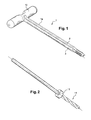
- the instrument 1 designated globally on the figures, object of the invention, is characterized in that that the lateral part la of its part auger apt preparing the location of the screw 7, has on at least one of its generators, a longitudinal recess 2, 3 open towards the outside, forming a guide intended piercing in the articulation 4 of a tunnel 5; 6 substantially hemicylindrical whose position in view of a secant piercing with the location with the screw 7 is determined by the time position of said instrument 1, so as to prepare in a first time the location of the interference screw 7 and in a second step, by piercing secant the tunnel 5, 6 for receiving a ligament or graft 8, 9, to avoid the rotation of this last training, when screwing the screw of interference 7, while allowing the immobilization in place of said ligament 8, 9 by the screw 7.
- instrument 1 has two of its generators diametrically opposed, two longitudinal recesses 2, 3 open towards outside, forming guides for drilling two substantially hemicylindrical tunnels 5, 6, their relative position being determined by a first time position of the instrument 1 when a first hole and a second position time of the same instrument 1 during a second piercing, so as to determine the location and the realization of said tunnels 5, 6 for the purpose of subsequent placement of two ligaments 8, 9, according to selected locations and their immobilization with a single screw interference 7.
- the distance from its tunnels is defined by the time position of the instrument during drilling.
- the instrument 1 is constituted by a tap, surmounted by a removable handle 10 in which opens the recesses 2, 3 in the form of two holes 2a, 3a of the diameter of the tunnels 5, 6 to realize later in the articulation 4, a such a handle 10 allowing both the rotational actuation of the tap 1 according to a predetermined depth and commitment of a tool 11 in each of the holes 2a, 3a in order to to make said tunnels 5, 6 according to angularly spaced locations, also of predetermined manner.
- the holes 2a, 3a are made in the handle 10 of the tap 1 to equal distance from the center of it, hence the interference screw 7 to put in place later.
- the diameters of the holes 2a, 3a made in the handle 10 of the tap 1 and the diameter of Hemicylindrical recesses 2, 3 which prolong them are of values adapted to the case to be treated and possibly different.
- the tap may be of diameter and of variable length, depending on the case treat.
- tunnel drilling hemi-cylindrical 5, 6 is achieved using a drilling tool 11, wick or dilator, comprising a stop end of drilling 12 and / or a graduation.
- the interference screw 7 is made in a resorbable or non-absorbable material.
- the upper part of the handle also include indications 12 indicating for example a round of tap corresponds to a 2.5mm depression.
- the longitudinal recesses 2, 3 and the holes above them 2a, 3a are drilled in the tap body for the purpose of ergonomics optimized.
- Tap 1 as described above may have variable diameters with holes for grafts of different diameters.
- a 7mm diameter tap will be equipped with two holes intended for housing grafts of diameters 4mm - 5mm.
Abstract
Description
La présente invention concerne un instrument destiné à la mise en place de vis d'interférence dans le domaine de la ligamentoplastie.The present invention relates to an instrument intended for the installation of interference screws in the field of ligamentoplasty.
Un tel instrument est indispensable à la technique de fixation applicable pour la reconstruction de ligaments intra-articulaires mais peut être utilisé également pour la fixation et la reconstruction de tendons et de ligaments extra-articulaires.Such an instrument is indispensable for fixing technique applicable for the reconstruction of intra-articular ligaments but can also be used for fixing and reconstruction of tendons and extra-articular ligaments.
Pour cela, sont connus des instruments destinés à préparer le logement de la vis d'interférence et du ligament ou greffon dans le but de fixer celui-ci dans la chirurgie de la reconstruction ligamentaire.For this purpose, instruments for to prepare the housing of the interference screw and ligament or graft in order to fix it in reconstruction surgery ligament.
Il est connu, selon la technique actuelle, de percer un trou ou tunnel du diamètre du ligament ou greffon et à fixer celui-ci par l'insertion de vis d'interférence exerçant une action entre la paroi du tunnel et ledit ligament.It is known, according to the current technique, to to drill a hole or tunnel of the diameter of the ligament or graft and fix it by inserting screws interference exerting an action between the wall tunnel and said ligament.
Les vis d'interférence étant en matériau résorbable ou non, plus ou moins fragile, il existe des tarauds adaptés au filetage de la vis pour faciliter l'insertion de celle-ci.The interference screws being made of material resorbable or not, more or less fragile, it exists taps adapted to the thread of the screw for to facilitate the insertion of this one.
La mise en place de la vis d'interférence dans le tunnel formé par un trou borgne fémoral ou dans un trou borgne tibial est donc délicate. The establishment of the interference screw in the tunnel formed by a femoral blind hole or in a tibial blind hole is delicate.
La difficulté tient essentiellement au fait que lors du vissage de la vis d'interférence, celle-ci provoque une rotation par entraínement du ligament ou tendon dans le tunnel qui est inégale, en fonction des diamètres de tous les composants en présence et du côté opéré (fémur droit ou fémur gauche).The difficulty lies mainly in the fact that when screwing the interference screw, this causes a rotation by drive of the ligament or tendon in the tunnel that is uneven, in function of the diameters of all components in presence and the operated side (right femur or femur left).
En fait, il a été constaté que de manière régulière, le greffon tourne partiellement avec la vis d'interférence ce qui induit une mauvaise position et par la même, une moins bonne isométrie.In fact, it has been found that regular, the graft turns partially with the interference screw which induces a bad position and by the same, a less good isometry.
Il faut savoir que la précision attendue dans ce type d'opération est de l'ordre du demi millimètre ou du millimètre, mais qu'en cas de rotation du greffon l'erreur de positionnement peut avoisiner 3 à 5 mm.It should be known that the expected accuracy in this type of operation is of the order of half millimeter or millimeter, but that in case of graft rotation the positioning error can to be around 3 to 5 mm.
Selon une première phase de la démarche inventive, il a été recherché un instrument qui permet de calibrer et de positionner les tunnels destinés à recevoir les ligaments ou greffons et de conserver la position de ceux-ci lors des vissages de la vis d'interférence.According to a first phase of the process inventive, he was looking for an instrument that calibrates and positions tunnels intended to receive ligaments or grafts and keep the position of these during screwing of the interference screw.
La standardisation du diamètre du logement influe directement sur l'efficacité de la fixation.Standardization of housing diameter directly affects the effectiveness of fixation.
Selon les techniques opératoires plastiques connues, l'instrument consiste en un taraud qui a pour effet de préparer le futur trajet de la vis d'interférence afin de diminuer le couple de frottement, mais en aucun cas ce taraud connu permet d'éviter les phénomènes de glissement des greffons, provoquant leur rotation, comme évoqué ci-dessus.According to plastic surgery techniques known, the instrument consists of a tap that has to prepare the future path of the screw interference in order to decrease the torque of rubbing, but by no means this known tap prevents the phenomena of slippage grafts, causing their rotation, as evoked above.
La présente invention a pour but de remédier aux différents inconvénients connus dans l'art antérieur et ci-dessus cités.The present invention aims to remedy to the various disadvantages known in the art previous and above mentioned.
A cet effet, elle concerne un instrument destiné à la mise en place de vis d'interférence dans le domaine de la ligamentoplastie intra-articulaires ou extra-articulaires, caractérisé en ce que la partie latérale de sa partie foreuse apte à la préparation de l'emplacement de la vis d'interférence, comporte sur au moins l'une de ses génératrices, un évidement longitudinal ouvert vers l'extérieur, formant un guide destiné au perçage dans l'articulation d'un tunnel sensiblement hémicylindrique dont la position en vue d'un perçage sécant avec l'emplacement avec la vis est déterminé par la position horaire dudit instrument, de manière à préparer dans un premier temps l'emplacement de la vis d'interférence et dans un deuxième temps, par perçage sécant le tunnel destiné à recevoir un ligament ou greffon, afin d'éviter la rotation de ce dernier par entraínement, lors du vissage de la vis d'interférence, tout en autorisant l'immobilisation en place dudit ligament par la vis.For this purpose, it concerns an instrument intended for the installation of interference screws in the field of intra-articular ligamentoplasty or extra-articular, characterized in what the lateral part of its part auger apt preparing the location of the screw interference, has on at least one of its generators, a longitudinal recess open towards outside, forming a guide for drilling in the articulation of a tunnel substantially hemicylindrical whose position for a secant drilling with the location with the screw is determined by the time position of said instrument, so as to prepare in a first step the location of the interference screw and in a second time, by drilling secant the tunnel intended to receive a ligament or graft, so to avoid the rotation of the latter by drive, when screwing the screw interference, while allowing the immobilisation in place of said ligament by the screw.
Il est ainsi possible de réaliser à l'identique des tunnels pour le logement d'un ou plusieurs faisceaux fémoral ou pour la partie tibiale de la reconstruction, mais aussi pour toute fixation tendino-osseuse dans tout type d'articulation.It is thus possible to perform identically tunnels for housing one or more femoral bundles or for the tibial portion of the reconstruction, but also for any fixation Tendino-bone in any type of joint.
Un tel instrument selon l'invention permet d'éviter, qu'au moment du vissage proprement dit de la vis d'interférence, celle-ci puisse entraíner dans son filetage le ou les ligament(s) ou greffon (s) .Such an instrument according to the invention allows to avoid, that at the time of the screwing proper the interference screw, this one can lead to in its thread the ligament (s) or graft (s).
La présente invention concerne également les caractéristiques qui ressortiront au cours de la description qui va suivre, et qui devront être considérées isolément ou selon toutes leurs combinaisons techniques possibles.The present invention also relates to characteristics that will emerge during the description which will follow, and which will have to be considered in isolation or in all their possible technical combinations.
Cette description donnée à titre d'exemple non
limitatif, fera mieux comprendre comment
l'invention peut être réalisée en référence aux
dessins annexés sur lesquels :
L'instrument 1 désigné globalement sur les
figures, objet de l'invention, se caractérise en ce
que la partie latérale la de sa partie foreuse apte
à la préparation de l'emplacement de la vis
d'interférence 7, comporte sur au moins l'une de
ses génératrices, un évidement longitudinal 2, 3
ouvert vers l'extérieur, formant un guide destiné
au perçage dans l'articulation 4 d'un tunnel 5; 6
sensiblement hémicylindrique dont la position en
vue d'un perçage sécant avec l'emplacement avec la
vis 7 est déterminé par la position horaire dudit
instrument 1, de manière à préparer dans un premier
temps l'emplacement de la vis d'interférence 7 et
dans un deuxième temps, par perçage sécant le
tunnel 5, 6 destiné à recevoir un ligament ou
greffon 8, 9, afin d'éviter la rotation de ce
dernier par entraínement, lors du vissage de la vis
d'interférence 7, tout en autorisant
l'immobilisation en place dudit ligament 8, 9 par
la vis 7.The
Selon les présents exemples de réalisation,
l'instrument 1 comporte sur deux de ses
génératrices diamétralement opposées, deux
évidements longitudinaux 2, 3 ouverts vers
l'extérieur, formant des guides destinés au perçage
de deux tunnels 5, 6 sensiblement hémicylindriques,
leur position relative étant déterminée par une
première position horaire de l'instrument 1 lors
d'un premier perçage et par une deuxième position
horaire du même instrument 1 lors d'un second
perçage, de manière à déterminer l'emplacement et
la réalisation desdits tunnels 5, 6 en vue de la
mise en place ultérieure de deux ligaments 8, 9,
selon des emplacements choisis et de leur
immobilisation à l'aide d'une seule vis
d'interférence 7.According to the present embodiments,
Ceci a pour effet de diminuer la quantité de matériaux résorbables ou non implantée, comparée à une technique à deux faisceaux fixés par deux vis d'interférence au niveau fémoral selon l'art antérieur.This has the effect of reducing the amount of resorbable or non-implanted materials compared to a technique with two beams fixed by two screws interference at the femoral level according to art prior.
En fait, l'espacement entre les tunnels 5, 6
destiné à la mise en place de deux ligaments
fémoraux 8, 9 est maítrisé par l'intermédiaire de
l'instrument 1 à deux évidements longitudinaux 2,
3.In fact, the spacing between
C'est la rotation de l'instrument 1 qui défini
le bon positionnement des tunnels 5, 6 à réaliser. It is the rotation of the
L'éloignement de ses tunnels est défini par la position horaire de l'instrument lors des perçages.The distance from its tunnels is defined by the time position of the instrument during drilling.
Ceux-ci sont à égale distance du centre des vis et la distance par rapport à la cortical est donnée par l'utilisation d'un viseur fémoral décalé à 7, 8 ou 9 mm, connu dans l'art antérieur.These are equidistant from the center of the screws and the distance to the cortical is given by using a femoral viewfinder shifted to 7, 8 or 9 mm, known in the prior art.
Selon une autre caractéristique de l'invention,
l'instrument 1 est constitué par un taraud,
surmonté par une poignée amovible 10 dans laquelle
débouche les évidements 2, 3 sous forme de deux
trous 2a, 3a du diamètre des tunnels 5, 6 à
réaliser ultérieurement dans l'articulation 4, une
telle poignée 10 permettant à la fois
l'actionnement en rotation du taraud 1 selon une
profondeur prédéterminée et l'engagement d'un outil
de forage 11 dans chacun des trous 2a, 3a afin de
réaliser lesdits tunnels 5, 6 selon des
emplacements espacés angulairement, également de
manière prédéterminée.According to another characteristic of the invention,
the
Ainsi, et comme déjà évoqué les trous 2a, 3a
sont réalisés dans la poignée 10 du taraud 1 à
égale distance du centre de celui-ci, d'où de la
vis d'interférence 7 à mettre en place
ultérieurement.Thus, and as already mentioned the
Les diamètres des trous 2a, 3a réalisés dans la
poignée 10 du taraud 1 et le diamètre des
évidements hémicylindrique 2, 3 qui les prolongent
sont de valeurs adaptées au cas à traiter et
éventuellement différentes. The diameters of the
Bien entendu, le taraud pourra être de diamètre et de longueur variables, en fonction du cas à traiter.Of course, the tap may be of diameter and of variable length, depending on the case treat.
Par ailleurs, le perçage du tunnel
hémicylindrique 5, 6 est réalisé à l'aide d'un
outil de forage 11, mèche ou dilatateur, comportant
une butée de fin de forage 12 et/ou une graduation.In addition, tunnel drilling
hemi-cylindrical 5, 6 is achieved using a
Egalement, la vis d'interférence 7 est réalisée
en un matériau résorbable ou non résorbable.Also, the
La partie supérieure de la poignée pourra
également comporter des indications 12 indiquant
par exemple qu'un tour de taraud correspond à un
enfoncement de 2,5mm.The upper part of the handle
also include
En résumé, le taraud 1 doit permettre, par l'intermédiaire de la poignée 10 percée de deux trous 2a, 3a, se prolongeant sur toute la longueur du taraud 1 par les évidements 2, 3 :
- de visser le
taraud 1 dans un trou borgne préalablement réalisé dans l'articulation 4, en creusant le filet de la vis d'interférence 7, - une fois le
taraud 1 introduit dans le condyle, il est possible d'engager un outil de forage pouvant être en butée ou graduée, afin de préparer lestunnels ligaments
- to screw the
tap 1 into a blind hole previously made in thehinge 4, by digging the thread of theinterference screw 7, - once the
tap 1 introduced into the condyle, it is possible to engage a drilling tool that can be abutment or graduated, to prepare thetunnels ligaments
Les évidements longitudinaux 2, 3 ainsi que les
trous les surmontant 2a, 3a sont percés dans le
corps du taraud dans le but d'une ergonomie
optimisée.The
Il est possible d'avoir une poignée 11 amovible
afin de faciliter la mise en place des outils de
forage 11.It is possible to have a
Il est possible d'avoir des évidements 2, 3 non
rétentifs, semi-rétentifs ou complètement
rétentifs.It is possible to have
Il est également possible d'avoir un filet de taraud taraudant ou auto-taraudant.It is also possible to have a net of tap or self-tapping tap.
Il est possible également d'utiliser un
instrument qui ne soit pas un taraud, en fait, un
instrument de perçage tel qu'un foret ou des
dilatateurs, tout comme il est possible de réaliser
un instrument monobloc incluant un impacteur
dilatateur monobloc pour réaliser les trois
perçages simultanément à savoir : les deux tunnels
5, 6 ; et le trou borgne constituant l'emplacement
de la vis d'interférence 7.It is also possible to use a
instrument that is not a tap, in fact, a
piercing instrument such as a drill or
dilators, just as it is possible to achieve
a monobloc instrument including an impactor
monobloc dilator to achieve the three
boring simultaneously namely: the two
Le taraud 1 tel que décrit ci-dessus peut avoir
des diamètres variables avec des trous destinés à
des greffons de diamètres différents.
Par exemple, un taraud de diamètre 7mm sera muni de deux trous destinés au logements des greffons de diamètres 4mm - 5mm. For example, a 7mm diameter tap will be equipped with two holes intended for housing grafts of diameters 4mm - 5mm.
La facilité avec laquelle la vis 7 peut être
introduite dans le trou borgne qui lui est destiné
peut même amener le chirurgien a changer la taille
de la vis 7.The ease with which
Ainsi, il lui est possible de surdimensionner la vis d'un ou deux millimètres.Thus, it is possible for him to oversize the screw of one or two millimeters.
Par exemple une vis de 8mm sur un taraudage de 7mm ou une vis de 9mm sur un taraudage à 8mm, ceci pour améliorer la stabilité primaire en fonction de la densité osseuse rencontrée.For example an 8mm screw on a thread of 7mm or a 9mm screw on an 8mm thread, this to improve primary stability as a function of the bone density encountered.
Claims (9)
Applications Claiming Priority (2)
| Application Number | Priority Date | Filing Date | Title |
|---|---|---|---|
| FR0311643A FR2860418B1 (en) | 2003-10-02 | 2003-10-02 | INSTRUMENT FOR THE INSTALLATION OF INTERFERENCE SCREWS IN THE FIELD OF LIGAMENTOPLASTY |
| FR0311643 | 2003-10-02 |
Publications (2)
| Publication Number | Publication Date |
|---|---|
| EP1520534A1 true EP1520534A1 (en) | 2005-04-06 |
| EP1520534B1 EP1520534B1 (en) | 2006-09-06 |
Family
ID=34307426
Family Applications (1)
| Application Number | Title | Priority Date | Filing Date |
|---|---|---|---|
| EP04021515A Not-in-force EP1520534B1 (en) | 2003-10-02 | 2004-09-10 | Instrument for preparation of a bone for an interference screw in ligament surgery |
Country Status (5)
| Country | Link |
|---|---|
| EP (1) | EP1520534B1 (en) |
| AT (1) | ATE338515T1 (en) |
| DE (1) | DE602004002255T2 (en) |
| ES (1) | ES2273137T3 (en) |
| FR (1) | FR2860418B1 (en) |
Cited By (3)
| Publication number | Priority date | Publication date | Assignee | Title |
|---|---|---|---|---|
| FR2938745A1 (en) * | 2008-09-12 | 2010-05-28 | Tettra Marketing Llp | TAP FOR PLACING A CAGE OF A FIXING DEVICE FOR LIGAMENTOPLASTY |
| CN103006312A (en) * | 2010-09-03 | 2013-04-03 | 张强 | Minimally-invasive bone fracture screw imbedding and opening apparatus |
| CN103315804A (en) * | 2013-06-09 | 2013-09-25 | 无锡市华牧机械有限公司 | Screw tap specially used in orthopaedics department |
Families Citing this family (1)
| Publication number | Priority date | Publication date | Assignee | Title |
|---|---|---|---|---|
| GB2443795B (en) * | 2006-10-06 | 2011-04-13 | Dalmatic As | Leads for use in orthopaedic surgery |
Citations (4)
| Publication number | Priority date | Publication date | Assignee | Title |
|---|---|---|---|---|
| US5234430A (en) * | 1991-12-18 | 1993-08-10 | Huebner Randall J | Orthopedic fixation screw and method |
| FR2735008A1 (en) * | 1995-06-07 | 1996-12-13 | Jbs Sa | Surgical instrument for inter vertebral arthrodesis |
| US5643269A (en) * | 1990-08-24 | 1997-07-01 | Haerle; Anton | Externally threaded bodies for use as taps or screws |
| US20030018337A1 (en) * | 2001-07-17 | 2003-01-23 | Davis Reginald J. | Bone drill and tap combination |
-
2003
- 2003-10-02 FR FR0311643A patent/FR2860418B1/en not_active Expired - Fee Related
-
2004
- 2004-09-10 EP EP04021515A patent/EP1520534B1/en not_active Not-in-force
- 2004-09-10 DE DE602004002255T patent/DE602004002255T2/en active Active
- 2004-09-10 AT AT04021515T patent/ATE338515T1/en not_active IP Right Cessation
- 2004-09-10 ES ES04021515T patent/ES2273137T3/en active Active
Patent Citations (4)
| Publication number | Priority date | Publication date | Assignee | Title |
|---|---|---|---|---|
| US5643269A (en) * | 1990-08-24 | 1997-07-01 | Haerle; Anton | Externally threaded bodies for use as taps or screws |
| US5234430A (en) * | 1991-12-18 | 1993-08-10 | Huebner Randall J | Orthopedic fixation screw and method |
| FR2735008A1 (en) * | 1995-06-07 | 1996-12-13 | Jbs Sa | Surgical instrument for inter vertebral arthrodesis |
| US20030018337A1 (en) * | 2001-07-17 | 2003-01-23 | Davis Reginald J. | Bone drill and tap combination |
Cited By (3)
| Publication number | Priority date | Publication date | Assignee | Title |
|---|---|---|---|---|
| FR2938745A1 (en) * | 2008-09-12 | 2010-05-28 | Tettra Marketing Llp | TAP FOR PLACING A CAGE OF A FIXING DEVICE FOR LIGAMENTOPLASTY |
| CN103006312A (en) * | 2010-09-03 | 2013-04-03 | 张强 | Minimally-invasive bone fracture screw imbedding and opening apparatus |
| CN103315804A (en) * | 2013-06-09 | 2013-09-25 | 无锡市华牧机械有限公司 | Screw tap specially used in orthopaedics department |
Also Published As
| Publication number | Publication date |
|---|---|
| FR2860418B1 (en) | 2005-12-16 |
| ES2273137T3 (en) | 2007-05-01 |
| DE602004002255D1 (en) | 2006-10-19 |
| ATE338515T1 (en) | 2006-09-15 |
| EP1520534B1 (en) | 2006-09-06 |
| FR2860418A1 (en) | 2005-04-08 |
| DE602004002255T2 (en) | 2007-04-05 |
Similar Documents
| Publication | Publication Date | Title |
|---|---|---|
| EP1074230B1 (en) | Malleolar implant for a partial or total ankle prosthesis and ancillary equipment for fitting such an implant | |
| FR2944692A1 (en) | MATERIAL OF VERTEBRAL OSTEOSYNTHESIS | |
| EP0856293B1 (en) | Bone screw for connecting small bone fragments | |
| EP0983755B1 (en) | Implant for flat foot | |
| FR2649604A1 (en) | SURGICAL ANCILLARY INSTRUMENT FOR TRACKING THE ENTRY AND DIRECTION OF THE TUNNEL OF FEMALE INSERTION OF A NEO-LIGAMENT UNDER CONDITIONS OF TOTAL ISOMETRY | |
| EP0599752A1 (en) | Osteosynthesis device for trochanter or intertrochanter fracture | |
| EP0814730A1 (en) | Surgical anchoring piece for ligaments | |
| FR2556583A1 (en) | Osteosynthesis plates for bone derotation, in particular for femoral derotation | |
| FR2572648A1 (en) | HIP SCREW SCREW DEVICE FOR FEMUR FRACTURE REDUCTION | |
| CH627935A5 (en) | Set of parts for the implementation of a process osteosynthesis. | |
| FR2750031A1 (en) | Suture thread bone anchor for torn shoulder tendon or ligament | |
| FR2459650A1 (en) | INTRAMEDULAR COMPRESSION DEVICE FOR BONE FRACTURE | |
| WO2003024369A2 (en) | Device for delivering a biomaterial | |
| WO2010094846A1 (en) | Device to assist with the placement of screws in bone tissue and instrument applying said device, in particular for performing osteosynthesis of bone fragments | |
| FR2560764A1 (en) | Forceps for the reduction of fractures | |
| EP1520534B1 (en) | Instrument for preparation of a bone for an interference screw in ligament surgery | |
| FR2879915A1 (en) | Interference screw for fixing ligament, has inner channel with grooves and flutes which are oriented longitudinally and distributed uniformly along surface of inner channel which extends through another channel emerging at level of point | |
| FR2804598A1 (en) | DEVICE FOR FIXING AN IMPLANT OR TRANSPLANT FORMING PROSTHETIC LIGAMENT ON BONE | |
| FR2683716A1 (en) | REINFORCED GRAFT FOR LIGAMENTOPLASTY OF THE KNEE. | |
| FR2787699A1 (en) | Initial hole making instrument for bone staple comprises rigid holder, template apertures and drill guide with metal bushes | |
| FR2924596A1 (en) | Fixation device for ligamentoplasty, has hollow cage having outer wall terminated at level of upper end by threading or by smooth part having external diameter lesser than or equal to inner diameter of threading | |
| CA2138413A1 (en) | Ancillary instrument for coracoclavicular ligament plasty | |
| FR3021206A1 (en) | OSTEOSYNTHESIS SCREW FOR SOLIDARIZING BONE FRAGMENTS | |
| FR2917283A1 (en) | INSTRUMENT FOR THE INSTALLATION OF A PROSTHESIS OF SHOULDER. | |
| FR2948275A1 (en) | FEMUR PREPARATION SURGICAL INSTRUMENTATION FOR THE PLACEMENT OF A DUAL BEAM TRANSPLANT FOR RECONSTRUCTING AN ANCIENT CROSS LIGAMENT |
Legal Events
| Date | Code | Title | Description |
|---|---|---|---|
| PUAI | Public reference made under article 153(3) epc to a published international application that has entered the european phase |
Free format text: ORIGINAL CODE: 0009012 |
|
| AK | Designated contracting states |
Kind code of ref document: A1 Designated state(s): AT BE BG CH CY CZ DE DK EE ES FI FR GB GR HU IE IT LI LU MC NL PL PT RO SE SI SK TR |
|
| AX | Request for extension of the european patent |
Extension state: AL HR LT LV MK |
|
| 17P | Request for examination filed |
Effective date: 20050608 |
|
| AKX | Designation fees paid |
Designated state(s): AT BE BG CH CY CZ DE DK EE ES FI FR GB GR HU IE IT LI LU MC NL PL PT RO SE SI SK TR |
|
| GRAP | Despatch of communication of intention to grant a patent |
Free format text: ORIGINAL CODE: EPIDOSNIGR1 |
|
| GRAS | Grant fee paid |
Free format text: ORIGINAL CODE: EPIDOSNIGR3 |
|
| GRAA | (expected) grant |
Free format text: ORIGINAL CODE: 0009210 |
|
| AK | Designated contracting states |
Kind code of ref document: B1 Designated state(s): AT BE BG CH CY CZ DE DK EE ES FI FR GB GR HU IE IT LI LU MC NL PL PT RO SE SI SK TR |
|
| PG25 | Lapsed in a contracting state [announced via postgrant information from national office to epo] |
Ref country code: FI Free format text: LAPSE BECAUSE OF FAILURE TO SUBMIT A TRANSLATION OF THE DESCRIPTION OR TO PAY THE FEE WITHIN THE PRESCRIBED TIME-LIMIT Effective date: 20060906 Ref country code: PL Free format text: LAPSE BECAUSE OF FAILURE TO SUBMIT A TRANSLATION OF THE DESCRIPTION OR TO PAY THE FEE WITHIN THE PRESCRIBED TIME-LIMIT Effective date: 20060906 Ref country code: IE Free format text: LAPSE BECAUSE OF FAILURE TO SUBMIT A TRANSLATION OF THE DESCRIPTION OR TO PAY THE FEE WITHIN THE PRESCRIBED TIME-LIMIT Effective date: 20060906 Ref country code: SK Free format text: LAPSE BECAUSE OF FAILURE TO SUBMIT A TRANSLATION OF THE DESCRIPTION OR TO PAY THE FEE WITHIN THE PRESCRIBED TIME-LIMIT Effective date: 20060906 Ref country code: SI Free format text: LAPSE BECAUSE OF FAILURE TO SUBMIT A TRANSLATION OF THE DESCRIPTION OR TO PAY THE FEE WITHIN THE PRESCRIBED TIME-LIMIT Effective date: 20060906 Ref country code: CZ Free format text: LAPSE BECAUSE OF FAILURE TO SUBMIT A TRANSLATION OF THE DESCRIPTION OR TO PAY THE FEE WITHIN THE PRESCRIBED TIME-LIMIT Effective date: 20060906 Ref country code: RO Free format text: LAPSE BECAUSE OF FAILURE TO SUBMIT A TRANSLATION OF THE DESCRIPTION OR TO PAY THE FEE WITHIN THE PRESCRIBED TIME-LIMIT Effective date: 20060906 Ref country code: AT Free format text: LAPSE BECAUSE OF FAILURE TO SUBMIT A TRANSLATION OF THE DESCRIPTION OR TO PAY THE FEE WITHIN THE PRESCRIBED TIME-LIMIT Effective date: 20060906 |
|
| REG | Reference to a national code |
Ref country code: GB Ref legal event code: FG4D Free format text: NOT ENGLISH |
|
| REG | Reference to a national code |
Ref country code: CH Ref legal event code: EP |
|
| PG25 | Lapsed in a contracting state [announced via postgrant information from national office to epo] |
Ref country code: MC Free format text: LAPSE BECAUSE OF NON-PAYMENT OF DUE FEES Effective date: 20060930 |
|
| REG | Reference to a national code |
Ref country code: IE Ref legal event code: FG4D Free format text: LANGUAGE OF EP DOCUMENT: FRENCH |
|
| REF | Corresponds to: |
Ref document number: 602004002255 Country of ref document: DE Date of ref document: 20061019 Kind code of ref document: P |
|
| PG25 | Lapsed in a contracting state [announced via postgrant information from national office to epo] |
Ref country code: SE Free format text: LAPSE BECAUSE OF FAILURE TO SUBMIT A TRANSLATION OF THE DESCRIPTION OR TO PAY THE FEE WITHIN THE PRESCRIBED TIME-LIMIT Effective date: 20061206 Ref country code: BG Free format text: LAPSE BECAUSE OF FAILURE TO SUBMIT A TRANSLATION OF THE DESCRIPTION OR TO PAY THE FEE WITHIN THE PRESCRIBED TIME-LIMIT Effective date: 20061206 Ref country code: DK Free format text: LAPSE BECAUSE OF FAILURE TO SUBMIT A TRANSLATION OF THE DESCRIPTION OR TO PAY THE FEE WITHIN THE PRESCRIBED TIME-LIMIT Effective date: 20061206 |
|
| GBT | Gb: translation of ep patent filed (gb section 77(6)(a)/1977) |
Effective date: 20061120 |
|
| REG | Reference to a national code |
Ref country code: CH Ref legal event code: NV Representative=s name: WILLIAM BLANC & CIE CONSEILS EN PROPRIETE INDUSTRI |
|
| PG25 | Lapsed in a contracting state [announced via postgrant information from national office to epo] |
Ref country code: PT Free format text: LAPSE BECAUSE OF FAILURE TO SUBMIT A TRANSLATION OF THE DESCRIPTION OR TO PAY THE FEE WITHIN THE PRESCRIBED TIME-LIMIT Effective date: 20070219 |
|
| REG | Reference to a national code |
Ref country code: IE Ref legal event code: FD4D |
|
| REG | Reference to a national code |
Ref country code: ES Ref legal event code: FG2A Ref document number: 2273137 Country of ref document: ES Kind code of ref document: T3 |
|
| PLBE | No opposition filed within time limit |
Free format text: ORIGINAL CODE: 0009261 |
|
| STAA | Information on the status of an ep patent application or granted ep patent |
Free format text: STATUS: NO OPPOSITION FILED WITHIN TIME LIMIT |
|
| 26N | No opposition filed |
Effective date: 20070607 |
|
| PG25 | Lapsed in a contracting state [announced via postgrant information from national office to epo] |
Ref country code: GR Free format text: LAPSE BECAUSE OF FAILURE TO SUBMIT A TRANSLATION OF THE DESCRIPTION OR TO PAY THE FEE WITHIN THE PRESCRIBED TIME-LIMIT Effective date: 20061207 |
|
| PG25 | Lapsed in a contracting state [announced via postgrant information from national office to epo] |
Ref country code: EE Free format text: LAPSE BECAUSE OF FAILURE TO SUBMIT A TRANSLATION OF THE DESCRIPTION OR TO PAY THE FEE WITHIN THE PRESCRIBED TIME-LIMIT Effective date: 20060906 |
|
| PG25 | Lapsed in a contracting state [announced via postgrant information from national office to epo] |
Ref country code: HU Free format text: LAPSE BECAUSE OF FAILURE TO SUBMIT A TRANSLATION OF THE DESCRIPTION OR TO PAY THE FEE WITHIN THE PRESCRIBED TIME-LIMIT Effective date: 20070307 Ref country code: LU Free format text: LAPSE BECAUSE OF NON-PAYMENT OF DUE FEES Effective date: 20060910 Ref country code: TR Free format text: LAPSE BECAUSE OF FAILURE TO SUBMIT A TRANSLATION OF THE DESCRIPTION OR TO PAY THE FEE WITHIN THE PRESCRIBED TIME-LIMIT Effective date: 20060906 |
|
| REG | Reference to a national code |
Ref country code: CH Ref legal event code: PFA Owner name: DESARNAUD, MICHEL Free format text: CENTERPULSE FRANCE SA#127, RUE RENE JACOT, TECHNOLAND#25460 ETUPES CEDEX (FR) $ DESARNAUD, MICHEL#7, RUE BEGUE-DAVID#31400 TOULOUSE (FR) -TRANSFER TO- DESARNAUD, MICHEL#7, RUE BEGUE-DAVID#31400 TOULOUSE (FR) $ ZIMMER FRANCE SAS#127, AVENUE RENE JACOT BP 34#25461 ETUPES CEDEX (FR) |
|
| PG25 | Lapsed in a contracting state [announced via postgrant information from national office to epo] |
Ref country code: CY Free format text: LAPSE BECAUSE OF FAILURE TO SUBMIT A TRANSLATION OF THE DESCRIPTION OR TO PAY THE FEE WITHIN THE PRESCRIBED TIME-LIMIT Effective date: 20060906 |
|
| NLT1 | Nl: modifications of names registered in virtue of documents presented to the patent office pursuant to art. 16 a, paragraph 1 |
Owner name: MICHEL DESARNAUD Owner name: ZIMMER FRANCE |
|
| REG | Reference to a national code |
Ref country code: FR Ref legal event code: CJ Ref country code: FR Ref legal event code: CD |
|
| REG | Reference to a national code |
Ref country code: CH Ref legal event code: PFA Owner name: DESARNAUD, MICHEL Free format text: DESARNAUD, MICHEL#7, RUE BEGUE-DAVID#31400 TOULOUSE (FR) $ ZIMMER FRANCE SAS#127, AVENUE RENE JACOT BP 34#25461 ETUPES CEDEX (FR) -TRANSFER TO- DESARNAUD, MICHEL#7, RUE BEGUE-DAVID#31400 TOULOUSE (FR) $ ZIMMER FRANCE SAS#127, AVENUE RENE JACOT BP 34#25461 ETUPES CEDEX (FR) |
|
| REG | Reference to a national code |
Ref country code: CH Ref legal event code: PCAR Free format text: NOVAGRAAF SWITZERLAND SA;CHEMIN DE L'ECHO 3;1213 ONEX (CH) |
|
| REG | Reference to a national code |
Ref country code: FR Ref legal event code: PLFP Year of fee payment: 12 |
|
| REG | Reference to a national code |
Ref country code: FR Ref legal event code: PLFP Year of fee payment: 13 |
|
| REG | Reference to a national code |
Ref country code: FR Ref legal event code: PLFP Year of fee payment: 14 |
|
| PGFP | Annual fee paid to national office [announced via postgrant information from national office to epo] |
Ref country code: BE Payment date: 20170724 Year of fee payment: 14 Ref country code: NL Payment date: 20170919 Year of fee payment: 14 |
|
| PGFP | Annual fee paid to national office [announced via postgrant information from national office to epo] |
Ref country code: ES Payment date: 20171002 Year of fee payment: 14 |
|
| REG | Reference to a national code |
Ref country code: FR Ref legal event code: PLFP Year of fee payment: 15 |
|
| REG | Reference to a national code |
Ref country code: NL Ref legal event code: MM Effective date: 20181001 |
|
| REG | Reference to a national code |
Ref country code: BE Ref legal event code: MM Effective date: 20180930 |
|
| PG25 | Lapsed in a contracting state [announced via postgrant information from national office to epo] |
Ref country code: NL Free format text: LAPSE BECAUSE OF NON-PAYMENT OF DUE FEES Effective date: 20181001 |
|
| PG25 | Lapsed in a contracting state [announced via postgrant information from national office to epo] |
Ref country code: BE Free format text: LAPSE BECAUSE OF NON-PAYMENT OF DUE FEES Effective date: 20180930 |
|
| REG | Reference to a national code |
Ref country code: ES Ref legal event code: FD2A Effective date: 20191030 |
|
| PGFP | Annual fee paid to national office [announced via postgrant information from national office to epo] |
Ref country code: IT Payment date: 20190712 Year of fee payment: 16 Ref country code: FR Payment date: 20190809 Year of fee payment: 16 |
|
| PG25 | Lapsed in a contracting state [announced via postgrant information from national office to epo] |
Ref country code: ES Free format text: LAPSE BECAUSE OF NON-PAYMENT OF DUE FEES Effective date: 20180911 |
|
| PG25 | Lapsed in a contracting state [announced via postgrant information from national office to epo] |
Ref country code: FR Free format text: LAPSE BECAUSE OF NON-PAYMENT OF DUE FEES Effective date: 20200930 |
|
| PGFP | Annual fee paid to national office [announced via postgrant information from national office to epo] |
Ref country code: GB Payment date: 20210810 Year of fee payment: 18 Ref country code: DE Payment date: 20210813 Year of fee payment: 18 Ref country code: CH Payment date: 20210816 Year of fee payment: 18 |
|
| PG25 | Lapsed in a contracting state [announced via postgrant information from national office to epo] |
Ref country code: IT Free format text: LAPSE BECAUSE OF NON-PAYMENT OF DUE FEES Effective date: 20200910 |
|
| REG | Reference to a national code |
Ref country code: DE Ref legal event code: R119 Ref document number: 602004002255 Country of ref document: DE |
|
| REG | Reference to a national code |
Ref country code: CH Ref legal event code: PL |
|
| GBPC | Gb: european patent ceased through non-payment of renewal fee |
Effective date: 20220910 |
|
| PG25 | Lapsed in a contracting state [announced via postgrant information from national office to epo] |
Ref country code: LI Free format text: LAPSE BECAUSE OF NON-PAYMENT OF DUE FEES Effective date: 20220930 Ref country code: DE Free format text: LAPSE BECAUSE OF NON-PAYMENT OF DUE FEES Effective date: 20230401 Ref country code: CH Free format text: LAPSE BECAUSE OF NON-PAYMENT OF DUE FEES Effective date: 20220930 |
|
| PG25 | Lapsed in a contracting state [announced via postgrant information from national office to epo] |
Ref country code: GB Free format text: LAPSE BECAUSE OF NON-PAYMENT OF DUE FEES Effective date: 20220910 |