EP1520519B1 - Heart wall tension reduction apparatus - Google Patents
Heart wall tension reduction apparatus Download PDFInfo
- Publication number
- EP1520519B1 EP1520519B1 EP04078441A EP04078441A EP1520519B1 EP 1520519 B1 EP1520519 B1 EP 1520519B1 EP 04078441 A EP04078441 A EP 04078441A EP 04078441 A EP04078441 A EP 04078441A EP 1520519 B1 EP1520519 B1 EP 1520519B1
- Authority
- EP
- European Patent Office
- Prior art keywords
- heart
- anchor
- tension member
- pad
- wall
- Prior art date
- Legal status (The legal status is an assumption and is not a legal conclusion. Google has not performed a legal analysis and makes no representation as to the accuracy of the status listed.)
- Expired - Lifetime
Links
- 210000002216 heart Anatomy 0.000 title claims abstract description 148
- 230000009467 reduction Effects 0.000 title description 10
- 210000005240 left ventricle Anatomy 0.000 claims description 60
- 210000001519 tissue Anatomy 0.000 claims description 19
- 239000000463 material Substances 0.000 claims description 15
- 238000000576 coating method Methods 0.000 claims description 12
- 239000004810 polytetrafluoroethylene Substances 0.000 claims description 8
- 229920001343 polytetrafluoroethylene Polymers 0.000 claims description 8
- 239000011248 coating agent Substances 0.000 claims description 7
- 239000000835 fiber Substances 0.000 claims description 6
- 230000007246 mechanism Effects 0.000 claims description 6
- 239000003550 marker Substances 0.000 claims description 5
- 229910001000 nickel titanium Inorganic materials 0.000 claims description 5
- 210000003540 papillary muscle Anatomy 0.000 claims description 5
- 102000008186 Collagen Human genes 0.000 claims description 4
- 108010035532 Collagen Proteins 0.000 claims description 4
- 229910001069 Ti alloy Inorganic materials 0.000 claims description 4
- 210000001367 artery Anatomy 0.000 claims description 4
- 229910001220 stainless steel Inorganic materials 0.000 claims description 4
- 239000010935 stainless steel Substances 0.000 claims description 4
- OKTJSMMVPCPJKN-UHFFFAOYSA-N Carbon Chemical compound [C] OKTJSMMVPCPJKN-UHFFFAOYSA-N 0.000 claims description 3
- 229920001436 collagen Polymers 0.000 claims description 3
- 229940079593 drug Drugs 0.000 claims description 3
- 239000003814 drug Substances 0.000 claims description 3
- 230000001939 inductive effect Effects 0.000 claims description 3
- 229920001296 polysiloxane Polymers 0.000 claims description 3
- JOYRKODLDBILNP-UHFFFAOYSA-N Ethyl urethane Chemical compound CCOC(N)=O JOYRKODLDBILNP-UHFFFAOYSA-N 0.000 claims description 2
- 239000000853 adhesive Substances 0.000 claims description 2
- 230000001070 adhesive effect Effects 0.000 claims description 2
- 229910001285 shape-memory alloy Inorganic materials 0.000 claims description 2
- 229910052799 carbon Inorganic materials 0.000 claims 2
- 238000000034 method Methods 0.000 abstract description 14
- 210000005242 cardiac chamber Anatomy 0.000 abstract description 9
- 238000011282 treatment Methods 0.000 abstract description 5
- 230000006835 compression Effects 0.000 description 17
- 238000007906 compression Methods 0.000 description 17
- 210000005241 right ventricle Anatomy 0.000 description 15
- 230000002861 ventricular Effects 0.000 description 10
- 230000000747 cardiac effect Effects 0.000 description 8
- 206010019280 Heart failures Diseases 0.000 description 7
- 230000008859 change Effects 0.000 description 7
- 231100000241 scar Toxicity 0.000 description 7
- 210000003205 muscle Anatomy 0.000 description 6
- 230000008602 contraction Effects 0.000 description 5
- 230000001965 increasing effect Effects 0.000 description 5
- 229910052751 metal Inorganic materials 0.000 description 5
- 239000002184 metal Substances 0.000 description 5
- 230000036961 partial effect Effects 0.000 description 5
- 230000008569 process Effects 0.000 description 5
- 239000000560 biocompatible material Substances 0.000 description 4
- 230000000740 bleeding effect Effects 0.000 description 4
- 230000003205 diastolic effect Effects 0.000 description 4
- 201000010099 disease Diseases 0.000 description 4
- 208000037265 diseases, disorders, signs and symptoms Diseases 0.000 description 4
- 210000005246 left atrium Anatomy 0.000 description 4
- 239000011148 porous material Substances 0.000 description 4
- 230000002829 reductive effect Effects 0.000 description 4
- 238000009966 trimming Methods 0.000 description 4
- RTAQQCXQSZGOHL-UHFFFAOYSA-N Titanium Chemical compound [Ti] RTAQQCXQSZGOHL-UHFFFAOYSA-N 0.000 description 3
- 230000003466 anti-cipated effect Effects 0.000 description 3
- 230000017531 blood circulation Effects 0.000 description 3
- 238000005520 cutting process Methods 0.000 description 3
- 230000006378 damage Effects 0.000 description 3
- 238000009826 distribution Methods 0.000 description 3
- 239000002934 diuretic Substances 0.000 description 3
- 229940030606 diuretics Drugs 0.000 description 3
- 230000006870 function Effects 0.000 description 3
- 210000004165 myocardium Anatomy 0.000 description 3
- 230000036316 preload Effects 0.000 description 3
- 238000005086 pumping Methods 0.000 description 3
- 230000007480 spreading Effects 0.000 description 3
- 238000003892 spreading Methods 0.000 description 3
- 239000010936 titanium Substances 0.000 description 3
- 229910052719 titanium Inorganic materials 0.000 description 3
- 238000002054 transplantation Methods 0.000 description 3
- 0 C1[*+]2C1CCCC2 Chemical compound C1[*+]2C1CCCC2 0.000 description 2
- 206010016803 Fluid overload Diseases 0.000 description 2
- 206010020880 Hypertrophy Diseases 0.000 description 2
- 229920000106 Liquid crystal polymer Polymers 0.000 description 2
- 239000004977 Liquid-crystal polymers (LCPs) Substances 0.000 description 2
- 238000013459 approach Methods 0.000 description 2
- 239000008280 blood Substances 0.000 description 2
- 210000004369 blood Anatomy 0.000 description 2
- 230000001684 chronic effect Effects 0.000 description 2
- 210000004351 coronary vessel Anatomy 0.000 description 2
- 238000010438 heat treatment Methods 0.000 description 2
- 239000007943 implant Substances 0.000 description 2
- 238000002513 implantation Methods 0.000 description 2
- 238000012544 monitoring process Methods 0.000 description 2
- 210000000107 myocyte Anatomy 0.000 description 2
- HLXZNVUGXRDIFK-UHFFFAOYSA-N nickel titanium Chemical compound [Ti].[Ti].[Ti].[Ti].[Ti].[Ti].[Ti].[Ti].[Ti].[Ti].[Ti].[Ni].[Ni].[Ni].[Ni].[Ni].[Ni].[Ni].[Ni].[Ni].[Ni].[Ni].[Ni].[Ni].[Ni] HLXZNVUGXRDIFK-UHFFFAOYSA-N 0.000 description 2
- 230000000144 pharmacologic effect Effects 0.000 description 2
- BASFCYQUMIYNBI-UHFFFAOYSA-N platinum Chemical compound [Pt] BASFCYQUMIYNBI-UHFFFAOYSA-N 0.000 description 2
- 230000002441 reversible effect Effects 0.000 description 2
- 210000002235 sarcomere Anatomy 0.000 description 2
- 239000007787 solid Substances 0.000 description 2
- 238000001356 surgical procedure Methods 0.000 description 2
- OERNJTNJEZOPIA-UHFFFAOYSA-N zirconium nitrate Chemical compound [Zr+4].[O-][N+]([O-])=O.[O-][N+]([O-])=O.[O-][N+]([O-])=O.[O-][N+]([O-])=O OERNJTNJEZOPIA-UHFFFAOYSA-N 0.000 description 2
- 239000005541 ACE inhibitor Substances 0.000 description 1
- 102000009027 Albumins Human genes 0.000 description 1
- 108010088751 Albumins Proteins 0.000 description 1
- 206010002329 Aneurysm Diseases 0.000 description 1
- YULMNMJFAZWLLN-UHFFFAOYSA-N C=C1CCCCC1 Chemical compound C=C1CCCCC1 YULMNMJFAZWLLN-UHFFFAOYSA-N 0.000 description 1
- ZMVNHOBRHOOPNP-UHFFFAOYSA-N CC(CNC)C([IH]O)=C Chemical compound CC(CNC)C([IH]O)=C ZMVNHOBRHOOPNP-UHFFFAOYSA-N 0.000 description 1
- 229920000049 Carbon (fiber) Polymers 0.000 description 1
- 206010007559 Cardiac failure congestive Diseases 0.000 description 1
- 206010053567 Coagulopathies Diseases 0.000 description 1
- 229920001651 Cyanoacrylate Polymers 0.000 description 1
- 229920004934 Dacron® Polymers 0.000 description 1
- LTMHDMANZUZIPE-AMTYYWEZSA-N Digoxin Natural products O([C@H]1[C@H](C)O[C@H](O[C@@H]2C[C@@H]3[C@@](C)([C@@H]4[C@H]([C@]5(O)[C@](C)([C@H](O)C4)[C@H](C4=CC(=O)OC4)CC5)CC3)CC2)C[C@@H]1O)[C@H]1O[C@H](C)[C@@H](O[C@H]2O[C@@H](C)[C@H](O)[C@@H](O)C2)[C@@H](O)C1 LTMHDMANZUZIPE-AMTYYWEZSA-N 0.000 description 1
- 201000010046 Dilated cardiomyopathy Diseases 0.000 description 1
- 206010018910 Haemolysis Diseases 0.000 description 1
- HTTJABKRGRZYRN-UHFFFAOYSA-N Heparin Chemical compound OC1C(NC(=O)C)C(O)OC(COS(O)(=O)=O)C1OC1C(OS(O)(=O)=O)C(O)C(OC2C(C(OS(O)(=O)=O)C(OC3C(C(O)C(O)C(O3)C(O)=O)OS(O)(=O)=O)C(CO)O2)NS(O)(=O)=O)C(C(O)=O)O1 HTTJABKRGRZYRN-UHFFFAOYSA-N 0.000 description 1
- 206010048858 Ischaemic cardiomyopathy Diseases 0.000 description 1
- 229920000271 Kevlar® Polymers 0.000 description 1
- MWCLLHOVUTZFKS-UHFFFAOYSA-N Methyl cyanoacrylate Chemical compound COC(=O)C(=C)C#N MWCLLHOVUTZFKS-UHFFFAOYSA-N 0.000 description 1
- 206010028311 Muscle hypertrophy Diseases 0.000 description 1
- 208000029549 Muscle injury Diseases 0.000 description 1
- 206010068767 Viral cardiomyopathy Diseases 0.000 description 1
- 208000027418 Wounds and injury Diseases 0.000 description 1
- HZEWFHLRYVTOIW-UHFFFAOYSA-N [Ti].[Ni] Chemical compound [Ti].[Ni] HZEWFHLRYVTOIW-UHFFFAOYSA-N 0.000 description 1
- 230000005856 abnormality Effects 0.000 description 1
- 238000005299 abrasion Methods 0.000 description 1
- 229960001138 acetylsalicylic acid Drugs 0.000 description 1
- 230000036982 action potential Effects 0.000 description 1
- 230000006978 adaptation Effects 0.000 description 1
- 230000003044 adaptive effect Effects 0.000 description 1
- 230000002411 adverse Effects 0.000 description 1
- 229910045601 alloy Inorganic materials 0.000 description 1
- 239000000956 alloy Substances 0.000 description 1
- 238000004873 anchoring Methods 0.000 description 1
- 229940044094 angiotensin-converting-enzyme inhibitor Drugs 0.000 description 1
- 238000000137 annealing Methods 0.000 description 1
- 239000002260 anti-inflammatory agent Substances 0.000 description 1
- 230000002965 anti-thrombogenic effect Effects 0.000 description 1
- 230000036528 appetite Effects 0.000 description 1
- 235000019789 appetite Nutrition 0.000 description 1
- 238000005452 bending Methods 0.000 description 1
- 230000009286 beneficial effect Effects 0.000 description 1
- 239000011230 binding agent Substances 0.000 description 1
- 230000036760 body temperature Effects 0.000 description 1
- 238000009954 braiding Methods 0.000 description 1
- -1 but not limited to Substances 0.000 description 1
- 229910052791 calcium Inorganic materials 0.000 description 1
- 239000011575 calcium Substances 0.000 description 1
- 239000004917 carbon fiber Substances 0.000 description 1
- 239000003575 carbonaceous material Substances 0.000 description 1
- 229940097217 cardiac glycoside Drugs 0.000 description 1
- 239000002368 cardiac glycoside Substances 0.000 description 1
- 230000022900 cardiac muscle contraction Effects 0.000 description 1
- 230000035602 clotting Effects 0.000 description 1
- 229940072645 coumadin Drugs 0.000 description 1
- 230000007423 decrease Effects 0.000 description 1
- 229910003460 diamond Inorganic materials 0.000 description 1
- 239000010432 diamond Substances 0.000 description 1
- 230000035487 diastolic blood pressure Effects 0.000 description 1
- 229960005156 digoxin Drugs 0.000 description 1
- LTMHDMANZUZIPE-PUGKRICDSA-N digoxin Chemical compound C1[C@H](O)[C@H](O)[C@@H](C)O[C@H]1O[C@@H]1[C@@H](C)O[C@@H](O[C@@H]2[C@H](O[C@@H](O[C@@H]3C[C@@H]4[C@]([C@@H]5[C@H]([C@]6(CC[C@@H]([C@@]6(C)[C@H](O)C5)C=5COC(=O)C=5)O)CC4)(C)CC3)C[C@@H]2O)C)C[C@@H]1O LTMHDMANZUZIPE-PUGKRICDSA-N 0.000 description 1
- LTMHDMANZUZIPE-UHFFFAOYSA-N digoxine Natural products C1C(O)C(O)C(C)OC1OC1C(C)OC(OC2C(OC(OC3CC4C(C5C(C6(CCC(C6(C)C(O)C5)C=5COC(=O)C=5)O)CC4)(C)CC3)CC2O)C)CC1O LTMHDMANZUZIPE-UHFFFAOYSA-N 0.000 description 1
- 201000011304 dilated cardiomyopathy 1A Diseases 0.000 description 1
- 230000010339 dilation Effects 0.000 description 1
- 238000002651 drug therapy Methods 0.000 description 1
- 230000000694 effects Effects 0.000 description 1
- 239000002305 electric material Substances 0.000 description 1
- 229910000701 elgiloys (Co-Cr-Ni Alloy) Inorganic materials 0.000 description 1
- 238000005265 energy consumption Methods 0.000 description 1
- 210000003722 extracellular fluid Anatomy 0.000 description 1
- 238000002594 fluoroscopy Methods 0.000 description 1
- 239000011521 glass Substances 0.000 description 1
- 239000003292 glue Substances 0.000 description 1
- PCHJSUWPFVWCPO-UHFFFAOYSA-N gold Chemical compound [Au] PCHJSUWPFVWCPO-UHFFFAOYSA-N 0.000 description 1
- 229910052737 gold Inorganic materials 0.000 description 1
- 239000010931 gold Substances 0.000 description 1
- 229910002804 graphite Inorganic materials 0.000 description 1
- 239000010439 graphite Substances 0.000 description 1
- 210000002837 heart atrium Anatomy 0.000 description 1
- 208000019622 heart disease Diseases 0.000 description 1
- 230000004217 heart function Effects 0.000 description 1
- 229910001385 heavy metal Inorganic materials 0.000 description 1
- 230000008588 hemolysis Effects 0.000 description 1
- 229960002897 heparin Drugs 0.000 description 1
- 229920000669 heparin Polymers 0.000 description 1
- 208000022368 idiopathic cardiomyopathy Diseases 0.000 description 1
- 238000002650 immunosuppressive therapy Methods 0.000 description 1
- 238000001727 in vivo Methods 0.000 description 1
- 208000014674 injury Diseases 0.000 description 1
- 230000002452 interceptive effect Effects 0.000 description 1
- 230000007794 irritation Effects 0.000 description 1
- 208000028867 ischemia Diseases 0.000 description 1
- 239000004761 kevlar Substances 0.000 description 1
- 230000007774 longterm Effects 0.000 description 1
- QSHDDOUJBYECFT-UHFFFAOYSA-N mercury Chemical compound [Hg] QSHDDOUJBYECFT-UHFFFAOYSA-N 0.000 description 1
- 229910052753 mercury Inorganic materials 0.000 description 1
- VNWKTOKETHGBQD-UHFFFAOYSA-N methane Chemical compound C VNWKTOKETHGBQD-UHFFFAOYSA-N 0.000 description 1
- 238000012806 monitoring device Methods 0.000 description 1
- 230000012042 muscle hypertrophy Effects 0.000 description 1
- 230000003387 muscular Effects 0.000 description 1
- 150000002823 nitrates Chemical class 0.000 description 1
- 210000000056 organ Anatomy 0.000 description 1
- TWNQGVIAIRXVLR-UHFFFAOYSA-N oxo(oxoalumanyloxy)alumane Chemical compound O=[Al]O[Al]=O TWNQGVIAIRXVLR-UHFFFAOYSA-N 0.000 description 1
- RVTZCBVAJQQJTK-UHFFFAOYSA-N oxygen(2-);zirconium(4+) Chemical class [O-2].[O-2].[Zr+4] RVTZCBVAJQQJTK-UHFFFAOYSA-N 0.000 description 1
- 238000011458 pharmacological treatment Methods 0.000 description 1
- 230000008288 physiological mechanism Effects 0.000 description 1
- 229910052697 platinum Inorganic materials 0.000 description 1
- 239000005020 polyethylene terephthalate Substances 0.000 description 1
- 229920000642 polymer Polymers 0.000 description 1
- 239000002296 pyrolytic carbon Substances 0.000 description 1
- 238000007634 remodeling Methods 0.000 description 1
- 230000000630 rising effect Effects 0.000 description 1
- 238000004904 shortening Methods 0.000 description 1
- 210000002027 skeletal muscle Anatomy 0.000 description 1
- 238000001228 spectrum Methods 0.000 description 1
- 229910001256 stainless steel alloy Inorganic materials 0.000 description 1
- 229930002534 steroid glycoside Natural products 0.000 description 1
- 150000008143 steroidal glycosides Chemical class 0.000 description 1
- 230000004936 stimulating effect Effects 0.000 description 1
- 239000000126 substance Substances 0.000 description 1
- 208000011580 syndromic disease Diseases 0.000 description 1
- 230000008719 thickening Effects 0.000 description 1
- QORWJWZARLRLPR-UHFFFAOYSA-H tricalcium bis(phosphate) Chemical compound [Ca+2].[Ca+2].[Ca+2].[O-]P([O-])([O-])=O.[O-]P([O-])([O-])=O QORWJWZARLRLPR-UHFFFAOYSA-H 0.000 description 1
- 150000003673 urethanes Chemical class 0.000 description 1
- 229940124549 vasodilator Drugs 0.000 description 1
- 239000003071 vasodilator agent Substances 0.000 description 1
- 238000007794 visualization technique Methods 0.000 description 1
- PJVWKTKQMONHTI-UHFFFAOYSA-N warfarin Chemical compound OC=1C2=CC=CC=C2OC(=O)C=1C(CC(=O)C)C1=CC=CC=C1 PJVWKTKQMONHTI-UHFFFAOYSA-N 0.000 description 1
- 229910001928 zirconium oxide Inorganic materials 0.000 description 1
Images


Classifications
-
- A—HUMAN NECESSITIES
- A61—MEDICAL OR VETERINARY SCIENCE; HYGIENE
- A61B—DIAGNOSIS; SURGERY; IDENTIFICATION
- A61B17/00—Surgical instruments, devices or methods, e.g. tourniquets
- A61B17/04—Surgical instruments, devices or methods, e.g. tourniquets for suturing wounds; Holders or packages for needles or suture materials
- A61B17/06—Needles ; Sutures; Needle-suture combinations; Holders or packages for needles or suture materials
- A61B17/06166—Sutures
-
- A—HUMAN NECESSITIES
- A61—MEDICAL OR VETERINARY SCIENCE; HYGIENE
- A61B—DIAGNOSIS; SURGERY; IDENTIFICATION
- A61B17/00—Surgical instruments, devices or methods, e.g. tourniquets
- A61B17/00234—Surgical instruments, devices or methods, e.g. tourniquets for minimally invasive surgery
-
- A—HUMAN NECESSITIES
- A61—MEDICAL OR VETERINARY SCIENCE; HYGIENE
- A61F—FILTERS IMPLANTABLE INTO BLOOD VESSELS; PROSTHESES; DEVICES PROVIDING PATENCY TO, OR PREVENTING COLLAPSING OF, TUBULAR STRUCTURES OF THE BODY, e.g. STENTS; ORTHOPAEDIC, NURSING OR CONTRACEPTIVE DEVICES; FOMENTATION; TREATMENT OR PROTECTION OF EYES OR EARS; BANDAGES, DRESSINGS OR ABSORBENT PADS; FIRST-AID KITS
- A61F2/00—Filters implantable into blood vessels; Prostheses, i.e. artificial substitutes or replacements for parts of the body; Appliances for connecting them with the body; Devices providing patency to, or preventing collapsing of, tubular structures of the body, e.g. stents
- A61F2/02—Prostheses implantable into the body
- A61F2/24—Heart valves ; Vascular valves, e.g. venous valves; Heart implants, e.g. passive devices for improving the function of the native valve or the heart muscle; Transmyocardial revascularisation [TMR] devices; Valves implantable in the body
- A61F2/2478—Passive devices for improving the function of the heart muscle, i.e. devices for reshaping the external surface of the heart, e.g. bags, strips or bands
- A61F2/2487—Devices within the heart chamber, e.g. splints
-
- A—HUMAN NECESSITIES
- A61—MEDICAL OR VETERINARY SCIENCE; HYGIENE
- A61B—DIAGNOSIS; SURGERY; IDENTIFICATION
- A61B17/00—Surgical instruments, devices or methods, e.g. tourniquets
- A61B17/00491—Surgical glue applicators
-
- A—HUMAN NECESSITIES
- A61—MEDICAL OR VETERINARY SCIENCE; HYGIENE
- A61B—DIAGNOSIS; SURGERY; IDENTIFICATION
- A61B17/00—Surgical instruments, devices or methods, e.g. tourniquets
- A61B17/04—Surgical instruments, devices or methods, e.g. tourniquets for suturing wounds; Holders or packages for needles or suture materials
- A61B17/0401—Suture anchors, buttons or pledgets, i.e. means for attaching sutures to bone, cartilage or soft tissue; Instruments for applying or removing suture anchors
-
- A—HUMAN NECESSITIES
- A61—MEDICAL OR VETERINARY SCIENCE; HYGIENE
- A61B—DIAGNOSIS; SURGERY; IDENTIFICATION
- A61B17/00—Surgical instruments, devices or methods, e.g. tourniquets
- A61B17/04—Surgical instruments, devices or methods, e.g. tourniquets for suturing wounds; Holders or packages for needles or suture materials
- A61B17/0487—Suture clamps, clips or locks, e.g. for replacing suture knots; Instruments for applying or removing suture clamps, clips or locks
-
- A—HUMAN NECESSITIES
- A61—MEDICAL OR VETERINARY SCIENCE; HYGIENE
- A61B—DIAGNOSIS; SURGERY; IDENTIFICATION
- A61B17/00—Surgical instruments, devices or methods, e.g. tourniquets
- A61B17/12—Surgical instruments, devices or methods, e.g. tourniquets for ligaturing or otherwise compressing tubular parts of the body, e.g. blood vessels, umbilical cord
- A61B17/122—Clamps or clips, e.g. for the umbilical cord
- A61B17/1227—Spring clips
-
- A—HUMAN NECESSITIES
- A61—MEDICAL OR VETERINARY SCIENCE; HYGIENE
- A61B—DIAGNOSIS; SURGERY; IDENTIFICATION
- A61B17/00—Surgical instruments, devices or methods, e.g. tourniquets
- A61B17/00234—Surgical instruments, devices or methods, e.g. tourniquets for minimally invasive surgery
- A61B2017/00238—Type of minimally invasive operation
- A61B2017/00243—Type of minimally invasive operation cardiac
-
- A—HUMAN NECESSITIES
- A61—MEDICAL OR VETERINARY SCIENCE; HYGIENE
- A61B—DIAGNOSIS; SURGERY; IDENTIFICATION
- A61B17/00—Surgical instruments, devices or methods, e.g. tourniquets
- A61B17/04—Surgical instruments, devices or methods, e.g. tourniquets for suturing wounds; Holders or packages for needles or suture materials
- A61B17/0401—Suture anchors, buttons or pledgets, i.e. means for attaching sutures to bone, cartilage or soft tissue; Instruments for applying or removing suture anchors
- A61B2017/0404—Buttons
-
- A—HUMAN NECESSITIES
- A61—MEDICAL OR VETERINARY SCIENCE; HYGIENE
- A61B—DIAGNOSIS; SURGERY; IDENTIFICATION
- A61B17/00—Surgical instruments, devices or methods, e.g. tourniquets
- A61B17/04—Surgical instruments, devices or methods, e.g. tourniquets for suturing wounds; Holders or packages for needles or suture materials
- A61B17/0401—Suture anchors, buttons or pledgets, i.e. means for attaching sutures to bone, cartilage or soft tissue; Instruments for applying or removing suture anchors
- A61B2017/0417—T-fasteners
-
- A—HUMAN NECESSITIES
- A61—MEDICAL OR VETERINARY SCIENCE; HYGIENE
- A61B—DIAGNOSIS; SURGERY; IDENTIFICATION
- A61B17/00—Surgical instruments, devices or methods, e.g. tourniquets
- A61B17/04—Surgical instruments, devices or methods, e.g. tourniquets for suturing wounds; Holders or packages for needles or suture materials
- A61B17/0401—Suture anchors, buttons or pledgets, i.e. means for attaching sutures to bone, cartilage or soft tissue; Instruments for applying or removing suture anchors
- A61B2017/0427—Suture anchors, buttons or pledgets, i.e. means for attaching sutures to bone, cartilage or soft tissue; Instruments for applying or removing suture anchors having anchoring barbs or pins extending outwardly from the anchor body
- A61B2017/0435—Suture anchors, buttons or pledgets, i.e. means for attaching sutures to bone, cartilage or soft tissue; Instruments for applying or removing suture anchors having anchoring barbs or pins extending outwardly from the anchor body the barbs being separate elements mechanically linked to the anchor, e.g. by pivots
-
- A—HUMAN NECESSITIES
- A61—MEDICAL OR VETERINARY SCIENCE; HYGIENE
- A61B—DIAGNOSIS; SURGERY; IDENTIFICATION
- A61B17/00—Surgical instruments, devices or methods, e.g. tourniquets
- A61B17/04—Surgical instruments, devices or methods, e.g. tourniquets for suturing wounds; Holders or packages for needles or suture materials
- A61B17/0401—Suture anchors, buttons or pledgets, i.e. means for attaching sutures to bone, cartilage or soft tissue; Instruments for applying or removing suture anchors
- A61B2017/0445—Suture anchors, buttons or pledgets, i.e. means for attaching sutures to bone, cartilage or soft tissue; Instruments for applying or removing suture anchors cannulated, e.g. with a longitudinal through-hole for passage of an instrument
-
- A—HUMAN NECESSITIES
- A61—MEDICAL OR VETERINARY SCIENCE; HYGIENE
- A61B—DIAGNOSIS; SURGERY; IDENTIFICATION
- A61B17/00—Surgical instruments, devices or methods, e.g. tourniquets
- A61B17/04—Surgical instruments, devices or methods, e.g. tourniquets for suturing wounds; Holders or packages for needles or suture materials
- A61B17/0401—Suture anchors, buttons or pledgets, i.e. means for attaching sutures to bone, cartilage or soft tissue; Instruments for applying or removing suture anchors
- A61B2017/0446—Means for attaching and blocking the suture in the suture anchor
- A61B2017/0454—Means for attaching and blocking the suture in the suture anchor the anchor being crimped or clamped on the suture
-
- A—HUMAN NECESSITIES
- A61—MEDICAL OR VETERINARY SCIENCE; HYGIENE
- A61B—DIAGNOSIS; SURGERY; IDENTIFICATION
- A61B17/00—Surgical instruments, devices or methods, e.g. tourniquets
- A61B17/04—Surgical instruments, devices or methods, e.g. tourniquets for suturing wounds; Holders or packages for needles or suture materials
- A61B17/0401—Suture anchors, buttons or pledgets, i.e. means for attaching sutures to bone, cartilage or soft tissue; Instruments for applying or removing suture anchors
- A61B2017/0446—Means for attaching and blocking the suture in the suture anchor
- A61B2017/0458—Longitudinal through hole, e.g. suture blocked by a distal suture knot
-
- A—HUMAN NECESSITIES
- A61—MEDICAL OR VETERINARY SCIENCE; HYGIENE
- A61B—DIAGNOSIS; SURGERY; IDENTIFICATION
- A61B17/00—Surgical instruments, devices or methods, e.g. tourniquets
- A61B17/04—Surgical instruments, devices or methods, e.g. tourniquets for suturing wounds; Holders or packages for needles or suture materials
- A61B17/0401—Suture anchors, buttons or pledgets, i.e. means for attaching sutures to bone, cartilage or soft tissue; Instruments for applying or removing suture anchors
- A61B2017/0446—Means for attaching and blocking the suture in the suture anchor
- A61B2017/0461—Means for attaching and blocking the suture in the suture anchor with features cooperating with special features on the suture, e.g. protrusions on the suture
-
- A—HUMAN NECESSITIES
- A61—MEDICAL OR VETERINARY SCIENCE; HYGIENE
- A61B—DIAGNOSIS; SURGERY; IDENTIFICATION
- A61B17/00—Surgical instruments, devices or methods, e.g. tourniquets
- A61B17/04—Surgical instruments, devices or methods, e.g. tourniquets for suturing wounds; Holders or packages for needles or suture materials
- A61B17/0401—Suture anchors, buttons or pledgets, i.e. means for attaching sutures to bone, cartilage or soft tissue; Instruments for applying or removing suture anchors
- A61B2017/0464—Suture anchors, buttons or pledgets, i.e. means for attaching sutures to bone, cartilage or soft tissue; Instruments for applying or removing suture anchors for soft tissue
-
- A—HUMAN NECESSITIES
- A61—MEDICAL OR VETERINARY SCIENCE; HYGIENE
- A61B—DIAGNOSIS; SURGERY; IDENTIFICATION
- A61B17/00—Surgical instruments, devices or methods, e.g. tourniquets
- A61B17/04—Surgical instruments, devices or methods, e.g. tourniquets for suturing wounds; Holders or packages for needles or suture materials
- A61B17/0469—Suturing instruments for use in minimally invasive surgery, e.g. endoscopic surgery
- A61B2017/048—Suturing instruments for use in minimally invasive surgery, e.g. endoscopic surgery for reducing heart wall tension, e.g. sutures with a pad on each extremity
-
- A—HUMAN NECESSITIES
- A61—MEDICAL OR VETERINARY SCIENCE; HYGIENE
- A61B—DIAGNOSIS; SURGERY; IDENTIFICATION
- A61B17/00—Surgical instruments, devices or methods, e.g. tourniquets
- A61B17/04—Surgical instruments, devices or methods, e.g. tourniquets for suturing wounds; Holders or packages for needles or suture materials
- A61B2017/0496—Surgical instruments, devices or methods, e.g. tourniquets for suturing wounds; Holders or packages for needles or suture materials for tensioning sutures
-
- A—HUMAN NECESSITIES
- A61—MEDICAL OR VETERINARY SCIENCE; HYGIENE
- A61B—DIAGNOSIS; SURGERY; IDENTIFICATION
- A61B90/00—Instruments, implements or accessories specially adapted for surgery or diagnosis and not covered by any of the groups A61B1/00 - A61B50/00, e.g. for luxation treatment or for protecting wound edges
- A61B90/39—Markers, e.g. radio-opaque or breast lesions markers
-
- A—HUMAN NECESSITIES
- A61—MEDICAL OR VETERINARY SCIENCE; HYGIENE
- A61F—FILTERS IMPLANTABLE INTO BLOOD VESSELS; PROSTHESES; DEVICES PROVIDING PATENCY TO, OR PREVENTING COLLAPSING OF, TUBULAR STRUCTURES OF THE BODY, e.g. STENTS; ORTHOPAEDIC, NURSING OR CONTRACEPTIVE DEVICES; FOMENTATION; TREATMENT OR PROTECTION OF EYES OR EARS; BANDAGES, DRESSINGS OR ABSORBENT PADS; FIRST-AID KITS
- A61F2/00—Filters implantable into blood vessels; Prostheses, i.e. artificial substitutes or replacements for parts of the body; Appliances for connecting them with the body; Devices providing patency to, or preventing collapsing of, tubular structures of the body, e.g. stents
- A61F2/02—Prostheses implantable into the body
- A61F2/24—Heart valves ; Vascular valves, e.g. venous valves; Heart implants, e.g. passive devices for improving the function of the native valve or the heart muscle; Transmyocardial revascularisation [TMR] devices; Valves implantable in the body
- A61F2/2478—Passive devices for improving the function of the heart muscle, i.e. devices for reshaping the external surface of the heart, e.g. bags, strips or bands
- A61F2/2481—Devices outside the heart wall, e.g. bags, strips or bands
Definitions
- the present invention pertains to the field of apparatus for treatment of a failing heart.
- the apparatus of the present invention is directed toward reducing the wall stress in the failing heart.
- Heart failure is a common course for the progression of many forms of heart disease.
- Heart failure may be considered to be the condition in which an abnormality of cardiac function is responsible for the inability of the heart to pump blood at a rate commensurate with the requirements of the metabolizing tissues, or can do so only at an abnormally elevated filling pressure.
- the process of ventricular dilatation is generally the result of chronic volume overload or specific damage to the myocardium.
- cardiac output requirements for example, that of an athlete
- damage to the myocardium or chronic volume overload there are increased requirements put on the contracting myocardium to such a level that this compensated state is never achieved and the heart continues to dilate.
- the basic problem with a large dilated left ventricle is that there is a significant increase in wall tension and/or stress both during diastolic filling and during systolic contraction.
- the adaptation of muscle hypertrophy (thickening) and ventricular dilatation maintain a fairly constant wall tension for systolic contraction.
- the ongoing dilatation is greater than the hypertrophy and the result is a rising wall tension requirement for systolic contraction. This is felt to be an ongoing insult to the muscle myocyte resulting in further muscle damage.
- the increase in wall stress is also true for diastolic filling.
- Prior art treatments for heart failure fall into three generally categories. The first being pharmacological, for example, diuretics. The second being assist systems, for example, pumps. Finally, surgical treatments have been experimented with, which are described in more detail below.
- diuretics have been used to reduce the workload of the heart by reducing blood volume and preload.
- preload is defined in several ways including left ventricular end diastolic pressure (LVEDP), or left ventricular end diastolic volume (LVEDV).
- LEDP left ventricular end diastolic pressure
- LVEDV left ventricular end diastolic volume
- the preferred definition is the length of stretch of the sarcomere at end diastole.
- Diuretics reduce extra cellular fluid which builds in congestive heart failure patients increasing preload conditions.
- Nitrates, arteriolar vasodilators, angiotensin converting enzyme inhibitors have been used to treat heart failure through the reduction of cardiac workload through the reduction of afterload.
- Afterload may be defined as the tension or stress required in the wall of the ventricle during ejection.
- Inotropes like digoxin are cardiac glycosides and function to increase cardiac output by increasing the force and speed of cardiac muscle contraction.
- Assist devices include mechanical pumps. Mechanical pumps reduce the load on the heart by performing all or part of the pumping function normally done by the heart. Currently, mechanical pumps are used to sustain the patient while a donor heart for transplantation becomes available for the patient.
- Heart transplantation has serious limitations including restricted availability of organs and adverse effects of immunosuppressive therapies required following heart transplantation.
- Cardiomyoplasty includes wrapping the heart with skeletal muscle and electrically stimulating the muscle to contract synchronously with the heart in order to help the pumping function of the heart.
- the Batista partial left ventriculectomy includes surgically remodeling the left ventricle by removing a segment of the muscular wall. This procedure reduces the diameter of the dilated heart, which in turn reduces the loading of the heart. However, this extremely invasive procedure reduces muscle mass of the heart.
- the present invention pertains to a non-pharmacological, passive apparatus for the treatment of a failing heart.
- the device is configured to reduce the tension in the heart wall. It is believed to reverse, stop or slow the disease process of a failing heart as it reduces the energy consumption of the failing heart, decreases isovolumetric contraction, increases isotonic contraction (sarcomere shortening), which in turn increases stroke volume.
- the device reduces wall tension during diastole and systole.
- Splints can be grouped as either “full cycle splints” which engage the heart to produce a chamber shape change throughout the cardiac cycle, or “restrictive splints” which do not engage the heart wall at end systole to produce a chamber shape change.
- the apparatus includes a tension member for drawing at least two walls of the heart chamber toward each other to reduce the radius or area of the heart chamber in at least one cross sectional plane.
- the tension member has anchoring members disposed at opposite ends for engagement with the heart or chamber wall.
- a heart wall tension reduction apparatus which includes a first tension member having two oppositely disposed ends and first and second elongate anchor members.
- a second tension member can be provided.
- One of the elongate anchors may be substituted for by two smaller anchors.
- an elongate compression member can be provided.
- First and second elongate lever members preferably extend from opposite ends of the compression member.
- a tension member extends between the first and second lever members.
- the compression member of the above embodiment can be disposed exterior to, or internally of the heart.
- the tension member extends through the chamber or chambers to bias the lever members toward the heart.
- a rigid elongate frame member in accordance with the present invention, can extend through one or more chambers of the heart.
- One or more cantilever members can be disposed at opposite ends of the frame member.
- Each cantilever member includes at least one atraumatic pad disposed thereon. The atraumatic pads disposed at opposite ends of the frame member can be biased toward each other to compress the heart chamber.
- One method of placing a heart wall tension apparatus or splint on a human heart includes the step of extending a hollow needle through at least one chamber of the heart such that each end of the needle is external to the chamber.
- a flexible leader is connected to a first end of a tension member.
- a second end of the tension member is connected to an atraumatic pad.
- the leader is advanced through the needle from one end of the needle to the other.
- the leader is further advanced until the second end of the tension member is proximate the heart and the first end of the tension member is external to the heart.
- a second atraumatic pad is connected to the first end of the tension member such that the first and second atraumatic pads engage the heart.
- Yet another method of placing a heart wall tension apparatus on a heart includes the step of extending a needle having a flexible tension member releasably connected thereto through at least one chamber of the heart such that opposite ends of the tension member are external to the chamber and exposed on opposite sides of the chamber.
- the needle is removed from the tension member.
- first and second atraumatic pads are connected to the tension member at opposite ends of the tension member.
- Figure 1 shows a transverse cross-section of a left ventricle 10 and a right ventricle 12 of a human heart 14. Extending through the left ventricle is a splint 16 including a tension member 18 and oppositely disposed anchors 20. Splint 16 as shown in Figure 1 has been positioned to draw opposite walls of left ventricle 10 toward each other to reduce the "radius" of the left ventricular cross-section or the cross-sectional area thereof to reduce left ventricular wall stresses.
- splint 16 and the alternative devices disclosed herein are described in relation to the left ventricle of a human heart, these devices could also be used to reduce the radius or cross-sectional area of the other chambers of a human heart in transverse or vertical directions, or at an angle between the transverse and vertical.
- splints Those apparatus of the present invention which reduce heart wall stress by changing chamber wall geometry can be referred to as "splints".
- “Full cycle splints” engage the heart to produce a chamber shape change throughout the cardiac cycle.
- “Restrictive splints” do not engage the heart wall at end systole to produce a chamber shape change.
- Figure 2 discloses a device not forming part of the present invention, wherein a balloon 200 is deployed adjacent the left ventricle.
- the size and degree of inflation of the balloon can be varied to reduce the radius or cross-sectional area of left ventricle 10 of heart 14.
- Figure 3 shows yet another device not forming part of the present invention deployed with respect to left ventricle 10 of human heart 14.
- a compression frame structure 300 is engaged with heart 14 at atraumatic anchor pads 310.
- a compression member 312 having an atraumatic surface 314 presses against a wall of left ventricle 10 to reduce the radius or cross-sectional area thereof.
- Figure 4 is a transverse cross-sectional view of human heart 14 showing yet another device not forming part of the present invention.
- a clamp 400 having atraumatic anchor pads 410 biased toward each other is shown disposed on a wall of left ventricle 10.
- the radius or cross-sectional area of left ventricle 10 is reduced by clamping off the portion of the wall between pads 410.
- Pads 410 can be biased toward each other and/or can be held together by a locking device.
- FIGS 1 and 2 can be made from materials which can remain implanted in the human body indefinitely. Such biocompatible materials are well-known to those skilled in the art of clinical medical devices.
- Figure 5 shows an alternate embodiment of the splint of Figure 1 referred to in Figure 5 by the numeral 116.
- the embodiment 116 shown in Figure 5 includes three tension members 118 as opposed to a single tension member 18 as shown in Figure 1.
- Figure 6 shows yet another embodiment of the splint 216 having four tension members 218. It is anticipated that in some patients, the disease process of the failing heart may be so advanced that three, four or more tension members may be desirable to reduce the heart wall stresses more substantially than possible with a single tension member as shown in Figure 1 .
- Figure 7 is a partial vertical cross-section of human heart 14 showing left ventricle 10.
- another splint embodiment 316 is shown having a tension member 318 extending through left ventricle 10.
- tension member 318 On opposite ends of tension member 318 are disposed elongate anchors or pads 320.
- Figure 8 is an end view of tension member 318 showing elongate anchor 320.
- FIG 9 shows another embodiment of a splint 416 disposed in a partial vertical cross-section of human heart 14.
- Splint 416 includes two elongate anchors or pads 420 similar to those shown in Figures 7 and 8 . In Figure 9 , however, two tension members 418 extend through left ventricle 10 to interconnect anchors 420 on opposite sides of heart 14.
- Figure 10 is a vertical cross section of heart 14 showing left ventricle 10.
- two splints 16 are disposed through left ventricle 10 and vertically spaced from each other to resemble the configuration of Figure 9 .
- FIG 11 is a vertical cross sectional view of the left ventricle of heart 14.
- Two alternate embodiment splints 516 are shown extending through left ventricle 10.
- Each splint 516 includes two tension members 518 interconnecting two anchors or pads 520.
- Figure 12 is yet another vertical cross sectional view of left ventricle 10 of heart 14.
- An alternate embodiment 616 of the splint is shown extending through left ventricle 10.
- Splint 616 includes an elongate anchor pad 620 and two shorter anchors or pads 621.
- Splint 616 includes two tension members 618. Each tension member 618 extends between anchors 620 and respective anchors 621.
- Figure 13 is a vertical cross sectional view of left ventricle 10 of heart 14.
- a splint 50 is shown disposed on heart 14.
- Splint 50 includes a compression member 52 shown extending through left ventricle 10. Opposite ends of compression member 52 are disposed exterior to left ventricle 10.
- Lever members 54 extend from each end of compression member 52 upwardly along the exterior surface of ventricle 10.
- a tension member 56 extends between lever members 54 to bias lever members 54 toward heart 14 to compress chamber 10.
- Compression member 52 should be substantially rigid, but lever members 54 and to some degree compression member 52 should be flexible enough to allow tension member 56 to bias lever members 54 toward heart 14.
- lever members 54 could be hinged to compression member 52 such that lever members 54 could pivot about the hinge when biased toward heart 14 by tension member 56.
- Figure 14 shows an alternate embodiment 156 of the splint shown in Figure 13 .
- lever members 154 are longer than members 54 as compression member 152 of splint 150 has been disposed to the exterior of left ventricle 10.
- Figure 15 is a vertical cross sectional view of left ventricle 10 of heart 14.
- An alternate embodiment 250 of the splint is shown on heart 14.
- a preferably relatively rigid frame member 256 extends through ventricle 10.
- cantilever member 254 Disposed on opposite ends of frame 256 are cantilever member 254.
- cantilever members 254 Disposed on cantilever members 254 are atraumatic pads 258.
- Cantilever members 254 can be positioned along frame member 256 such that atraumatic pads 258 press against heart 14 to compress chamber 10.
- Figure 16 is an end view of frame member 256 showing cantilever members 254 and pads 258.
- the tension members can be formed from flexible or relatively more rigid material.
- the compression members and frame member should be formed from generally rigid material which may flex under load, but generally hold its shape.
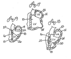
- Figure 17 is a partial vertical cross-section of human heart 14 showing left ventricle 10 and left atrium 22.
- heart 14 includes a region of scar tissue 24 associated with an aneurysm or ischemia.
- the scar tissue 24 increases the radius or cross-sectional area of left ventricle 10 in the region affected by the scar tissue. Such an increase in the radius or cross-sectional area of the left ventricle will result in greater wall stresses on the walls of the left ventricle.
- Figure 18 is a vertical cross-sectional view of the heart 14 as shown in Figure 17 , wherein a splint 16 has been placed to draw the scar tissue 24 toward an opposite wall of left ventricle 10.
- a splint 16 has been placed to draw the scar tissue 24 toward an opposite wall of left ventricle 10.
- the radius or cross-sectional area of the left ventricle affected by the scar tissue 24 is reduced.
- the reduction of this radius or cross-sectional area results in reduction in the wall stress in the left ventricular wall and thus improves heart pumping efficiency.
- Figure 19 is a vertical cross-sectional view of left ventricle 10 and left atrium 22 of heart 14 in which a splint 16 has been placed.
- splint 16 includes an alternative anchor 26.
- the anchor 20 is preferably an elongate member having a length as shown in Figure 9 substantially greater than its width (not shown).
- Anchor bar 26 might be used to reduce the radius or cross-sectional area of the left ventricle in an instance where there is generalized enlargement of left ventricle 10 such as in idiopathic dilated cardiomyopathy. In such an instance, bar anchor 26 can distribute forces more widely than anchor 20.
- FIGS 20 and 21 are side views of a hinged anchor 28 which could be substituted for anchors 20 in undeployed and deployed positions respectively.
- Anchor 28 as shown in Figure 20 includes two legs 29 similar to bar anchor 26.
- Hinged anchor 28 could include additional legs and the length of those legs could be varied to distribute the force over the surface of the heart wall.
- the webbing would be disposed on the surface of the legs which would be in contact with the heart wall.
- FIG 22 is a cross-sectional view of a capture ball anchor 30.
- Capture ball anchor 30 can be used in place of anchor 20.
- Capture ball anchor 30 includes a disk portion 32 to distribute the force of the anchor on the heart wall, and a recess 34 for receiving a ball 36 affixed to an end of tension member 18.
- Disk 32 and recess 34 include a side groove which allows tension member 18 to be passed from an outside edge of disk 32 into recess 34.
- Ball 36 can then be advanced into recess 34 by drawing tension member 18 through an opening 38 in recess 34 opposite disk 32.
- Figure 23 is a perspective view of a cross bar anchor 40.
- the cross bar anchor 40 can be used in place of anchors 20.
- the anchor 40 preferably includes a disk or pad portion 42 having a cross bar 44 extending over an opening 46 in pad 42.
- Tension member 18 can be extended through opening 46 and tied to cross bar 42 as shown.
- FIG 24 is a cross sectional view of an alternate embodiment of anchor pad 340 in accordance with the present invention.
- Anchor pad 340 preferably includes a disc shaped pad portion 342.
- Disc shape pad portion 342 includes side 343, which in use is disposed toward the heart.
- a conical aperture 348 having sloping sides 346 extends through pad 342.
- Collet 344 is disposed within orifice 348.
- a threaded portion 350 of collet 344 extends from orifice 348 opposite side 343, nut 352 is threaded over threaded portion 350.
- Lumen 345 extends through collet 344.
- a tension member 354 is shown extending through lumen 345.
- Lumen 345 has a diameter such that when nut 352 is not tightened on threaded portion 350, tension member 354 can slide freely through lumen 345. When nut 352 is tightened, it draws collet 344 away from side 343. Collet 344 is then pinched between walls 346 of orifice 348. When collet 344 is pinched, the size of lumen 345 is reduced such that tension member 354 can no longer move freely within lumen 345, fixing the position of pad 340 on tension member 354.
- FIG 25 is a cross sectional view of an alternate embodiment an anchor pad 360 in accordance with the present invention.
- Anchor pad 360 includes a generally disc-shaped pad portion 362.
- Pad 362 includes a side 363 which when the pad is in use, is disposed toward the heart.
- a tension member lumen 364 extends through pad 362.
- Lumen 364 preferably has a generally conical shaped portion 365 disposed toward side 363.
- Tension member 370 is shown disposed through lumen 364 in Figure 25 .
- Pad 362 includes a threaded passage 366 extending from an edge of pad 362 to lumen 364.
- a set screw 368 is threaded into passage 366. Set screw 368 can be tightened to engage tension member 370 to fix the position of anchor pad 360. When set screw 368 is not tightened, the size of lumen 364 is preferably large enough that anchor pad 360 can slide relatively freely over tension member 370.
- FIG 26 is a perspective view of yet another embodiment of anchor pad 380 in accordance with the present invention.
- Anchor pad 380 preferably includes a generally disc-shaped pad portion 382 having a first side 383 which in use would be disposed toward the heart and a second side 385.
- Pad 382 as well as pads 342 and 362 are preferably formed from a metal such as stainless steel alloys or titanium alloys.
- a tension member fastener 384 is formed in pad 382 by cutting a series of grooves and apertures through pad 382 from side 385 to side 383.
- a first groove 386 has a generally horseshoe shape.
- Second groove 388 extends between opposite portions of horseshoe shaped groove 386 to form two oppositely disposed cantilever members 387.
- a relatively large aperture 394 is formed between cantilever members 387 proximate their free ends.
- a second and smaller aperture 390 is formed closer to the fixed ends of cantilever members 387.
- Tension member 392 is shown extending through aperture 390.
- tension member 392 is clamped between cantilever members 387 such that the location of pad 382 is fixed along tension member 392.
- Pad 382 can be released by using a spreading device 396 to spread cantilever members 387 apart.
- Spreading device 396 includes handle 398 to spreading arms 400 each having a finger 402. Fingers 402 can be placed within aperture 394 then arms 400 and fingers 402 can be spread apart by pivoting them around a pin 404 such that cantilevers 387 are spread apart and pad 382 can move freely along tension member 392. It can be appreciated that although spreader 396 is shown extending transversely from tension member 392, it could also be configured such that fingers 402 do not curve transversely from arms 400 and thus spreader 396 could be disposed parallel to tension member 392.
- cantilever members 387 can be held apart such that pad 380 can be moved along tension member 392 by placement of a temporary wedge or pin in groove 388.
- grooves 388 may include an additional small aperture disposed between aperture 390 and aperture 394 into which a pin could be placed to hold open members 387.
- device 396 could be used to spread cantilever members 387 to remove the pin. The cantilever members could then be released to engage tension member 392.
- Aperture 390 of pad 380 can also include a conical portion disposed toward side 383 such as conical portion 365 of pad 360.
- Cantilever arms 384 are preferably configured such that they do not stress tension member 392 beyond its elastic limit. It can also be appreciated that the force developed by cantilever members 387 impinging on tension member 392 is operator independent and defined by the geometry and material characteristics of members 387.
- Figure 27 is a perspective view of an anchor pad 360 having a tension member 370 extending therethrough. After pad 360 is secured to tension member 370, that portion of tension member 370 which extends from the side of anchor pad 360 opposite side 363 is preferably removed. This can be accomplished by trimming tension member 370 with wire cutter 414 or scissors. Although anchor pad 360 is used here to illustrate trimming tension member 370, it can be appreciated that in each of the embodiments disclosed herein there may be an excess portion of tension member extending from an anchor, which is preferably removed or trimmed.
- Figure 28 is a cross sectional view of an alternate embodiment 420 of a tension member cutter.
- Device 420 includes an elongate outer tube 422 having a distal end 424.
- Tube 424 defines a lumen 423 through which extends a second tube 430 having a distal end 428.
- Extending distally from distal end 428 are two cutting arms 424 and 426 which are shown partially withdrawn into lumen 423 and transversely restrained by distal end 424 of outer tube 422. When unrestrained by distal end 424, arms 424 and 426 are biased apart.
- Each arm 424 and 426 has a cutting element 425 and 427, respectively. Elements 425 and 427 are shown in contact with each other in Figure 28 .
- a tension member 370 extends between arms 424 and through lumen 432 of inner tube 430.
- a representative anchor pad 360 is disposed adjacent elements 425 and 427.
- Device 420 of Figure 28 is particularly useful when trimming excess tension member using less invasive techniques as it can be readily advanced over a tension member through a port or window trocar.
- Figure 29 is a vertical cross sectional view of left ventricle B of heart A.
- a transventricular splint 443 including a tension member 370 and anchor pads 360 are shown disposed on heart A.
- To the left of heart A as shown in the figure is a coiled portion 442 of tension member 470.
- tension member 370 could be formed from a shape memory alloy such that portion 442 could be preset to assume a coil shape when warmed to near body temperature.
- the anchors are secured in place along the tension member and the excess length of tension member removed if desired, the anchor or anchor pads are preferably secured in place on the heart.
- the anchor or anchor pads are secured such that relatively movement between the anchors or anchor pads and the heart is limited to reduce abrasion of the heart wall.
- a biocompatible adhesive could be placed between the pad and the heart to adhere the pad to the heart.
- apertures could be provided in the pad such that sutures could be extended through the apertures and into the heart to secure the pad.
- the pad could include threaded apertures into which anchor screws could be advanced through the pad and into the heart wall to secure the pad to the heart.
- Figure 30 illustrates yet another alternative approach to securing the anchors or anchor pads to the heart surface.
- Figure 30 is a cross sectional view of an anchor pad 340 disposed on heart A.
- Anchor pad 340 is disposed within an envelope 446.
- Envelope 446 includes a bottom layer 447 disposed between anchor pad 340 and heart A and a top layer 448 disposed on the opposite side of anchor pad 340.
- Layers 347 and 340 are held together by sutures 449.
- Bottom layer 447 is preferably a mesh or expanded PTFE which has a pore size or intranodial dimension sufficient to promote tissue ingrowth.
- the pore size is preferably between about 10 and about 100 microns and more preferably, between about 20 and about 40 microns.
- the intranodial dimension is preferably between about 10 to about 100 microns and more preferably between about 20 to about 40 microns.
- the top material could also be expanded PTFE or the like having a pore size which preferably does not promote ingrowth and thus resists adhesion to surrounding tissue.
- the pores could be formed directly in the pad surface.
- Envelope 446 would preferably be placed around pad 340 prior to placing pad 340 on tension member 354.
- a window 450 can be provided to provide access to nut 352 to secure pads to tension member 354. After tightening nut 352, window 450 can be closed by suture 452.
- Figure 31 is a top view of pad 340 and envelope 446 of Figure 30 . It can be appreciated that a similar envelope can be placed around the various anchor pads disclosed herein. The location of the window may have to vary, however, to provide access to the respective means for securing the anchor pads to the tension member.
- the splints of the present invention can be implanted acutely or chronically. When the splints are implanted chronically, it is particularly important that the tension member or members be highly fatigue resistant.
- Typical materials for the tension member can include, among other biocompatible materials, stainless steel, titanium alloys, NiTi alloys such as Nitinol or elgiloy.
- the tension member is a wire having a diameter of between 0.005 to 0.035 inches in diameter or, more preferably, between 0.01 and 0.02 inches in diameter and, most preferably, about 0.014 inches in diameter.
- the length of the tension member between the pads is preferably about 0.6 to 4 inches, and more preferably, between about 1 to 3 inches and, most preferably, about 2 inches.
- their surface can be electro-polished, buffed or shot peened. Drawing or annealing of the metal will also improve fatigue resistance.
- the tension member in a preferred embodiment, articulates with respect to the anchor pad to reduce bending of the tension member at the pad. This can be accomplished by a ball and socket joint shown in Figure 22 , for example.
- the tension member itself can be made more flexible or bendable by providing a multi-filament tension member such as a braided or twisted wire cable tension member. A multifiber filament structure of numerous smaller wires can then easily, while reducing the stress level on any individual wire as compared to a solid wire of the same diameter as the multifilament bundle.
- Such a multi-filament tension member can be made from biocompatible materials such as, but not limited to, stainless steel, Nitinol, titanium alloys, LCP (liquid crystal polymer), Spectra TM fiber, kevlar fiber, or carbon fiber.
- the multi-filament structure is coated or covered to substantially seal the multi-filament structure. Coatings such as silicone, urethane or PTFE are preferred.
- Figure 32 is a side view of multifilament twisted cable 400.
- Cable 400 includes a plurality of wires or filaments 402 twisted about the longitudinal axis of cable 400.
- Figure 33 is a transverse cross sectional view of cable 400.
- cable 400 includes a surrounding coating 404 not shown in Figure 32 .
- Figure 34 is a side view of a braided multifilament tension member 410.
- Tension member 410 includes a plurality of filaments or wires 412. It can be appreciated that numerous braiding patterns are known to those skilled in the art of multifilament members. It is anticipated that in a preferred embodiment, braided member 410 can have an optional core of fibers running parallel to an elongate axis of tension member 410. In yet another preferred embodiment, tension member 410 could have a solid wire core extending parallel to and along the longitudinal axis of tension member 410.
- tension members and anchors or anchor pads are preferably bio-resistant, i.e., resistant to physiologic attack.
- tension member and/or anchors or anchor pads can be coated with carbon material such as glass, pyrolytic carbon, diamond or graphite, zirconium nitrate or oxide.
- Roughened or porous urethanes, silicone or polymer coatings or sheaths can be used to promote tissue ingrowth to create a biological seal.
- Hydrophilic and albumin coatings can also be used. Drugs incorporated into a binder coating can also be used to reduce biological attack on the splint and irritation of tissue by the splint.
- Such drugs include heparin, coumadin, antiinflammatory steroid or ASA-aspirin.
- the oxide layer of the underlying metal could also be optimized to improve bio-resistance. This is particularly true for stainless steel, titanium, or nickel titanium on which an oxide layer can be formed by heating the component to improve biocompatibility.
- Further coatings include calcium hydroxy appetite, beta tricalcium phosphate and aluminum oxide can be applied to the tension member.
- the tension member and/or pad or anchor pad can at least be, in part, formed from titanium to enhance electronegativity.
- the anchors or anchor pads and, particularly the tension members are biocompatible, preferably antithrombogenic and made to prevent hemolysis.
- the coatings used to enhance bio-resistance described above can generally be used to improve biocompatibility. Since the tension member is exposed to significant blood flows through the left ventricle, in a preferred embodiment, the tension member has a generally small size and shape elliptical cross sectional shape to reduce turbulence or drag over the tension member. If such elliptical, transverse cross section tension member were used, it can be appreciated that the narrow end would be preferably oriented toward the direction of blood flow. It is also desirable to select a tension member material and shape which would not vibrate at resonant frequency under the influence of blood flow.
- the surface of the anchor or anchor pad and/or tension member in contact with the heart wall can be coated or include an ingrowth inducing covering such as collagen, dacron, expanded PTFE or a roughened/porous surface.
- a clotting inducing substance may also be bound to the tension member and/or anchor or anchor pads, such as avitene or collagen.
- the portion of the heart wall where the tension member passes through could be cauterized.
- the tissue can be cauterized by heating the tension member.
- a glue such as cyanoacrylate can also be disposed between the tension member and the heart wall to reduce or prevent bleeding from the heart wall.
- Mechanical means such as an O-ring or compression fitting could also be disposed between the heart wall and the tension member to reduce bleeding.
- a purse string suture can be placed on the heart, around the tension member adjacent the pad as well.
- the tension member is preferably flexible enough to allow for changing interface conditions between the heart and the splint, and alternating pad orientation throughout the cardiac cycle.
- the flexibility should be sufficient enough to avoid injury to the heart or bleeding. It is also preferable that if the heart were to contract sufficiently enough to put the tension member in compression that it would readily buckle. Buckling could be promoted by providing a ribbon shaped tension member, chain link tension member, thin wire tension member, bent tension member or multi-filament tension.
- the tension member is preferably radiopaque, echo cardiographic compatible, or MRI compatible or includes a marker which is radiopaque, echo compatible, or MRI compatible.
- the preferred locations for markers would include the center of the tension member and at the ends of the tension member disposed at the heart walls.
- the radiopaque markers could be gold or platinum or other biocompatible metal or heavy metal filled polymeric sleeves.
- the tension or marker are preferably non-interfering or visible. Having radiopaque echo compatible or MRI compatible tension members or markers is particularly desirable for follow-up, non-invasive monitoring of the tension member after implantation. The presence of the tension member can be visualized and the distance between two or more markers measured. Integrity of the tension member can be confirmed as well.
- the tension member is not conductive to the action potential of muscle. This can be accomplished by insulating the tension member, anchor and/or anchor pad interface or fabricating the tension member anchor and/or anchor pad from a non-conductive metal such as titanium.
- sensors can advantageously be incorporated into the splints.
- a strain gauge can be disposed on a tension member to monitor the loading on the member in use. Strain can be related to load as known to those skilled in the art by developing a stress/strain relationship for a given tension member.
- the strain gauge can be connected by a biocompatible lead to a conventional monitoring device.
- a pressure gauge formed from, for example, piezo electric material can also be disposed on the tension member to monitor filling pressures or muscle contractility.
- a tension member can be slidably enclosed within a tube. If the tension member were to fail, the tube would contain the tension member therein.
- tension member could be connected to a pacing lead.
- tension member could be conductive, pacing signals could be conveyed along the tension member from one heart wall to another.
- the various embodiments of the present invention are placed in or adjacent the human heart to reduce the radius or cross-section area of at least one chamber of the heart. This is done to reduce wall stress or tension in the heart or chamber wall to slow, stop or reverse failure of the heart.
- a cannula can be used to pierce both walls of the heart and one end of the splint can be advanced through the cannula from one side of the heart to the opposite side where an anchor can be affixed or deployed. Likewise, an anchor is affixed or deployed at the opposite end of splint 16. Additional procedures for splint placement are described in more detail in U.S. 6,260,552 , entitled "Transventricular Implant Tools and Devices".
- the methods described above to advance the tension members through the ventricles can be repeated to advance the desired number of tension members through the ventricle for a particular configuration.
- the length of the tension members can be determined based upon the size and condition of the patient's heart. It should also be noted that although the left ventricle has been referred to here for illustrative purposes, that the apparatus of this invention can also be used to splint multiple chambers of a patient's heart as well as the right ventricle or either atrium.
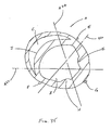
- Figure 35 is a schematic view of generally horizontal cross section of heart A including left ventricle B and right ventricle C. Also shown are left anterior descending artery E, posterior descending artery F, obtuse marginal artery G, postero-medial papillary muscle H and antero-lateral papillary muscle I. Shown in Figure 35 are three generally horizontal preferred alignments for tension member placement for the splints of the present invention. These alignments generally met three goals of splint positioning including good bisection of the left ventricle, avoidance of major coronary vessels and avoidance of valve apparatus including chordae leaflets and papillary muscles.
- Alignment 420 can be referred to as the anterior/posterior (AP) position.
- Alignment 422 can be referred as the posterior septal/lateral wall (PSL) position.
- Alignment 424 can be referred to as the anterior septal/lateral wall (ASL) position.
- the alignments shown illustrative only and that the alignments may be shifted or rotated about a vertical axis generally disposed through the left ventricle and still avoid the major coronary vessels and papillary muscles.
- the alignment passes through a substantial portion of right ventricle C, it may be desirable to dispose not only two pads on the exterior of the heart at opposite ends of a tension member, but also a third pad within right ventricle C on septum J.
- the spacing between the third pad and the pad disposed outside the heart proximate left ventricle B preferably defines the shape change of left ventricle B.
- Figure 36 is a view of a cylinder or idealized heart chamber 48 which is used to illustrate the reduction of wall stress in a heart chamber as a result of deployment of the splint in accordance with the present invention.
- the model used herein and the calculations related to this model are intended merely to illustrate the mechanism by which wall stress is reduced in the heart chamber. No effort is made herein to quantify the actual reduction which would be realized in any particular in vivo application.
- Figure 37 is a view of the idealized heart chamber 48 of Figure 36 wherein the chamber has been splinted along its length L such that a "figure eight" cross-section has been formed along the length thereof. It should be noted that the perimeter of the circular transverse cross-section of the chamber in Figure 36 is equal to the perimeter of the figure eight transverse cross-section of Figure 37 . For purposes of this model, opposite lobes of the figure in cross-section are assumed to be mirror images.
- Figure 38 shows various parameters of the Figure 1 cross-section of the splinted idealized heart chamber of Figure 37 .
- 1 is the length of the splint between opposite walls of the chamber
- R 2 is the radius of each lobe
- ⁇ is the angle between the two radii of one lobe which extends to opposite ends of the portion of the splint within chamber 48
- h is the height of the triangle formed by the two radii and the portion of the splint within the chamber 48 (R 1 is the radius of the cylinder of Figure 36 ).
- the wall tension T in the walls of the cylinder is 104.4 newtons.
- the wall tension T is 77.33 newtons.
- Figures 39 and 40 show a hypothetical distribution of wall tension T and pressure P for the figure eight cross-section. As ⁇ goes from 180° to 0°, tension T s in the splint goes from 0 to a 2T load where the chamber walls carry a T load.
- the chamber length L is a constant 10 cm
- the original radius R 1 is 4 cm
- the length 1 between the two pads as measured along the tension member is preferably 0.4 to about 0.8 and more preferably between about 0.5 to about 0.7 and most preferably about 0.6 times the distance along the length of the tension member at end diastole if the pads were not secured to the tension member and provided no resistance to expansion of the heart.
- tension member length can be found in U.S. 6,260,552 , entitled "Transventricular Implant Tools and Devices”.
Abstract
Description
- The present invention pertains to the field of apparatus for treatment of a failing heart. In particular, the apparatus of the present invention is directed toward reducing the wall stress in the failing heart.
- The syndrome of heart failure is a common course for the progression of many forms of heart disease. Heart failure may be considered to be the condition in which an abnormality of cardiac function is responsible for the inability of the heart to pump blood at a rate commensurate with the requirements of the metabolizing tissues, or can do so only at an abnormally elevated filling pressure. There are many specific disease processes that can lead to heart failure. Typically resulting in dilatation of the left ventricular chamber. Etiologies that can lead to this form of failure include idiopathic cardiomyopathy, viral cardiomyopathy, and ischemic cardiomyopathy.
- The process of ventricular dilatation is generally the result of chronic volume overload or specific damage to the myocardium. In a normal heart that is exposed to long term increased cardiac output requirements, for example, that of an athlete, there is an adaptive process of slight ventricular dilation and muscle myocyte hypertrophy. In this way, the heart fully compensates for the increased cardiac output requirements. With damage to the myocardium or chronic volume overload, however, there are increased requirements put on the contracting myocardium to such a level that this compensated state is never achieved and the heart continues to dilate.
- The basic problem with a large dilated left ventricle is that there is a significant increase in wall tension and/or stress both during diastolic filling and during systolic contraction. In a normal heart, the adaptation of muscle hypertrophy (thickening) and ventricular dilatation maintain a fairly constant wall tension for systolic contraction. However, in a failing heart, the ongoing dilatation is greater than the hypertrophy and the result is a rising wall tension requirement for systolic contraction. This is felt to be an ongoing insult to the muscle myocyte resulting in further muscle damage. The increase in wall stress is also true for diastolic filling. Additionally, because of the lack of cardiac output, there is generally a rise in ventricular filling pressure from several physiologic mechanisms. Moreover, in diastole there is both a diameter increase and a pressure increase over normal, both contributing to higher wall stress levels. The increase in diastolic wall stress is felt to be the primary contributor to ongoing dilatation of the chamber.
- Prior art treatments for heart failure fall into three generally categories. The first being pharmacological, for example, diuretics. The second being assist systems, for example, pumps. Finally, surgical treatments have been experimented with, which are described in more detail below.
- With respect to pharmacological treatments, diuretics have been used to reduce the workload of the heart by reducing blood volume and preload. Clinically, preload is defined in several ways including left ventricular end diastolic pressure (LVEDP), or left ventricular end diastolic volume (LVEDV). Physiologically, the preferred definition is the length of stretch of the sarcomere at end diastole. Diuretics reduce extra cellular fluid which builds in congestive heart failure patients increasing preload conditions. Nitrates, arteriolar vasodilators, angiotensin converting enzyme inhibitors have been used to treat heart failure through the reduction of cardiac workload through the reduction of afterload. Afterload may be defined as the tension or stress required in the wall of the ventricle during ejection. Inotropes like digoxin are cardiac glycosides and function to increase cardiac output by increasing the force and speed of cardiac muscle contraction. These drug therapies offer some beneficial effects but do not stop the progression of the disease.
- Assist devices include mechanical pumps. Mechanical pumps reduce the load on the heart by performing all or part of the pumping function normally done by the heart. Currently, mechanical pumps are used to sustain the patient while a donor heart for transplantation becomes available for the patient.
- There are at least three surgical procedures for treatment of heart failure: 1) heart transplant; 2) dynamic cardiomyoplasty; and 3) the Batista partial left ventriculectomy. Heart transplantation has serious limitations including restricted availability of organs and adverse effects of immunosuppressive therapies required following heart transplantation. Cardiomyoplasty includes wrapping the heart with skeletal muscle and electrically stimulating the muscle to contract synchronously with the heart in order to help the pumping function of the heart. The Batista partial left ventriculectomy includes surgically remodeling the left ventricle by removing a segment of the muscular wall. This procedure reduces the diameter of the dilated heart, which in turn reduces the loading of the heart. However, this extremely invasive procedure reduces muscle mass of the heart.
- Document
WO 98/29041 - The present invention pertains to a non-pharmacological, passive apparatus for the treatment of a failing heart. The device is configured to reduce the tension in the heart wall. It is believed to reverse, stop or slow the disease process of a failing heart as it reduces the energy consumption of the failing heart, decreases isovolumetric contraction, increases isotonic contraction (sarcomere shortening), which in turn increases stroke volume. The device reduces wall tension during diastole and systole.
- Those apparatus of the present invention which reduce heart wall stress by changing chamber wall geometry can be referred to as "splints". Splints can be grouped as either "full cycle splints" which engage the heart to produce a chamber shape change throughout the cardiac cycle, or "restrictive splints" which do not engage the heart wall at end systole to produce a chamber shape change.
- In one embodiment, the apparatus includes a tension member for drawing at least two walls of the heart chamber toward each other to reduce the radius or area of the heart chamber in at least one cross sectional plane. The tension member has anchoring members disposed at opposite ends for engagement with the heart or chamber wall.
- In yet another embodiment, a heart wall tension reduction apparatus is provided which includes a first tension member having two oppositely disposed ends and first and second elongate anchor members. A second tension member can be provided. One of the elongate anchors may be substituted for by two smaller anchors.
- In an alternate embodiment of the heart wall tension reduction apparatus, an elongate compression member can be provided. First and second elongate lever members preferably extend from opposite ends of the compression member. A tension member extends between the first and second lever members.
- The compression member of the above embodiment can be disposed exterior to, or internally of the heart. The tension member extends through the chamber or chambers to bias the lever members toward the heart.
- In yet another embodiment of a heart wall tension reduction apparatus in accordance with the present invention, a rigid elongate frame member is provided. The frame member can extend through one or more chambers of the heart. One or more cantilever members can be disposed at opposite ends of the frame member. Each cantilever member includes at least one atraumatic pad disposed thereon. The atraumatic pads disposed at opposite ends of the frame member can be biased toward each other to compress the heart chamber.
- One method of placing a heart wall tension apparatus or splint on a human heart, which does not form part of the invention, includes the step of extending a hollow needle through at least one chamber of the heart such that each end of the needle is external to the chamber. A flexible leader is connected to a first end of a tension member. A second end of the tension member is connected to an atraumatic pad. The leader is advanced through the needle from one end of the needle to the other. The leader is further advanced until the second end of the tension member is proximate the heart and the first end of the tension member is external to the heart. A second atraumatic pad is connected to the first end of the tension member such that the first and second atraumatic pads engage the heart.
- Yet another method of placing a heart wall tension apparatus on a heart, which does not form part of the invention, includes the step of extending a needle having a flexible tension member releasably connected thereto through at least one chamber of the heart such that opposite ends of the tension member are external to the chamber and exposed on opposite sides of the chamber. The needle is removed from the tension member. Then first and second atraumatic pads are connected to the tension member at opposite ends of the tension member.
-
-
Figure 1 is a transverse cross-section of the left and right ventricles of a human heart showing the placement of a splint in accordance with the present invention; -
Figure 2 is a transverse cross-section of the left and right ventricles of a human heart showing the placement of a balloon device not in accordance with the present invention; -
Figure 3 is a transverse cross-section of the left and right ventricles of a human heart showing the placement of an external compression frame structure not in accordance with the present invention; -
Figure 4 is a transverse cross-section of the left and right ventricles of a human heart showing a clamp not in accordance with the present invention; -
Figure 5 is a transverse cross-section of the left and right ventricles of a human heart showing a three tension member version of the splint ofFigure 1 ; -
Figure 6 is a transverse cross-section of the left and right ventricles of a human heart showing a two tension member version of the splint shown inFigure 1 ; -
Figure 7 is a vertical cross-sectional view of the left ventricle of a human heart showing an alternate version of the splint in accordance with the present invention; -
Figure 8 is an end of the splint shown inFigure 7 ; -
Figure 9 is a vertical cross-sectional view of a chamber of a human heart showing another alternative embodiment of the splint in accordance with the present invention; -
Figure 10 is a vertical cross-section of a chamber of a human heart showing another alternative configuration of splints in accordance with the present invention; -
Figure 11 is a vertical cross-sectional view of a chamber of a human heart showing another embodiment of a splint in accordance with the present invention; -
Figure 12 is a vertical cross-sectional view of a chamber of a human heart showing another embodiment of the splint in accordance with the present invention; -
Figure 13 is a vertical cross-sectional view of a chamber of a human heart showing a compression member version of the splint in accordance with the present invention; -
Figure 14 is a vertical cross-sectional view of a chamber of a human heart showing another version of the splint shown inFigure 13 ; -
Figure 15 is a vertical cross-sectional view of a chamber of a human heart showing a frame member version of the splint in accordance with the present invention; -
Figure 16 is an end view of the splint ofFigure 15 ; -
Figure 17 is a vertical cross-section of the left ventricle and atrium, the left ventricle having scar tissue; -
Figure 18 is a vertical cross-section of the heart ofFigure 17 showing the splint ofFigure 1 drawing the scar tissue toward the opposite wall of the left ventricle; -
Figure 19 is a vertical cross-section of the left ventricle and atrium of a human heart showing a version of the splint ofFigure 1 having an elongate anchor bar; -
Figure 20 is a side view of an undeployed hinged anchor member; -
Figure 21 is a side view of a deployed hinged anchor member ofFigure 10 ; -
Figure 22 is a cross-sectional view of an captured ball anchor member; -
Figure 23 is a perspective view of a cross bar anchor member; -
Figure 24 is a cross sectional view of an alternate anchor pad; -
Figure 25 is a cross sectional view of an alternate anchor pad; -
Figure 26 is a perspective view of yet another alternate embodiment of an anchor pad including an anchor pad loosening device; -
Figure 27 is a perspective view of a tension member clip; -
Figure 28 is a cross sectional view of an alternate embodiment of a tension member clip; -
Figure 29 is a cross sectional view of a heart including a tension member having a heat set end; -
Figure 30 is a cross sectional view of the pad including an envelope; -
Figure 31 shows the envelope ofFigure 30 ; -
Figure 32 is a side view of a multifilament twisted cable; -
Figure 33 is a cross sectional of the cable ofFigure 32 ; -
Figure 34 is a side of a multifilament braided tension member; -
Figure 35 is a schematic generally horizontal cross sectional view of the heart showing preferred tension member alignments; -
Figure 36 is a idealized cylindrical model of a left ventricle of a human heart; -
Figure 37 is a splinted model of the left ventricle ofFigure 14 ; -
Figure 38 is a transverse cross-sectional view ofFigure 15 showing various modeling parameters; -
Figure 39 is a transverse cross-section of the splinted left ventricle ofFigure 15 showing a hypothetical force distribution; and -
Figure 40 is a second transverse cross-sectional view of the model left ventricle ofFigure 15 showing a hypothetical force distribution. - Referring now to the drawings wherein like reference numerals refer to like elements throughout the several views,
Figure 1 shows a transverse cross-section of aleft ventricle 10 and aright ventricle 12 of ahuman heart 14. Extending through the left ventricle is asplint 16 including atension member 18 and oppositely disposed anchors 20.Splint 16 as shown inFigure 1 has been positioned to draw opposite walls ofleft ventricle 10 toward each other to reduce the "radius" of the left ventricular cross-section or the cross-sectional area thereof to reduce left ventricular wall stresses. It should be understood that although thesplint 16 and the alternative devices disclosed herein are described in relation to the left ventricle of a human heart, these devices could also be used to reduce the radius or cross-sectional area of the other chambers of a human heart in transverse or vertical directions, or at an angle between the transverse and vertical. - Those apparatus of the present invention which reduce heart wall stress by changing chamber wall geometry can be referred to as "splints". "Full cycle splints" engage the heart to produce a chamber shape change throughout the cardiac cycle. "Restrictive splints" do not engage the heart wall at end systole to produce a chamber shape change.
-
Figure 2 discloses a device not forming part of the present invention, wherein a balloon 200 is deployed adjacent the left ventricle. The size and degree of inflation of the balloon can be varied to reduce the radius or cross-sectional area ofleft ventricle 10 ofheart 14. -
Figure 3 shows yet another device not forming part of the present invention deployed with respect toleft ventricle 10 ofhuman heart 14. Here acompression frame structure 300 is engaged withheart 14 atatraumatic anchor pads 310. Acompression member 312 having anatraumatic surface 314 presses against a wall ofleft ventricle 10 to reduce the radius or cross-sectional area thereof. -
Figure 4 is a transverse cross-sectional view ofhuman heart 14 showing yet another device not forming part of the present invention. In this case aclamp 400 havingatraumatic anchor pads 410 biased toward each other is shown disposed on a wall ofleft ventricle 10. Here the radius or cross-sectional area ofleft ventricle 10 is reduced by clamping off the portion of the wall betweenpads 410.Pads 410 can be biased toward each other and/or can be held together by a locking device. - Each of the various embodiments of the present invention disclosed in
Figures 1 and 2 can be made from materials which can remain implanted in the human body indefinitely. Such biocompatible materials are well-known to those skilled in the art of clinical medical devices. -
Figure 5 shows an alternate embodiment of the splint ofFigure 1 referred to inFigure 5 by the numeral 116. Theembodiment 116 shown inFigure 5 includes three tension members 118 as opposed to asingle tension member 18 as shown inFigure 1. Figure 6 shows yet another embodiment of thesplint 216 having fourtension members 218. It is anticipated that in some patients, the disease process of the failing heart may be so advanced that three, four or more tension members may be desirable to reduce the heart wall stresses more substantially than possible with a single tension member as shown inFigure 1 . -
Figure 7 is a partial vertical cross-section ofhuman heart 14 showingleft ventricle 10. InFigure 7 , another splint embodiment 316 is shown having atension member 318 extending throughleft ventricle 10. On opposite ends oftension member 318 are disposed elongate anchors orpads 320.Figure 8 is an end view oftension member 318 showingelongate anchor 320. -
Figure 9 shows another embodiment of asplint 416 disposed in a partial vertical cross-section ofhuman heart 14.Splint 416 includes two elongate anchors orpads 420 similar to those shown inFigures 7 and 8 . InFigure 9 , however, twotension members 418 extend throughleft ventricle 10 to interconnectanchors 420 on opposite sides ofheart 14. -
Figure 10 is a vertical cross section ofheart 14 showingleft ventricle 10. In this case, twosplints 16 are disposed throughleft ventricle 10 and vertically spaced from each other to resemble the configuration ofFigure 9 . -
Figure 11 is a vertical cross sectional view of the left ventricle ofheart 14. Two alternate embodiment splints 516 are shown extending throughleft ventricle 10. Eachsplint 516 includes twotension members 518 interconnecting two anchors orpads 520. -
Figure 12 is yet another vertical cross sectional view ofleft ventricle 10 ofheart 14. Analternate embodiment 616 of the splint is shown extending throughleft ventricle 10.Splint 616 includes an elongate anchor pad 620 and two shorter anchors orpads 621.Splint 616 includes twotension members 618. Eachtension member 618 extends between anchors 620 andrespective anchors 621. -
Figure 13 is a vertical cross sectional view ofleft ventricle 10 ofheart 14. Asplint 50 is shown disposed onheart 14.Splint 50 includes acompression member 52 shown extending throughleft ventricle 10. Opposite ends ofcompression member 52 are disposed exterior toleft ventricle 10.Lever members 54 extend from each end ofcompression member 52 upwardly along the exterior surface ofventricle 10. Atension member 56 extends betweenlever members 54 tobias lever members 54 towardheart 14 to compresschamber 10.Compression member 52 should be substantially rigid, butlever members 54 and to somedegree compression member 52 should be flexible enough to allowtension member 56 to biaslever members 54 towardheart 14. Alternately,lever members 54 could be hinged tocompression member 52 such thatlever members 54 could pivot about the hinge when biased towardheart 14 bytension member 56. -
Figure 14 shows analternate embodiment 156 of the splint shown inFigure 13 . In thiscase lever members 154 are longer thanmembers 54 ascompression member 152 ofsplint 150 has been disposed to the exterior ofleft ventricle 10. -
Figure 15 is a vertical cross sectional view ofleft ventricle 10 ofheart 14. An alternate embodiment 250 of the splint is shown onheart 14. A preferably relativelyrigid frame member 256 extends throughventricle 10. Disposed on opposite ends offrame 256 arecantilever member 254. Disposed oncantilever members 254 areatraumatic pads 258.Cantilever members 254 can be positioned alongframe member 256 such thatatraumatic pads 258 press againstheart 14 to compresschamber 10.Figure 16 is an end view offrame member 256 showingcantilever members 254 andpads 258. - It should be understood that each of the embodiments described above should be formed from suitable biocompatible materials known to those skilled in the art. The tension members can be formed from flexible or relatively more rigid material. The compression members and frame member should be formed from generally rigid material which may flex under load, but generally hold its shape.
-
Figure 17 is a partial vertical cross-section ofhuman heart 14 showingleft ventricle 10 and leftatrium 22. As shown inFigure 17 ,heart 14 includes a region ofscar tissue 24 associated with an aneurysm or ischemia. As shown inFigure 17 , thescar tissue 24 increases the radius or cross-sectional area ofleft ventricle 10 in the region affected by the scar tissue. Such an increase in the radius or cross-sectional area of the left ventricle will result in greater wall stresses on the walls of the left ventricle. -
Figure 18 is a vertical cross-sectional view of theheart 14 as shown inFigure 17 , wherein asplint 16 has been placed to draw thescar tissue 24 toward an opposite wall ofleft ventricle 10. As a consequence of placingsplint 16, the radius or cross-sectional area of the left ventricle affected by thescar tissue 24 is reduced. The reduction of this radius or cross-sectional area results in reduction in the wall stress in the left ventricular wall and thus improves heart pumping efficiency. -
Figure 19 is a vertical cross-sectional view ofleft ventricle 10 and leftatrium 22 ofheart 14 in which asplint 16 has been placed. As shown inFigure 19 ,splint 16 includes analternative anchor 26. Theanchor 20 is preferably an elongate member having a length as shown inFigure 9 substantially greater than its width (not shown).Anchor bar 26 might be used to reduce the radius or cross-sectional area of the left ventricle in an instance where there is generalized enlargement ofleft ventricle 10 such as in idiopathic dilated cardiomyopathy. In such an instance,bar anchor 26 can distribute forces more widely thananchor 20. -
Figures 20 and 21 are side views of a hinged anchor 28 which could be substituted foranchors 20 in undeployed and deployed positions respectively. Anchor 28 as shown inFigure 20 includes twolegs 29 similar to baranchor 26. Hinged anchor 28 could include additional legs and the length of those legs could be varied to distribute the force over the surface of the heart wall. In addition there could be webbing between each of the legs to give anchor 28 an umbrella-like appearance. Preferably the webbing would be disposed on the surface of the legs which would be in contact with the heart wall. -
Figure 22 is a cross-sectional view of acapture ball anchor 30.Capture ball anchor 30 can be used in place ofanchor 20.Capture ball anchor 30 includes adisk portion 32 to distribute the force of the anchor on the heart wall, and arecess 34 for receiving aball 36 affixed to an end oftension member 18.Disk 32 andrecess 34 include a side groove which allowstension member 18 to be passed from an outside edge ofdisk 32 intorecess 34.Ball 36 can then be advanced intorecess 34 by drawingtension member 18 through anopening 38 inrecess 34opposite disk 32. -
Figure 23 is a perspective view of across bar anchor 40. Thecross bar anchor 40 can be used in place ofanchors 20. Theanchor 40 preferably includes a disk orpad portion 42 having across bar 44 extending over an opening 46 inpad 42.Tension member 18 can be extended through opening 46 and tied to crossbar 42 as shown. -
Figure 24 is a cross sectional view of an alternate embodiment ofanchor pad 340 in accordance with the present invention.Anchor pad 340 preferably includes a disc shapedpad portion 342. Discshape pad portion 342 includesside 343, which in use is disposed toward the heart. A conical aperture 348 having slopingsides 346 extends throughpad 342.Collet 344 is disposed within orifice 348. A threadedportion 350 ofcollet 344 extends from orifice 348opposite side 343, nut 352 is threaded over threadedportion 350.Lumen 345 extends throughcollet 344. Atension member 354 is shown extending throughlumen 345.Lumen 345 has a diameter such that when nut 352 is not tightened on threadedportion 350,tension member 354 can slide freely throughlumen 345. When nut 352 is tightened, it drawscollet 344 away fromside 343.Collet 344 is then pinched betweenwalls 346 of orifice 348. Whencollet 344 is pinched, the size oflumen 345 is reduced such thattension member 354 can no longer move freely withinlumen 345, fixing the position ofpad 340 ontension member 354. -
Figure 25 is a cross sectional view of an alternate embodiment ananchor pad 360 in accordance with the present invention.Anchor pad 360 includes a generally disc-shapedpad portion 362.Pad 362 includes a side 363 which when the pad is in use, is disposed toward the heart. Atension member lumen 364 extends throughpad 362.Lumen 364 preferably has a generally conical shapedportion 365 disposed toward side 363.Tension member 370 is shown disposed throughlumen 364 inFigure 25 .Pad 362 includes a threadedpassage 366 extending from an edge ofpad 362 tolumen 364. A set screw 368 is threaded intopassage 366. Set screw 368 can be tightened to engagetension member 370 to fix the position ofanchor pad 360. When set screw 368 is not tightened, the size oflumen 364 is preferably large enough thatanchor pad 360 can slide relatively freely overtension member 370. -
Figure 26 is a perspective view of yet another embodiment ofanchor pad 380 in accordance with the present invention.Anchor pad 380 preferably includes a generally disc-shaped pad portion 382 having a first side 383 which in use would be disposed toward the heart and a second side 385. Pad 382 as well aspads - A tension member fastener 384 is formed in pad 382 by cutting a series of grooves and apertures through pad 382 from side 385 to side 383. A
first groove 386 has a generally horseshoe shape.Second groove 388 extends between opposite portions of horseshoe shapedgroove 386 to form two oppositely disposedcantilever members 387. A relatively large aperture 394 is formed betweencantilever members 387 proximate their free ends. A second andsmaller aperture 390 is formed closer to the fixed ends ofcantilever members 387.Tension member 392 is shown extending throughaperture 390. - As shown in
Figure 26 ,tension member 392 is clamped betweencantilever members 387 such that the location of pad 382 is fixed alongtension member 392. Pad 382 can be released by using a spreadingdevice 396 to spreadcantilever members 387 apart. Spreadingdevice 396 includes handle 398 to spreadingarms 400 each having afinger 402.Fingers 402 can be placed within aperture 394 thenarms 400 andfingers 402 can be spread apart by pivoting them around a pin 404 such thatcantilevers 387 are spread apart and pad 382 can move freely alongtension member 392. It can be appreciated that althoughspreader 396 is shown extending transversely fromtension member 392, it could also be configured such thatfingers 402 do not curve transversely fromarms 400 and thusspreader 396 could be disposed parallel totension member 392. This would be particularly desirable in a situation whereanchor pad 380 was being placed through a port or window during a less invasive splint implantation procedure. It can be appreciated thatcantilever members 387 can be held apart such thatpad 380 can be moved alongtension member 392 by placement of a temporary wedge or pin ingroove 388. For example,grooves 388 may include an additional small aperture disposed betweenaperture 390 and aperture 394 into which a pin could be placed to holdopen members 387. When it is desired to fix the position ofanchor pad 380 ontension member 392,device 396 could be used to spreadcantilever members 387 to remove the pin. The cantilever members could then be released to engagetension member 392.Aperture 390 ofpad 380 can also include a conical portion disposed toward side 383 such asconical portion 365 ofpad 360. - Cantilever arms 384 are preferably configured such that they do not stress
tension member 392 beyond its elastic limit. It can also be appreciated that the force developed bycantilever members 387 impinging ontension member 392 is operator independent and defined by the geometry and material characteristics ofmembers 387. -
Figure 27 is a perspective view of ananchor pad 360 having atension member 370 extending therethrough. Afterpad 360 is secured totension member 370, that portion oftension member 370 which extends from the side ofanchor pad 360 opposite side 363 is preferably removed. This can be accomplished by trimmingtension member 370 withwire cutter 414 or scissors. Althoughanchor pad 360 is used here to illustrate trimmingtension member 370, it can be appreciated that in each of the embodiments disclosed herein there may be an excess portion of tension member extending from an anchor, which is preferably removed or trimmed. -
Figure 28 is a cross sectional view of analternate embodiment 420 of a tension member cutter.Device 420 includes an elongateouter tube 422 having adistal end 424.Tube 424 defines alumen 423 through which extends asecond tube 430 having a distal end 428. Extending distally from distal end 428 are two cuttingarms lumen 423 and transversely restrained bydistal end 424 ofouter tube 422. When unrestrained bydistal end 424,arms arm cutting element Elements Figure 28 . Atension member 370 extends betweenarms 424 and throughlumen 432 ofinner tube 430. Arepresentative anchor pad 360 is disposedadjacent elements Device 420 ofFigure 28 is particularly useful when trimming excess tension member using less invasive techniques as it can be readily advanced over a tension member through a port or window trocar. -
Figure 29 is a vertical cross sectional view of left ventricle B of heart A. Atransventricular splint 443 including atension member 370 andanchor pads 360 are shown disposed on heart A. To the left of heart A as shown in the figure is acoiled portion 442 oftension member 470. As an alternative to trimming an excess length of tension member,tension member 370 could be formed from a shape memory alloy such thatportion 442 could be preset to assume a coil shape when warmed to near body temperature. - Once the length of the tension member has been adjusted, the anchors are secured in place along the tension member and the excess length of tension member removed if desired, the anchor or anchor pads are preferably secured in place on the heart. The anchor or anchor pads are secured such that relatively movement between the anchors or anchor pads and the heart is limited to reduce abrasion of the heart wall. To secure the anchor or anchor pads to heart A, a biocompatible adhesive could be placed between the pad and the heart to adhere the pad to the heart. Alternately, apertures could be provided in the pad such that sutures could be extended through the apertures and into the heart to secure the pad. In addition to sutures, the pad could include threaded apertures into which anchor screws could be advanced through the pad and into the heart wall to secure the pad to the heart.
-
Figure 30 illustrates yet another alternative approach to securing the anchors or anchor pads to the heart surface.Figure 30 is a cross sectional view of ananchor pad 340 disposed on heartA. Anchor pad 340 is disposed within anenvelope 446.Envelope 446 includes abottom layer 447 disposed betweenanchor pad 340 and heart A and atop layer 448 disposed on the opposite side ofanchor pad 340.Layers 347 and 340 are held together bysutures 449.Bottom layer 447 is preferably a mesh or expanded PTFE which has a pore size or intranodial dimension sufficient to promote tissue ingrowth. The pore size is preferably between about 10 and about 100 microns and more preferably, between about 20 and about 40 microns. With respect to expanded PTFE, the intranodial dimension is preferably between about 10 to about 100 microns and more preferably between about 20 to about 40 microns. The top material could also be expanded PTFE or the like having a pore size which preferably does not promote ingrowth and thus resists adhesion to surrounding tissue. As an alternative embodiment, the pores could be formed directly in the pad surface. -
Envelope 446 would preferably be placed aroundpad 340 prior to placingpad 340 ontension member 354. Awindow 450 can be provided to provide access to nut 352 to secure pads totension member 354. After tightening nut 352,window 450 can be closed by suture 452.Figure 31 is a top view ofpad 340 andenvelope 446 ofFigure 30 . It can be appreciated that a similar envelope can be placed around the various anchor pads disclosed herein. The location of the window may have to vary, however, to provide access to the respective means for securing the anchor pads to the tension member. - The splints of the present invention can be implanted acutely or chronically. When the splints are implanted chronically, it is particularly important that the tension member or members be highly fatigue resistant. Typical materials for the tension member can include, among other biocompatible materials, stainless steel, titanium alloys, NiTi alloys such as Nitinol or elgiloy. In a preferred embodiment, the tension member is a wire having a diameter of between 0.005 to 0.035 inches in diameter or, more preferably, between 0.01 and 0.02 inches in diameter and, most preferably, about 0.014 inches in diameter. The length of the tension member between the pads is preferably about 0.6 to 4 inches, and more preferably, between about 1 to 3 inches and, most preferably, about 2 inches. To improve the fatigue resistance of the metallic tension members, their surface can be electro-polished, buffed or shot peened. Drawing or annealing of the metal will also improve fatigue resistance.
- The tension member, in a preferred embodiment, articulates with respect to the anchor pad to reduce bending of the tension member at the pad. This can be accomplished by a ball and socket joint shown in
Figure 22 , for example. The tension member itself can be made more flexible or bendable by providing a multi-filament tension member such as a braided or twisted wire cable tension member. A multifiber filament structure of numerous smaller wires can then easily, while reducing the stress level on any individual wire as compared to a solid wire of the same diameter as the multifilament bundle. Such a multi-filament tension member can be made from biocompatible materials such as, but not limited to, stainless steel, Nitinol, titanium alloys, LCP (liquid crystal polymer), Spectra™ fiber, kevlar fiber, or carbon fiber. In a preferred embodiment, the multi-filament structure is coated or covered to substantially seal the multi-filament structure. Coatings such as silicone, urethane or PTFE are preferred. -
Figure 32 is a side view of multifilament twistedcable 400.Cable 400 includes a plurality of wires orfilaments 402 twisted about the longitudinal axis ofcable 400.Figure 33 is a transverse cross sectional view ofcable 400. InFigure 33 ,cable 400 includes a surrounding coating 404 not shown inFigure 32 . -
Figure 34 is a side view of a braidedmultifilament tension member 410.Tension member 410 includes a plurality of filaments orwires 412. It can be appreciated that numerous braiding patterns are known to those skilled in the art of multifilament members. It is anticipated that in a preferred embodiment,braided member 410 can have an optional core of fibers running parallel to an elongate axis oftension member 410. In yet another preferred embodiment,tension member 410 could have a solid wire core extending parallel to and along the longitudinal axis oftension member 410. - The tension members and anchors or anchor pads are preferably bio-resistant, i.e., resistant to physiologic attack. To improve bio-resistance, tension member and/or anchors or anchor pads can be coated with carbon material such as glass, pyrolytic carbon, diamond or graphite, zirconium nitrate or oxide. Roughened or porous urethanes, silicone or polymer coatings or sheaths can be used to promote tissue ingrowth to create a biological seal. Hydrophilic and albumin coatings can also be used. Drugs incorporated into a binder coating can also be used to reduce biological attack on the splint and irritation of tissue by the splint. Such drugs include heparin, coumadin, antiinflammatory steroid or ASA-aspirin. The oxide layer of the underlying metal could also be optimized to improve bio-resistance. This is particularly true for stainless steel, titanium, or nickel titanium on which an oxide layer can be formed by heating the component to improve biocompatibility. Further coatings include calcium hydroxy appetite, beta tricalcium phosphate and aluminum oxide can be applied to the tension member. The tension member and/or pad or anchor pad can at least be, in part, formed from titanium to enhance electronegativity.
- The anchors or anchor pads and, particularly the tension members are biocompatible, preferably antithrombogenic and made to prevent hemolysis. The coatings used to enhance bio-resistance described above can generally be used to improve biocompatibility. Since the tension member is exposed to significant blood flows through the left ventricle, in a preferred embodiment, the tension member has a generally small size and shape elliptical cross sectional shape to reduce turbulence or drag over the tension member. If such elliptical, transverse cross section tension member were used, it can be appreciated that the narrow end would be preferably oriented toward the direction of blood flow. It is also desirable to select a tension member material and shape which would not vibrate at resonant frequency under the influence of blood flow.
- Where the tension member passes through the heart wall, various approaches can be taken to reduce or prevent bleeding. For example, the surface of the anchor or anchor pad and/or tension member in contact with the heart wall can be coated or include an ingrowth inducing covering such as collagen, dacron, expanded PTFE or a roughened/porous surface. A clotting inducing substance may also be bound to the tension member and/or anchor or anchor pads, such as avitene or collagen. It is also contemplated that the portion of the heart wall where the tension member passes through could be cauterized. In a preferred embodiment, the tissue can be cauterized by heating the tension member. A glue such as cyanoacrylate can also be disposed between the tension member and the heart wall to reduce or prevent bleeding from the heart wall. Mechanical means such as an O-ring or compression fitting could also be disposed between the heart wall and the tension member to reduce bleeding. A purse string suture can be placed on the heart, around the tension member adjacent the pad as well.
- The tension member is preferably flexible enough to allow for changing interface conditions between the heart and the splint, and alternating pad orientation throughout the cardiac cycle. The flexibility should be sufficient enough to avoid injury to the heart or bleeding. It is also preferable that if the heart were to contract sufficiently enough to put the tension member in compression that it would readily buckle. Buckling could be promoted by providing a ribbon shaped tension member, chain link tension member, thin wire tension member, bent tension member or multi-filament tension.
- The tension member is preferably radiopaque, echo cardiographic compatible, or MRI compatible or includes a marker which is radiopaque, echo compatible, or MRI compatible. The preferred locations for markers would include the center of the tension member and at the ends of the tension member disposed at the heart walls. The radiopaque markers could be gold or platinum or other biocompatible metal or heavy metal filled polymeric sleeves. With respect to echo compatible or MRI compatible tension members or markers, the tension or marker are preferably non-interfering or visible. Having radiopaque echo compatible or MRI compatible tension members or markers is particularly desirable for follow-up, non-invasive monitoring of the tension member after implantation. The presence of the tension member can be visualized and the distance between two or more markers measured. Integrity of the tension member can be confirmed as well.
- In a preferred embodiment, the tension member is not conductive to the action potential of muscle. This can be accomplished by insulating the tension member, anchor and/or anchor pad interface or fabricating the tension member anchor and/or anchor pad from a non-conductive metal such as titanium.
- In addition to monitoring the performance of the tension member by visualization techniques such as fluoroscopy or echo imagery, sensors can advantageously be incorporated into the splints. For example, a strain gauge can be disposed on a tension member to monitor the loading on the member in use. Strain can be related to load as known to those skilled in the art by developing a stress/strain relationship for a given tension member. The strain gauge can be connected by a biocompatible lead to a conventional monitoring device. A pressure gauge formed from, for example, piezo electric material can also be disposed on the tension member to monitor filling pressures or muscle contractility.
- In a preferred embodiment, a tension member can be slidably enclosed within a tube. If the tension member were to fail, the tube would contain the tension member therein.
- It is anticipated that the tension member could be connected to a pacing lead. In such an instance, if the tension member were conductive, pacing signals could be conveyed along the tension member from one heart wall to another.
- In use, the various embodiments of the present invention are placed in or adjacent the human heart to reduce the radius or cross-section area of at least one chamber of the heart. This is done to reduce wall stress or tension in the heart or chamber wall to slow, stop or reverse failure of the heart. In the case of the
splint 16 shown inFigure 1 , a cannula can be used to pierce both walls of the heart and one end of the splint can be advanced through the cannula from one side of the heart to the opposite side where an anchor can be affixed or deployed. Likewise, an anchor is affixed or deployed at the opposite end ofsplint 16. Additional procedures for splint placement are described in more detail inU.S. 6,260,552 , entitled "Transventricular Implant Tools and Devices". - It can be appreciated that the methods described above to advance the tension members through the ventricles, that do not form part of the invention, can be repeated to advance the desired number of tension members through the ventricle for a particular configuration. The length of the tension members can be determined based upon the size and condition of the patient's heart. It should also be noted that although the left ventricle has been referred to here for illustrative purposes, that the apparatus of this invention can also be used to splint multiple chambers of a patient's heart as well as the right ventricle or either atrium.
-
Figure 35 is a schematic view of generally horizontal cross section of heart A including left ventricle B and right ventricle C. Also shown are left anterior descending artery E, posterior descending artery F, obtuse marginal artery G, postero-medial papillary muscle H and antero-lateral papillary muscle I. Shown inFigure 35 are three generally horizontal preferred alignments for tension member placement for the splints of the present invention. These alignments generally met three goals of splint positioning including good bisection of the left ventricle, avoidance of major coronary vessels and avoidance of valve apparatus including chordae leaflets and papillary muscles.Alignment 420 can be referred to as the anterior/posterior (AP) position.Alignment 422 can be referred as the posterior septal/lateral wall (PSL) position.Alignment 424 can be referred to as the anterior septal/lateral wall (ASL) position. - It can be appreciated that the alignments shown illustrative only and that the alignments may be shifted or rotated about a vertical axis generally disposed through the left ventricle and still avoid the major coronary vessels and papillary muscles. When the alignment passes through a substantial portion of right ventricle C, it may be desirable to dispose not only two pads on the exterior of the heart at opposite ends of a tension member, but also a third pad within right ventricle C on septum J. The spacing between the third pad and the pad disposed outside the heart proximate left ventricle B preferably defines the shape change of left ventricle B. This will allow the spacing of the third pad relative to the pad disposed outside the heart proximate right ventricle C to define a shape change if any of right ventricle C in view of the spacing between those pads. With the alignments as shown in
Figure 35 , the third pad will be unnecessary. It is likely, however, that withalignments -
Figure 36 is a view of a cylinder oridealized heart chamber 48 which is used to illustrate the reduction of wall stress in a heart chamber as a result of deployment of the splint in accordance with the present invention. The model used herein and the calculations related to this model are intended merely to illustrate the mechanism by which wall stress is reduced in the heart chamber. No effort is made herein to quantify the actual reduction which would be realized in any particular in vivo application. -
Figure 37 is a view of theidealized heart chamber 48 ofFigure 36 wherein the chamber has been splinted along its length L such that a "figure eight" cross-section has been formed along the length thereof. It should be noted that the perimeter of the circular transverse cross-section of the chamber inFigure 36 is equal to the perimeter of the figure eight transverse cross-section ofFigure 37 . For purposes of this model, opposite lobes of the figure in cross-section are assumed to be mirror images. -
Figure 38 shows various parameters of theFigure 1 cross-section of the splinted idealized heart chamber ofFigure 37 . Where 1 is the length of the splint between opposite walls of the chamber, R2 is the radius of each lobe, θ is the angle between the two radii of one lobe which extends to opposite ends of the portion of the splint withinchamber 48 and h is the height of the triangle formed by the two radii and the portion of the splint within the chamber 48 (R1 is the radius of the cylinder ofFigure 36 ). These various parameters are related as follows:


- From these relationships, the area of the figure eight cross-section can be calculated by:

- Where
chamber 48 is unsplinted as shown inFigure 36 A1, the original cross-sectional area of the cylinder is equal to A2 where θ = 180°, h = 0 and 1 = 2R2. Volume equals A2 times length L and circumferential wall tension equals pressure within the chamber times R2 times the length L of the chamber. - Thus, for example, with an original cylindrical radius of four centimeters and a pressure within the chamber of 140 mm of mercury, the wall tension T in the walls of the cylinder is 104.4 newtons. When a 3.84 cm splint is placed as shown in
Figures 37 and38 such that 1 = 3.84 cm, the wall tension T is 77.33 newtons. -
Figures 39 and 40 show a hypothetical distribution of wall tension T and pressure P for the figure eight cross-section. As θ goes from 180° to 0°, tension Ts in the splint goes from 0 to a 2T load where the chamber walls carry a T load. - In yet another example, assuming that the chamber length L is a constant 10 cm, the original radius R1 is 4 cm, at a 140 mmHg the tension in the walls is 74.7 N. If a 4.5 cm splint is placed such that 1 = 4.5 cm, the wall tension will then be 52.8 N.
- When a splint is actually placed on the heart, along an alignment such as those shown in
Figure 35 , the length 1 between the two pads as measured along the tension member is preferably 0.4 to about 0.8 and more preferably between about 0.5 to about 0.7 and most preferably about 0.6 times the distance along the length of the tension member at end diastole if the pads were not secured to the tension member and provided no resistance to expansion of the heart. A more detailed discussion of tension member length can be found inU.S. 6,260,552 , entitled "Transventricular Implant Tools and Devices". - It will be understood that this disclosure, in many respects, is only illustrative. Changes may be made in details, particularly in matters of shape, size, material, and arrangement of parts without exceeding the scope of the invention. Accordingly, the scope of the invention is as defined in the language of the appended claims.
Claims (24)
- An apparatus (16) for placement in a heart, the apparatus comprising:an elongate member (18) having opposite ends; andan anchor (20) disposed at each end of the elongate member configured to engage a wall of the heart (14) so that the engaged walls remain in a noncontacting relationship, characterized in that at least one of the anchors (340) includes a first tissue-contacting surface (447) disposed on a first side of the anchor and having a mechanism capable of securing the anchor to the wall, the mechanism including a tissue ingrowth material, and a second non-tissue-contacting surface (448) disposed on a second side of the anchor and comprising a material that resists adhesion to tissue.
- The apparatus (16) of claim 1, wherein the mechanism further includes a biocompatible adhesive.
- The apparatus (16) of claim 1, wherein the tissue ingrowth material (447) is a mesh material and/or is formed essentially of expanded PTFE.
- The apparatus (16) of any of claims 1-3, wherein the anchor (340) includes a top layer of material (448) connected to the tissue ingrowth material.
- The apparatus (16) of claim 4, wherein the top layer (448) is formed essentially of PTFE.
- The apparatus (16) of claim 1, wherein the anchor (340) further includes an aperture extending through the anchor, the aperture being threaded to receive a screw for securing the anchor to the wall.
- The apparatus (16) of any of the preceding claims, wherein at least one anchor (340) includes a mechanism (352) capable of securing the member (354) to the anchors.
- The apparatus (16) of claim 7, wherein the mechanism includes a set screw (368) disposed within a passage (366) of the anchor (360).
- The apparatus (16) of any of the preceding claims, wherein the anchors (340) are disc-shaped pads.
- The apparatus (16) of any of the preceding claims, wherein the member (354) is formed essentially of a material chosen from stainless steel, a titanium alloy, a nickel titanium alloy, a shape memory alloy, polymeric fibre, and carbon fibre.
- The apparatus (16) of any of the preceding claims, wherein the member (354) has a length in the range of approximately 2.54 cm to approximately 10.15 cm.
- The apparatus (16) of any of the preceding claims, wherein the member (18) is a braided wire (410).
- The apparatus (16) of any of the preceding claims, wherein the member (18) is a twisted wire (400).
- The apparatus of any of the preceding claims, wherein the member (400) includes a coating (404).
- The apparatus (16) of claim 14, wherein the coating (404) is formed essentially from one of silicone, urethane, PTFE, and carbon.
- The apparatus (16) of claim 14, wherein the coating (404) includes a drug.
- The apparatus (16) of claim 14, wherein the coating (404) is tissue ingrowth inducing.
- The apparatus (16) of claim 14, wherein the coating (404) is formed essentially of collagen.
- The apparatus (16) of any of the preceding claims, wherein the member (18) includes a core fiber extending along an axis of the member.
- The apparatus (16) of any of the preceding claims, wherein the member (18) is radiopaque and/or echocardiograph compatible and/or MRI compatible.
- The apparatus (16) of any of the preceding claims further comprising a radiopaque marker and/or an echocardiograph compatible marker and/or a MRI compatible marker associated with the member (18).
- The apparatus (16) of any of the preceding claims, wherein the member (18) is configured to extend transverse the left ventricle of the heart and avoid papillary muscles and arteries.
- The apparatus (16) of claim 1, wherein the member (400) is a multifilament member.
- The apparatus (16) of claim 1, wherein the first tissue-contacting surface (447) and second non-tissue contacting surface (448) comprise an envelope that is configured to surround an inner anchor portion (340).
Applications Claiming Priority (3)
| Application Number | Priority Date | Filing Date | Title |
|---|---|---|---|
| US124286 | 1998-07-29 | ||
| US09/124,286 US6045497A (en) | 1997-01-02 | 1998-07-29 | Heart wall tension reduction apparatus and method |
| EP99937483A EP1143858A2 (en) | 1998-07-29 | 1999-07-27 | Heart wall tension reduction apparatus and method |
Related Parent Applications (2)
| Application Number | Title | Priority Date | Filing Date |
|---|---|---|---|
| EP99937483.8 Division | 1999-07-27 | ||
| EP99937483A Division EP1143858A2 (en) | 1998-07-29 | 1999-07-27 | Heart wall tension reduction apparatus and method |
Publications (2)
| Publication Number | Publication Date |
|---|---|
| EP1520519A1 EP1520519A1 (en) | 2005-04-06 |
| EP1520519B1 true EP1520519B1 (en) | 2010-03-24 |
Family
ID=22413941
Family Applications (2)
| Application Number | Title | Priority Date | Filing Date |
|---|---|---|---|
| EP04078441A Expired - Lifetime EP1520519B1 (en) | 1998-07-29 | 1999-07-27 | Heart wall tension reduction apparatus |
| EP99937483A Withdrawn EP1143858A2 (en) | 1998-07-29 | 1999-07-27 | Heart wall tension reduction apparatus and method |
Family Applications After (1)
| Application Number | Title | Priority Date | Filing Date |
|---|---|---|---|
| EP99937483A Withdrawn EP1143858A2 (en) | 1998-07-29 | 1999-07-27 | Heart wall tension reduction apparatus and method |
Country Status (6)
| Country | Link |
|---|---|
| US (3) | US6045497A (en) |
| EP (2) | EP1520519B1 (en) |
| AT (1) | ATE461661T1 (en) |
| AU (1) | AU5230899A (en) |
| DE (1) | DE69942183D1 (en) |
| WO (1) | WO2000006026A2 (en) |
Cited By (13)
| Publication number | Priority date | Publication date | Assignee | Title |
|---|---|---|---|---|
| US10856984B2 (en) | 2017-08-25 | 2020-12-08 | Neovasc Tiara Inc. | Sequentially deployed transcatheter mitral valve prosthesis |
| US10940001B2 (en) | 2012-05-30 | 2021-03-09 | Neovasc Tiara Inc. | Methods and apparatus for loading a prosthesis onto a delivery system |
| US11311376B2 (en) | 2019-06-20 | 2022-04-26 | Neovase Tiara Inc. | Low profile prosthetic mitral valve |
| US11357622B2 (en) | 2016-01-29 | 2022-06-14 | Neovase Tiara Inc. | Prosthetic valve for avoiding obstruction of outflow |
| US11389291B2 (en) | 2013-04-04 | 2022-07-19 | Neovase Tiara Inc. | Methods and apparatus for delivering a prosthetic valve to a beating heart |
| US11413139B2 (en) | 2011-11-23 | 2022-08-16 | Neovasc Tiara Inc. | Sequentially deployed transcatheter mitral valve prosthesis |
| US11419720B2 (en) | 2010-05-05 | 2022-08-23 | Neovasc Tiara Inc. | Transcatheter mitral valve prosthesis |
| US11464631B2 (en) | 2016-11-21 | 2022-10-11 | Neovasc Tiara Inc. | Methods and systems for rapid retraction of a transcatheter heart valve delivery system |
| US11491006B2 (en) | 2019-04-10 | 2022-11-08 | Neovasc Tiara Inc. | Prosthetic valve with natural blood flow |
| US11497602B2 (en) | 2012-02-14 | 2022-11-15 | Neovasc Tiara Inc. | Methods and apparatus for engaging a valve prosthesis with tissue |
| US11602429B2 (en) | 2019-04-01 | 2023-03-14 | Neovasc Tiara Inc. | Controllably deployable prosthetic valve |
| US11737872B2 (en) | 2018-11-08 | 2023-08-29 | Neovasc Tiara Inc. | Ventricular deployment of a transcatheter mitral valve prosthesis |
| US11779742B2 (en) | 2019-05-20 | 2023-10-10 | Neovasc Tiara Inc. | Introducer with hemostasis mechanism |
Families Citing this family (450)
| Publication number | Priority date | Publication date | Assignee | Title |
|---|---|---|---|---|
| US6090303A (en) * | 1991-06-27 | 2000-07-18 | Applied Materials, Inc. | Process for etching oxides in an electromagnetically coupled planar plasma apparatus |
| US5477975A (en) * | 1993-10-15 | 1995-12-26 | Applied Materials Inc | Plasma etch apparatus with heated scavenging surfaces |
| US6776754B1 (en) * | 2000-10-04 | 2004-08-17 | Wilk Patent Development Corporation | Method for closing off lower portion of heart ventricle |
| US7494507B2 (en) * | 2000-01-30 | 2009-02-24 | Diamicron, Inc. | Articulating diamond-surfaced spinal implants |
| US6596225B1 (en) | 2000-01-31 | 2003-07-22 | Diamicron, Inc. | Methods for manufacturing a diamond prosthetic joint component |
| US6425922B1 (en) | 2000-01-30 | 2002-07-30 | Diamicron, Inc. | Prosthetic hip joint having at least one sintered polycrystalline diamond compact articulation surface |
| US6676704B1 (en) | 1994-08-12 | 2004-01-13 | Diamicron, Inc. | Prosthetic joint component having at least one sintered polycrystalline diamond compact articulation surface and substrate surface topographical features in said polycrystalline diamond compact |
| US6494918B1 (en) | 2000-01-30 | 2002-12-17 | Diamicron, Inc. | Component for a prosthetic joint having a diamond load bearing and articulation surface |
| US6800095B1 (en) | 1994-08-12 | 2004-10-05 | Diamicron, Inc. | Diamond-surfaced femoral head for use in a prosthetic joint |
| US6517583B1 (en) | 2000-01-30 | 2003-02-11 | Diamicron, Inc. | Prosthetic hip joint having a polycrystalline diamond compact articulation surface and a counter bearing surface |
| US6592619B2 (en) | 1996-01-02 | 2003-07-15 | University Of Cincinnati | Heart wall actuation device for the natural heart |
| US5957977A (en) | 1996-01-02 | 1999-09-28 | University Of Cincinnati | Activation device for the natural heart including internal and external support structures |
| US6520904B1 (en) | 1996-01-02 | 2003-02-18 | The University Of Cincinnati | Device and method for restructuring heart chamber geometry |
| US6123662A (en) * | 1998-07-13 | 2000-09-26 | Acorn Cardiovascular, Inc. | Cardiac disease treatment and device |
| US6045497A (en) | 1997-01-02 | 2000-04-04 | Myocor, Inc. | Heart wall tension reduction apparatus and method |
| US6050936A (en) | 1997-01-02 | 2000-04-18 | Myocor, Inc. | Heart wall tension reduction apparatus |
| US20030045771A1 (en) * | 1997-01-02 | 2003-03-06 | Schweich Cyril J. | Heart wall tension reduction devices and methods |
| US6183411B1 (en) | 1998-09-21 | 2001-02-06 | Myocor, Inc. | External stress reduction device and method |
| US6406420B1 (en) * | 1997-01-02 | 2002-06-18 | Myocor, Inc. | Methods and devices for improving cardiac function in hearts |
| US6077214A (en) * | 1998-07-29 | 2000-06-20 | Myocor, Inc. | Stress reduction apparatus and method |
| US7883539B2 (en) | 1997-01-02 | 2011-02-08 | Edwards Lifesciences Llc | Heart wall tension reduction apparatus and method |
| DE19826675A1 (en) | 1997-06-21 | 1999-03-04 | Haindl Hans | Bag for shrouding the heart |
| US6168570B1 (en) * | 1997-12-05 | 2001-01-02 | Micrus Corporation | Micro-strand cable with enhanced radiopacity |
| US6332893B1 (en) * | 1997-12-17 | 2001-12-25 | Myocor, Inc. | Valve to myocardium tension members device and method |
| US6190408B1 (en) | 1998-03-05 | 2001-02-20 | The University Of Cincinnati | Device and method for restructuring the heart chamber geometry |
| DE19831699C1 (en) * | 1998-07-15 | 2000-04-27 | Caremed Medical Produkte Ag | Implant holder |
| US6260552B1 (en) * | 1998-07-29 | 2001-07-17 | Myocor, Inc. | Transventricular implant tools and devices |
| US8715156B2 (en) * | 1998-10-09 | 2014-05-06 | Swaminathan Jayaraman | Modification of properties and geometry of heart tissue to influence function |
| US6685627B2 (en) | 1998-10-09 | 2004-02-03 | Swaminathan Jayaraman | Modification of properties and geometry of heart tissue to influence heart function |
| US6360749B1 (en) | 1998-10-09 | 2002-03-26 | Swaminathan Jayaraman | Modification of properties and geometry of heart tissue to influence heart function |
| US6358198B1 (en) * | 1999-05-18 | 2002-03-19 | John M. Levin | Laparoscopic/thorascopic support device |
| US7618426B2 (en) * | 2002-12-11 | 2009-11-17 | Usgi Medical, Inc. | Apparatus and methods for forming gastrointestinal tissue approximations |
| US7416554B2 (en) * | 2002-12-11 | 2008-08-26 | Usgi Medical Inc | Apparatus and methods for forming and securing gastrointestinal tissue folds |
| US7744613B2 (en) | 1999-06-25 | 2010-06-29 | Usgi Medical, Inc. | Apparatus and methods for forming and securing gastrointestinal tissue folds |
| US7637905B2 (en) | 2003-01-15 | 2009-12-29 | Usgi Medical, Inc. | Endoluminal tool deployment system |
| SE514718C2 (en) * | 1999-06-29 | 2001-04-09 | Jan Otto Solem | Apparatus for treating defective closure of the mitral valve apparatus |
| US6997951B2 (en) * | 1999-06-30 | 2006-02-14 | Edwards Lifesciences Ag | Method and device for treatment of mitral insufficiency |
| US8500795B2 (en) * | 1999-08-09 | 2013-08-06 | Cardiokinetix, Inc. | Retrievable devices for improving cardiac function |
| US8529430B2 (en) | 2002-08-01 | 2013-09-10 | Cardiokinetix, Inc. | Therapeutic methods and devices following myocardial infarction |
| US9694121B2 (en) | 1999-08-09 | 2017-07-04 | Cardiokinetix, Inc. | Systems and methods for improving cardiac function |
| US7303526B2 (en) * | 1999-08-09 | 2007-12-04 | Cardiokinetix, Inc. | Device for improving cardiac function |
| US8388672B2 (en) | 1999-08-09 | 2013-03-05 | Cardiokinetix, Inc. | System for improving cardiac function by sealing a partitioning membrane within a ventricle |
| US20060229491A1 (en) * | 2002-08-01 | 2006-10-12 | Cardiokinetix, Inc. | Method for treating myocardial rupture |
| US7582051B2 (en) * | 2005-06-10 | 2009-09-01 | Cardiokinetix, Inc. | Peripheral seal for a ventricular partitioning device |
| US7674222B2 (en) * | 1999-08-09 | 2010-03-09 | Cardiokinetix, Inc. | Cardiac device and methods of use thereof |
| US8257428B2 (en) * | 1999-08-09 | 2012-09-04 | Cardiokinetix, Inc. | System for improving cardiac function |
| US10307147B2 (en) | 1999-08-09 | 2019-06-04 | Edwards Lifesciences Corporation | System for improving cardiac function by sealing a partitioning membrane within a ventricle |
| US20030109770A1 (en) * | 1999-08-09 | 2003-06-12 | Sharkey Hugh R. | Device with a porous membrane for improving cardiac function |
| US6387104B1 (en) | 1999-11-12 | 2002-05-14 | Scimed Life Systems, Inc. | Method and apparatus for endoscopic repair of the lower esophageal sphincter |
| US6702732B1 (en) | 1999-12-22 | 2004-03-09 | Paracor Surgical, Inc. | Expandable cardiac harness for treating congestive heart failure |
| US6709463B1 (en) | 2000-01-30 | 2004-03-23 | Diamicron, Inc. | Prosthetic joint component having at least one solid polycrystalline diamond component |
| US7296577B2 (en) * | 2000-01-31 | 2007-11-20 | Edwards Lifescience Ag | Transluminal mitral annuloplasty with active anchoring |
| US6989028B2 (en) | 2000-01-31 | 2006-01-24 | Edwards Lifesciences Ag | Medical system and method for remodeling an extravascular tissue structure |
| US6402781B1 (en) * | 2000-01-31 | 2002-06-11 | Mitralife | Percutaneous mitral annuloplasty and cardiac reinforcement |
| WO2001067985A1 (en) * | 2000-03-10 | 2001-09-20 | Paracor Surgical, Inc. | Expandable cardiac harness for treating congestive heart failure |
| US6537198B1 (en) | 2000-03-21 | 2003-03-25 | Myocor, Inc. | Splint assembly for improving cardiac function in hearts, and method for implanting the splint assembly |
| US8622739B2 (en) * | 2001-05-09 | 2014-01-07 | Ben-Zion Karmon | Method for enlarging a jaw bone using a hollow dental implant having a side perforation |
| US7771482B1 (en) * | 2000-05-09 | 2010-08-10 | Ben-Zion Karmon | Method for tissue expansion and regeneration using bioresorbable inflatable devices |
| US6425856B1 (en) | 2000-05-10 | 2002-07-30 | Acorn Cardiovascular, Inc. | Cardiac disease treatment and device |
| US20050095268A1 (en) * | 2000-06-12 | 2005-05-05 | Acorn Cardiovascular, Inc. | Cardiac wall tension relief with cell loss management |
| US6902522B1 (en) | 2000-06-12 | 2005-06-07 | Acorn Cardiovascular, Inc. | Cardiac disease treatment and device |
| US6730016B1 (en) * | 2000-06-12 | 2004-05-04 | Acorn Cardiovascular, Inc. | Cardiac disease treatment and device |
| US6951534B2 (en) * | 2000-06-13 | 2005-10-04 | Acorn Cardiovascular, Inc. | Cardiac support device |
| US6482146B1 (en) * | 2000-06-13 | 2002-11-19 | Acorn Cardiovascular, Inc. | Cardiac disease treatment and device |
| US6343605B1 (en) | 2000-08-08 | 2002-02-05 | Scimed Life Systems, Inc. | Percutaneous transluminal myocardial implantation device and method |
| US7862500B2 (en) * | 2002-08-01 | 2011-01-04 | Cardiokinetix, Inc. | Multiple partitioning devices for heart treatment |
| US10064696B2 (en) | 2000-08-09 | 2018-09-04 | Edwards Lifesciences Corporation | Devices and methods for delivering an endocardial device |
| US9332993B2 (en) | 2004-08-05 | 2016-05-10 | Cardiokinetix, Inc. | Devices and methods for delivering an endocardial device |
| US9078660B2 (en) * | 2000-08-09 | 2015-07-14 | Cardiokinetix, Inc. | Devices and methods for delivering an endocardial device |
| US7762943B2 (en) * | 2004-03-03 | 2010-07-27 | Cardiokinetix, Inc. | Inflatable ventricular partitioning device |
| US9332992B2 (en) | 2004-08-05 | 2016-05-10 | Cardiokinetix, Inc. | Method for making a laminar ventricular partitioning device |
| US20060030881A1 (en) | 2004-08-05 | 2006-02-09 | Cardiokinetix, Inc. | Ventricular partitioning device |
| US8398537B2 (en) * | 2005-06-10 | 2013-03-19 | Cardiokinetix, Inc. | Peripheral seal for a ventricular partitioning device |
| US7399271B2 (en) * | 2004-01-09 | 2008-07-15 | Cardiokinetix, Inc. | Ventricular partitioning device |
| US6887192B1 (en) | 2000-09-08 | 2005-05-03 | Converge Medical, Inc. | Heart support to prevent ventricular remodeling |
| US8956407B2 (en) * | 2000-09-20 | 2015-02-17 | Mvrx, Inc. | Methods for reshaping a heart valve annulus using a tensioning implant |
| US20090287179A1 (en) | 2003-10-01 | 2009-11-19 | Ample Medical, Inc. | Devices, systems, and methods for reshaping a heart valve annulus, including the use of magnetic tools |
| US20060106279A1 (en) | 2004-05-14 | 2006-05-18 | Ample Medical, Inc. | Devices, systems, and methods for reshaping a heart valve annulus, including the use of a bridge implant having an adjustable bridge stop |
| US20050228422A1 (en) * | 2002-11-26 | 2005-10-13 | Ample Medical, Inc. | Devices, systems, and methods for reshaping a heart valve annulus, including the use of magnetic tools |
| US20050222489A1 (en) | 2003-10-01 | 2005-10-06 | Ample Medical, Inc. | Devices, systems, and methods for reshaping a heart valve annulus, including the use of a bridge implant |
| US20080091264A1 (en) | 2002-11-26 | 2008-04-17 | Ample Medical, Inc. | Devices, systems, and methods for reshaping a heart valve annulus, including the use of magnetic tools |
| US20060106278A1 (en) * | 2004-05-14 | 2006-05-18 | Ample Medical, Inc. | Devices, systems, and methods for reshaping a heart valve annulus, including the use of an adjustable bridge implant system |
| US8784482B2 (en) * | 2000-09-20 | 2014-07-22 | Mvrx, Inc. | Method of reshaping a heart valve annulus using an intravascular device |
| US6616684B1 (en) * | 2000-10-06 | 2003-09-09 | Myocor, Inc. | Endovascular splinting devices and methods |
| US6723038B1 (en) | 2000-10-06 | 2004-04-20 | Myocor, Inc. | Methods and devices for improving mitral valve function |
| US6564094B2 (en) | 2000-12-22 | 2003-05-13 | Acorn Cardiovascular, Inc. | Cardiac disease treatment and device |
| US6810882B2 (en) | 2001-01-30 | 2004-11-02 | Ev3 Santa Rosa, Inc. | Transluminal mitral annuloplasty |
| US7510576B2 (en) * | 2001-01-30 | 2009-03-31 | Edwards Lifesciences Ag | Transluminal mitral annuloplasty |
| DE20220502U1 (en) * | 2001-03-23 | 2003-10-02 | Alcove Surfaces Gmbh | implant |
| US6622730B2 (en) | 2001-03-30 | 2003-09-23 | Myocor, Inc. | Device for marking and aligning positions on the heart |
| US6923646B2 (en) * | 2001-04-18 | 2005-08-02 | Air Techniques, Inc. | Process and apparatus for treating an exhaust stream from a dental operatory |
| US8202315B2 (en) | 2001-04-24 | 2012-06-19 | Mitralign, Inc. | Catheter-based annuloplasty using ventricularly positioned catheter |
| US7346394B2 (en) * | 2001-04-27 | 2008-03-18 | Cardiac Pacemakers, Inc. | Cardiac stimulation at high ventricular wall stress areas |
| DE60227676D1 (en) | 2001-09-07 | 2008-08-28 | Mardil Inc | METHOD AND DEVICE FOR EXTERNAL HEART STABILIZATION |
| WO2003022176A2 (en) * | 2001-09-10 | 2003-03-20 | Paracor Medical, Inc. | Cardiac harness |
| US7060023B2 (en) | 2001-09-25 | 2006-06-13 | The Foundry Inc. | Pericardium reinforcing devices and methods of using them |
| US6685620B2 (en) * | 2001-09-25 | 2004-02-03 | The Foundry Inc. | Ventricular infarct assist device and methods for using it |
| US6695769B2 (en) | 2001-09-25 | 2004-02-24 | The Foundry, Inc. | Passive ventricular support devices and methods of using them |
| EP1434542A2 (en) * | 2001-10-01 | 2004-07-07 | Ample Medical, Inc. | Methods and devices for heart valve treatments |
| US7144363B2 (en) * | 2001-10-16 | 2006-12-05 | Extensia Medical, Inc. | Systems for heart treatment |
| GB0125925D0 (en) * | 2001-10-29 | 2001-12-19 | Univ Glasgow | Mitral valve prosthesis |
| WO2003037217A1 (en) * | 2001-10-31 | 2003-05-08 | Paracor Medical, Inc. | Heart failure treatment device |
| US7635387B2 (en) * | 2001-11-01 | 2009-12-22 | Cardiac Dimensions, Inc. | Adjustable height focal tissue deflector |
| US6824562B2 (en) | 2002-05-08 | 2004-11-30 | Cardiac Dimensions, Inc. | Body lumen device anchor, device and assembly |
| US6908478B2 (en) * | 2001-12-05 | 2005-06-21 | Cardiac Dimensions, Inc. | Anchor and pull mitral valve device and method |
| US6976995B2 (en) * | 2002-01-30 | 2005-12-20 | Cardiac Dimensions, Inc. | Fixed length anchor and pull mitral valve device and method |
| US7179282B2 (en) * | 2001-12-05 | 2007-02-20 | Cardiac Dimensions, Inc. | Device and method for modifying the shape of a body organ |
| US7174896B1 (en) | 2002-01-07 | 2007-02-13 | Paracor Medical, Inc. | Method and apparatus for supporting a heart |
| US7022063B2 (en) | 2002-01-07 | 2006-04-04 | Paracor Medical, Inc. | Cardiac harness |
| US6764510B2 (en) | 2002-01-09 | 2004-07-20 | Myocor, Inc. | Devices and methods for heart valve treatment |
| US7351260B2 (en) | 2005-01-20 | 2008-04-01 | Cardiac Dimensions, Inc. | Tissue shaping device |
| US7181272B2 (en) | 2002-04-22 | 2007-02-20 | Medtronic, Inc. | Cardiac restraint with electrode attachment sites |
| US8641727B2 (en) * | 2002-06-13 | 2014-02-04 | Guided Delivery Systems, Inc. | Devices and methods for heart valve repair |
| US7883538B2 (en) * | 2002-06-13 | 2011-02-08 | Guided Delivery Systems Inc. | Methods and devices for termination |
| US7666193B2 (en) * | 2002-06-13 | 2010-02-23 | Guided Delivery Sytems, Inc. | Delivery devices and methods for heart valve repair |
| US9226825B2 (en) * | 2002-06-13 | 2016-01-05 | Guided Delivery Systems, Inc. | Delivery devices and methods for heart valve repair |
| US7753858B2 (en) * | 2002-06-13 | 2010-07-13 | Guided Delivery Systems, Inc. | Delivery devices and methods for heart valve repair |
| US20060122633A1 (en) * | 2002-06-13 | 2006-06-08 | John To | Methods and devices for termination |
| US7758637B2 (en) * | 2003-02-06 | 2010-07-20 | Guided Delivery Systems, Inc. | Delivery devices and methods for heart valve repair |
| US9949829B2 (en) | 2002-06-13 | 2018-04-24 | Ancora Heart, Inc. | Delivery devices and methods for heart valve repair |
| US20040243227A1 (en) * | 2002-06-13 | 2004-12-02 | Guided Delivery Systems, Inc. | Delivery devices and methods for heart valve repair |
| US8287555B2 (en) * | 2003-02-06 | 2012-10-16 | Guided Delivery Systems, Inc. | Devices and methods for heart valve repair |
| US7753922B2 (en) * | 2003-09-04 | 2010-07-13 | Guided Delivery Systems, Inc. | Devices and methods for cardiac annulus stabilization and treatment |
| US7081084B2 (en) * | 2002-07-16 | 2006-07-25 | University Of Cincinnati | Modular power system and method for a heart wall actuation system for the natural heart |
| US20040059180A1 (en) * | 2002-09-23 | 2004-03-25 | The University Of Cincinnati | Basal mounting cushion frame component to facilitate extrinsic heart wall actuation |
| US7850729B2 (en) | 2002-07-18 | 2010-12-14 | The University Of Cincinnati | Deforming jacket for a heart actuation device |
| US6988982B2 (en) * | 2002-08-19 | 2006-01-24 | Cardioenergetics | Heart wall actuation system for the natural heart with shape limiting elements |
| EP1534173A2 (en) * | 2002-09-05 | 2005-06-01 | Paracor Medical, Inc. | Cardiac harness |
| AU2003277118A1 (en) * | 2002-10-01 | 2004-04-23 | Ample Medical, Inc. | Devices for retaining native heart valve leaflet |
| CN100553590C (en) * | 2002-10-01 | 2009-10-28 | 安普尔医药公司 | The device of finishing semilunar valve annulus |
| AU2003277115A1 (en) * | 2002-10-01 | 2004-04-23 | Ample Medical, Inc. | Device and method for repairing a native heart valve leaflet |
| US7087064B1 (en) * | 2002-10-15 | 2006-08-08 | Advanced Cardiovascular Systems, Inc. | Apparatuses and methods for heart valve repair |
| CA2500512A1 (en) | 2002-10-21 | 2004-05-06 | Mitralign Incorporated | Method and apparatus for performing catheter-based annuloplasty using local plications |
| US8979923B2 (en) | 2002-10-21 | 2015-03-17 | Mitralign, Inc. | Tissue fastening systems and methods utilizing magnetic guidance |
| US7112219B2 (en) | 2002-11-12 | 2006-09-26 | Myocor, Inc. | Devices and methods for heart valve treatment |
| AU2003279506A1 (en) * | 2002-11-12 | 2004-06-03 | Regenex Ltd. | Expandable devices and methods for tissue expansion, regenerationand fixation |
| US7247134B2 (en) | 2002-11-12 | 2007-07-24 | Myocor, Inc. | Devices and methods for heart valve treatment |
| US7981152B1 (en) | 2004-12-10 | 2011-07-19 | Advanced Cardiovascular Systems, Inc. | Vascular delivery system for accessing and delivering devices into coronary sinus and other vascular sites |
| US20050059855A1 (en) * | 2002-11-15 | 2005-03-17 | Lilip Lau | Cardiac harness delivery device and method |
| US7736299B2 (en) * | 2002-11-15 | 2010-06-15 | Paracor Medical, Inc. | Introducer for a cardiac harness delivery |
| US20040098116A1 (en) | 2002-11-15 | 2004-05-20 | Callas Peter L. | Valve annulus constriction apparatus and method |
| US7485143B2 (en) * | 2002-11-15 | 2009-02-03 | Abbott Cardiovascular Systems Inc. | Apparatuses and methods for heart valve repair |
| US7404824B1 (en) | 2002-11-15 | 2008-07-29 | Advanced Cardiovascular Systems, Inc. | Valve aptation assist device |
| US9149602B2 (en) | 2005-04-22 | 2015-10-06 | Advanced Cardiovascular Systems, Inc. | Dual needle delivery system |
| US20070255093A1 (en) * | 2002-11-15 | 2007-11-01 | Lilip Lau | Cardiac harness delivery device and method |
| US8187324B2 (en) | 2002-11-15 | 2012-05-29 | Advanced Cardiovascular Systems, Inc. | Telescoping apparatus for delivering and adjusting a medical device in a vessel |
| US7335213B1 (en) | 2002-11-15 | 2008-02-26 | Abbott Cardiovascular Systems Inc. | Apparatus and methods for heart valve repair |
| US6945978B1 (en) | 2002-11-15 | 2005-09-20 | Advanced Cardiovascular Systems, Inc. | Heart valve catheter |
| US7189203B2 (en) * | 2002-11-15 | 2007-03-13 | Paracor Medical, Inc. | Cardiac harness delivery device and method |
| US7331972B1 (en) | 2002-11-15 | 2008-02-19 | Abbott Cardiovascular Systems Inc. | Heart valve chord cutter |
| US7837729B2 (en) * | 2002-12-05 | 2010-11-23 | Cardiac Dimensions, Inc. | Percutaneous mitral valve annuloplasty delivery system |
| US7942898B2 (en) | 2002-12-11 | 2011-05-17 | Usgi Medical, Inc. | Delivery systems and methods for gastric reduction |
| US7942884B2 (en) | 2002-12-11 | 2011-05-17 | Usgi Medical, Inc. | Methods for reduction of a gastric lumen |
| US6984242B2 (en) * | 2002-12-20 | 2006-01-10 | Gore Enterprise Holdings, Inc. | Implantable medical device assembly |
| EP1589873B1 (en) * | 2003-01-29 | 2011-12-21 | Roche Diagnostics GmbH | Integrated lancing test strip |
| US7314485B2 (en) * | 2003-02-03 | 2008-01-01 | Cardiac Dimensions, Inc. | Mitral valve device using conditioned shape memory alloy |
| US20050283042A1 (en) * | 2003-03-28 | 2005-12-22 | Steve Meyer | Cardiac harness having radiopaque coating and method of use |
| US20040249242A1 (en) * | 2003-03-28 | 2004-12-09 | Lilip Lau | Multi-panel cardiac harness |
| US20040220654A1 (en) * | 2003-05-02 | 2004-11-04 | Cardiac Dimensions, Inc. | Device and method for modifying the shape of a body organ |
| US7341584B1 (en) | 2003-05-30 | 2008-03-11 | Thomas David Starkey | Device and method to limit filling of the heart |
| US7887582B2 (en) * | 2003-06-05 | 2011-02-15 | Cardiac Dimensions, Inc. | Device and method for modifying the shape of a body organ |
| US20060178551A1 (en) * | 2003-06-09 | 2006-08-10 | Melvin David B | Securement system for a heart actuation device |
| WO2004110553A1 (en) | 2003-06-09 | 2004-12-23 | The University Of Cincinnati | Actuation mechanisms for a heart actuation device |
| WO2004110257A2 (en) | 2003-06-09 | 2004-12-23 | The University Of Cincinnati | Power system for a heart actuation device |
| US20060282161A1 (en) * | 2003-06-20 | 2006-12-14 | Medtronic Vascular, Inc. | Valve annulus reduction system |
| US7316706B2 (en) * | 2003-06-20 | 2008-01-08 | Medtronic Vascular, Inc. | Tensioning device, system, and method for treating mitral valve regurgitation |
| JP2007528749A (en) * | 2003-07-10 | 2007-10-18 | パラコー メディカル インコーポレイテッド | Self-fixing cardiac harness |
| US8216252B2 (en) | 2004-05-07 | 2012-07-10 | Usgi Medical, Inc. | Tissue manipulation and securement system |
| US7998112B2 (en) | 2003-09-30 | 2011-08-16 | Abbott Cardiovascular Systems Inc. | Deflectable catheter assembly and method of making same |
| US8007514B2 (en) * | 2003-10-17 | 2011-08-30 | St. Jude Medical Puerto Rico Llc | Automatic suture locking device |
| US7155295B2 (en) * | 2003-11-07 | 2006-12-26 | Paracor Medical, Inc. | Cardiac harness for treating congestive heart failure and for defibrillating and/or pacing/sensing |
| US20070106359A1 (en) * | 2003-11-07 | 2007-05-10 | Alan Schaer | Cardiac harness assembly for treating congestive heart failure and for pacing/sensing |
| US20070055091A1 (en) * | 2004-12-02 | 2007-03-08 | Lilip Lau | Cardiac harness for treating congestive heart failure and for defibrillating and/or pacing/sensing |
| US20070106336A1 (en) * | 2003-11-07 | 2007-05-10 | Alan Schaer | Cardiac harness assembly for treating congestive heart failure and for pacing/sensing |
| US20050171589A1 (en) * | 2003-11-07 | 2005-08-04 | Lilip Lau | Cardiac harness and method of delivery by minimally invasive access |
| US7158839B2 (en) * | 2003-11-07 | 2007-01-02 | Paracor Medical, Inc. | Cardiac harness for treating heart disease |
| WO2005046520A2 (en) * | 2003-11-07 | 2005-05-26 | Mayo Foundation For Medical Education And Research | Device and method for treating congestive heart failure |
| US20050137673A1 (en) * | 2003-11-07 | 2005-06-23 | Lilip Lau | Cardiac harness having electrodes and epicardial leads |
| US7361180B2 (en) | 2004-05-07 | 2008-04-22 | Usgi Medical, Inc. | Apparatus for manipulating and securing tissue |
| US7347863B2 (en) | 2004-05-07 | 2008-03-25 | Usgi Medical, Inc. | Apparatus and methods for manipulating and securing tissue |
| US20050251189A1 (en) * | 2004-05-07 | 2005-11-10 | Usgi Medical Inc. | Multi-position tissue manipulation assembly |
| US9526616B2 (en) | 2003-12-19 | 2016-12-27 | Cardiac Dimensions Pty. Ltd. | Mitral valve annuloplasty device with twisted anchor |
| US20050273138A1 (en) * | 2003-12-19 | 2005-12-08 | Guided Delivery Systems, Inc. | Devices and methods for anchoring tissue |
| US20060271174A1 (en) * | 2003-12-19 | 2006-11-30 | Gregory Nieminen | Mitral Valve Annuloplasty Device with Wide Anchor |
| US8864822B2 (en) | 2003-12-23 | 2014-10-21 | Mitralign, Inc. | Devices and methods for introducing elements into tissue |
| US7166127B2 (en) | 2003-12-23 | 2007-01-23 | Mitralign, Inc. | Tissue fastening systems and methods utilizing magnetic guidance |
| JP2007518490A (en) * | 2004-01-12 | 2007-07-12 | パラコー メディカル インコーポレイテッド | Cardiac harness with interconnecting strands |
| US7703459B2 (en) | 2004-03-09 | 2010-04-27 | Usgi Medical, Inc. | Apparatus and methods for mapping out endoluminal gastrointestinal surgery |
| US20060142790A1 (en) * | 2004-03-23 | 2006-06-29 | Michael Gertner | Methods and devices to facilitate connections between body lumens |
| US7255675B2 (en) * | 2004-03-23 | 2007-08-14 | Michael Gertner | Devices and methods to treat a patient |
| US20050251208A1 (en) * | 2004-05-07 | 2005-11-10 | Usgi Medical Inc. | Linear anchors for anchoring to tissue |
| US7390329B2 (en) * | 2004-05-07 | 2008-06-24 | Usgi Medical, Inc. | Methods for grasping and cinching tissue anchors |
| US8444657B2 (en) | 2004-05-07 | 2013-05-21 | Usgi Medical, Inc. | Apparatus and methods for rapid deployment of tissue anchors |
| US20060135971A1 (en) * | 2004-05-07 | 2006-06-22 | Usgi Medical Inc. | System for treating gastroesophageal reflux disease |
| US7918869B2 (en) | 2004-05-07 | 2011-04-05 | Usgi Medical, Inc. | Methods and apparatus for performing endoluminal gastroplasty |
| US20050251176A1 (en) * | 2004-05-07 | 2005-11-10 | Usgi Medical Inc. | System for treating gastroesophageal reflux disease |
| US8257394B2 (en) * | 2004-05-07 | 2012-09-04 | Usgi Medical, Inc. | Apparatus and methods for positioning and securing anchors |
| US20050251205A1 (en) * | 2004-05-07 | 2005-11-10 | Usgi Medical Inc. | Apparatus and methods for positioning and securing anchors |
| US7736374B2 (en) * | 2004-05-07 | 2010-06-15 | Usgi Medical, Inc. | Tissue manipulation and securement system |
| US20050250984A1 (en) * | 2004-05-07 | 2005-11-10 | Usgi Medical Inc. | Multiple removable apparatus and methods for manipulating and securing tissue |
| US8206417B2 (en) | 2004-06-09 | 2012-06-26 | Usgi Medical Inc. | Apparatus and methods for optimizing anchoring force |
| US7678135B2 (en) * | 2004-06-09 | 2010-03-16 | Usgi Medical, Inc. | Compressible tissue anchor assemblies |
| US7736379B2 (en) * | 2004-06-09 | 2010-06-15 | Usgi Medical, Inc. | Compressible tissue anchor assemblies |
| US7695493B2 (en) * | 2004-06-09 | 2010-04-13 | Usgi Medical, Inc. | System for optimizing anchoring force |
| US7396364B2 (en) * | 2004-06-29 | 2008-07-08 | Micardia Corporation | Cardiac valve implant with energy absorbing material |
| US20080183285A1 (en) * | 2004-06-29 | 2008-07-31 | Micardia Corporation | Adjustable cardiac valve implant with selective dimensional adjustment |
| US20060009675A1 (en) * | 2004-07-08 | 2006-01-12 | Steven Meyer | Self-anchoring cardiac harness for treating the heart and for defibrillating and/or pacing/sensing |
| US7402134B2 (en) * | 2004-07-15 | 2008-07-22 | Micardia Corporation | Magnetic devices and methods for reshaping heart anatomy |
| US7285087B2 (en) * | 2004-07-15 | 2007-10-23 | Micardia Corporation | Shape memory devices and methods for reshaping heart anatomy |
| EP1768611A4 (en) * | 2004-07-15 | 2009-11-18 | Micardia Corp | Implants and methods for reshaping heart valves |
| US20090326578A1 (en) * | 2004-09-30 | 2009-12-31 | Usgi Medical, Inc. | Interlocking tissue anchor apparatus and methods |
| US7488298B2 (en) | 2004-10-08 | 2009-02-10 | Roche Diagnostics Operations, Inc. | Integrated lancing test strip with capillary transfer sheet |
| US20060079736A1 (en) | 2004-10-13 | 2006-04-13 | Sing-Fatt Chin | Method and device for percutaneous left ventricular reconstruction |
| US20060089711A1 (en) * | 2004-10-27 | 2006-04-27 | Medtronic Vascular, Inc. | Multifilament anchor for reducing a compass of a lumen or structure in mammalian body |
| US7374530B2 (en) | 2004-11-15 | 2008-05-20 | Benvenue Medical Inc. | Catheter-based tissue remodeling devices and methods |
| US20060129026A1 (en) * | 2004-12-15 | 2006-06-15 | Joshua Wallin | Apparatus and method for mounting a cardiac harness on the heart |
| AU2006206591B2 (en) | 2005-01-21 | 2011-08-25 | Mayo Foundation For Medical Education And Research | Thorascopic heart valve repair method and apparatus |
| WO2011034628A1 (en) * | 2005-02-07 | 2011-03-24 | Evalve, Inc. | Methods, systems and devices for cardiac valve repair |
| EP3967269A3 (en) * | 2005-02-07 | 2022-07-13 | Evalve, Inc. | Systems and devices for cardiac valve repair |
| US9089323B2 (en) * | 2005-02-22 | 2015-07-28 | P Tech, Llc | Device and method for securing body tissue |
| US20060199995A1 (en) * | 2005-03-02 | 2006-09-07 | Venkataramana Vijay | Percutaneous cardiac ventricular geometry restoration device and treatment for heart failure |
| US7320665B2 (en) * | 2005-03-02 | 2008-01-22 | Venkataramana Vijay | Cardiac Ventricular Geometry Restoration Device and Treatment for Heart Failure |
| US8608797B2 (en) | 2005-03-17 | 2013-12-17 | Valtech Cardio Ltd. | Mitral valve treatment techniques |
| US10219902B2 (en) | 2005-03-25 | 2019-03-05 | Mvrx, Inc. | Devices, systems, and methods for reshaping a heart valve anulus, including the use of a bridge implant having an adjustable bridge stop |
| US20060238019A1 (en) * | 2005-04-21 | 2006-10-26 | Mark Yu | Brakable wheel hub device |
| US8333777B2 (en) | 2005-04-22 | 2012-12-18 | Benvenue Medical, Inc. | Catheter-based tissue remodeling devices and methods |
| US8298291B2 (en) | 2005-05-26 | 2012-10-30 | Usgi Medical, Inc. | Methods and apparatus for securing and deploying tissue anchors |
| US9585651B2 (en) | 2005-05-26 | 2017-03-07 | Usgi Medical, Inc. | Methods and apparatus for securing and deploying tissue anchors |
| US7621866B2 (en) * | 2005-05-31 | 2009-11-24 | Ethicon, Inc. | Method and device for deployment of a sub-pericardial sack |
| JP4987861B2 (en) * | 2005-06-09 | 2012-07-25 | ザユニバーシティー オブ マイアミ | Papillary muscle attachment for left ventricular reduction |
| US7766816B2 (en) | 2005-06-09 | 2010-08-03 | Chf Technologies, Inc. | Method and apparatus for closing off a portion of a heart ventricle |
| US20090082619A1 (en) * | 2005-06-09 | 2009-03-26 | De Marchena Eduardo | Method of treating cardiomyopathy |
| US8951285B2 (en) | 2005-07-05 | 2015-02-10 | Mitralign, Inc. | Tissue anchor, anchoring system and methods of using the same |
| US20070032696A1 (en) * | 2005-07-22 | 2007-02-08 | Sieu Duong | Cardiac harness delivery device |
| JP4376836B2 (en) * | 2005-07-29 | 2009-12-02 | 富士フイルム株式会社 | Magnetic recording device |
| US7587247B2 (en) * | 2005-08-01 | 2009-09-08 | Paracor Medical, Inc. | Cardiac harness having an optimal impedance range |
| WO2007022519A2 (en) | 2005-08-19 | 2007-02-22 | Chf Technologies, Inc. | Steerable heart implants for congestive heart failure |
| US8506474B2 (en) | 2005-08-19 | 2013-08-13 | Bioventrix, Inc. | Method and device for treating dysfunctional cardiac tissue |
| US20070078297A1 (en) * | 2005-08-31 | 2007-04-05 | Medtronic Vascular, Inc. | Device for Treating Mitral Valve Regurgitation |
| US20070055368A1 (en) * | 2005-09-07 | 2007-03-08 | Richard Rhee | Slotted annuloplasty ring |
| US7715918B2 (en) | 2005-10-18 | 2010-05-11 | University Of Cincinnati | Muscle energy converter with smooth continuous tissue interface |
| US8726909B2 (en) | 2006-01-27 | 2014-05-20 | Usgi Medical, Inc. | Methods and apparatus for revision of obesity procedures |
| US20070203391A1 (en) * | 2006-02-24 | 2007-08-30 | Medtronic Vascular, Inc. | System for Treating Mitral Valve Regurgitation |
| US20070208217A1 (en) | 2006-03-03 | 2007-09-06 | Acorn Cardiovascular, Inc. | Self-adjusting attachment structure for a cardiac support device |
| US7431692B2 (en) * | 2006-03-09 | 2008-10-07 | Edwards Lifesciences Corporation | Apparatus, system, and method for applying and adjusting a tensioning element to a hollow body organ |
| US20070265658A1 (en) * | 2006-05-12 | 2007-11-15 | Aga Medical Corporation | Anchoring and tethering system |
| US20070270882A1 (en) * | 2006-05-19 | 2007-11-22 | Acorn Cardiovascular, Inc. | Pericardium management method for intra-pericardial surgical procedures |
| ITTO20060413A1 (en) * | 2006-06-07 | 2007-12-08 | Arrigo Lessana | REPLACEMENT DEVICE OF THE TENDONE ROPES OF AN ATRIOVENTRICULAR VALVE |
| US20070287883A1 (en) * | 2006-06-07 | 2007-12-13 | Lilip Lau | Apparatus and method for pulling a cardiac harness onto a heart |
| DE102006028964A1 (en) * | 2006-06-16 | 2007-12-20 | Eberhard-Karls-Universität Tübingen | Device for the treatment of mitral valve insufficiency |
| US20080004488A1 (en) * | 2006-06-29 | 2008-01-03 | Acorn Cardiovascular, Inc. | Low friction delivery tool for a cardiac support device |
| US7877142B2 (en) * | 2006-07-05 | 2011-01-25 | Micardia Corporation | Methods and systems for cardiac remodeling via resynchronization |
| US8870916B2 (en) | 2006-07-07 | 2014-10-28 | USGI Medical, Inc | Low profile tissue anchors, tissue anchor systems, and methods for their delivery and use |
| US7651462B2 (en) * | 2006-07-17 | 2010-01-26 | Acorn Cardiovascular, Inc. | Cardiac support device delivery tool with release mechanism |
| US11285005B2 (en) | 2006-07-17 | 2022-03-29 | Cardiac Dimensions Pty. Ltd. | Mitral valve annuloplasty device with twisted anchor |
| WO2008012839A1 (en) * | 2006-07-24 | 2008-01-31 | Carlo Antona | Kit for performing subcommissuroplasty during aortic valve reconstruction |
| US7837610B2 (en) * | 2006-08-02 | 2010-11-23 | Kardium Inc. | System for improving diastolic dysfunction |
| US7641608B1 (en) | 2006-09-26 | 2010-01-05 | Acorn Cardiovascular, Inc. | Sectional cardiac support device and method of delivery |
| US8123668B2 (en) | 2006-09-28 | 2012-02-28 | Bioventrix (A Chf Technologies' Company) | Signal transmitting and lesion excluding heart implants for pacing defibrillating and/or sensing of heart beat |
| US9211115B2 (en) | 2006-09-28 | 2015-12-15 | Bioventrix, Inc. | Location, time, and/or pressure determining devices, systems, and methods for deployment of lesion-excluding heart implants for treatment of cardiac heart failure and other disease states |
| US20080091057A1 (en) * | 2006-10-11 | 2008-04-17 | Cardiac Pacemakers, Inc. | Method and apparatus for passive left atrial support |
| US8926695B2 (en) * | 2006-12-05 | 2015-01-06 | Valtech Cardio, Ltd. | Segmented ring placement |
| US9974653B2 (en) | 2006-12-05 | 2018-05-22 | Valtech Cardio, Ltd. | Implantation of repair devices in the heart |
| US11259924B2 (en) | 2006-12-05 | 2022-03-01 | Valtech Cardio Ltd. | Implantation of repair devices in the heart |
| US20080177380A1 (en) * | 2007-01-19 | 2008-07-24 | Starksen Niel F | Methods and devices for heart tissue repair |
| US8911461B2 (en) | 2007-03-13 | 2014-12-16 | Mitralign, Inc. | Suture cutter and method of cutting suture |
| US11660190B2 (en) | 2007-03-13 | 2023-05-30 | Edwards Lifesciences Corporation | Tissue anchors, systems and methods, and devices |
| US8845723B2 (en) | 2007-03-13 | 2014-09-30 | Mitralign, Inc. | Systems and methods for introducing elements into tissue |
| SI2269540T1 (en) * | 2007-07-04 | 2014-10-30 | Myopowers Medical Technologies Sa | Artificial contractile sphincter |
| US8192351B2 (en) | 2007-08-13 | 2012-06-05 | Paracor Medical, Inc. | Medical device delivery system having integrated introducer |
| US20090048480A1 (en) * | 2007-08-13 | 2009-02-19 | Paracor Medical, Inc. | Cardiac harness delivery device |
| US8092363B2 (en) * | 2007-09-05 | 2012-01-10 | Mardil, Inc. | Heart band with fillable chambers to modify heart valve function |
| DE102007043830A1 (en) | 2007-09-13 | 2009-04-02 | Lozonschi, Lucian, Madison | Heart valve stent |
| WO2009046343A1 (en) | 2007-10-03 | 2009-04-09 | Bioventrix (A Chf Technologies, Inc.) | Treating dysfunctional cardiac tissue |
| EP2219530B1 (en) | 2007-10-18 | 2013-06-19 | Neochord Inc. | A device for minimially invasive repair of a valve leaflet in a beating heart |
| US9125632B2 (en) * | 2007-10-19 | 2015-09-08 | Guided Delivery Systems, Inc. | Systems and methods for cardiac remodeling |
| US8122510B2 (en) * | 2007-11-14 | 2012-02-21 | Bank Of America Corporation | Method for analyzing and managing unstructured data |
| WO2009100242A2 (en) | 2008-02-06 | 2009-08-13 | Guided Delivery Systems, Inc. | Multi-window guide tunnel |
| US8382829B1 (en) | 2008-03-10 | 2013-02-26 | Mitralign, Inc. | Method to reduce mitral regurgitation by cinching the commissure of the mitral valve |
| US20090281372A1 (en) * | 2008-05-06 | 2009-11-12 | Paracor Medical, Inc. | Cardiac harness assembly for treating congestive heart failure and for defibrillation and/or pacing/sensing |
| EP2296744B1 (en) | 2008-06-16 | 2019-07-31 | Valtech Cardio, Ltd. | Annuloplasty devices |
| US8425402B2 (en) * | 2008-07-21 | 2013-04-23 | Bioventrix, Inc. | Cardiac anchor structures, methods, and systems for treatment of congestive heart failure and other conditions |
| US9186128B2 (en) | 2008-10-01 | 2015-11-17 | Covidien Lp | Needle biopsy device |
| US9332973B2 (en) | 2008-10-01 | 2016-05-10 | Covidien Lp | Needle biopsy device with exchangeable needle and integrated needle protection |
| US9782565B2 (en) | 2008-10-01 | 2017-10-10 | Covidien Lp | Endoscopic ultrasound-guided biliary access system |
| US8968210B2 (en) | 2008-10-01 | 2015-03-03 | Covidien LLP | Device for needle biopsy with integrated needle protection |
| US11298113B2 (en) | 2008-10-01 | 2022-04-12 | Covidien Lp | Device for needle biopsy with integrated needle protection |
| US20110190662A1 (en) * | 2008-10-01 | 2011-08-04 | Beacon Endoscopic Corporation | Rapid exchange fna biopsy device with diagnostic and therapeutic capabilities |
| AU2009302181B2 (en) | 2008-10-10 | 2015-08-06 | Ancora Heart, Inc. | Tether tensioning devices and related methods |
| EP2349019B1 (en) | 2008-10-10 | 2020-03-25 | Ancora Heart, Inc. | Termination devices and related methods |
| US8226654B2 (en) | 2008-12-04 | 2012-07-24 | Aeton Medical Llc | Trocar-tipped drill bit |
| US8940044B2 (en) | 2011-06-23 | 2015-01-27 | Valtech Cardio, Ltd. | Closure element for use with an annuloplasty structure |
| US8715342B2 (en) | 2009-05-07 | 2014-05-06 | Valtech Cardio, Ltd. | Annuloplasty ring with intra-ring anchoring |
| US8545553B2 (en) | 2009-05-04 | 2013-10-01 | Valtech Cardio, Ltd. | Over-wire rotation tool |
| US8147542B2 (en) * | 2008-12-22 | 2012-04-03 | Valtech Cardio, Ltd. | Adjustable repair chords and spool mechanism therefor |
| US8808368B2 (en) * | 2008-12-22 | 2014-08-19 | Valtech Cardio, Ltd. | Implantation of repair chords in the heart |
| CN102341063B (en) | 2008-12-22 | 2015-11-25 | 瓦尔泰克卡迪欧有限公司 | Adjustable annuloplasty device and governor motion thereof |
| US8241351B2 (en) | 2008-12-22 | 2012-08-14 | Valtech Cardio, Ltd. | Adjustable partial annuloplasty ring and mechanism therefor |
| US8926697B2 (en) | 2011-06-23 | 2015-01-06 | Valtech Cardio, Ltd. | Closed band for percutaneous annuloplasty |
| US9011530B2 (en) | 2008-12-22 | 2015-04-21 | Valtech Cardio, Ltd. | Partially-adjustable annuloplasty structure |
| US10517719B2 (en) | 2008-12-22 | 2019-12-31 | Valtech Cardio, Ltd. | Implantation of repair devices in the heart |
| US20100210899A1 (en) * | 2009-01-21 | 2010-08-19 | Tendyne Medical, Inc. | Method for percutaneous lateral access to the left ventricle for treatment of mitral insufficiency by papillary muscle alignment |
| WO2010090878A2 (en) * | 2009-01-21 | 2010-08-12 | Tendyne Medical, Inc. | Apical papillary muscle attachment for left ventricular reduction |
| US20100274227A1 (en) * | 2009-02-13 | 2010-10-28 | Alexander Khairkhahan | Delivery catheter handle cover |
| US8353956B2 (en) | 2009-02-17 | 2013-01-15 | Valtech Cardio, Ltd. | Actively-engageable movement-restriction mechanism for use with an annuloplasty structure |
| US20110015476A1 (en) * | 2009-03-04 | 2011-01-20 | Jeff Franco | Devices and Methods for Treating Cardiomyopathy |
| US9968452B2 (en) | 2009-05-04 | 2018-05-15 | Valtech Cardio, Ltd. | Annuloplasty ring delivery cathethers |
| US8523881B2 (en) | 2010-07-26 | 2013-09-03 | Valtech Cardio, Ltd. | Multiple anchor delivery tool |
| EP2477555B1 (en) | 2009-09-15 | 2013-12-25 | Evalve, Inc. | Device for cardiac valve repair |
| EP2482749B1 (en) | 2009-10-01 | 2017-08-30 | Kardium Inc. | Kit for constricting tissue or a bodily orifice, for example, a mitral valve |
| AU2010315535A1 (en) | 2009-10-26 | 2012-05-03 | Cardiokinetix, Inc. | Ventricular volume reduction |
| US8940042B2 (en) | 2009-10-29 | 2015-01-27 | Valtech Cardio, Ltd. | Apparatus for guide-wire based advancement of a rotation assembly |
| US9011520B2 (en) | 2009-10-29 | 2015-04-21 | Valtech Cardio, Ltd. | Tissue anchor for annuloplasty device |
| US8277502B2 (en) * | 2009-10-29 | 2012-10-02 | Valtech Cardio, Ltd. | Tissue anchor for annuloplasty device |
| US10098737B2 (en) | 2009-10-29 | 2018-10-16 | Valtech Cardio, Ltd. | Tissue anchor for annuloplasty device |
| US9180007B2 (en) | 2009-10-29 | 2015-11-10 | Valtech Cardio, Ltd. | Apparatus and method for guide-wire based advancement of an adjustable implant |
| US8734467B2 (en) | 2009-12-02 | 2014-05-27 | Valtech Cardio, Ltd. | Delivery tool for implantation of spool assembly coupled to a helical anchor |
| US8870950B2 (en) | 2009-12-08 | 2014-10-28 | Mitral Tech Ltd. | Rotation-based anchoring of an implant |
| EP3300695B1 (en) | 2009-12-08 | 2023-05-24 | Avalon Medical Ltd. | Device and system for transcatheter mitral valve replacement |
| US9307980B2 (en) | 2010-01-22 | 2016-04-12 | 4Tech Inc. | Tricuspid valve repair using tension |
| US8475525B2 (en) | 2010-01-22 | 2013-07-02 | 4Tech Inc. | Tricuspid valve repair using tension |
| US10058323B2 (en) | 2010-01-22 | 2018-08-28 | 4 Tech Inc. | Tricuspid valve repair using tension |
| US8961596B2 (en) | 2010-01-22 | 2015-02-24 | 4Tech Inc. | Method and apparatus for tricuspid valve repair using tension |
| US9107749B2 (en) | 2010-02-03 | 2015-08-18 | Edwards Lifesciences Corporation | Methods for treating a heart |
| US8790394B2 (en) | 2010-05-24 | 2014-07-29 | Valtech Cardio, Ltd. | Adjustable artificial chordeae tendineae with suture loops |
| US11653910B2 (en) | 2010-07-21 | 2023-05-23 | Cardiovalve Ltd. | Helical anchor implantation |
| US9861350B2 (en) | 2010-09-03 | 2018-01-09 | Ancora Heart, Inc. | Devices and methods for anchoring tissue |
| CN103347464B (en) | 2010-12-29 | 2016-02-03 | 尼奥绰德有限公司 | The replaceable system of beating heart valve leaflet is repaired by Wicresoft |
| US8845717B2 (en) | 2011-01-28 | 2014-09-30 | Middle Park Medical, Inc. | Coaptation enhancement implant, system, and method |
| US8888843B2 (en) | 2011-01-28 | 2014-11-18 | Middle Peak Medical, Inc. | Device, system, and method for transcatheter treatment of valve regurgitation |
| US9072511B2 (en) | 2011-03-25 | 2015-07-07 | Kardium Inc. | Medical kit for constricting tissue or a bodily orifice, for example, a mitral valve |
| WO2012167120A2 (en) | 2011-06-01 | 2012-12-06 | Neochord, Inc. | Minimally invasive repair of heart valve leaflets |
| US10792152B2 (en) | 2011-06-23 | 2020-10-06 | Valtech Cardio, Ltd. | Closed band for percutaneous annuloplasty |
| US9918840B2 (en) | 2011-06-23 | 2018-03-20 | Valtech Cardio, Ltd. | Closed band for percutaneous annuloplasty |
| EP3424468A1 (en) | 2011-07-21 | 2019-01-09 | 4Tech Inc. | Apparatus for tricuspid valve repair using tension |
| WO2013028387A2 (en) | 2011-08-11 | 2013-02-28 | Tendyne Holdings, Inc. | Improvements for prosthetic valves and related inventions |
| BR112014007686A2 (en) | 2011-09-30 | 2017-04-18 | Bioventrix Inc | method and system for heart treatment within the patient |
| US8858623B2 (en) | 2011-11-04 | 2014-10-14 | Valtech Cardio, Ltd. | Implant having multiple rotational assemblies |
| EP2775896B1 (en) | 2011-11-08 | 2020-01-01 | Valtech Cardio, Ltd. | Controlled steering functionality for implant-delivery tool |
| US9827092B2 (en) * | 2011-12-16 | 2017-11-28 | Tendyne Holdings, Inc. | Tethers for prosthetic mitral valve |
| US9078645B2 (en) * | 2011-12-19 | 2015-07-14 | Edwards Lifesciences Corporation | Knotless suture anchoring devices and tools for implants |
| WO2013096757A1 (en) * | 2011-12-21 | 2013-06-27 | The Trustees Of The University Of Pennsylvania | Mechanical myocardial restraint device |
| US9265514B2 (en) | 2012-04-17 | 2016-02-23 | Miteas Ltd. | Manipulator for grasping tissue |
| US8961594B2 (en) | 2012-05-31 | 2015-02-24 | 4Tech Inc. | Heart valve repair system |
| WO2014022124A1 (en) | 2012-07-28 | 2014-02-06 | Tendyne Holdings, Inc. | Improved multi-component designs for heart valve retrieval device, sealing structures and stent assembly |
| US9675454B2 (en) | 2012-07-30 | 2017-06-13 | Tendyne Holdings, Inc. | Delivery systems and methods for transcatheter prosthetic valves |
| CA2885354A1 (en) | 2012-09-29 | 2014-04-03 | Mitralign, Inc. | Plication lock delivery system and method of use thereof |
| WO2014059432A2 (en) | 2012-10-12 | 2014-04-17 | Mardil, Inc. | Cardiac treatment system and method |
| WO2014064695A2 (en) | 2012-10-23 | 2014-05-01 | Valtech Cardio, Ltd. | Percutaneous tissue anchor techniques |
| US9949828B2 (en) | 2012-10-23 | 2018-04-24 | Valtech Cardio, Ltd. | Controlled steering functionality for implant-delivery tool |
| WO2014087402A1 (en) | 2012-12-06 | 2014-06-12 | Valtech Cardio, Ltd. | Techniques for guide-wire based advancement of a tool |
| EP2943132B1 (en) | 2013-01-09 | 2018-03-28 | 4Tech Inc. | Soft tissue anchors |
| ES2934670T3 (en) | 2013-01-24 | 2023-02-23 | Cardiovalve Ltd | Ventricularly Anchored Prosthetic Valves |
| US9724084B2 (en) | 2013-02-26 | 2017-08-08 | Mitralign, Inc. | Devices and methods for percutaneous tricuspid valve repair |
| EP2967857A1 (en) * | 2013-03-14 | 2016-01-20 | THE UNITED STATES OF AMERICA, represented by the S | Devices and methods for treating functional tricuspid valve regurgitation |
| JP6329570B2 (en) | 2013-03-14 | 2018-05-23 | 4テック インコーポレイテッド | Stent with tether interface |
| US10449333B2 (en) | 2013-03-14 | 2019-10-22 | Valtech Cardio, Ltd. | Guidewire feeder |
| WO2014152503A1 (en) | 2013-03-15 | 2014-09-25 | Mitralign, Inc. | Translation catheters, systems, and methods of use thereof |
| US11224510B2 (en) | 2013-04-02 | 2022-01-18 | Tendyne Holdings, Inc. | Prosthetic heart valve and systems and methods for delivering the same |
| US10463489B2 (en) | 2013-04-02 | 2019-11-05 | Tendyne Holdings, Inc. | Prosthetic heart valve and systems and methods for delivering the same |
| US9486306B2 (en) | 2013-04-02 | 2016-11-08 | Tendyne Holdings, Inc. | Inflatable annular sealing device for prosthetic mitral valve |
| US10478293B2 (en) | 2013-04-04 | 2019-11-19 | Tendyne Holdings, Inc. | Retrieval and repositioning system for prosthetic heart valve |
| BR112015029211A2 (en) | 2013-05-24 | 2017-07-25 | Bioventrix Inc | cardiac tissue penetration devices, methods, and systems for treating congestive heart failure and other conditions |
| US9610159B2 (en) | 2013-05-30 | 2017-04-04 | Tendyne Holdings, Inc. | Structural members for prosthetic mitral valves |
| CN108814772B (en) | 2013-06-25 | 2020-09-08 | 坦迪尼控股股份有限公司 | Thrombus management and structural compliance features for prosthetic heart valves |
| CA2919379C (en) | 2013-08-01 | 2021-03-30 | Tendyne Holdings, Inc. | Epicardial anchor devices and methods |
| US10588613B2 (en) | 2013-08-30 | 2020-03-17 | Bioventrix, Inc. | Cardiac tissue anchoring devices, methods, and systems for treatment of congestive heart failure and other conditions |
| WO2015031839A1 (en) | 2013-08-30 | 2015-03-05 | Bioventrix, Inc. | Heart anchor positioning devices, methods, and systems for treatment of congestive heart failure and other conditions |
| US10070857B2 (en) | 2013-08-31 | 2018-09-11 | Mitralign, Inc. | Devices and methods for locating and implanting tissue anchors at mitral valve commissure |
| USD717954S1 (en) | 2013-10-14 | 2014-11-18 | Mardil, Inc. | Heart treatment device |
| WO2015058039A1 (en) | 2013-10-17 | 2015-04-23 | Robert Vidlund | Apparatus and methods for alignment and deployment of intracardiac devices |
| WO2015059699A2 (en) | 2013-10-23 | 2015-04-30 | Valtech Cardio, Ltd. | Anchor magazine |
| US10166098B2 (en) | 2013-10-25 | 2019-01-01 | Middle Peak Medical, Inc. | Systems and methods for transcatheter treatment of valve regurgitation |
| CN105682611B (en) | 2013-10-28 | 2018-06-01 | 坦迪尼控股股份有限公司 | Prosthetic heart valve and the system and method for conveying prosthetic heart valve |
| US9526611B2 (en) | 2013-10-29 | 2016-12-27 | Tendyne Holdings, Inc. | Apparatus and methods for delivery of transcatheter prosthetic valves |
| WO2015063580A2 (en) | 2013-10-30 | 2015-05-07 | 4Tech Inc. | Multiple anchoring-point tension system |
| US10022114B2 (en) | 2013-10-30 | 2018-07-17 | 4Tech Inc. | Percutaneous tether locking |
| US10052095B2 (en) | 2013-10-30 | 2018-08-21 | 4Tech Inc. | Multiple anchoring-point tension system |
| US9610162B2 (en) | 2013-12-26 | 2017-04-04 | Valtech Cardio, Ltd. | Implantation of flexible implant |
| WO2015120122A2 (en) | 2014-02-05 | 2015-08-13 | Robert Vidlund | Apparatus and methods for transfemoral delivery of prosthetic mitral valve |
| US9986993B2 (en) | 2014-02-11 | 2018-06-05 | Tendyne Holdings, Inc. | Adjustable tether and epicardial pad system for prosthetic heart valve |
| CA2937566C (en) | 2014-03-10 | 2023-09-05 | Tendyne Holdings, Inc. | Devices and methods for positioning and monitoring tether load for prosthetic mitral valve |
| US10500048B2 (en) | 2014-06-18 | 2019-12-10 | Polares Medical Inc. | Mitral valve implants for the treatment of valvular regurgitation |
| CN106573129B (en) | 2014-06-19 | 2019-09-24 | 4科技有限公司 | Heart tissue is tightened |
| US10251635B2 (en) | 2014-06-24 | 2019-04-09 | Middle Peak Medical, Inc. | Systems and methods for anchoring an implant |
| CN106852115A (en) | 2014-09-28 | 2017-06-13 | 卡迪欧凯尼迪克斯公司 | device for treating cardiac insufficiency |
| EP4331503A2 (en) | 2014-10-14 | 2024-03-06 | Edwards Lifesciences Innovation (Israel) Ltd. | Leaflet-restraining techniques |
| JP6717820B2 (en) | 2014-12-02 | 2020-07-08 | 4テック インコーポレイテッド | Eccentric tissue anchor |
| JP6826035B2 (en) | 2015-01-07 | 2021-02-03 | テンダイン ホールディングス,インコーポレイテッド | Artificial mitral valve, and devices and methods for its delivery |
| CA2975294A1 (en) | 2015-02-05 | 2016-08-11 | Tendyne Holdings, Inc. | Expandable epicardial pads and devices and methods for delivery of same |
| CN107205818B (en) | 2015-02-05 | 2019-05-10 | 卡迪尔维尔福股份有限公司 | Artificial valve with the frame that slides axially |
| US20160256269A1 (en) | 2015-03-05 | 2016-09-08 | Mitralign, Inc. | Devices for treating paravalvular leakage and methods use thereof |
| US10201423B2 (en) | 2015-03-11 | 2019-02-12 | Mvrx, Inc. | Devices, systems, and methods for reshaping a heart valve annulus |
| WO2016168609A1 (en) | 2015-04-16 | 2016-10-20 | Tendyne Holdings, Inc. | Apparatus and methods for delivery, repositioning, and retrieval of transcatheter prosthetic valves |
| US9730773B2 (en) | 2015-04-22 | 2017-08-15 | Maxillent Ltd. | Bone graft injection methods |
| SG11201708397PA (en) | 2015-04-30 | 2017-11-29 | Valtech Cardio Ltd | Annuloplasty technologies |
| WO2016183386A1 (en) | 2015-05-12 | 2016-11-17 | Guided Delivery Systems Inc. | Device and method for releasing catheters from cardiac structures |
| CN106419982A (en) * | 2015-08-10 | 2017-02-22 | 李胜文 | Biological absorbable suturing assembly |
| US10206779B2 (en) | 2015-09-10 | 2019-02-19 | Bioventrix, Inc. | Systems and methods for deploying a cardiac anchor |
| US10327894B2 (en) | 2015-09-18 | 2019-06-25 | Tendyne Holdings, Inc. | Methods for delivery of prosthetic mitral valves |
| WO2017059406A1 (en) | 2015-10-01 | 2017-04-06 | Neochord, Inc. | Ringless web for repair of heart valves |
| US9592121B1 (en) | 2015-11-06 | 2017-03-14 | Middle Peak Medical, Inc. | Device, system, and method for transcatheter treatment of valvular regurgitation |
| US10555814B2 (en) * | 2015-11-17 | 2020-02-11 | Edwards Lifesciences Corporation | Ultrasound probe for cardiac treatment |
| CN108430391B (en) | 2015-12-03 | 2020-09-08 | 坦迪尼控股股份有限公司 | Frame features for prosthetic mitral valves |
| US10278818B2 (en) | 2015-12-10 | 2019-05-07 | Mvrx, Inc. | Devices, systems, and methods for reshaping a heart valve annulus |
| CA3006010C (en) | 2015-12-28 | 2023-09-26 | Tendyne Holdings, Inc. | Atrial pocket closures for prosthetic heart valves |
| IL243401A (en) | 2015-12-29 | 2017-12-31 | Zion Karmon Ben | Devices and methods for elevating the schneiderian membrane |
| US10751182B2 (en) | 2015-12-30 | 2020-08-25 | Edwards Lifesciences Corporation | System and method for reshaping right heart |
| WO2017117370A2 (en) | 2015-12-30 | 2017-07-06 | Mitralign, Inc. | System and method for reducing tricuspid regurgitation |
| US11478353B2 (en) | 2016-01-29 | 2022-10-25 | Bioventrix, Inc. | Percutaneous arterial access to position trans-myocardial implant devices and methods |
| US10531866B2 (en) | 2016-02-16 | 2020-01-14 | Cardiovalve Ltd. | Techniques for providing a replacement valve and transseptal communication |
| US10470877B2 (en) | 2016-05-03 | 2019-11-12 | Tendyne Holdings, Inc. | Apparatus and methods for anterior valve leaflet management |
| US10702274B2 (en) | 2016-05-26 | 2020-07-07 | Edwards Lifesciences Corporation | Method and system for closing left atrial appendage |
| WO2017218375A1 (en) | 2016-06-13 | 2017-12-21 | Tendyne Holdings, Inc. | Sequential delivery of two-part prosthetic mitral valve |
| WO2018005779A1 (en) | 2016-06-30 | 2018-01-04 | Tegels Zachary J | Prosthetic heart valves and apparatus and methods for delivery of same |
| GB201611910D0 (en) | 2016-07-08 | 2016-08-24 | Valtech Cardio Ltd | Adjustable annuloplasty device with alternating peaks and troughs |
| EP3484411A1 (en) | 2016-07-12 | 2019-05-22 | Tendyne Holdings, Inc. | Apparatus and methods for trans-septal retrieval of prosthetic heart valves |
| EP3496664B1 (en) | 2016-08-10 | 2021-09-29 | Cardiovalve Ltd | Prosthetic valve with concentric frames |
| IL248472A0 (en) | 2016-10-13 | 2017-01-31 | Zion Karmon Ben | Devices for tissue regeneration |
| US20210275272A1 (en) | 2017-02-08 | 2021-09-09 | 4Tech Inc. | Implantable Force Gauges |
| US10390953B2 (en) | 2017-03-08 | 2019-08-27 | Cardiac Dimensions Pty. Ltd. | Methods and devices for reducing paravalvular leakage |
| EP3595587A4 (en) | 2017-03-13 | 2020-11-11 | Polares Medical Inc. | Device, system, and method for transcatheter treatment of valvular regurgitation |
| US10653524B2 (en) | 2017-03-13 | 2020-05-19 | Polares Medical Inc. | Device, system, and method for transcatheter treatment of valvular regurgitation |
| US10478303B2 (en) | 2017-03-13 | 2019-11-19 | Polares Medical Inc. | Device, system, and method for transcatheter treatment of valvular regurgitation |
| US10898330B2 (en) | 2017-03-28 | 2021-01-26 | Edwards Lifesciences Corporation | Positioning, deploying, and retrieving implantable devices |
| US10213306B2 (en) | 2017-03-31 | 2019-02-26 | Neochord, Inc. | Minimally invasive heart valve repair in a beating heart |
| US11045627B2 (en) | 2017-04-18 | 2021-06-29 | Edwards Lifesciences Corporation | Catheter system with linear actuation control mechanism |
| EP3651695B1 (en) | 2017-07-13 | 2023-04-19 | Tendyne Holdings, Inc. | Prosthetic heart valves and apparatus for delivery of same |
| CN111031967B (en) | 2017-08-28 | 2022-08-09 | 坦迪尼控股股份有限公司 | Prosthetic heart valve with tether connection features |
| WO2019079788A1 (en) | 2017-10-20 | 2019-04-25 | Boston Scientific Scimed, Inc. | Heart valve repair implant for treating tricuspid regurgitation |
| US10835221B2 (en) | 2017-11-02 | 2020-11-17 | Valtech Cardio, Ltd. | Implant-cinching devices and systems |
| US11135062B2 (en) | 2017-11-20 | 2021-10-05 | Valtech Cardio Ltd. | Cinching of dilated heart muscle |
| CN116531147A (en) | 2018-01-24 | 2023-08-04 | 爱德华兹生命科学创新(以色列)有限公司 | Contraction of annuloplasty structures |
| EP4248904A3 (en) | 2018-01-26 | 2023-11-29 | Edwards Lifesciences Innovation (Israel) Ltd. | Techniques for facilitating heart valve tethering and chord replacement |
| US10588620B2 (en) | 2018-03-23 | 2020-03-17 | Neochord, Inc. | Device for suture attachment for minimally invasive heart valve repair |
| US11173030B2 (en) | 2018-05-09 | 2021-11-16 | Neochord, Inc. | Suture length adjustment for minimally invasive heart valve repair |
| US11253360B2 (en) | 2018-05-09 | 2022-02-22 | Neochord, Inc. | Low profile tissue anchor for minimally invasive heart valve repair |
| AU2019301967A1 (en) | 2018-07-12 | 2021-01-21 | Edwards Lifesciences Innovation (Israel) Ltd. | Annuloplasty systems and locking tools therefor |
| CA3112020C (en) | 2018-09-07 | 2023-10-03 | Neochord, Inc. | Device for suture attachment for minimally invasive heart valve repair |
| US11376126B2 (en) | 2019-04-16 | 2022-07-05 | Neochord, Inc. | Transverse helical cardiac anchor for minimally invasive heart valve repair |
| WO2021011659A1 (en) | 2019-07-15 | 2021-01-21 | Ancora Heart, Inc. | Devices and methods for tether cutting |
| KR20220122966A (en) | 2019-10-29 | 2022-09-05 | 에드워즈 라이프사이언시스 이노베이션 (이스라엘) 리미티드 | Annuloplasty and Tissue Anchor Techniques |
| US11648110B2 (en) | 2019-12-05 | 2023-05-16 | Tendyne Holdings, Inc. | Braided anchor for mitral valve |
| US11648114B2 (en) | 2019-12-20 | 2023-05-16 | Tendyne Holdings, Inc. | Distally loaded sheath and loading funnel |
| US11951002B2 (en) | 2020-03-30 | 2024-04-09 | Tendyne Holdings, Inc. | Apparatus and methods for valve and tether fixation |
| US11857417B2 (en) | 2020-08-16 | 2024-01-02 | Trilio Medical Ltd. | Leaflet support |
| WO2022039853A1 (en) | 2020-08-19 | 2022-02-24 | Tendyne Holdings, Inc. | Fully-transseptal apical pad with pulley for tensioning |
| WO2022132571A1 (en) | 2020-12-14 | 2022-06-23 | Cardiac Dimensions Pty. Ltd. | Modular pre-loaded medical implants and delivery systems |
| US11464634B2 (en) | 2020-12-16 | 2022-10-11 | Polares Medical Inc. | Device, system, and method for transcatheter treatment of valvular regurgitation with secondary anchors |
| US11759321B2 (en) | 2021-06-25 | 2023-09-19 | Polares Medical Inc. | Device, system, and method for transcatheter treatment of valvular regurgitation |
Family Cites Families (80)
| Publication number | Priority date | Publication date | Assignee | Title |
|---|---|---|---|---|
| US34021A (en) * | 1861-12-24 | Ufacture of fibrous water | ||
| US4192293A (en) * | 1978-09-05 | 1980-03-11 | Manfred Asrican | Cardiac assist device |
| ES474582A1 (en) * | 1978-10-26 | 1979-11-01 | Aranguren Duo Iker | Process for installing mitral valves in their anatomical space by attaching cords to an artificial stent |
| US4372293A (en) * | 1980-12-24 | 1983-02-08 | Vijil Rosales Cesar A | Apparatus and method for surgical correction of ptotic breasts |
| US4409974A (en) * | 1981-06-29 | 1983-10-18 | Freedland Jeffrey A | Bone-fixating surgical implant device |
| IT1155105B (en) * | 1982-03-03 | 1987-01-21 | Roberto Parravicini | PLANT DEVICE TO SUPPORT THE MYOCARDIUM ACTIVITY |
| US4579120A (en) * | 1982-09-30 | 1986-04-01 | Cordis Corporation | Strain relief for percutaneous lead |
| US5104392A (en) * | 1985-03-22 | 1992-04-14 | Massachusetts Institute Of Technology | Laser spectro-optic imaging for diagnosis and treatment of diseased tissue |
| US4690134A (en) | 1985-07-01 | 1987-09-01 | Snyders Robert V | Ventricular assist device |
| USRE34021E (en) | 1985-11-18 | 1992-08-04 | Abbott Laboratories | Percutaneous fixation of hollow organs |
| DE3614292C1 (en) | 1986-04-26 | 1987-11-19 | Alexander Prof Dr Bernhard | Holder for unframed biological mitral valve implant |
| SU1604377A1 (en) | 1987-02-23 | 1990-11-07 | Благовещенский государственный медицинский институт | Artificial pericardium |
| US4925443A (en) | 1987-02-27 | 1990-05-15 | Heilman Marlin S | Biocompatible ventricular assist and arrhythmia control device |
| US4960424A (en) * | 1988-06-30 | 1990-10-02 | Grooters Ronald K | Method of replacing a defective atrio-ventricular valve with a total atrio-ventricular valve bioprosthesis |
| US4944753A (en) * | 1988-09-26 | 1990-07-31 | Burgess Frank M | Method for producing retro-sternal space |
| US4997431A (en) * | 1989-08-30 | 1991-03-05 | Angeion Corporation | Catheter |
| GB9012716D0 (en) * | 1990-06-07 | 1990-08-01 | Frater Robert W M | Mitral heart valve replacements |
| US5131905A (en) * | 1990-07-16 | 1992-07-21 | Grooters Ronald K | External cardiac assist device |
| CA2059245C (en) * | 1991-02-08 | 2004-07-06 | Michael P. Chesterfield | Method and apparatus for calendering and coating/filling sutures |
| US5169381A (en) * | 1991-03-29 | 1992-12-08 | Snyders Robert V | Ventricular assist device |
| US5258015A (en) * | 1991-05-03 | 1993-11-02 | American Cyanamid Company | Locking filament caps |
| US5452733A (en) * | 1993-02-22 | 1995-09-26 | Stanford Surgical Technologies, Inc. | Methods for performing thoracoscopic coronary artery bypass |
| US5571215A (en) * | 1993-02-22 | 1996-11-05 | Heartport, Inc. | Devices and methods for intracardiac procedures |
| US5458574A (en) * | 1994-03-16 | 1995-10-17 | Heartport, Inc. | System for performing a cardiac procedure |
| US5584803A (en) * | 1991-07-16 | 1996-12-17 | Heartport, Inc. | System for cardiac procedures |
| US5344385A (en) | 1991-09-30 | 1994-09-06 | Thoratec Laboratories Corporation | Step-down skeletal muscle energy conversion system |
| US5192314A (en) * | 1991-12-12 | 1993-03-09 | Daskalakis Michael K | Synthetic intraventricular implants and method of inserting |
| US5250049A (en) * | 1992-01-10 | 1993-10-05 | Michael Roger H | Bone and tissue connectors |
| DE4234127C2 (en) * | 1992-10-09 | 1996-02-22 | Herbert Dr Vetter | Heart valve prosthesis |
| US5814097A (en) * | 1992-12-03 | 1998-09-29 | Heartport, Inc. | Devices and methods for intracardiac procedures |
| US5718725A (en) * | 1992-12-03 | 1998-02-17 | Heartport, Inc. | Devices and methods for intracardiac procedures |
| US5284488A (en) * | 1992-12-23 | 1994-02-08 | Sideris Eleftherios B | Adjustable devices for the occlusion of cardiac defects |
| US5728151A (en) * | 1993-02-22 | 1998-03-17 | Heartport, Inc. | Intercostal access devices for less-invasive cardiovascular surgery |
| US5797960A (en) * | 1993-02-22 | 1998-08-25 | Stevens; John H. | Method and apparatus for thoracoscopic intracardiac procedures |
| US6125852A (en) * | 1993-02-22 | 2000-10-03 | Heartport, Inc. | Minimally-invasive devices and methods for treatment of congestive heart failure |
| US5385528A (en) * | 1993-06-17 | 1995-01-31 | Wilk; Peter J. | Intrapericardial assist device and associated method |
| US5533958A (en) * | 1993-06-17 | 1996-07-09 | Wilk; Peter J. | Intrapericardial assist device and associated method |
| US6155968A (en) | 1998-07-23 | 2000-12-05 | Wilk; Peter J. | Method and device for improving cardiac function |
| US5800334A (en) | 1993-06-17 | 1998-09-01 | Wilk; Peter J. | Intrapericardial assist device and associated method |
| US5450860A (en) * | 1993-08-31 | 1995-09-19 | W. L. Gore & Associates, Inc. | Device for tissue repair and method for employing same |
| CA2181045C (en) * | 1993-12-17 | 2004-08-31 | John H. Stevens | System for cardiac procedures |
| US5509428A (en) * | 1994-05-31 | 1996-04-23 | Dunlop; Richard W. | Method and apparatus for the creation of tricuspid regurgitation |
| US5593424A (en) * | 1994-08-10 | 1997-01-14 | Segmed, Inc. | Apparatus and method for reducing and stabilizing the circumference of a vascular structure |
| US5433727A (en) * | 1994-08-16 | 1995-07-18 | Sideris; Eleftherios B. | Centering buttoned device for the occlusion of large defects for occluding |
| US5849005A (en) * | 1995-06-07 | 1998-12-15 | Heartport, Inc. | Method and apparatus for minimizing the risk of air embolism when performing a procedure in a patient's thoracic cavity |
| US6132438A (en) * | 1995-06-07 | 2000-10-17 | Ep Technologies, Inc. | Devices for installing stasis reducing means in body tissue |
| US5800528A (en) * | 1995-06-13 | 1998-09-01 | Abiomed R & D, Inc. | Passive girdle for heart ventricle for therapeutic aid to patients having ventricular dilatation |
| US6520904B1 (en) | 1996-01-02 | 2003-02-18 | The University Of Cincinnati | Device and method for restructuring heart chamber geometry |
| US5957977A (en) | 1996-01-02 | 1999-09-28 | University Of Cincinnati | Activation device for the natural heart including internal and external support structures |
| US5800478A (en) * | 1996-03-07 | 1998-09-01 | Light Sciences Limited Partnership | Flexible microcircuits for internal light therapy |
| US5853422A (en) | 1996-03-22 | 1998-12-29 | Scimed Life Systems, Inc. | Apparatus and method for closing a septal defect |
| US6123662A (en) | 1998-07-13 | 2000-09-26 | Acorn Cardiovascular, Inc. | Cardiac disease treatment and device |
| US5702343A (en) | 1996-10-02 | 1997-12-30 | Acorn Medical, Inc. | Cardiac reinforcement device |
| CA2268635A1 (en) | 1996-10-18 | 1998-04-30 | Joshua E. Tsitlik | Method and apparatus for assisting a heart |
| US5827268A (en) * | 1996-10-30 | 1998-10-27 | Hearten Medical, Inc. | Device for the treatment of patent ductus arteriosus and method of using the device |
| DE29619294U1 (en) | 1996-11-07 | 1997-07-17 | Caic Pero | Heart cuff |
| US6071303A (en) | 1996-12-08 | 2000-06-06 | Hearten Medical, Inc. | Device for the treatment of infarcted tissue and method of treating infarcted tissue |
| US6077214A (en) | 1998-07-29 | 2000-06-20 | Myocor, Inc. | Stress reduction apparatus and method |
| US5961440A (en) | 1997-01-02 | 1999-10-05 | Myocor, Inc. | Heart wall tension reduction apparatus and method |
| US6050936A (en) | 1997-01-02 | 2000-04-18 | Myocor, Inc. | Heart wall tension reduction apparatus |
| US6045497A (en) | 1997-01-02 | 2000-04-04 | Myocor, Inc. | Heart wall tension reduction apparatus and method |
| US5928224A (en) * | 1997-01-24 | 1999-07-27 | Hearten Medical, Inc. | Device for the treatment of damaged heart valve leaflets and methods of using the device |
| AU9225598A (en) | 1997-09-04 | 1999-03-22 | Endocore, Inc. | Artificial chordae replacement |
| FR2768324B1 (en) | 1997-09-12 | 1999-12-10 | Jacques Seguin | SURGICAL INSTRUMENT FOR PERCUTANEOUSLY FIXING TWO AREAS OF SOFT TISSUE, NORMALLY MUTUALLY REMOTE, TO ONE ANOTHER |
| US6332893B1 (en) | 1997-12-17 | 2001-12-25 | Myocor, Inc. | Valve to myocardium tension members device and method |
| US6314322B1 (en) | 1998-03-02 | 2001-11-06 | Abiomed, Inc. | System and method for treating dilated cardiomyopathy using end diastolic volume (EDV) sensing |
| US6190408B1 (en) | 1998-03-05 | 2001-02-20 | The University Of Cincinnati | Device and method for restructuring the heart chamber geometry |
| US5902229A (en) | 1998-03-30 | 1999-05-11 | Cardio Technologies, Inc. | Drive system for controlling cardiac compression |
| US6095968A (en) | 1998-04-10 | 2000-08-01 | Cardio Technologies, Inc. | Reinforcement device |
| US6110100A (en) | 1998-04-22 | 2000-08-29 | Scimed Life Systems, Inc. | System for stress relieving the heart muscle and for controlling heart function |
| US6024096A (en) | 1998-05-01 | 2000-02-15 | Correstore Inc | Anterior segment ventricular restoration apparatus and method |
| US6085754A (en) | 1998-07-13 | 2000-07-11 | Acorn Cardiovascular, Inc. | Cardiac disease treatment method |
| AU745832B2 (en) | 1998-07-13 | 2002-04-11 | Acorn Cardiovascular, Inc. | Cardiac disease treatment device and method |
| US6251061B1 (en) | 1998-09-09 | 2001-06-26 | Scimed Life Systems, Inc. | Cardiac assist device using field controlled fluid |
| US6169922B1 (en) | 1998-11-18 | 2001-01-02 | Acorn Cardiovascular, Inc. | Defibrillating cardiac jacket with interwoven electrode grids |
| US6230714B1 (en) | 1998-11-18 | 2001-05-15 | Acorn Cardiovascular, Inc. | Cardiac constraint with prior venus occlusion methods |
| US6432039B1 (en) | 1998-12-21 | 2002-08-13 | Corset, Inc. | Methods and apparatus for reinforcement of the heart ventricles |
| US6155972A (en) | 1999-02-02 | 2000-12-05 | Acorn Cardiovascular, Inc. | Cardiac constraint jacket construction |
| US6179791B1 (en) | 1999-09-21 | 2001-01-30 | Acorn Cardiovascular, Inc. | Device for heart measurement |
| US6174279B1 (en) | 1999-09-21 | 2001-01-16 | Acorn Cardiovascular, Inc. | Cardiac constraint with tension indicator |
-
1998
- 1998-07-29 US US09/124,286 patent/US6045497A/en not_active Expired - Lifetime
-
1999
- 1999-07-27 AU AU52308/99A patent/AU5230899A/en not_active Abandoned
- 1999-07-27 EP EP04078441A patent/EP1520519B1/en not_active Expired - Lifetime
- 1999-07-27 DE DE69942183T patent/DE69942183D1/en not_active Expired - Lifetime
- 1999-07-27 WO PCT/US1999/016874 patent/WO2000006026A2/en not_active Application Discontinuation
- 1999-07-27 EP EP99937483A patent/EP1143858A2/en not_active Withdrawn
- 1999-07-27 AT AT04078441T patent/ATE461661T1/en not_active IP Right Cessation
-
2000
- 2000-02-03 US US09/497,118 patent/US6261222B1/en not_active Expired - Lifetime
- 2000-10-27 US US09/697,711 patent/US6629921B1/en not_active Expired - Lifetime
Cited By (17)
| Publication number | Priority date | Publication date | Assignee | Title |
|---|---|---|---|---|
| US11419720B2 (en) | 2010-05-05 | 2022-08-23 | Neovasc Tiara Inc. | Transcatheter mitral valve prosthesis |
| US11413139B2 (en) | 2011-11-23 | 2022-08-16 | Neovasc Tiara Inc. | Sequentially deployed transcatheter mitral valve prosthesis |
| US11497602B2 (en) | 2012-02-14 | 2022-11-15 | Neovasc Tiara Inc. | Methods and apparatus for engaging a valve prosthesis with tissue |
| US10940001B2 (en) | 2012-05-30 | 2021-03-09 | Neovasc Tiara Inc. | Methods and apparatus for loading a prosthesis onto a delivery system |
| US11617650B2 (en) | 2012-05-30 | 2023-04-04 | Neovasc Tiara Inc. | Methods and apparatus for loading a prosthesis onto a delivery system |
| US11389294B2 (en) | 2012-05-30 | 2022-07-19 | Neovasc Tiara Inc. | Methods and apparatus for loading a prosthesis onto a delivery system |
| US11389291B2 (en) | 2013-04-04 | 2022-07-19 | Neovase Tiara Inc. | Methods and apparatus for delivering a prosthetic valve to a beating heart |
| US11357622B2 (en) | 2016-01-29 | 2022-06-14 | Neovase Tiara Inc. | Prosthetic valve for avoiding obstruction of outflow |
| US11464631B2 (en) | 2016-11-21 | 2022-10-11 | Neovasc Tiara Inc. | Methods and systems for rapid retraction of a transcatheter heart valve delivery system |
| US10856984B2 (en) | 2017-08-25 | 2020-12-08 | Neovasc Tiara Inc. | Sequentially deployed transcatheter mitral valve prosthesis |
| US11793640B2 (en) | 2017-08-25 | 2023-10-24 | Neovasc Tiara Inc. | Sequentially deployed transcatheter mitral valve prosthesis |
| US11737872B2 (en) | 2018-11-08 | 2023-08-29 | Neovasc Tiara Inc. | Ventricular deployment of a transcatheter mitral valve prosthesis |
| US11602429B2 (en) | 2019-04-01 | 2023-03-14 | Neovasc Tiara Inc. | Controllably deployable prosthetic valve |
| US11491006B2 (en) | 2019-04-10 | 2022-11-08 | Neovasc Tiara Inc. | Prosthetic valve with natural blood flow |
| US11779742B2 (en) | 2019-05-20 | 2023-10-10 | Neovasc Tiara Inc. | Introducer with hemostasis mechanism |
| US11311376B2 (en) | 2019-06-20 | 2022-04-26 | Neovase Tiara Inc. | Low profile prosthetic mitral valve |
| US11931254B2 (en) | 2019-06-20 | 2024-03-19 | Neovasc Tiara Inc. | Low profile prosthetic mitral valve |
Also Published As
| Publication number | Publication date |
|---|---|
| ATE461661T1 (en) | 2010-04-15 |
| EP1143858A2 (en) | 2001-10-17 |
| US6629921B1 (en) | 2003-10-07 |
| WO2000006026A3 (en) | 2001-11-08 |
| WO2000006026A9 (en) | 2000-08-10 |
| US6045497A (en) | 2000-04-04 |
| WO2000006026A2 (en) | 2000-02-10 |
| US6261222B1 (en) | 2001-07-17 |
| AU5230899A (en) | 2000-02-21 |
| EP1520519A1 (en) | 2005-04-06 |
| DE69942183D1 (en) | 2010-05-06 |
Similar Documents
| Publication | Publication Date | Title |
|---|---|---|
| EP1520519B1 (en) | Heart wall tension reduction apparatus | |
| US6406420B1 (en) | Methods and devices for improving cardiac function in hearts | |
| WO2001028455A1 (en) | Methods and devices for improving cardiac function in hearts | |
| EP1011461B1 (en) | Heart wall tension reduction apparatus | |
| EP1854414B1 (en) | Heart wall tension reduction apparatus and method | |
| EP1594569B1 (en) | In vivo device for improving diastolic ventricular function | |
| EP2693985B1 (en) | Device for heart valve repair | |
| US8167933B2 (en) | Annuloplasty apparatus and methods | |
| US7993258B2 (en) | In-vivo method and device for improving diastolic function of the left ventricle | |
| US7044905B2 (en) | Splint assembly for improving cardiac function in hearts, and method for implanting the splint assembly | |
| US20070055303A1 (en) | Endovascular splinting devices and methods |
Legal Events
| Date | Code | Title | Description |
|---|---|---|---|
| PUAI | Public reference made under article 153(3) epc to a published international application that has entered the european phase |
Free format text: ORIGINAL CODE: 0009012 |
|
| AC | Divisional application: reference to earlier application |
Ref document number: 1143858 Country of ref document: EP Kind code of ref document: P |
|
| AK | Designated contracting states |
Kind code of ref document: A1 Designated state(s): AT BE CH CY DE DK ES FI FR GB GR IE IT LI LU MC NL PT SE |
|
| AX | Request for extension of the european patent |
Extension state: AL LT LV MK RO SI |
|
| 17P | Request for examination filed |
Effective date: 20051004 |
|
| RIN1 | Information on inventor provided before grant (corrected) |
Inventor name: PAULSON, THOMAS M. Inventor name: MORTIER, TODD J. Inventor name: KEITH, PETER T. Inventor name: VIDLUND, ROBERT M. Inventor name: SCHWEICH, CYRIL J. |
|
| AKX | Designation fees paid |
Designated state(s): AT BE CH CY DE DK ES FI FR GB GR IE IT LI LU MC NL PT SE |
|
| AXX | Extension fees paid |
Extension state: SI Payment date: 20051004 Extension state: RO Payment date: 20051004 Extension state: MK Payment date: 20051004 Extension state: LV Payment date: 20051004 Extension state: LT Payment date: 20051004 Extension state: AL Payment date: 20051004 |
|
| 17Q | First examination report despatched |
Effective date: 20060301 |
|
| RAP1 | Party data changed (applicant data changed or rights of an application transferred) |
Owner name: EDWARDS LIFESCIENCES AG |
|
| GRAP | Despatch of communication of intention to grant a patent |
Free format text: ORIGINAL CODE: EPIDOSNIGR1 |
|
| RTI1 | Title (correction) |
Free format text: HEART WALL TENSION REDUCTION APPARATUS |
|
| GRAS | Grant fee paid |
Free format text: ORIGINAL CODE: EPIDOSNIGR3 |
|
| GRAA | (expected) grant |
Free format text: ORIGINAL CODE: 0009210 |
|
| AC | Divisional application: reference to earlier application |
Ref document number: 1143858 Country of ref document: EP Kind code of ref document: P |
|
| AK | Designated contracting states |
Kind code of ref document: B1 Designated state(s): AT BE CH CY DE DK ES FI FR GB GR IE IT LI LU MC NL PT SE |
|
| AX | Request for extension of the european patent |
Extension state: AL LT LV MK RO SI |
|
| REG | Reference to a national code |
Ref country code: GB Ref legal event code: FG4D |
|
| REG | Reference to a national code |
Ref country code: CH Ref legal event code: EP |
|
| REG | Reference to a national code |
Ref country code: IE Ref legal event code: FG4D |
|
| REF | Corresponds to: |
Ref document number: 69942183 Country of ref document: DE Date of ref document: 20100506 Kind code of ref document: P |
|
| REG | Reference to a national code |
Ref country code: NL Ref legal event code: T3 |
|
| LTIE | Lt: invalidation of european patent or patent extension |
Effective date: 20100324 |
|
| PG25 | Lapsed in a contracting state [announced via postgrant information from national office to epo] |
Ref country code: FI Free format text: LAPSE BECAUSE OF FAILURE TO SUBMIT A TRANSLATION OF THE DESCRIPTION OR TO PAY THE FEE WITHIN THE PRESCRIBED TIME-LIMIT Effective date: 20100324 Ref country code: AT Free format text: LAPSE BECAUSE OF FAILURE TO SUBMIT A TRANSLATION OF THE DESCRIPTION OR TO PAY THE FEE WITHIN THE PRESCRIBED TIME-LIMIT Effective date: 20100324 |
|
| PG25 | Lapsed in a contracting state [announced via postgrant information from national office to epo] |
Ref country code: GR Free format text: LAPSE BECAUSE OF FAILURE TO SUBMIT A TRANSLATION OF THE DESCRIPTION OR TO PAY THE FEE WITHIN THE PRESCRIBED TIME-LIMIT Effective date: 20100625 Ref country code: ES Free format text: LAPSE BECAUSE OF FAILURE TO SUBMIT A TRANSLATION OF THE DESCRIPTION OR TO PAY THE FEE WITHIN THE PRESCRIBED TIME-LIMIT Effective date: 20100705 Ref country code: SE Free format text: LAPSE BECAUSE OF FAILURE TO SUBMIT A TRANSLATION OF THE DESCRIPTION OR TO PAY THE FEE WITHIN THE PRESCRIBED TIME-LIMIT Effective date: 20100324 Ref country code: BE Free format text: LAPSE BECAUSE OF FAILURE TO SUBMIT A TRANSLATION OF THE DESCRIPTION OR TO PAY THE FEE WITHIN THE PRESCRIBED TIME-LIMIT Effective date: 20100324 |
|
| PGFP | Annual fee paid to national office [announced via postgrant information from national office to epo] |
Ref country code: NL Payment date: 20100714 Year of fee payment: 12 Ref country code: CH Payment date: 20100726 Year of fee payment: 12 |
|
| PLBE | No opposition filed within time limit |
Free format text: ORIGINAL CODE: 0009261 |
|
| STAA | Information on the status of an ep patent application or granted ep patent |
Free format text: STATUS: NO OPPOSITION FILED WITHIN TIME LIMIT |
|
| PG25 | Lapsed in a contracting state [announced via postgrant information from national office to epo] |
Ref country code: PT Free format text: LAPSE BECAUSE OF FAILURE TO SUBMIT A TRANSLATION OF THE DESCRIPTION OR TO PAY THE FEE WITHIN THE PRESCRIBED TIME-LIMIT Effective date: 20100726 Ref country code: DK Free format text: LAPSE BECAUSE OF FAILURE TO SUBMIT A TRANSLATION OF THE DESCRIPTION OR TO PAY THE FEE WITHIN THE PRESCRIBED TIME-LIMIT Effective date: 20100324 |
|
| PG25 | Lapsed in a contracting state [announced via postgrant information from national office to epo] |
Ref country code: MC Free format text: LAPSE BECAUSE OF NON-PAYMENT OF DUE FEES Effective date: 20100731 |
|
| 26N | No opposition filed |
Effective date: 20101228 |
|
| PG25 | Lapsed in a contracting state [announced via postgrant information from national office to epo] |
Ref country code: IT Free format text: LAPSE BECAUSE OF FAILURE TO SUBMIT A TRANSLATION OF THE DESCRIPTION OR TO PAY THE FEE WITHIN THE PRESCRIBED TIME-LIMIT Effective date: 20100324 |
|
| PGFP | Annual fee paid to national office [announced via postgrant information from national office to epo] |
Ref country code: IE Payment date: 20110725 Year of fee payment: 13 |
|
| PGFP | Annual fee paid to national office [announced via postgrant information from national office to epo] |
Ref country code: GB Payment date: 20110725 Year of fee payment: 13 |
|
| REG | Reference to a national code |
Ref country code: NL Ref legal event code: V1 Effective date: 20120201 |
|
| REG | Reference to a national code |
Ref country code: CH Ref legal event code: PL |
|
| PG25 | Lapsed in a contracting state [announced via postgrant information from national office to epo] |
Ref country code: CH Free format text: LAPSE BECAUSE OF NON-PAYMENT OF DUE FEES Effective date: 20110731 Ref country code: LI Free format text: LAPSE BECAUSE OF NON-PAYMENT OF DUE FEES Effective date: 20110731 |
|
| PG25 | Lapsed in a contracting state [announced via postgrant information from national office to epo] |
Ref country code: NL Free format text: LAPSE BECAUSE OF NON-PAYMENT OF DUE FEES Effective date: 20120201 |
|
| PG25 | Lapsed in a contracting state [announced via postgrant information from national office to epo] |
Ref country code: CY Free format text: LAPSE BECAUSE OF FAILURE TO SUBMIT A TRANSLATION OF THE DESCRIPTION OR TO PAY THE FEE WITHIN THE PRESCRIBED TIME-LIMIT Effective date: 20100324 |
|
| PG25 | Lapsed in a contracting state [announced via postgrant information from national office to epo] |
Ref country code: LU Free format text: LAPSE BECAUSE OF NON-PAYMENT OF DUE FEES Effective date: 20100727 |
|
| GBPC | Gb: european patent ceased through non-payment of renewal fee |
Effective date: 20120727 |
|
| PG25 | Lapsed in a contracting state [announced via postgrant information from national office to epo] |
Ref country code: GB Free format text: LAPSE BECAUSE OF NON-PAYMENT OF DUE FEES Effective date: 20120727 |
|
| REG | Reference to a national code |
Ref country code: IE Ref legal event code: MM4A |
|
| PG25 | Lapsed in a contracting state [announced via postgrant information from national office to epo] |
Ref country code: IE Free format text: LAPSE BECAUSE OF NON-PAYMENT OF DUE FEES Effective date: 20120727 |
|
| REG | Reference to a national code |
Ref country code: FR Ref legal event code: PLFP Year of fee payment: 17 |
|
| REG | Reference to a national code |
Ref country code: FR Ref legal event code: PLFP Year of fee payment: 18 |
|
| REG | Reference to a national code |
Ref country code: FR Ref legal event code: PLFP Year of fee payment: 19 |
|
| PGFP | Annual fee paid to national office [announced via postgrant information from national office to epo] |
Ref country code: FR Payment date: 20170621 Year of fee payment: 19 |
|
| PGFP | Annual fee paid to national office [announced via postgrant information from national office to epo] |
Ref country code: DE Payment date: 20170620 Year of fee payment: 19 |
|
| REG | Reference to a national code |
Ref country code: DE Ref legal event code: R119 Ref document number: 69942183 Country of ref document: DE |
|
| PG25 | Lapsed in a contracting state [announced via postgrant information from national office to epo] |
Ref country code: FR Free format text: LAPSE BECAUSE OF NON-PAYMENT OF DUE FEES Effective date: 20180731 Ref country code: DE Free format text: LAPSE BECAUSE OF NON-PAYMENT OF DUE FEES Effective date: 20190201 |