EP1517161A1 - Spatial phase filter for optical beam, corresponding system and process - Google Patents
Spatial phase filter for optical beam, corresponding system and process Download PDFInfo
- Publication number
- EP1517161A1 EP1517161A1 EP04364060A EP04364060A EP1517161A1 EP 1517161 A1 EP1517161 A1 EP 1517161A1 EP 04364060 A EP04364060 A EP 04364060A EP 04364060 A EP04364060 A EP 04364060A EP 1517161 A1 EP1517161 A1 EP 1517161A1
- Authority
- EP
- European Patent Office
- Prior art keywords
- filter
- profile
- phase
- filters
- filter according
- Prior art date
- Legal status (The legal status is an assumption and is not a legal conclusion. Google has not performed a legal analysis and makes no representation as to the accuracy of the status listed.)
- Withdrawn
Links
Images


Classifications
-
- G—PHYSICS
- G02—OPTICS
- G02B—OPTICAL ELEMENTS, SYSTEMS OR APPARATUS
- G02B6/00—Light guides; Structural details of arrangements comprising light guides and other optical elements, e.g. couplings
- G02B6/10—Light guides; Structural details of arrangements comprising light guides and other optical elements, e.g. couplings of the optical waveguide type
- G02B6/12—Light guides; Structural details of arrangements comprising light guides and other optical elements, e.g. couplings of the optical waveguide type of the integrated circuit kind
- G02B6/12007—Light guides; Structural details of arrangements comprising light guides and other optical elements, e.g. couplings of the optical waveguide type of the integrated circuit kind forming wavelength selective elements, e.g. multiplexer, demultiplexer
- G02B6/12009—Light guides; Structural details of arrangements comprising light guides and other optical elements, e.g. couplings of the optical waveguide type of the integrated circuit kind forming wavelength selective elements, e.g. multiplexer, demultiplexer comprising arrayed waveguide grating [AWG] devices, i.e. with a phased array of waveguides
- G02B6/12011—Light guides; Structural details of arrangements comprising light guides and other optical elements, e.g. couplings of the optical waveguide type of the integrated circuit kind forming wavelength selective elements, e.g. multiplexer, demultiplexer comprising arrayed waveguide grating [AWG] devices, i.e. with a phased array of waveguides characterised by the arrayed waveguides, e.g. comprising a filled groove in the array section
-
- G—PHYSICS
- G02—OPTICS
- G02B—OPTICAL ELEMENTS, SYSTEMS OR APPARATUS
- G02B26/00—Optical devices or arrangements for the control of light using movable or deformable optical elements
- G02B26/08—Optical devices or arrangements for the control of light using movable or deformable optical elements for controlling the direction of light
- G02B26/0816—Optical devices or arrangements for the control of light using movable or deformable optical elements for controlling the direction of light by means of one or more reflecting elements
- G02B26/0825—Optical devices or arrangements for the control of light using movable or deformable optical elements for controlling the direction of light by means of one or more reflecting elements the reflecting element being a flexible sheet or membrane, e.g. for varying the focus
-
- G—PHYSICS
- G02—OPTICS
- G02B—OPTICAL ELEMENTS, SYSTEMS OR APPARATUS
- G02B26/00—Optical devices or arrangements for the control of light using movable or deformable optical elements
- G02B26/08—Optical devices or arrangements for the control of light using movable or deformable optical elements for controlling the direction of light
- G02B26/0816—Optical devices or arrangements for the control of light using movable or deformable optical elements for controlling the direction of light by means of one or more reflecting elements
- G02B26/0833—Optical devices or arrangements for the control of light using movable or deformable optical elements for controlling the direction of light by means of one or more reflecting elements the reflecting element being a micromechanical device, e.g. a MEMS mirror, DMD
-
- G—PHYSICS
- G02—OPTICS
- G02B—OPTICAL ELEMENTS, SYSTEMS OR APPARATUS
- G02B5/00—Optical elements other than lenses
- G02B5/20—Filters
Definitions
- the present invention relates to the field of optical attenuators particular variables in individual form, of bars or dies in the perspective, among others, the realization of variable selector blockers of wavelengths for optical WDM networks.
- One of them consists in generating, by means of a spatial filter, disturbances of the optical beam before it is injected into a single-mode fiber, so as to excite the higher order modes, which will be quickly mitigated. Since it is desirable to optimize insertion losses, we have preference for pure phase filters (usually binary for reasons of simplicity of realization).
- the command applied to the electrodes makes it possible to transform or not the incident signal in a high mode can not propagate in a output fiber and therefore attenuate it or not.
- the profile of a section is two-dimensional defining four square zones 400 to 403 of lengths L equal and separated by the axes 300 and 301.
- Each of the zones 400 at 403 can be driven by separate electrodes.
- This technique of the prior art has the drawback of not being optimized for coupling to higher order modes.
- its implementation The work is not optimized either, especially for adapted to filter several wavelengths independently.
- One of the variants of embodiment has a better tolerance to positioning errors in the presence of a relative positioning defect to an incident beam. Nevertheless, this variant is not optimized from the point of view of view of the coupling coefficient (loss of attenuation dynamics).
- the invention in its various aspects is intended in particular to overcome these disadvantages of the prior art.
- an object of the invention is to provide filters optically optimal for decoupling in a monomode optical fiber.
- Another object of the invention is to enable relatively simple to implement, especially in the form of bars or dies, allowing, in particular to reduce their size.
- Yet another object of the invention is to guarantee a good tolerance positioning and therefore facilitate the optical arrangement.
- An object of the invention is also to allow an implementation of optical filters that can be based on various technologies.
- the modulable pattern follows a phase distribution corresponding substantially to a combination of at least one quantile of normal law on this or these dimensions.
- the phase distribution corresponding to a normal law quantile follows the following relation:
- the spatial filter is remarkable in that the profile has a flexible pattern with a phase distribution substantially corresponding to a quartile of odd order of normal law on a dimension perpendicular to the direction of propagation of the incident beam.
- An odd quartile of normal distribution is defined by one of the following relationships: or where q represents the quantile.
- the latter represents the limit (coordinated in x following the bounded dimension) of the flexible part of the filter.
- the spatial filter is remarkable in that that its phase distribution corresponds substantially to the third quartile of law normal on the dimension.
- these one-dimensional filters are optimal for decoupling in a single-mode optical fiber.
- the odd quartiles especially the third quartile
- phase shift means comprise elements of electro-optical modulation (anisotropic (for example of the liquid crystal type) or isotropic (for example of the nano-PDLC type), because it makes it possible to optimize the the active area relative to the area of the spot (corresponding to the optical beam incident, the reference being made to the area covered by the neck of the beam). it in particular to limit the effects of transverse fields due to pixels neighbors.
- anisotropic for example of the liquid crystal type
- isotropic for example of the nano-PDLC type
- the use of the third quartile in a system comprising multiple filters allows easier optical passivation of the area intermediate (including, for example, a photoresist, glass, silicon or any other element likely to be etched and having a fixed delay relative to a central zone of the modular system (notably thanks to a electro-optical or electromechanical element)).
- the area intermediate including, for example, a photoresist, glass, silicon or any other element likely to be etched and having a fixed delay relative to a central zone of the modular system (notably thanks to a electro-optical or electromechanical element)
- SLM continuously modulable strip
- the use of the third quartile allows electrical insulation easier of the intermediate zone separating two active zones corresponding to two filters and thus a reduction of transverse field effects in the case where the phase-shifting material is electro-optical.
- the material separating two distinct filters can be both a electrical insulation and an optical passivator.
- the spatial filter is remarkable in that that the combination is a sum of at least one difference of two quantiles of normal law on a dimension perpendicular to the direction of propagation of the incident beam, the sum being 1/4 or 3/4.
- the spatial filter is remarkable in that that it is axially symmetrical.
- the spatial filter is remarkable in that it is point symmetrical.
- the size of the matrix is optimized when the elementary filters are square or disk-shaped (space between elementary filters reduced).
- the spatial filter is remarkable in that that a first part of the profile is square or rectangular on the dimensions.
- a square or rectangular profile filter on at least one part is relatively simple to implement if the phase-shifting means are suitable (in particular electro-optical phase shift).
- the spatial filter is remarkable in that that the phase shift on the first part of the profile is equal to ⁇ .
- the evanescent modes of the output fiber are excited when the filter is activated, thereby attenuating or blocking the optical beam.
- the spatial filter is remarkable in that that a second part of the profile is parabolic on the dimension (s).
- the profile is thus completely parabolic or partly parabolic (a another part can then be particularly linear).
- the parabolic profile filter is particularly well adapted to a filter with phase shift means based on the use of electromechanical mirrors to membrane whose deformation is itself parabolic.
- the spatial filter is remarkable in that that a third part of the profile is triangular on the dimension or dimensions.
- the profile is thus completely triangular or partly triangular (a another part can then be parabolic or rectangular).
- the corresponding maximum phase shift will preferably be chosen substantially equal to respectively 3 ⁇ / 2 and 8 ⁇ / 5.
- the spatial filter is remarkable in that that it includes control means of variable attenuation on a part profile.
- the spatial filter is remarkable in that that the means comprise at least one electro-optical modulation element or electro-mechanical controllable.
- the system is remarkable in that it includes at least two of the filters.
- the filters optimizing both the coupling to the order modes and technological implantation are particularly well adapted to an implementation, for example, in the form of bars or matrices of several filters.
- each of the filters comprises an electrically controlled modulating zone.
- the system can be implemented in the form of a component particularly compact.
- the system is remarkable in that it comprises imaging means, at least one of the filters being positioned in an imaging plan imaging means.
- the system thus formed with, for example, lenses or means equivalents may include multiple imaging plans.
- Optical elements adapted to perform a function specific to the system in particular multiplexing in wavelength, demultiplexing, amplification, Certainly can be advantageously introduced into the focal planes of the lenses of the imaging means.
- the system is remarkable in that it includes means for demultiplexing the wavelength (s) of the optical beams to form demultiplexed optical beams for to be filtered by the filters.
- Such a system can be achieved by means of multiplexing / demultiplexing, for example of the prism type associated with fibers or imaging means or phasars according to the principle of an AWG (English “Arrayed Wave Guide” or “Waveguide Networks”).
- the system is remarkable in that it includes selective locking means of at least some lengths wave or optical beams.
- the system is remarkable in that it includes means for routing the optical beam.
- the filter systems according to the invention are suitable for the implementation of spatial and wavelength routing functions in particular DCE and ROADM type.
- phase distribution corresponds substantially to an odd quartile of law normal for a dimension or a combination of normal law quantiles for two dimensions.
- the general principle of the invention is based on a category of filters enabling optimal decoupling of the energy injected into an optical fiber singlemode.
- a class of filters with axial or point symmetry has the advantage of offering better alignment tolerance and some of which, which will be detailed, are easier to implement and well adapted to the achievement of DCE and ROADM.
- Filters are considered thin and do not introduce preferentially no deformation of the Gaussian beam other than the phase shift (in particular no curvature of the field, no enlargement of the neck).
- FIGS 1a to 1d show different embodiments of the invention.
- FIG. 1a illustrates a filter 102 or spatial light modulator, according to the invention, placed between two monomode optical fibers 101 and 103 respectively allowing the propagation of an incident beam 100 and an output beam 104.
- the active zone of the filter 102 has a support bounded in at least one dimension, that is to say that the width of the corresponding modulable pattern is of strictly smaller size than that of an incident optical beam represented by its collar in the case of a Gaussian beam.
- the fibers 101 and 103 are contiguous with the filter 102.
- One or more control voltages of the filter 102 make it possible to phase out more or less strongly the incident beam 100 to obtain the output beam 104, the variable attenuation appearing during the coupling of the beam of exit.
- collimation means are placed between the input fiber 101 and the first imaging system and between the second imaging system and the output fiber 103. These means of collimation are preferentially contiguous to the input fiber 101 and output 103 respectively.
- optical elements adapted to perform a function specific to the system are introduced in the focal planes of the lenses of the imaging systems (in replacement or in addition multiplexer / demultiplexer 118 and 119).
- FIGs 1c and 1d show mirror implementations of the systems illustrated respectively with reference to Figures 1a and 1b.
- the common elements have the same references and are not described further.
- the system comprises a filter 102 or spatial light modulator, according to the invention, placed between a monomode optical fiber 101 and a mirror 120 attached to the filter 102, the fiber 101 allowing the propagation of an incident beam, respectively. 100 and an output beam 104 obtained after filtering on the filter 102 and reflection on the mirror 120.
- the optical equalizer successively comprises the single-mode input / output fiber 111, the first imaging system, the filter strip 112 and a mirror 130 attached to the strip 112.
- the fiber 111, vehicle the incident beam 100 and the output beam 104 obtained after filtering a spatially demultiplexed image on the strip 112 and reflection on the mirror 130.
- FIG. 2a illustrates the operating principle of the systems presented with reference to FIGS. 1b and 1d (the collimation means not being shown).
- the incident beam having n spectral components of respective wavelengths ⁇ 1 to ⁇ n is spatially demultiplexed and a spatially demultiplexed image is produced on the strip 112, as shown schematically in FIG. 2a.
- the strip 112 comprises n controllable filters 211 to 21 n (preferably electrically) independently.
- the bar 112 makes it possible to attenuate or even block the spectral components of the incident beam.
- FIG. 2b illustrates a system implementing the bar 112 of filters 211 to 21 n and n input fibers 201 to 20 n , respectively associated with n output fibers 221 to 22 n .
- each of the filters 211 to 21 n is inserted between an input fiber respectively 201 to 20 n and an output fiber 221 to 22 n .
- the system of Figure 2b can attenuate or independently block n input beams 241 to 24 n to produce n output beams 251 to 25 n .
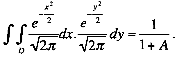
- a spatial filter (x, y) performing an optimal decoupling (corresponding to a minimum coupling coefficient ⁇ ) in the monomode fiber corresponds to a filter whose support for the phase binary function (with phase shift ⁇ equal to ⁇ ), D, check the following integral relation (minimizing the difference ⁇ - ⁇ on which the coupling coefficient ⁇ depends):
- FIG. 3a illustrating a filter profile as described in the patent application WO 02/071133 has an active part support profile of the filter, infinite in a transverse plane (that is to say not bounded to screw of the incident beam, according to the two dimensions of a transverse plane). Also, it has the disadvantage of not being optimized, especially in the presence of positioning defects of an incident beam. This point is particularly critical in the case of use in the form of a bar or a matrix of filters.
- the filters 102 or the filters of the 1-dimensional array 112 are odd quartile normal-law type defined according to one of the following relationships: or where q represents the quantile. In the case, for example, of the first or the third quartile, it represents the limit (coordinate in x) of the active part of the filter.
- FIGS. 3b to 3d show different embodiments of the filter 102 or of filters in a strip 112, these filters being inverse (that is to say of binary phase 0 or ⁇ ) and verifying one of the relationships (4) or (5).
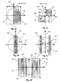
- FIG. 3b corresponds to a quartile satisfying the third quartile relation (5) with a central part 320 of the filter which is axially symmetrical along the axis 300 and has a width L1 close to 3.0352 ⁇ m along an axis 301 perpendicular to the axis 300.
- An incident optical beam symbolized by its imprint 322 has a section of radius R substantially equal to 4.5 ⁇ m and is centered on the intersection of the axes 300 and 301, the section being in a transverse plane. defined by the axes 300 and 301.
- the filter of FIG. 3a known per se, of order 1/2 (filter median) checks relation (3) but is not bounded in at least one direction and therefore can not verify relations (4) or (5).
- Two-dimensional bounded supports are also possible according to the invention, which is particularly particularly interesting for the realization of filter matrices.
- L2 is close to 2 ⁇ m and represents the distance separating the two parts 330 and 331 sidewalls of width L3 (close to 0.867 ⁇ m) of the filter illustrated in FIG. 3c which is axially symmetrical along the axis 300.
- an incident optical beam has a section of radius R substantially equal to 4.5 ⁇ m and is centered on the intersection of axes 300 and 301, the section being in a transverse plane defined by the axes 300 and 301.
- each boundary is defined by one of its two quantile. It is therefore necessary that the quantile differences associated with two separate bands do not overlap.
- q2n + 1 is such that the support remains bounded in at least one dimension vis-à-vis the incident optical beam.
- Figure 3d illustrates a filter based on a one-dimensional quantile combination, corresponding to three sums of quantile differences:
- Each term of the sum corresponds to two symmetrical bands per relative to the axis 300 (direction in which the filter is not bounded): three pairs of symmetrical bands respectively (340; 343), (341; 344) and (342; 345) correspond respectively to the differences (q2-q1), (q4-q3) and (q6-q5).
- the different bands are bounded vis-à-vis the incident beam.
- the collar of the beam 322 completely covers the bands 340 and 343 along the axis 301 and partly the bands 341 and 344.
- the bands 342 and 345 that are outside the footprint 322 are also useful since energy is present outside the neck of the Gaussian beam.
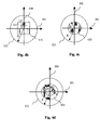
- FIGS. 4b to 4d show different embodiments of the filter 102 or of filters in a bar 112 satisfying these conditions (whereas the filter of FIG. 4a, known per se, obtained by combining two orthogonal medians satisfies the relation (2) has point symmetry but is not bounded).
- the filter 410 of FIG. 4b is two-dimensional, complies with the above conditions (bounded support, point symmetry and relation (2) verified) and, furthermore, is axially symmetrical along two orthogonal axes 300 and 301. , thus forming a square of side L5 close to 1.032 ⁇ m, which corresponds to the smallest modulated square pattern filter for an incident optical beam having a section of radius R substantially equal to 4.5 ⁇ m and centered on the intersection of the axes 300 and 301.
- the relation (2) checked by the filter 410 becomes: q3 is then the quantile of order normal law 1 2 + 1 2 2 or order 1 2 - 1 2 2 .
- the filter 420 of FIG. 4c is in the form of a disk of radius R1 close to log2 2 microns (log2 representing the natural logarithm of 2) which corresponds to the smallest disk for an incident optical beam having a section of radius R substantially equal to 4.5 ⁇ m and centered on the intersection of the axes of symmetry 300 and 301.
- the filter 420 satisfies the relation (2) corresponding to a quantile of normal law over two dimensions with active zone support bounded with respect to the incident beam (reference taken at the neck of the beam).
- FIG. 4d shows a filter 430 with a flexible pattern in the form of a ring of outer radius R3 close to 2.48 ⁇ m and an inner radius R2 of the order of 1.1 ⁇ m adapted to filter an incident optical beam having a section of radius.
- R substantially equal to 4.5 ⁇ m and centered on the intersection of the axes of symmetry 300 and 301.
- the filters illustrated with reference to FIGS. 3b, 3c and 4b to 4d are defined for a binary phase jump ⁇ between 0 and ⁇ .
- the stiffness of the phase jump is reduced and / or more complex phase profiles are set artwork. They have the advantage of loosening the technological constraint of stiffness of the filter or the phase jump.
- the coupling coefficient is first calculated as a function of the phase profile, of a maximum phase and a tested medium. In order to achieve maximum attenuation, try to cancel the coupling coefficient and we can choose the phase maximum and the corresponding optimum support.
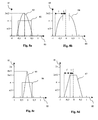
- Figures 8a to 8d illustrate this principle in two simple cases (parabolic or triangular phase profile) which also have a technological interest because they constitute a good approximation of real cases.
- a parabolic phase profile (in particular of the micro-lens type) corresponds, for example, to a transverse field effect in the case of a electro-optical spatial modulator or even a parabolic deformation of the membrane of a DMD as described in the article entitled "Monolithic piezoelectric mirror for wavefront correction "(or” piezoelectric mirror monolithic for wavefront correction "in French) written by J. Feinleib, S. Lipson, P. Cone and published in Applied Physics Letters, Vol. 25 pages 311 to 313 in 1974.
- FIG. 8a illustrates the principle of the adaptation of the value of the quartile in the case of a binary 82 or parabolic phase 83 profile.
- Figure 8b illustrates a bitwise combination of binary and parabolic profiles, where l is the half parabolic support and L is the half binary support.
- a triangular phase profile (in particular of the micro-prism type) for example, an engraving defect (shading effect) or deformation of a mirror by a micro-actuator as described in the article of Feinleib cited above.
- variable parameter is the slope of the prism.
- FIG. 8c illustrates the variation of the quartile as a function of phase modulation of the isosceles triangle type (biprism).
- the smallest phase-out canceling ⁇ is close to 8 ⁇ / 5. Note that the medium is smaller than the equivalent binary filter.
- a bitwise combination of binary and triangular profiles according to Figure 8d is also considered; this case corresponds to the trapezoidal profiles which constitute a good modeling of the effects of engraving and deformation of the membrane of a micro-mirror.
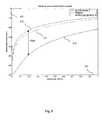
- the odd-numbered quartiles of normal law have the advantage for filters 102 or strips 112 of filters as presented opposite device of Figures 2a and 2b , a better tolerance to positioning errors. This is because the dynamic is optimal when the area of the spot covering the pixel is half of the total area, the positioning of the spot on the pixel is a very important step because the distribution of energy follows a Gaussian law .
- the filter corresponding to the third quartile is the least sensitive to positioning relative to the spot.
- the attenuation difference between the 512 curves (case median) and 510 (odd quartile) is of the order of 25 dB.
- This quartile filter odd also has many other advantages from the point of view of its technological implementation.
- the positioning parameter is more critical, for example, than focusing error in the case of the use of single-mode fiber such as detailed in the article by V. Nourrit, J.L. de Bougrenet de la Tocnaye and P. Chanclou, entitled “Propagation and diffraction of truncated Gaussian beam” (or “Propagation and diffraction of a truncated Gaussian beam” in French) in JOSA-A, Vol.18, pp. 546 to 554.2001.
- the odd-quartile filter is therefore particularly well adapted to realization of a DCE.
- a filter has a particular advantage, it is the third quartile as illustrated in Figure 3b .
- the wavelengths are demultiplexed spatially according to FIG. 2a or separated according to Figure 2b , and when the channels or spectral bands are well established (case of the blocker or DCE), it is necessary to optimize the interval between each of these filters with respect to the bandwidth per channel.
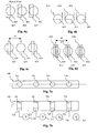
- FIGS. 6c and 6d show a bar 112 with filters 623 to 625 of type respectively third quartile or combination of quantiles, in a configuration optimizing the size (respectively d 1 and d 2) of the interval between two active zones (ie the zone with phase variation or delay).
- the filter 102 is therefore the simplest to achieve technologically and is particularly well suited to an implantation in the form of a bar 112 (it optimizes the bandwidth). It is also the binary filter that allows the most large inter-pixel area. We will see now the interest of the latter property.
- Each mirror or deformable membrane is separated by one or more activation devices (actuator) or cantilever. These areas are unavoidable and are real dead zones for the modulator especially in matrix form.
- actuator activation devices
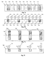
- Figures 7a and 7b respectively illustrate a top view and a sectional view of a bar 700 of filters 701 to 704 according to the invention in a two-dimensional profile as shown with reference to Figure 4c.
- the filters 701 to 704 are of any type according to the invention as illustrated in particular with reference to FIGS. 3b, 3c and 4b to 4d.
- Well-adapted filters 701 to 704 may in particular be of any geometry (for example with radial symmetry for a DMD) or implanted in one or two-dimensional form using, for example, phase shift means of the MEMS or DMD type.
- the filters 701 to 704 are associated with electrodes driving them by applying a corresponding voltage 710 to 713.
- the modulator illustrated with reference to FIGS. 7c in plan view and 7d in section comprises pixels 721 to 724 and 730 to 735 juxtaposed and regularly distributed.
- the use of the third quartile in this configuration amounts to activating one pixel in three (pixels 721 to 724 activated by applying a voltage V via the respective control means 741 to 744 and pixels 730 to 735 deactivated by application of a voltage zero via the respective control means 750 to 755).
- a second configuration illustrated with reference to FIGS. 7e (top view) and 7f (section) consists in arranging the modulating zone comprising filters 761 to 764 only in the central zone.
- the 3rd quartile filters 761-64 which optimizes the active area relative dead zone makes it easier this technological operation. Given the size of the gap, this zone can thus be used to electrically pass the active areas using voltage source 770 to 773.
- the passivation is optical.
- the third quartile is the simplest binary filter (in resolution and drawing) to implement and which offers the largest inter-pixel interval, thus facilitating both inter-pixel and 1a passivation operations. limitation of transverse field effects.
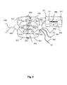
- the principle of the odd quartile binary filter of normal law can be applied to the case of a guided structure with rectangular mode weakly multi-mode.
- the filter is made differently and by means of an electro-optical element. In this case, the application of the field does not take place in parallel with the optical axis, but perpendicular to it.
- Filters 920 and 925 are similar.
- the filter 921 comprises an active zone 940 connecting the phasars 921 and 931.
- the modulating zone is directly etched in the guide and the phase shift is obtained by applying an electric field perpendicular to the guide. The value of this phase shift is determined, in particular, by the length of the active zone L.
- the guided structure is therefore well suited to the implementation of the third quartile because it guarantees binary phase shifts.
- the AWG configuration is equivalent to an assembly called 4f in free space, as illustrated in Figure 1b, with Fourier plane in the center of mounting.
- the skilled person can bring any variant into the definition of the filters verifying the conditions specified above, and in particular of odd quartiles and quantile support quantile combination.
- filters is not limited to a function attenuation but extends to any system with a single mode fiber output, particular equalizer, attenuators, switches, mode converters, ...
- the implementation of the invention is not limited to filters whose Modular patterns are in one plane but also extends to filters whose support patterns bounded on at least one dimension (in relation to the incident beam) are in separate planes: thus, for example, both parts 330 and 331 of the filter illustrated with reference to Figure 3 are not necessarily in the same plane but can be placed respectively in planes offset from the direction of propagation of the incident beam. More generally, a programmable filter pattern can be placed in several perpendicular to the axis of propagation of the incident beam, the sum of the footprints (or global impression) of the modular patterns respecting the support conditions bounded with respect to the incident beam on at least one direction and corresponding to a combination of quantiles.
Abstract
Description
La présente invention se rapporte au domaine des atténuateurs optiques notamment variables sous forme individuelle, de barrettes ou de matrices dans la perspective, entre autres, de la réalisation de bloqueurs sélecteurs variables de longueurs d'onde pour réseaux optiques WDM.The present invention relates to the field of optical attenuators particular variables in individual form, of bars or dies in the perspective, among others, the realization of variable selector blockers of wavelengths for optical WDM networks.
La particularité de ce type de fonction est de requérir des atténuations importantes (généralement supérieures à 35dB) et d'opérer sur des bandes passantes de largeurs typiques comprises entre 50GHz et 100GHz. Différentes techniques sont utilisées pour atteindre cet objectif.The peculiarity of this type of function is to require attenuations (usually greater than 35dB) and operate on passers of typical widths between 50GHz and 100GHz. different techniques are used to achieve this goal.
L'une d'entre elles consiste à générer, au moyen d'un filtre spatial, des perturbations du faisceau optique avant son injection dans une fibre monomode, de façon à exciter les modes d'ordres supérieurs, qui seront ainsi rapidement atténués. Compte tenu qu'il est souhaitable d'optimiser les pertes d'insertion, on a recours de préférence aux filtres de phase pure (généralement binaires pour des raisons de simplicité de réalisation).One of them consists in generating, by means of a spatial filter, disturbances of the optical beam before it is injected into a single-mode fiber, so as to excite the higher order modes, which will be quickly mitigated. Since it is desirable to optimize insertion losses, we have preference for pure phase filters (usually binary for reasons of simplicity of realization).
Cette idée a été notamment divulguée dans les articles «Excitation and scattering of modes on a dielectric or optical fibre» (ou "excitation et diffusion de modes sur un diélectrique ou une fibre optique" en français) , de Snyder (publié dans le magazine IEEE Trans. on Microwave Theory Vol. MIT 17, N°12, 1969) et «Transfer function of long spliced graded index fibers with mode scramblers» (ou "Fonction de transfert de longues fibres à index gradué avec brouilleurs de mode" en français), de M. Ikeda and K. Kitayama, (publié dans la revue Applied Optics, Vol. 17, pp. 63-67 en 1978). Ces articles décrivent des techniques basées sur l'introduction d'un élément absorbant, diffusant ou diffractant dans un guide pour exciter des modes supérieurs. Néanmoins, ces techniques de l'art antérieur présentent l'inconvénient de ne pas permettre une adaptation des paramètres par programmation.This idea was notably disclosed in the articles "Excitation and scattering of modes on a dielectric or optical fiber "(or" excitation and diffusion of modes on a dielectric or optical fiber "in French), from Snyder (published in the magazine IEEE Trans. on Microwave Theory Vol. MIT 17, No. 12, 1969) and "Transfer function of long spliced index finger fibers with scramblers mode" (or "Long Fiber Graduated Index Transfer Function with Mode Jammers" in French), by M. Ikeda and K. Kitayama, (published in the journal Applied Optics, Flight. 17, pp. 63-67 in 1978). These articles describe techniques based on the introduction of an absorbing, diffusing or diffracting element into a guide for to excite higher modes. Nevertheless, these techniques of the prior art have the disadvantage of not allowing an adaptation of the parameters by programming.
La demande de brevet internationale WO 02/071133 de la société Xtellus (marque déposée) présente un atténuateur pour fibre optique selon différents modes de réalisation relativement simple à mettre en oeuvre. Selon une technique illustrée dans cette demande de brevet, un faisceau optique incident traverse une zone à cristal liquide commandé électriquement. Les électrodes sont mises en oeuvre de sorte à définir des pixels dans une section transversale de cette zone. Ainsi, selon un premier mode de réalisation illustré en regard de la figure 3a, le profil à une dimension d'une section marquée par un axe horizontal 301 et un axe vertical 300 divisant respectivement la section en deux parties de largeurs égales L comprend deux pixels 310 et 311, le pixel 310 étant piloté par des électrodes. La largeur L est supérieure au rayon R du faisceau incident (représenté par son col dans le cas d'un faisceau gaussien), symbolisé par son empreinte 302. Ainsi, en appliquant une tension prédéterminée à ces dernières, il est possible de commander le pixel 310 pour le déphaser vis-à-vis du pixel 311 avec un déphasage :
- nul, le signal incident n'étant, alors, pas atténué ; ou
- égal à π, le signal incident étant transformé dans un mode élevé empêchant le signal de pénétrer dans une fibre à simple mode et entraínant ainsi une atténuation variable en fonction de la tension appliquée.
- no, the incident signal being, then, not attenuated; or
- equal to π, the incident signal being converted into a high mode preventing the signal from entering a fiber single mode and thus causing a variable attenuation depending on the applied voltage.
En résumé, la commande appliquée aux électrodes permet de transformer ou non le signal incident dans un mode élevé ne pouvant se propager dans une fibre de sortie et donc de l'atténuer ou non.In summary, the command applied to the electrodes makes it possible to transform or not the incident signal in a high mode can not propagate in a output fiber and therefore attenuate it or not.
Selon une variante de réalisation présentée dans la demande de brevet
WO 02/071133, le profil d'une section est à deux dimensions définissant quatre
zones carrées 400 à 403 de longueurs L égales et séparées par les axes 300 et 301.
Chacune des zones 400 à 403 peut être pilotée par des électrodes distinctes. According to an alternative embodiment presented in the patent application WO 02/071133, the profile of a section is two-dimensional defining four
Cette technique de l'art antérieur présente l'inconvénient de ne pas être optimisée pour le couplage aux modes d'ordres supérieurs. En outre, sa mise en oeuvre n'est pas non plus optimisée, en particulier pour des modes de réalisation adaptés à filtrer plusieurs longueurs d'ondes indépendamment.This technique of the prior art has the drawback of not being optimized for coupling to higher order modes. In addition, its implementation The work is not optimized either, especially for adapted to filter several wavelengths independently.
L'une des variantes de réalisation présente une meilleure tolérance aux erreurs de positionnement en présence d'un défaut de positionnement par rapport à un faisceau incident. Néanmoins, cette variante n'est pas optimisée du point de vue du coefficient de couplage (perte de dynamique d'atténuation).One of the variants of embodiment has a better tolerance to positioning errors in the presence of a relative positioning defect to an incident beam. Nevertheless, this variant is not optimized from the point of view of view of the coupling coefficient (loss of attenuation dynamics).
L'invention selon ses différents aspects a notamment pour objectif de pallier ces inconvénients de l'art antérieur.The invention in its various aspects is intended in particular to overcome these disadvantages of the prior art.
Plus précisément, un objectif de l'invention est de prévoir des filtres optiques optimaux pour le découplage dans une fibre optique monomode.More specifically, an object of the invention is to provide filters optically optimal for decoupling in a monomode optical fiber.
Un autre objectif de l'invention est de permettre des filtres relativement simples à mettre en oeuvre, notamment sous forme de barrettes ou de matrices, permettant, en particulier de réduire leur taille.Another object of the invention is to enable relatively simple to implement, especially in the form of bars or dies, allowing, in particular to reduce their size.
Encore un autre objectif de l'invention est de garantir une bonne tolérance au positionnement et donc de faciliter l'agencement optique.Yet another object of the invention is to guarantee a good tolerance positioning and therefore facilitate the optical arrangement.
Un objectif de l'invention est également de permettre une implantation de filtres optiques pouvant être basée sur des technologies diverses.An object of the invention is also to allow an implementation of optical filters that can be based on various technologies.
Dans ce but, l'invention propose un filtre spatial de phase apte à recevoir un faisceau optique incident pour le transmettre vers une fibre de sortie monomode, le filtre étant adapté à être positionné sensiblement perpendiculairement à la direction de propagation du faisceau et comprenant un profil de phase spatialement variable et étant adapté à exciter les modes évanescents de la fibre de sortie. Le filtre est remarquable en ce que son profil présente :
- un motif modulable avec une distribution de phase correspondant sensiblement à une combinaison d'au moins un quantile de loi normale sur au moins une dimension ;et
- un support de zone déphasante borné vis-à-vis du faisceau incident suivant la ou les dimensions.
- a modulable pattern with a phase distribution substantially corresponding to a combination of at least one normal-law quantile over at least one dimension, and
- a phase-shifted zone support bounded to the incident beam according to the one or more dimensions.
En outre, le motif modulable suit une distribution de phase correspondant
sensiblement à une combinaison d'au moins un quantile de loi normale sur cette
ou ces dimensions. Ainsi, dans le cas d'une amplitude du signal A constante sur
un support D (dans un plan (x,y)) et pouvant varier de 1 (en l'absence
d'atténuation) à 0 (si l'atténuation est totale), la distribution de phase
correspondant à un quantile de loi normale suit la relation suivante :
Selon une caractéristique particulière, le filtre spatial est remarquable en ce que le profil présente un motif modulable avec une distribution de phase correspondant sensiblement à un quartile d'ordre impair de loi normale sur une dimension perpendiculaire à la direction de propagation du faisceau incident.According to a particular characteristic, the spatial filter is remarkable in that the profile has a flexible pattern with a phase distribution substantially corresponding to a quartile of odd order of normal law on a dimension perpendicular to the direction of propagation of the incident beam.
Ainsi, le support de zone déphasante est borné :
- sur une dimension : l'empreinte du faisceau incident (ou de son col dans le cas d'un faisceau gaussien) couvre complètement le motif modulable suivant cette dimension ; ou
- sur deux dimensions : l'empreinte du faisceau incident (ou de son col dans le cas d'un faisceau gaussien) couvre complètement le motif modulable suivant les deux dimensions d'un plan perpendiculaire (plan transverse) à la direction de propagation du faisceau.
- on one dimension: the imprint of the incident beam (or its neck in the case of a Gaussian beam) completely covers the modular pattern according to this dimension; or
- on two dimensions: the imprint of the incident beam (or its neck in the case of a Gaussian beam) completely covers the motive modulable along the two dimensions of a plane perpendicular (transverse plane) to the direction of propagation of the beam.
Un quartile impair de loi normale est défini selon l'une des relations
suivantes :

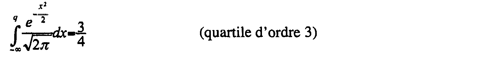
Selon une caractéristique particulière, le filtre spatial est remarquable en ce que sa distribution de phase correspond sensiblement au troisième quartile de loi normale sur la dimension.According to a particular characteristic, the spatial filter is remarkable in that that its phase distribution corresponds substantially to the third quartile of law normal on the dimension.
Ces filtres à une dimension sont optimaux pour le découplage dans une fibre optique monomode. Parmi ces filtres, les quartiles impairs (notamment le troisième quartile) présentent des avantages décisifs du point de vue de la prise en compte de leur implantation technologique. Ils permettent notamment de réduire la taille de la zone active par rapport au col du faisceau gaussien.These one-dimensional filters are optimal for decoupling in a single-mode optical fiber. Among these filters, the odd quartiles (especially the third quartile) have decisive advantages from the point of view of taking into account of their technological implantation. In particular, they make it possible to reduce the size of the active area relative to the Gaussian beam neck.
Cette propriété est particulièrement intéressante lorsqu'on associe plusieurs filtres sous la forme de barrettes ou de matrices requises, notamment pour la réalisation de DCE (« Dynamic Channel Equalizer » ou « Egaliseur de canal dynamique ») ou de ROADM (« Reconfigurable Optical Add & Drop Multiplexer » ou « Multiplexeur à insertion-extraction optique reconfigurable ») puisque l'utilisation de quartile d'ordre 3 permet d'optimiser la zone entre chaque zone déphasante ou retardante sans perte de résolution ni contrainte supplémentaire de bande passante.This property is particularly interesting when combining several filters in the form of bars or matrices required, in particular for the realization of DCE ("Dynamic Channel Equalizer" or "Equalizer of dynamic channel ") or ROADM (" Reconfigurable Optical Add & Drop Multiplexer "or" Reconfigurable optical insertion-extraction multiplexer ") since the use of quartile of order 3 makes it possible to optimize the zone between each dephasing or retarding zone without loss of resolution or constraint additional bandwidth.
L'utilisation de quartile d'ordre 3 est également particulièrement intéressante lorsque les moyens de déphasage comprennent des éléments de modulation électro-optiques (anisotropes (par exemple de type cristal liquide) ou isotropes (par exemple de type nano-PDLC), car elle permet d'optimiser l'aire de la zone active par rapport à l'aire du spot (correspondant au faisceau optique incident, la référence étant prise à l'aire couverte par le col du faisceau). Cela permet notamment de limiter les effets de champs transverses dus aux pixels voisins.The use of 3rd order quartile is also particularly interesting when the phase shift means comprise elements of electro-optical modulation (anisotropic (for example of the liquid crystal type) or isotropic (for example of the nano-PDLC type), because it makes it possible to optimize the the active area relative to the area of the spot (corresponding to the optical beam incident, the reference being made to the area covered by the neck of the beam). it in particular to limit the effects of transverse fields due to pixels neighbors.
En outre, l'utilisation du troisième quartile dans un système comprenant plusieurs filtres permet une passivation optique plus facile de la zone intermédiaire (comprenant, par exemple, une résine photosensible, du verre, du silicium ou tout autre élément susceptible d'être gravé et présentant un retard fixe par rapport à une zone centrale du système modulable (notamment grâce à un élément électro-optique ou électromécanique)). Ainsi, on obtient des transitions de phase plus raides qu'au moyen d'une barrette (SLM) continûment modulable.In addition, the use of the third quartile in a system comprising multiple filters allows easier optical passivation of the area intermediate (including, for example, a photoresist, glass, silicon or any other element likely to be etched and having a fixed delay relative to a central zone of the modular system (notably thanks to a electro-optical or electromechanical element)). Thus, we obtain transitions steeper than by means of a continuously modulable strip (SLM).
De plus, l'utilisation du troisième quartile permet une isolation électrique plus facile de la zone intermédiaire séparant deux zones actives correspondant à deux filtres et ainsi une réduction des effets de champs transverses dans le cas ou le matériau déphasant est électro-optique.In addition, the use of the third quartile allows electrical insulation easier of the intermediate zone separating two active zones corresponding to two filters and thus a reduction of transverse field effects in the case where the phase-shifting material is electro-optical.
On note que le matériau séparant deux filtres distincts peut être à la fois un isolant électrique et un passivant optique.Note that the material separating two distinct filters can be both a electrical insulation and an optical passivator.
Selon une caractéristique particulière, le filtre spatial est remarquable en ce que la combinaison est une somme d'au moins une différence de deux quantiles de loi normale sur une dimension perpendiculaire à la direction de propagation du faisceau incident, la somme étant égale à 1/4 ou 3/4.According to a particular characteristic, the spatial filter is remarkable in that that the combination is a sum of at least one difference of two quantiles of normal law on a dimension perpendicular to the direction of propagation of the incident beam, the sum being 1/4 or 3/4.
On optimise ainsi le filtre.This optimizes the filter.
Selon une caractéristique particulière, le filtre spatial est remarquable en ce qu'il est à symétrie axiale.According to a particular characteristic, the spatial filter is remarkable in that that it is axially symmetrical.
Ainsi, on obtient une meilleure tolérance aux défauts de positionnement du filtre vis-à-vis du faisceau incident.Thus, a better tolerance to the positioning defects of the filter vis-à-vis the incident beam.
Selon une caractéristique particulière, le filtre spatial est remarquable en ce que le profil présente :
- un motif modulable avec une distribution de phase correspondant sensiblement à une combinaison d'au moins un quantile de loi normale sur les deux dimensions d'un plan transverse vis-à-vis du faisceau incident ;et
- un support de zone active borné vis-à-vis du faisceau incident suivant les deux dimensions.
- a modulable pattern with a phase distribution substantially corresponding to a combination of at least one normal-law quantile on both dimensions of a transverse plane with respect to the incident beam, and
- an active zone support bounded with respect to the incident beam in both dimensions.
Ainsi, on obtient des filtres particulièrement intéressants à mettre en oeuvre sous forme de matrice de plusieurs filtres.Thus, we obtain particularly interesting filters to implement as a matrix of several filters.
Selon une caractéristique particulière, le filtre spatial est remarquable en ce que la combinaison appartient au groupe comprenant :
- un quantile de loi normale ; et
- une différence de deux quantiles distincts de loi normale.
- a quantile of normal law; and
- a difference of two distinct quantiles of normal law.
Selon une caractéristique particulière, le filtre spatial est remarquable en ce qu'il est à symétrie ponctuelle.According to a particular characteristic, the spatial filter is remarkable in that it is point symmetrical.
Ainsi, on obtient également une meilleure tolérance aux défauts de positionnement du filtre vis-à-vis du faisceau incident.Thus, a better tolerance to defects in positioning of the filter vis-à-vis the incident beam.
Dans le cas de mise en oeuvre sous forme de matrice de filtres élémentaires, la taille de la matrice est optimisée lorsque les filtres élémentaires sont carrés ou en forme de disque (espace entre filtres élémentaires réduit).In the case of implementation in the form of filter matrix elementary, the size of the matrix is optimized when the elementary filters are square or disk-shaped (space between elementary filters reduced).
Selon une caractéristique particulière, le filtre spatial est remarquable en ce qu'une première partie du profil est carrée ou rectangulaire sur la ou les dimensions.According to a particular characteristic, the spatial filter is remarkable in that that a first part of the profile is square or rectangular on the dimensions.
Un filtre à profil carré ou rectangulaire sur au moins une partie (par exemple binaire ou à plus de deux valeurs) est relativement simple à mettre en oeuvre si les moyens de déphasage sont adaptés (cas notamment de moyens de déphasage électro-optiques).A square or rectangular profile filter on at least one part (for binary example or more than two values) is relatively simple to implement if the phase-shifting means are suitable (in particular electro-optical phase shift).
Selon une caractéristique particulière, le filtre spatial est remarquable en ce que le déphasage sur la première partie du profil est égal à π.According to a particular characteristic, the spatial filter is remarkable in that that the phase shift on the first part of the profile is equal to π.
Ainsi, les modes évanescents de la fibre de sortie sont excités lorsque le filtre est activé permettant ainsi d'atténuer ou de bloquer le faisceau optique.Thus, the evanescent modes of the output fiber are excited when the filter is activated, thereby attenuating or blocking the optical beam.
Selon une caractéristique particulière, le filtre spatial est remarquable en ce qu'une deuxième partie du profil est parabolique sur la ou les dimensions.According to a particular characteristic, the spatial filter is remarkable in that that a second part of the profile is parabolic on the dimension (s).
Le profil est ainsi complètement parabolique ou en partie parabolique (une autre partie pouvant alors être notamment linéaire).The profile is thus completely parabolic or partly parabolic (a another part can then be particularly linear).
Le filtre à profil parabolique est particulièrement bien adapté à un filtre à moyens de déphasage basés sur l'utilisation de miroirs électromécaniques à membrane dont la déformation est elle-même parabolique.The parabolic profile filter is particularly well adapted to a filter with phase shift means based on the use of electromechanical mirrors to membrane whose deformation is itself parabolic.
Selon une caractéristique particulière, le filtre spatial est remarquable en ce qu'une troisième partie du profil est triangulaire sur la ou les dimensions.According to a particular characteristic, the spatial filter is remarkable in that that a third part of the profile is triangular on the dimension or dimensions.
Le profil est ainsi complètement triangulaire ou en partie triangulaire (une autre partie pouvant alors être notamment parabolique ou rectangulaire). The profile is thus completely triangular or partly triangular (a another part can then be parabolic or rectangular).
Afin de minimiser la dimension de la zone active du filtre à profil respectivement parabolique et triangulaire, le déphasage maximal correspondant sera préférentiellement choisi sensiblement égal à respectivement à 3π/2 et 8π/5.To minimize the size of the active area of the profile filter respectively parabolic and triangular, the corresponding maximum phase shift will preferably be chosen substantially equal to respectively 3π / 2 and 8π / 5.
Selon une caractéristique particulière, le filtre spatial est remarquable en ce qu'il comprend des moyens de commande de l'atténuation variable sur une partie du profil.According to a particular characteristic, the spatial filter is remarkable in that that it includes control means of variable attenuation on a part profile.
Selon une caractéristique particulière, le filtre spatial est remarquable en ce que les moyens comprennent au moins un élément de modulation électro-optique ou électro-mécanique commandable.According to a particular characteristic, the spatial filter is remarkable in that that the means comprise at least one electro-optical modulation element or electro-mechanical controllable.
L'invention concerne également un système apte à recevoir au moins un faisceau optique et comprenant au moins un filtre tel que décrit précédemment et plus précisément un filtre spatial de phase apte à recevoir un faisceau optique incident pour le transmettre vers une fibre de sortie monomode, le filtre étant adapté à être positionné sensiblement perpendiculairement à la direction de propagation du faisceau et comprenant un profil de phase spatialement variable et étant adapté à exciter les modes évanescents de la fibre de sortie., le profil du filtre présentant :
- un motif modulable avec une distribution de phase correspondant sensiblement à une combinaison d'au moins un quantile de loi normale sur au moins une dimension ;et
- un support de zone déphasante borné vis-à-vis du faisceau incident suivant la ou les dimensions.
- a modulable pattern with a phase distribution substantially corresponding to a combination of at least one normal-law quantile over at least one dimension, and
- a phase-shifted zone support bounded to the incident beam according to the one or more dimensions.
Selon une caractéristique particulière, le système est remarquable en ce qu'il comprend au moins deux des filtres.According to a particular characteristic, the system is remarkable in that it includes at least two of the filters.
Ainsi, les filtres optimisant à la fois le couplage aux modes d'ordres supérieurs et l'implantation technologique, sont particulièrement bien adaptés à une mise en oeuvre, par exemple, sous la forme de barrettes ou de matrices de plusieurs filtres.Thus, the filters optimizing both the coupling to the order modes and technological implantation, are particularly well adapted to an implementation, for example, in the form of bars or matrices of several filters.
Selon une caractéristique particulière, le système est remarquable en ce que chacun des filtres comprend une zone modulante commandée électriquement. According to a particular characteristic, the system is remarkable in that each of the filters comprises an electrically controlled modulating zone.
Ainsi, le système peut être mis en oeuvre sous la forme d'un composant particulièrement compact.Thus, the system can be implemented in the form of a component particularly compact.
Selon une caractéristique particulière, le système est remarquable en ce qu'il comprend des moyens d'imagerie, au moins un des filtres étant positionné dans un plan d'imagerie des moyens d'imagerie.According to a particular characteristic, the system is remarkable in that it comprises imaging means, at least one of the filters being positioned in an imaging plan imaging means.
Le système ainsi formé avec, par exemple, des lentilles ou des moyens équivalents peut comprendre plusieurs plans d'imagerie. Des éléments optiques adaptés à réaliser une fonction propre au système (notamment multiplexage en longueur d'onde, démultiplexage, amplification,...) peuvent être avantageusement introduits dans les plans focaux des lentilles des moyens d'imagerie.The system thus formed with, for example, lenses or means equivalents may include multiple imaging plans. Optical elements adapted to perform a function specific to the system (in particular multiplexing in wavelength, demultiplexing, amplification, ...) can be advantageously introduced into the focal planes of the lenses of the imaging means.
Selon une caractéristique particulière, le système est remarquable en ce qu'il comprend des moyens de démultiplexage en longueur d'onde du ou des faisceaux optiques pour former des faisceaux optiques démultiplexés destinés à être filtrés par les filtres.According to a particular characteristic, the system is remarkable in that it includes means for demultiplexing the wavelength (s) of the optical beams to form demultiplexed optical beams for to be filtered by the filters.
Un tel système peut être réalisé à base de moyens de multiplexage/démultiplexage par exemple de type prisme associé à des fibres ou des moyens d'imagerie ou encore de type phasars suivant le principe d'un AWG (de l'anglais « Arrayed Wave Guide » ou « Réseaux de Guides d'ondes »).Such a system can be achieved by means of multiplexing / demultiplexing, for example of the prism type associated with fibers or imaging means or phasars according to the principle of an AWG (English "Arrayed Wave Guide" or "Waveguide Networks").
Selon une caractéristique particulière, le système est remarquable en ce qu'il comprend des moyens de blocage sélectif d'au moins certaines longueurs d'onde du ou des faisceaux optiques.According to a particular characteristic, the system is remarkable in that it includes selective locking means of at least some lengths wave or optical beams.
Selon une caractéristique particulière, le système est remarquable en ce qu'il comprend des moyens de routage du faisceau optique.According to a particular characteristic, the system is remarkable in that it includes means for routing the optical beam.
Ainsi, les systèmes de filtres selon l'invention sont appropriés à l'implantation de fonctions de routage spatial et en longueur d'onde notamment du type DCE et ROADM.Thus, the filter systems according to the invention are suitable for the implementation of spatial and wavelength routing functions in particular DCE and ROADM type.
L'invention concerne en outre un procédé de calcul d'un filtre tel que décrit précédemment, le procédé comprenant :
- une étape de détermination d'un coefficient de couplage du filtre en fonction d'un profil de phase, d'un maximum de phase et d'un support du filtre ;
- une étape de minimisation du coefficient de couplage ; et
- une étape de détermination du support correspondant sensiblement à un coefficient de couplage minimal.
- a step of determining a coupling coefficient of the filter as a function of a phase profile, a maximum of phase and a support of the filter;
- a step of minimizing the coupling coefficient; and
- a step of determining the support substantially corresponding to a minimum coupling coefficient.
Ainsi, il est possible de réaliser des filtres optimisés pour, exemple, que la distribution de phase corresponde sensiblement à un quartile impair de loi normale pour une dimension ou à une combinaison de quantiles de loi normale pour deux dimensions.Thus, it is possible to achieve optimized filters for, for example, that the phase distribution corresponds substantially to an odd quartile of law normal for a dimension or a combination of normal law quantiles for two dimensions.
Les avantages du système et du procédé sont les mêmes que ceux du filtre, ils ne sont pas détaillés plus amplement.The advantages of the system and the process are the same as those of the filter, they are not detailed further.
D'autres caractéristiques et avantages de l'invention apparaítront plus clairement à la lecture de la description suivante d'un mode de réalisation préférentiel, donné à titre de simple exemple illustratif et non limitatif, et des dessins annexés, parmi lesquels :
- les figures 1a à 1d présentent un synoptique de système de filtrage optique conforme à l'invention selon différents modes particuliers de réalisation ;
- les figures 2a et 2b illustrent des systèmes de filtrage comprenant une barrette de filtres optiques tels que décrits en regard de la figure 1a;
- les figures 3a , 4a, 6a et 6b illustrent des filtres connus en soi ;
- les figures 3b à 3d présentent des filtres à quantiles à une dimension mis en oeuvre dans les systèmes des figures 1a à 1d selon des variantes de réalisation de l'invention ;
- les figures 4b à 4d illustrent des filtres à quantiles à deux dimensions mis en oeuvre dans les systèmes des figures 1a à 1d selon des variantes de réalisation de l'invention ;
- la figure 5 représente des courbes de tolérance sur la position du pixel dans les systèmes des figures 1a à 1d ;
- les figures 6a à 6d décrivent schématiquement la taille et la position d'un spot de lumière par rapport aux pixels dans les filtres des figures 1a à 1d ;
- les figures 7a à 7f illustrent une passivation de filtres présentés en regard des figures 1a à 1d ;
- les figures 8a à 8d présentent des profils paraboliques radiaux ou trapézoïdaux de filtres à une dimension tels qu'illustrés dans les figures 1a à 1d ; et
- la figure 9 décrit une structure d'un égaliseur à base d'AWG mettant en oeuvre des filtres selon l'invention.
- FIGS. 1a to 1d present a block diagram of an optical filtering system according to the invention according to various particular embodiments;
- FIGS. 2a and 2b illustrate filtering systems comprising an array of optical filters as described with reference to FIG. 1a;
- Figures 3a, 4a, 6a and 6b illustrate filters known per se;
- FIGS. 3b to 3d show one-dimensional quantile filters implemented in the systems of FIGS. 1a to 1d according to alternative embodiments of the invention;
- FIGS. 4b to 4d illustrate two-dimensional quantile filters implemented in the systems of FIGS. 1a to 1d according to alternative embodiments of the invention;
- FIG. 5 represents tolerance curves on the position of the pixel in the systems of FIGS. 1a to 1d;
- Figures 6a to 6d schematically describe the size and position of a light spot relative to the pixels in the filters of Figures 1a to 1d;
- FIGS. 7a to 7f illustrate passivation of filters presented with reference to FIGS. 1a to 1d;
- Figures 8a-8d show radial or trapezoidal parabolic profiles of one-dimensional filters as illustrated in Figures 1a-1d; and
- FIG. 9 describes a structure of an AWG-based equalizer implementing filters according to the invention.
Le principe général de l'invention repose sur une catégorie de filtres permettant un découplage optimal de l'énergie injectée dans une fibre optique monomode.The general principle of the invention is based on a category of filters enabling optimal decoupling of the energy injected into an optical fiber singlemode.
Parmi ces filtres, une catégorie de filtres à symétrie axiale ou ponctuelle présente l'avantage d'offrir une meilleure tolérance d'alignement et dont certains, que l'on détaillera, sont plus faciles à implanter et bien adaptés à la réalisation de DCE et de ROADM.Among these filters, a class of filters with axial or point symmetry has the advantage of offering better alignment tolerance and some of which, which will be detailed, are easier to implement and well adapted to the achievement of DCE and ROADM.
Pour la réalisation de barrettes ou de matrice de filtres, on sélectionne préférentiellement un type de filtre qui présente en outre l'avantage d'optimiser l'espace inter pixel bien approprié à l'implantation sous forme de modulateur spatiaux de lumière (SLM) dans le contexte de la réalisation d'un DCE. Différentes réalisations techniques sont possibles en fonction de choix technologiques associés aux moyens d'atténuation optique (électro-optiques ou électro-mécaniques) ou aux moyens de transmission du faisceau lumineux (fibres accolées aux filtres, moyens de focalisation, multiplexeurs ou démultiplexeur, moyens de routages, d'amplification, ...).For the realization of bars or matrix of filters, one selects preferentially a type of filter which has the further advantage of optimizing the inter pixel space well suited to the implantation in the form of a modulator light (SLM) in the context of achieving a DCE. Different technical achievements are possible according to choice associated with optical attenuation means (electro-optical or electromechanical equipment) or to the means of transmitting the light beam (fibers attached to the filters, focusing means, multiplexers or demultiplexer, means of routing, amplification, ...).
Les filtres sont considérés comme minces et n'introduisent préférentiellement aucune déformation du faisceau gaussien autres que le déphasage (notamment pas de courbure de champ, pas d'élargissement du col). Filters are considered thin and do not introduce preferentially no deformation of the Gaussian beam other than the phase shift (in particular no curvature of the field, no enlargement of the neck).
Les figures 1a à 1d présentent différents modes de réalisation selon l'invention. Figures 1a to 1d show different embodiments of the invention.
Plus précisément, la figure 1a illustre un filtre 102 ou modulateur spatial
de lumière, selon l'invention, placé entre deux fibres optiques monomodes 101 et
103 permettant respectivement la propagation d'un faisceau incident 100 et d'un
faisceau de sortie 104. Selon l'invention, la zone active du filtre 102 est à support
borné dans au moins une dimension, c'est-à-dire que la largeur du motif
modulable correspondant est de taille strictement inférieure à celle d'un faisceau
optique incident représenté par son col dans le cas d'un faisceau gaussien. Les
fibres 101 et 103 sont accolées au filtre 102. Une ou plusieurs tensions de
commande du filtre 102 permettent de déphaser plus ou moins fortement le
faisceau incident 100 pour obtenir le faisceau de sortie 104, l'atténuation variable
apparaissant lors du couplage du faisceau de sortie.More precisely, FIG. 1a illustrates a
La figure 1b présente un DCE possédant une architecture similaire à celle du système de la figure 1a, le filtre 102 étant remplacé par une barrette de filtres 112, selon l'invention, et comportant, en outre, des systèmes d'imagerie avec multiplexeur ou démultiplexeur. Selon l'invention, la zone active de chaque filtre de la barrette 112 est à support borné dans au moins la dimension selon laquelle on réplique le motif, c'est-à-dire que le motif modulable correspondant a une largeur (prise dans la dimension où on réplique le motif) strictement inférieure à celle d'un faisceau optique incident représenté par son col dans le cas d'un faisceau gaussien. Plus précisément, le DCE comprend successivement :
une fibre d'entrée 101 véhiculant un faisceau optique 110 ;- un premier système d'imagerie adapté à créer une image démultiplexée spatialement du faisceau optique 110 (en fonction de ses longueurs d'ondes) sur le filtre 102 ;
- la barrette de filtres 112 ;
- un second système d'imagerie adapté à créer une image multiplexée à
l'entrée d'une
fibre de sortie 103 à partir de l'image du faisceau traversant la barrette de filtres 112 ; et - la
fibre de sortie 103véhiculant un faisceau 111 égalisé par la barrette de filtres 112 en fonction des longueurs d'ondes du faisceauincident 110.
- an
input fiber 101 conveying anoptical beam 110; - a first imaging system adapted to create a spatially demultiplexed image of the optical beam 110 (depending on its wavelengths) on the
filter 102; - the
filter bar 112; - a second imaging system adapted to create a multiplexed image at the input of an
output fiber 103 from the image of the beam passing through thefilter bar 112; and - the
output fiber 103 conveying abeam 111 equalized by thefilter array 112 as a function of the wavelengths of theincident beam 110.
Selon une variante de l'invention, des moyens de collimation sont placés
entre la fibre d'entrée 101 et le premier système d'imagerie et entre le second
système d'imagerie et la fibre de sortie 103. Ces moyens de collimation sont
préférentiellement accolés aux fibres respectivement d'entrée 101 et de sortie 103.According to a variant of the invention, collimation means are placed
between the
Le premier système d'imagerie comprend successivement:
une lentille 113 de distance focale f1 située à la distance f1 de la sortie de lafibre 101 ;- un démultiplexeur 118 (par exemple un prisme) adapté à démultiplexer spatialement le faisceau incident en fonction de sa ou de ses longueurs d'onde, et situé à la distance f1 de la lentille 113, le faisceau incident étant donc imagé sur le démultiplexeur 118 ;
une lentille 114 de distance focale f2 située à la distance f2 du démultiplexeur 118 et de la barrette de filtres 112, le faisceau démultiplexé étant donc imagé (avec ses composantes spectrales séparées spatialement) sur labarrette 112.
- a
lens 113 of focal length f1 located at the distance f1 of the output of thefiber 101; - a demultiplexer 118 (for example a prism) adapted to spatially demultiplex the incident beam according to its wavelength (s), and situated at the distance f1 from the
lens 113, the incident beam thus being imaged on thedemultiplexer 118; - a
lens 114 of focal length f2 located at the distance f2 of thedemultiplexer 118 and thefilter array 112, the demultiplexed beam being thus imaged (with its spatially separated spectral components) on thestrip 112.
Le second système d'imagerie comprend successivement:
une lentille 115 de distance focale f3 située à la distance f3 de la barrette 112 ;- un multiplexeur 119 (par exemple un prisme) adapté à multiplexer le
faisceau incident égalisé par
la barrette 112 en fonction de ses composantes spectrales, et situé à la distance f3 de la cette dernière ; une lentille 116 de distance focale f4 située à la distance f4 du multiplexeur 119 et de lafibre de sortie 103, le faisceau multiplexé et égalisé étant donc imagé sur lafibre de sortie 103.
- a
lens 115 of focal length f3 located at the distance f3 of thebar 112; - a multiplexer 119 (for example a prism) adapted to multiplex the incident beam equalized by the
strip 112 as a function of its spectral components, and situated at the distance f3 from the latter; - a
lens 116 of focal length f4 located at the distance f4 from themultiplexer 119 and theoutput fiber 103, the multiplexed and equalized beam being thus imaged on theoutput fiber 103.
Selon des variantes de réalisation du système illustré en regard de la figure
1b, des éléments optiques adaptés à réaliser une fonction propre au système
(notamment un élément démultiplexeur de longueur d'onde) sont introduits dans
les plans focaux des lentilles des systèmes d'imagerie (en remplacement ou en sus
de multiplexeurs/démultiplexeurs 118 et 119).According to alternative embodiments of the system illustrated with reference to FIG.
1b, optical elements adapted to perform a function specific to the system
(including a wavelength demultiplexer element) are introduced in
the focal planes of the lenses of the imaging systems (in replacement or in addition
multiplexer /
Les figures 1c et 1d représentent des mises en oeuvre avec miroir des systèmes illustrés respectivement en regard des figures 1a et 1b. Les éléments communs portent les mêmes références et ne sont pas décrits davantage. Figures 1c and 1d show mirror implementations of the systems illustrated respectively with reference to Figures 1a and 1b. The common elements have the same references and are not described further.
Selon la figure 1c, le système comprend un filtre 102 ou modulateur
spatial de lumière, selon l'invention, placé entre une fibre optique 101 monomode
et un miroir 120 accolé au filtre 102, la fibre 101 permettant respectivement la
propagation d'un faisceau incident 100 et d'un faisceau de sortie 104 obtenu après
filtrage sur le filtre 102 et réflexion sur le miroir 120.According to FIG. 1c, the system comprises a
Selon la figure 1d, l'égaliseur optique comprend successivement la fibre
d'entrée/sortie 111 monomode, le premier système d'imagerie, la barrette de
filtres 112 et un miroir 130 accolé à la barrette 112. Ainsi, la fibre 111, véhicule le
faisceau incident 100 et le faisceau de sortie 104 obtenu après filtrage d'une image
démultiplexée spatialement sur la barrette 112 et réflexion sur le miroir 130.According to FIG. 1d, the optical equalizer successively comprises the single-mode input /
La figure 2a illustre le principe de fonctionnement des systèmes présentés
en regard des figures 1b et 1d (les moyens de collimations n'étant pas
représentés). Le faisceau incident possédant n composantes spectrales de
longueurs d'ondes respectives λ1 à λn est démultiplexé spatialement et une image
démultiplexée spatialement est produite sur la barrette 112, comme indiqué
schématiquement sur la figure 2a. La barrette 112 comprend n filtres 211 à 21n
commandables (préférentiellement électriquement) de manière indépendante.
Ainsi, la barrette 112 permet d'atténuer voire de bloquer les composantes
spectrales du faisceau incident. FIG. 2a illustrates the operating principle of the systems presented with reference to FIGS. 1b and 1d (the collimation means not being shown). The incident beam having n spectral components of respective wavelengths λ1 to λ n is spatially demultiplexed and a spatially demultiplexed image is produced on the
La figure 2b illustre un système mettant en oeuvre la barrette 112 de filtres
211 à 21n et n fibres d'entrée 201 à 20n, associées respectivement à n fibres de
sortie 221 à 22n. Selon cette variante de réalisation de l'invention, chacun des
filtres 211 à 21n est inséré entre une fibre d'entrée respectivement 201 à 20n et
une fibre de sortie 221 à 22n. Ainsi, le système de la figure 2b permet d'atténuer
ou de bloquer indépendamment n faisceaux d'entrée 241 à 24n pour produire n
faisceaux de sortie 251 à 25n. FIG. 2b illustrates a system implementing the
Des fondements théoriques permettant d'optimiser les profils d'atténuations des filtres selon l'invention sont présentés ci-après.Theoretical foundations for optimizing profiles attenuations of the filters according to the invention are presented below.
Le mode d'une fibre monomode est approché par le profil gaussien
suivant :
- ω0 représente le col à l'origine (soit le rayon du faisceau gaussien pris à mi-hauteur de la distribution d'énergie du faisceau ; et
- x et y représentent les coordonnées spatiales (par rapport à une origine placée au centre de la fibre) selon deux axes perpendiculaires dans une section transversale de la fibre.
- ω 0 represents the neck at the origin (ie the radius of the Gaussian beam taken at mid-height of the energy distribution of the beam, and
- x and y represent the spatial coordinates (with respect to an origin placed at the center of the fiber) along two perpendicular axes in a cross section of the fiber.
Si le déphasage Δϕ est binaire, le coefficient de couplage η s'exprime sous la forme : η = α + βcosΔϕ où α et β sont deux coefficients positifs dépendant du support du filtre. Pour minimiser le coefficient de couplage, Δϕ doit donc être égal à π.If the phase shift Δφ is binary, the coupling coefficient η is expressed under the form: η = α + βcosΔφ where α and β are two dependent positive coefficients of the filter support. To minimize the coupling coefficient, Δφ must therefore be equal to π.
Un filtre spatial (x,y) réalisant un découplage optimal (correspondant à un
coefficient de couplage η minimal) dans la fibre monomode correspond à un filtre
dont le support de la fonction binaire de phase (avec déphasage Δϕ égal à π), D,
vérifie la relation intégrale suivante (minimisant la différence α - β dont dépend
le coefficient de couplage η) :

Dans le cas d'une amplitude du signal A constante sur le support D et
pouvant varier de 1 (en l'absence d'atténuation) à 0 (si l'atténuation est totale), la
relation (1) est généralisable de la façon suivante :
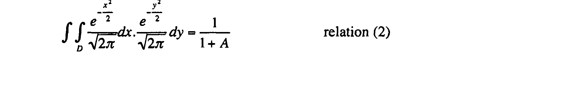
La notion d'atténuation résiduelle a un intérêt dans le cas d'un composant électro-optique, par exemple, où le déphasage peut s'accompagner d'une absorption ou d'une diffusion résiduelle.The notion of residual attenuation is of interest in the case of a component electro-optical, for example, where the phase shift can be accompanied by a absorption or residual diffusion.
Parmi les filtres spatiaux vérifiant les relations (1) ou (2), on s'intéresse notamment, pour des raisons liées à leurs avantages pratiques, aux filtres présentant une symétrie axiale (cas à une dimension) ou ponctuelle (cas à deux dimensions) et à support borné sur la partie active du filtre (partie modulante).Among the spatial filters checking relations (1) or (2), we are interested in in particular, for reasons related to their practical advantages, to filters with axial symmetry (one-dimensional case) or one-off (two-sided case) dimensions) and with bounded support on the active part of the filter (modulating part).
Dans le cas où l'on peut considérer une dimension comme quasi infinie
(soit très grande en pratique devant les autres dimensions), ce qui correspond, en
particulier, au cas de la réalisation de filtres sous forme de barrette (par exemple la
barrette 112 illustrée en regard des figures 1b, 1d, 2a et 2b), le critère selon la
relation (1) devient (Dx représentant le support de la partie active du filtre suivant
la direction x en supposant que le support D est infini suivant la direction y) :

La figure 3a illustrant un profil de filtre tel que décrit dans la demande de brevet WO 02/071133 possède un profil à support de partie active du filtre, infini dans un plan transverse (c'est-à-dire non borné vis-à-vis du faisceau incident, selon les deux dimensions d'un plan transverse). Aussi, il présente l'inconvénient de ne pas être optimisé, notamment en présence de défauts de positionnement d'un faisceau incident. Ce point est particulièrement critique dans le cas de l'utilisation sous forme d'une barrette ou d'une matrice de filtres. FIG. 3a illustrating a filter profile as described in the patent application WO 02/071133 has an active part support profile of the filter, infinite in a transverse plane (that is to say not bounded to screw of the incident beam, according to the two dimensions of a transverse plane). Also, it has the disadvantage of not being optimized, especially in the presence of positioning defects of an incident beam. This point is particularly critical in the case of use in the form of a bar or a matrix of filters.
Selon l'invention, les filtres 102 ou les filtres de la barrette 112 de
dimension 1 sont de type quartiles impairs de loi normale définis selon l'une des
relations suivantes :

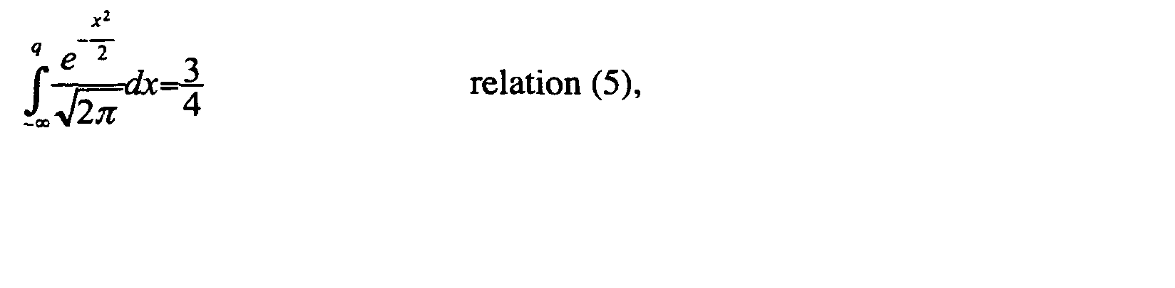
Les caractéristiques mathématiques des quartiles impairs de loi normale
sont présentés à la page 201 du livre "Calcul des probabilités" de A. Rényi édité
chez Dunod en 1966 (dans le chapitre IV paragraphe 13 intitulé « Médiane et
Quantiles »).The mathematical characteristics of odd quartiles of normal law
are presented on
Les figures 3b à 3d présentent différents modes de réalisation du filtre 102
ou de filtres dans une barrette 112, ces filtres étant inverses (c'est-à-dire de phase
binaire 0 ou π) et vérifiant l'une des relations (4) ou (5). FIGS. 3b to 3d show different embodiments of the
Plus précisément, la figure 3b correspond à un quartile vérifiant la relation
(5) de troisième quartile avec une partie centrale 320 du filtre qui est à symétrie
axiale suivant l'axe 300 et possède une largeur L1 voisine de 3,0352 µm suivant
un axe 301 perpendiculaire à l'axe 300. Un faisceau optique incident symbolisé
par son empreinte 322 possède une section de rayon R sensiblement égal à 4,5 µm
et est centré sur l'intersection des axes 300 et 301, la section étant dans un plan
transverse défini par les axes 300 et 301.More precisely, FIG. 3b corresponds to a quartile satisfying the third quartile relation (5) with a
En revanche, le filtre de la figure 3a, connu en soi, d'ordre 1/2 (filtre
médian) vérifie la relation (3) mais n'est pas à support borné dans au moins une
direction et ne peut donc pas vérifier les relations (4) ou (5).On the other hand, the filter of FIG. 3a, known per se, of
Des supports bornés à deux dimensions sont aussi envisageables selon l'invention, ce qui est, notamment, particulièrement intéressant pour la réalisation de matrices de filtres.Two-dimensional bounded supports are also possible according to the invention, which is particularly particularly interesting for the realization of filter matrices.
Ainsi, des filtres à symétrie ponctuelle par rapport à support borné vérifie les relations (1) ou (2).Thus, filters with point symmetry compared to bounded support verifies relationships (1) or (2).
La figure 3c correspond à une combinaison de deux filtres quantiles non
connexes et plus exactement à une différence de quantiles égale à 1/4 et vérifiant
la relation :

L2 est voisin de 2 µm et représente la distance séparant les deux parties
latérales 330 et 331 de largeur L3 (proche de 0,867 µm) du filtre illustré en figure
3c qui est à symétrie axiale suivant l'axe 300.L2 is close to 2 μm and represents the distance separating the two
Comme précédemment, un faisceau optique incident possède une section
de rayon R sensiblement égal à 4,5 µm et est centré sur l'intersection des axes 300
et 301, la section étant dans un plan transverse défini par les axes 300 et 301.As before, an incident optical beam has a section
of radius R substantially equal to 4.5 μm and is centered on the intersection of
D'autres combinaisons de quantiles peuvent être mise en oeuvre selon l'invention, notamment les combinaisons de quantiles composées d'une somme de différences de quantiles. Dans le cas à une dimension chaque différence de quantile correspond à deux zones actives associées respectivement à deux bandes symétriques.Other combinations of quantiles can be implemented according to the invention, in particular combinations of quantiles composed of a sum of quantile differences. In the case of one dimension each difference of quantile is two active areas associated respectively with two bands symmetrical.
Pour chaque bande, chaque frontière est définie par un de ses deux quantiles. Il est donc nécessaire que les différences de quantiles associés à deux bandes distinctes ne se chevauchent pas.For each band, each boundary is defined by one of its two quantile. It is therefore necessary that the quantile differences associated with two separate bands do not overlap.
Ainsi, une combinaison de (2n+2) quantiles de loi normale dans le cas
général à une dimension s'écrit suivant la relation :

Lorsque n vaut 0, on a une simple différence de quantiles de loi normale. Si en outre, q1 vaut 0, le deuxième terme de la différence vaut 1/2 et on se ramène au cas du troisième quartile à une dimension. Lorsque q1 vaut -∞, le deuxième terme de la différence vaut 0 et on obtient le premier quartile à une dimension.When n is 0, we have a simple quantile difference of normal law. If in addition, q1 is 0, the second term of the difference is equal to 1/2 and we come back to in the case of the third-quartile quartile. When q1 is -∞, the second The term of the difference is 0 and we obtain the first quartile at one dimension.
On note que, selon l'invention, q2n+1 est tel que le support reste borné dans au moins une dimension vis-à-vis du faisceau optique incident.It is noted that, according to the invention, q2n + 1 is such that the support remains bounded in at least one dimension vis-à-vis the incident optical beam.
La figure 3d illustre un filtre basé sur une combinaison de quantiles à une
dimension, correspondant à trois sommes de différences de quantiles :

Chaque terme de la somme correspond à deux bandes symétriques par
rapport à l'axe 300 (direction suivant laquelle le filtre n'est pas borné) : trois
paires de bandes symétriques respectivement (340;343), (341;344) et (342;345)
correspondent respectivement aux différences (q2-q1), (q4-q3) et (q6-q5). Suivant
l'axe 301, les différentes bandes sont bornées vis-à-vis du faisceau incident. Dans
le cas d'un faisceau gaussien, selon l'exemple de la figure 3d, le col du faisceau
322 couvre totalement les bandes 340 et 343 suivant l'axe 301 et en partie les
bandes 341 et 344. Les bandes 342 et 345 qui sont en dehors de l'empreinte 322
sont également utiles puisque de l'énergie est présente en dehors du col du
faisceau gaussien.Each term of the sum corresponds to two symmetrical bands per
relative to the axis 300 (direction in which the filter is not bounded): three
pairs of symmetrical bands respectively (340; 343), (341; 344) and (342; 345)
correspond respectively to the differences (q2-q1), (q4-q3) and (q6-q5). next
the
Les figures 4b à 4d présentent différents modes de réalisation du filtre 102
ou de filtres dans une barrette 112 vérifiant ces conditions (alors que le filtre de la
figure 4a, connu en soi, obtenu par combinaison de deux médians orthogonaux
vérifie la relation (2) est à symétrie ponctuelle mais n'est pas à support borné). FIGS. 4b to 4d show different embodiments of the
Cette notion de support borné est importante en pratique car une troncature du faisceau dans une dimension dans ce cas ne peut être compensée suivant l'autre dimension qui est infinie.This notion of bounded support is important in practice because truncation of the beam in one dimension in this case can not be compensated according to the other dimension that is infinite.
Dans une configuration de filtre à deux dimensions (sur un support borné), on considère généralement une représentation cartésienne ou radiale permettant de simplifier les calculs en les rapprochant du cas à une dimension.In a two-dimensional filter configuration (on a bounded support), we generally consider a Cartesian or radial representation allowing simplify the calculations by bringing them closer to the one-dimensional case.
Plus précisément, le filtre 410 de la figure 4b est à deux dimensions,
respecte les conditions ci-dessus (support borné, symétrie ponctuelle et relation
(2) vérifiée) et, en outre, est à symétrie axiale suivant deux axes 300 et 301
orthogonaux, formant ainsi un carré de coté L5 proche de 1,032 µm, qui
correspond au plus petit filtre à motif modulable carré pour un faisceau optique
incident possédant une section de rayon R sensiblement égal à 4,5 µm et centré
sur l'intersection des axes 300 et 301. Dans ce cas, la relation (2) vérifiée par le
filtre 410 devient:

Le filtre 420 de la figure 4c a la forme d'un disque de rayon R1 proche de
Selon l'invention, une combinaison de quantiles correspondant à un filtre à une dimension est applicable également au cas à deux dimensions. Deux cas particuliers à deux dimensions peuvent être modélisés simplement avec des combinaisons:
- le cas à symétrie de révolution (cas du disque, de la couronne ou d'une
succession de couronnes) (l'intégrale se calcule alors en coordonnées
polaires) selon la relation :
avec qi < qj et q'i < q'j si i < j ;

et - le cas du carré ou du rectangle (où on peut séparer l'intégrale double
en deux intégrales simples correspondants au cas à une dimension) :
avec qi < qj et q'i < q'j si i < j ;
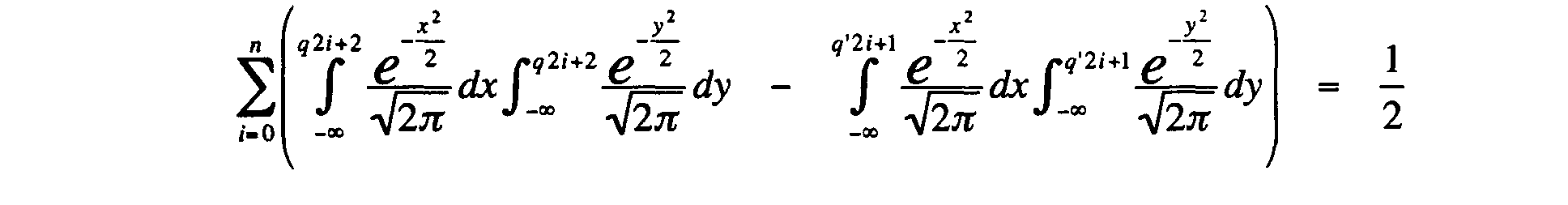
- the case with symmetry of revolution (case of the disk, the crown or a succession of crowns) (the integral is then calculated in polar coordinates) according to the relation: with qi < qj and q ' i < q ' j if i <j;
and - the case of the square or the rectangle (where we can separate the double integral into two simple integrals corresponding to the one-dimensional case): with qi <qj and q'i <q'j if i <j ;
La figure 4d présente un filtre 430 à motif modulable en forme de
couronne de rayon extérieur R3 proche de 2,48 µm et de rayon intérieur R2 de
l'ordre de 1,1 µm adapté à filtrer un faisceau optique incident possédant une
section de rayon R sensiblement égal à 4,5 µm et centré sur l'intersection des axes
de symétrie 300 et 301. Le filtre 430 satisfait à la relation (2) et plus précisément
correspond à une différence de quantiles radiaux à support borné respectivement
D1 (de rayon R3) et D2 (de rayon R2) :
Les filtres illustrés en regards des figures 3b, 3c et 4b à 4d sont définis pour un saut de phase binaire Δϕ compris entre 0 et π. Selon des variantes de l'invention, afin de satisfaire certaines contraintes technologiques, la raideur du saut de phase est réduite et/ou des profils de phase plus complexes sont mis en oeuvre. Ils présentent l'avantage de relâcher la contrainte technologique de la raideur du filtre ou du saut de phase.The filters illustrated with reference to FIGS. 3b, 3c and 4b to 4d are defined for a binary phase jump Δφ between 0 and π. According to variants of the invention, in order to satisfy certain technological constraints, the stiffness of the phase jump is reduced and / or more complex phase profiles are set artwork. They have the advantage of loosening the technological constraint of stiffness of the filter or the phase jump.
Dans le cas à une dimension, le principe du quartile selon les relations (4) et (5) reste valable et seule la valeur de la phase est modifiée.In the one-dimensional case, the quartile principle according to relations (4) and (5) remains valid and only the value of the phase is changed.
Plus généralement, dans le cas de filtre à une ou deux dimensions à profil de phase variable quelconque, pour déterminer la géométrie du support optimal, on calcule d'abord le coefficient de couplage en fonction du profil de phase, d'une phase maximale et d'un support testé. Afin d'obtenir l'atténuation maximale, on cherche à annuler le coefficient de couplage et on peut ainsi choisir la phase maximale et le support optimal correspondant.More generally, in the case of a filter with one or two dimensions with profile any variable phase, to determine the optimal support geometry, the coupling coefficient is first calculated as a function of the phase profile, of a maximum phase and a tested medium. In order to achieve maximum attenuation, try to cancel the coupling coefficient and we can choose the phase maximum and the corresponding optimum support.
Afin d'optimiser le filtre, on applique, selon l'invention, le procédé de suivant :
- on détermine d'abord un coefficient de couplage η du filtre en fonction d'un profil de phase, d'un maximum de phase et d'un support du filtre ; puis
- on minimise ensuite le coefficient de couplage ; et
- on détermine le support correspondant sensiblement à un coefficient de couplage minimal.
- a coupling coefficient η of the filter is first determined as a function of a phase profile, a phase maximum and a filter support; then
- the coupling coefficient is then minimized; and
- the medium is determined corresponding substantially to a minimum coupling coefficient.
Les figures 8a à 8d illustrent ce principe dans deux cas simples (profil de phase parabolique ou triangulaire) qui présentent en outre un intérêt technologique car ils constituent une bonne approximation de cas réels. Figures 8a to 8d illustrate this principle in two simple cases (parabolic or triangular phase profile) which also have a technological interest because they constitute a good approximation of real cases.
Un profil de phase parabolique (notamment de type micro-lentille)
correspond, par exemple, à un effet de champ transverse dans le cas d'un
modulateur spatial électro-optique ou bien encore une déformation parabolique de
la membrane d'un DMD tel que décrit dans l'article intitulé « Monolithic
piezoelectric mirror for wavefront correction » (ou "miroir piezoélectrique
monolithique pour une correction de front d'onde"en français) écrit par J.
Feinleib, S. Lipson, P. Cone et paru dans Applied Physics Letters, Vol. 25, pages
311 à 313 en 1974.A parabolic phase profile (in particular of the micro-lens type)
corresponds, for example, to a transverse field effect in the case of a
electro-optical spatial modulator or even a parabolic deformation of
the membrane of a DMD as described in the article entitled "Monolithic
piezoelectric mirror for wavefront correction "(or" piezoelectric mirror
monolithic for wavefront correction "in French) written by J.
Feinleib, S. Lipson, P. Cone and published in Applied Physics Letters, Vol. 25
Dans ce cas, la phase optimale n'est plus π et on peut obtenir une
expression analytique de la valeur du quartile et du déphasage Δϕ nécessaire en
calculant le coefficient de couplage η qui peut s'écrire sous la forme :
La valeur du coefficient B, (B>0) dépend du dimensionnement du
modulateur et peut être ramenée à 1, en résolvant l'équation suivante:
La relation (10) s'écrit alors :
A partir de cette relation, on optimise le filtre en déterminant le support correspondant sensiblement à un coefficient de couplage minimal.From this relation, we optimize the filter by determining the support corresponding substantially to a minimum coupling coefficient.
La figure 8a illustre le principe de l'adaptation de la valeur du quartile
dans le cas d'un profil binaire 82 ou parabolique de phase 83. FIG. 8a illustrates the principle of the adaptation of the value of the quartile in the case of a binary 82 or
La figure 8b illustre une combinaison par morceaux de profils binaires et paraboliques , où l est le demi support parabolique et L le demi support binaire. La phase optimale varie alors en fonction du rapport L/l entre π (l = 0) et 3π/2 (L=0). Le plus petit support est obtenu pour l égal à 0 (cas binaire correspondant au profil 82). Figure 8b illustrates a bitwise combination of binary and parabolic profiles, where l is the half parabolic support and L is the half binary support. The optimal phase then varies according to the ratio L / l between π (l = 0) and 3π / 2 (L = 0). The smallest support is obtained for l equal to 0 (binary case corresponding to profile 82).
Un profil de phase triangulaire (notamment de type micro-prisme) correspond, par exemple, à un défaut de gravure (effet d'ombrage) ou à une déformation d'un miroir par un micro-actuateur tel que décrit dans l'article de Feinleib cité plus haut.A triangular phase profile (in particular of the micro-prism type) for example, an engraving defect (shading effect) or deformation of a mirror by a micro-actuator as described in the article of Feinleib cited above.
Un effet de champ transverse peut également être grossièrement modélisé par ce cas. Le paramètre variable est la pente du prisme.A transverse field effect can also be roughly modeled by this case. The variable parameter is the slope of the prism.
La figure 8c illustre la variation du quartile en fonction d'une modulation de phase du type triangle isocèle (biprisme). Dans ce cas, il existe un quartile optimisant le découplage et l'on montre que le plus petit déphasage annulant η est voisin de 8π/5. On note que le support est plus petit que le filtre binaire équivalent. FIG. 8c illustrates the variation of the quartile as a function of phase modulation of the isosceles triangle type (biprism). In this case, there is a quartile optimizing the decoupling and it is shown that the smallest phase-out canceling η is close to 8π / 5. Note that the medium is smaller than the equivalent binary filter.
Une combinaison par morceaux de profils binaires et triangulaires selon la figure 8d est également considérée ; ce cas correspond aux profils trapézoïdaux qui constituent une bonne modélisation des effets de gravures et de déformation de la membrane d'un micro-miroir. La phase optimale varie alors en fonction du rapport L'/l' entre π (l' = 0) et 8π/5 (L'=0) (où l' est le demi support triangulaire et L' le demi support binaire). Le plus petit support est obtenu pour L' nul (correspondant à un bi-prisme).A bitwise combination of binary and triangular profiles according to Figure 8d is also considered; this case corresponds to the trapezoidal profiles which constitute a good modeling of the effects of engraving and deformation of the membrane of a micro-mirror. The optimal phase then varies according to the ratio L '/ l ' between π ( l = 0) and 8π / 5 ( L '= 0) (where the is the half triangular support and L' the half binary support). The smallest support is obtained for the null (corresponding to a bi-prism).
Comme indiqué plus haut, les quartiles impairs de loi normale présentent
l'avantage pour des filtres 102 ou des barrettes 112 de filtres tels que présentées
en regard dispositif des figures 2a et 2b, d'une meilleure tolérance aux erreurs de
positionnement. Ceci vient du fait que la dynamique est optimale lorsque l'aire du
spot couvrant le pixel est la moitié de l'aire totale, le positionnement du spot sur le
pixel est donc une étape très importante car la distribution d'énergie suit une loi
gaussienne.As indicated above, the odd-numbered quartiles of normal law have the advantage for
Ce point devient encore plus critique lorsqu'il s'agit d'aligner plusieurs spots sur une barrette de filtres comme requis dans le cas d'un DCE. La figure 5 illustre l'impact de cette perturbation (erreur de positionnement par rapport à au centre du filtre, donné suivant l'abscisse 501 et exprimé en micron), en particulier sur la dynamique d'atténuation donné suivant l'axe des ordonnées 500 et exprimée en dB :
- sur un filtre médian connu en soi et basé sur le profil illustré en regard de la figure 3a, selon la courbe 512 ;
- sur un quartile d'ordre 3 (quartile impair) correspondant au profil illustré en regard de la figure 3b, selon la courbe 510 ; et
- sur une combinaison de quartiles correspondant au profil illustré en figure 3c, selon la courbe 511.
- on a median filter known per se and based on the profile illustrated with reference to FIG. 3a, according to the
curve 512; - on a quartile of order 3 (odd quartile) corresponding to the profile illustrated with reference to FIG. 3b, according to the
curve 510; and - on a combination of quartiles corresponding to the profile illustrated in Figure 3c, according to the
curve 511.
Le filtre correspondant au troisième quartile est le moins sensible au positionnement par rapport au spot. Ainsi, pour une erreur de positionnement du spot égale à 0,2 µm, la différence d'atténuation entres les courbes 512 (cas médian) et 510 (quartile impaire) est de l'ordre de 25 dB. Ce filtre à quartile impair présente également de nombreux autres avantages du point de vue de son implantation technologique.The filter corresponding to the third quartile is the least sensitive to positioning relative to the spot. Thus, for a positioning error of the spot equal to 0.2 μm, the attenuation difference between the 512 curves (case median) and 510 (odd quartile) is of the order of 25 dB. This quartile filter odd also has many other advantages from the point of view of its technological implementation.
Le paramètre de positionnement est plus critique, par exemple, qu'une erreur de focalisation dans le cas de l'utilisation de fibre monomode tel que détaillé dans l'article de V. Nourrit, J.L. de Bougrenet de la Tocnaye et P. Chanclou, intitulé «Propagation and diffraction of truncated Gaussian beam » (ou « propagation et diffraction d'un faisceau gaussien tronqué » en français) paru dans JOSA-A, Vol.18, pp. 546-554,2001.The positioning parameter is more critical, for example, than focusing error in the case of the use of single-mode fiber such as detailed in the article by V. Nourrit, J.L. de Bougrenet de la Tocnaye and P. Chanclou, entitled "Propagation and diffraction of truncated Gaussian beam" (or "Propagation and diffraction of a truncated Gaussian beam" in French) in JOSA-A, Vol.18, pp. 546 to 554.2001.
Le filtre à quartile impair est donc particulièrement bien adapté à la réalisation d'un DCE.The odd-quartile filter is therefore particularly well adapted to realization of a DCE.
Parmi les filtres à quartiles impairs, un filtre présente un avantage particulier, il s'agit du troisième quartile tel qu'illustré en figure 3b. Dans le cas d'une configuration impliquant une juxtaposition de pixels agissant sur chaque longueur d'onde ou sur un groupe de longueurs d'onde, comme c'est le cas dans un système où les longueurs d'onde sont démultiplexées spatialement selon la figure 2a ou séparées selon la figure 2b, et lorsque les canaux ou bandes spectrales sont bien établies (cas du bloqueur ou DCE), il est nécessaire d'optimiser l'intervalle entre chacun de ces filtres au regard de la bande passante par canal.Among the odd-quartile filters, a filter has a particular advantage, it is the third quartile as illustrated in Figure 3b . In the case of a configuration involving a juxtaposition of pixels acting on each wavelength or group of wavelengths, as is the case in a system where the wavelengths are demultiplexed spatially according to FIG. 2a or separated according to Figure 2b , and when the channels or spectral bands are well established (case of the blocker or DCE), it is necessary to optimize the interval between each of these filters with respect to the bandwidth per channel.
Les figures 6c et 6d représentent une barrette 112 avec filtres 623 à 625 de
type respectivement troisième quartile ou combinaison de quantiles, dans une
configuration optimisant la taille (respectivement d1 et d2) de l'intervalle entre
deux zones actives (i.e. la zone à variation de phase ou de retard). FIGS. 6c and 6d show a
Si l'on veut obtenir le même résultat (dimension zone active / dimension du pixel total) avec le filtre médian de la figure 3a, il faut réduire la bande passante des 2/3 tel qu'illustré en regard des figures 6a et 6b selon deux configurations.If one wants to obtain the same result (dimension active area / dimension of the total pixel) with the median filter of FIG. 3a, it is necessary to reduce the bandwidth of 2/3 as illustrated with regard to FIGS. 6a and 6b according to FIG. two configurations.
Le filtre 102 est donc le plus simple à réaliser technologiquement et est
particulièrement bien adapté à une implantation sous forme de barrette 112 (il
optimise la bande passante). Il est en outre le filtre binaire qui autorise la plus
grande zone inter-pixel. On va voir maintenant l'intérêt de cette dernière
propriété.The
L'emploi d'un matériau, par exemple électro-optique, pour la modulation de phase ou électro-mécanique pour un retard variable des chemins optiques, peut introduire des contraintes supplémentaires sur le rapport entre la zone active et la dimension totale du pixel, liées au choix technologique des moyens de déphasage. Dans le cas d'une réalisation sous forme de barrette ou de matrice, il est très utile d'optimiser ce facteur de remplissage. On envisage ci-après deux types de moyens de déphasage :
- les moyens électro-mécaniques (par exemple micro-miroirs déformables de type MEMS, membrane déformable de type DMD ; et
- les modulateurs électro-optiques (notamment de type cristal liquide, nano-PDLC,...).
- electromechanical means (for example MEMS-type deformable micro-mirrors, deformable membrane of the DMD type, and
- electro-optical modulators (in particular of the liquid crystal type, nano-PDLC, etc.).
Chaque miroir ou membrane déformable est séparé par un ou plusieurs dispositifs d'activation (actuateur) ou de cantilever. Ces zones sont incontournables et sont de véritables zones mortes pour le modulateur en particulier sous forme matricielle. L'utilisation du troisième quartile selon un profil, par exemple à deux dimensions tel que décrit en regard des figures 4b et 4c, permet d'optimiser la zone morte, car ce quartile est le quartile binaire qui optimise le facteur de remplissage.Each mirror or deformable membrane is separated by one or more activation devices (actuator) or cantilever. These areas are unavoidable and are real dead zones for the modulator especially in matrix form. The use of the third quartile according to a profile, for example two-dimensional as described with reference to FIGS. 4b and 4c , makes it possible to optimize the dead zone, because this quartile is the binary quartile which optimizes the filling factor.
Les figures 7a et 7b illustrent respectivement une vue de dessus et une vue
en coupe d'une barrette 700 de filtres 701 à 704 conformes à l'invention selon un
profil à deux dimensions tel qu'illustré en regard de la figure 4c. Selon différentes
variantes de réalisation de l'invention, les filtres 701 à 704 sont d'un type
quelconque conforme à l'invention tel qu'illustré notamment en regard des figures
3b, 3c et 4b à 4d. Les filtres 701 à 704 bien adaptés peuvent notamment être de
géométrie quelconque (par exemple à symétrie radiale pour un DMD) ou
implantés sous forme à une ou deux dimensions mettant en oeuvre, par exemple,
des moyens de déphasage du type MEMS ou DMD. Les filtres 701 à 704 sont
associés à des électrodes les pilotant par application d'une tension correspondante
710 à 713. Figures 7a and 7b respectively illustrate a top view and a sectional view of a
Dans le cas d'un modulateur électro-optique (par exemple de type à cristal liquide ou à nano-PDLC commandé électriquement), deux configurations illustrées en regard des figures 7c à 7f sont possibles.In the case of an electro-optical modulator (for example of liquid crystal or electrically controlled nano-PDLC type), two configurations illustrated with reference to FIGS. 7c to 7f are possible.
Selon une première configuration, le modulateur illustré en regard des
figures 7c en vue de dessus et 7d en coupe comprend des pixels 721 à 724 et 730
à 735 juxtaposés et régulièrement répartis. L'emploi du troisième quartile dans
cette configuration revient à activer un pixel sur trois (pixels 721 à 724 activés par
application d'une tension V via les moyens de commande respectifs 741 à 744 et
pixels 730 à 735 désactivés par application d'une tension nulle via les moyens de
commande respectifs 750 à 755). On peut limiter ainsi l'interaction électrique
entre pixels voisins (effet de champ transverse plus ou moins sensible selon la
technologie utilisée). According to a first configuration, the modulator illustrated with reference to FIGS. 7c in plan view and 7d in section comprises
Une deuxième configuration illustrée en regard des figures 7e (vue de
dessus) et 7f (coupe) consiste à disposer la zone modulante comprenant des filtres
761 à 764 uniquement dans la zone centrale. L'utilisation du 3ème quartile pour les
filtres 761 à 64, qui optimise le rapport zone active zone morte rend plus facile
cette opération technologique. Compte tenu de la dimension de l'intervalle, cette
zone peut ainsi être utilisée pour passiver électriquement les zones actives à l'aide
de source de tension 770 à 773. Selon une variante, la passivation est optique.A second configuration illustrated with reference to FIGS. 7e (top view) and 7f (section) consists in arranging the modulating
Cela présente l'intérêt supplémentaire de permettre des transitions de phase plus nettes entre deux niveaux de phase que dans la configuration précédente et de limiter encore plus l'interaction électrique entre pixels, et par conséquent les effets de champ transverse.This has the added benefit of allowing transitions of phase sharper between two phase levels than in the configuration preceding and further limit the electrical interaction between pixels, and by therefore the transverse field effects.
Dans ces deux cas, le troisième quartile est le filtre binaire le plus simple (en résolution et dessin) à implanter et qui offre le plus grand intervalle inter-pixel, facilitant ainsi à la fois les opérations de passivation inter-pixel et 1a limitation des effets de champ transverse.In these two cases, the third quartile is the simplest binary filter (in resolution and drawing) to implement and which offers the largest inter-pixel interval, thus facilitating both inter-pixel and 1a passivation operations. limitation of transverse field effects.
Le principe du filtre binaire à quartile impair de loi normale peut être appliqué au cas d'une structure guidée à mode rectangulaire faiblement multi-mode. Le filtre est réalisé de manière différente et au moyen d'un élément électro-optique. Dans ce cas, l'application du champ ne s'effectue pas parallèlement à l'axe optique, mais perpendiculairement à celui-ci.The principle of the odd quartile binary filter of normal law can be applied to the case of a guided structure with rectangular mode weakly multi-mode. The filter is made differently and by means of an electro-optical element. In this case, the application of the field does not take place in parallel with the optical axis, but perpendicular to it.
La figure 9 illustre un AWG (de l'anglais « Arrayed Wave Guide » ou « Réseaux de Guides d'ondes ») qui comprend :
- un guide d'onde d'entrée 900 associé à une fibre d'entrée non représentée ;
- des phasars (lignes à retard sous forme de guides d'onde) 910 à 915
et 930 à 935 ; - une lentille 901 (ou « star coupler » en anglais) interfaçant la
fibre d'entrée 900 avec les phasars 910 à 915 ; - des filtres déphaseurs 920 à 925 reliant respectivement les phasars 910
à 915
aux phasars 930 à 935 ; - des guides d'onde de sortie 903 à 906 associés chacun à une longueur d'onde différente λi (i compris entre 1 et n) et destinés chacun à émettre un faisceau de sortie vers une fibre de sortie ; et
une lentille 902 reliant les phasars 930 à 935 aux guides 903 à 906.
- an
input waveguide 900 associated with a not shown input fiber; - phasars (delay lines in the form of waveguides) 910 to 915 and 930 to 935;
- a 901 lens (or "star coupler" in English) interfacing the
input fiber 900 with thephasars 910 to 915; - phase-shifting
filters 920 to 925 respectively connecting thephasars 910 to 915 to thephasars 930 to 935; -
output waveguides 903 to 906 each associated with a different wavelength λ i ( i between 1 and n ) and each intended to emit an output beam to an output fiber; and - a
lens 902 connecting thephasars 930 to 935 to theguides 903 to 906.
Les filtres 920 et 925 sont similaires. A titre illustratif, le filtre 921
comprend une zone active 940 reliant les phasars 921 et 931. Dans ce mode de
réalisation, la zone modulante est directement gravée dans le guide et le
déphasage est obtenu par application d'un champ électrique perpendiculairement
au guide. La valeur de ce déphasage est déterminée, notamment, par la longueur
de la zone active L. La structure guidée est donc bien adaptée à l'implantation du
troisième quartile car elle garantit des déphasages binaires.
La configuration AWG est équivalente à un montage dit 4f en espace libre, tel qu'illustré en regard de la figure 1b, avec plan de Fourier au centre du montage.The AWG configuration is equivalent to an assembly called 4f in free space, as illustrated in Figure 1b, with Fourier plane in the center of mounting.
L'intérêt principal de cette solution est de pouvoir réaliser par ce moyen un égaliseur ou sélecteur de bande spectrale en utilisant une configuration de démultiplexage du type AWG comme indiquée dans l'article de M.C. Parker, A.D. Cohen, R.J Mears, intitulé « Dynamic digital holographic wavelength filtering » (ou « filtrage dynamique, numérique et holographique de longueur d'ondes » holographique et paru dans JLT Vol. 16, No. 7, pp. 1259-1270, en 1998).The main interest of this solution is to be able to achieve by this means a equalizer or spectral band selector using a configuration of demultiplexing of the AWG type as stated in the article by M.C. Parker, A. D. Cohen, R. J. Mears, entitled "Dynamic digital holographic wavelength filtering "(or" dynamic, digital and holographic filtering of length "holographic" and appeared in JLT Vol. 16, No. 7, pp. 1259-1270, in 1998).
Bien entendu, l'invention n'est pas limitée aux exemples de réalisation mentionnés ci-dessus.Of course, the invention is not limited to the embodiments mentioned above.
En particulier, l'homme du métier pourra apporter toute variante dans la définition des filtres vérifiant les conditions précisées ci-avant, et notamment de quartiles impairs et de combinaison de quantiles à support borné.In particular, the skilled person can bring any variant into the definition of the filters verifying the conditions specified above, and in particular of odd quartiles and quantile support quantile combination.
On note que la mise en oeuvre des filtres ne se limite pas à une fonction d'atténuation mais s'étend à tout système avec une fibre monomode en sortie, en particulier égaliseur, atténuateurs, commutateurs, convertisseurs de mode,... It is noted that the implementation of filters is not limited to a function attenuation but extends to any system with a single mode fiber output, particular equalizer, attenuators, switches, mode converters, ...
La mise en oeuvre de l'invention n'est pas limitée aux filtres dont les
motifs modulables sont dans un même plan, mais s'étend également aux filtres
dont les motifs à support bornés sur au moins une dimension (par rapport au
faisceau incident) sont dans des plans distincts : ainsi, par exemple, les deux
parties 330 et 331 du filtre illustré en regard de la figure 3 ne sont pas
nécessairement dans le même plan mais peuvent être placés respectivement dans
des plans décalés par rapport à la direction de propagation du faisceau incident.
Plus généralement, un motif programmable de filtre peut être placé dans plusieurs
plans perpendiculaires à l'axe de propagation du faisceau incident, la somme des
empreintes (ou empreinte globale) des motifs modulables respectant les
conditions de support borné par rapport au faisceau incident sur au moins une
direction et correspondant à une combinaison de quantiles.The implementation of the invention is not limited to filters whose
Modular patterns are in one plane but also extends to filters
whose support patterns bounded on at least one dimension (in relation to the
incident beam) are in separate planes: thus, for example, both
Claims (22)
caractérisé en ce que ledit profil présente :
characterized in that said profile has:
Applications Claiming Priority (2)
| Application Number | Priority Date | Filing Date | Title |
|---|---|---|---|
| FR0311100 | 2003-09-22 | ||
| FR0311100A FR2860077A1 (en) | 2003-09-22 | 2003-09-22 | SPATIAL PHASE FILTER FOR OPTICAL BEAM, SYSTEM AND METHOD THEREOF |
Publications (1)
| Publication Number | Publication Date |
|---|---|
| EP1517161A1 true EP1517161A1 (en) | 2005-03-23 |
Family
ID=34178940
Family Applications (1)
| Application Number | Title | Priority Date | Filing Date |
|---|---|---|---|
| EP04364060A Withdrawn EP1517161A1 (en) | 2003-09-22 | 2004-09-16 | Spatial phase filter for optical beam, corresponding system and process |
Country Status (5)
| Country | Link |
|---|---|
| US (1) | US20050259917A1 (en) |
| EP (1) | EP1517161A1 (en) |
| JP (1) | JP2005099800A (en) |
| CN (1) | CN1601330A (en) |
| FR (1) | FR2860077A1 (en) |
Families Citing this family (3)
| Publication number | Priority date | Publication date | Assignee | Title |
|---|---|---|---|---|
| CN101846621B (en) * | 2010-05-17 | 2011-09-28 | 中国科学院长春光学精密机械与物理研究所 | Label-free leaky-mode optical fiber evanescent biosensor system and optical fiber manufacturing method |
| US9389349B2 (en) * | 2013-03-15 | 2016-07-12 | Kla-Tencor Corporation | System and method to determine depth for optical wafer inspection |
| FR3060248B1 (en) * | 2016-12-09 | 2019-03-15 | Safran Electrical & Power | OPTICAL RING OPERATED COMMUNICATION NETWORK FOR AIRCRAFT |
Citations (7)
| Publication number | Priority date | Publication date | Assignee | Title |
|---|---|---|---|---|
| US5745271A (en) * | 1996-07-31 | 1998-04-28 | Lucent Technologies, Inc. | Attenuation device for wavelength multiplexed optical fiber communications |
| WO1998027448A1 (en) * | 1996-12-18 | 1998-06-25 | Försvarets Forskningsanstalt | Lens with variable focal length |
| US6377726B1 (en) * | 2000-02-29 | 2002-04-23 | Lasercomm Inc. | Transverse mode transformer |
| WO2002071133A2 (en) * | 2001-03-08 | 2002-09-12 | Xtellus Inc. | Fiber optical attenuator |
| WO2003009054A2 (en) * | 2001-07-18 | 2003-01-30 | Xtellus Inc. | Fiber optical gain equalizer |
| US20030059155A1 (en) * | 1999-09-17 | 2003-03-27 | Riza Nabeel Agha | High resolution, fault tolerant module for fiber-optical beam control using mixed control modes for driving macropixels |
| WO2003034118A1 (en) * | 2001-10-17 | 2003-04-24 | Risø National Laboratory | A system for electromagnetic field conversion |
Family Cites Families (2)
| Publication number | Priority date | Publication date | Assignee | Title |
|---|---|---|---|---|
| DE69738491T2 (en) * | 1996-09-02 | 2009-01-15 | Nippon Telegraph And Telephone Corp. | Optical signal processing apparatus and optical signal processing method |
| JP4479130B2 (en) * | 2001-06-13 | 2010-06-09 | 住友電気工業株式会社 | Variable dispersion compensator and optical transmission system |
-
2003
- 2003-09-22 FR FR0311100A patent/FR2860077A1/en active Pending
-
2004
- 2004-09-16 EP EP04364060A patent/EP1517161A1/en not_active Withdrawn
- 2004-09-20 US US10/946,401 patent/US20050259917A1/en not_active Abandoned
- 2004-09-22 JP JP2004274528A patent/JP2005099800A/en active Pending
- 2004-09-22 CN CNA2004100118334A patent/CN1601330A/en active Pending
Patent Citations (7)
| Publication number | Priority date | Publication date | Assignee | Title |
|---|---|---|---|---|
| US5745271A (en) * | 1996-07-31 | 1998-04-28 | Lucent Technologies, Inc. | Attenuation device for wavelength multiplexed optical fiber communications |
| WO1998027448A1 (en) * | 1996-12-18 | 1998-06-25 | Försvarets Forskningsanstalt | Lens with variable focal length |
| US20030059155A1 (en) * | 1999-09-17 | 2003-03-27 | Riza Nabeel Agha | High resolution, fault tolerant module for fiber-optical beam control using mixed control modes for driving macropixels |
| US6377726B1 (en) * | 2000-02-29 | 2002-04-23 | Lasercomm Inc. | Transverse mode transformer |
| WO2002071133A2 (en) * | 2001-03-08 | 2002-09-12 | Xtellus Inc. | Fiber optical attenuator |
| WO2003009054A2 (en) * | 2001-07-18 | 2003-01-30 | Xtellus Inc. | Fiber optical gain equalizer |
| WO2003034118A1 (en) * | 2001-10-17 | 2003-04-24 | Risø National Laboratory | A system for electromagnetic field conversion |
Non-Patent Citations (2)
| Title |
|---|
| B. WATTELLIER, C. SAUTERET: "application de lames de phase programmables à la mise en forme de taches focales", RAPPORT SCIENTIFIQUE 1999, June 2000 (2000-06-01), ECOLE POLYTECHNIQUE, PALAISEAU, pages 110 - 112, XP002311217 * |
| THORNBURG W Q ET AL: "Selective launching of higher-order modes into an optical fiber with an optical phase shifter", OPTICS LETTERS, OPTICAL SOCIETY OF AMERICA, WASHINGTON, US, vol. 19, no. 7, 1 April 1994 (1994-04-01), pages 454 - 456, XP002213229, ISSN: 0146-9592 * |
Also Published As
| Publication number | Publication date |
|---|---|
| JP2005099800A (en) | 2005-04-14 |
| US20050259917A1 (en) | 2005-11-24 |
| FR2860077A1 (en) | 2005-03-25 |
| CN1601330A (en) | 2005-03-30 |
Similar Documents
| Publication | Publication Date | Title |
|---|---|---|
| US7019883B2 (en) | Dynamic optical filter having a spatial light modulator | |
| EP2695017B1 (en) | Optical light guiding device and method of manufacturing the device | |
| US7352927B2 (en) | Optical add-drop multiplexer architecture with reduced effect of mirror edge diffraction | |
| US7126740B2 (en) | Multifunctional optical device having a spatial light modulator with an array of micromirrors | |
| EP3430736B1 (en) | Multimode optical fiber communication device comprising a component for modal dispersion compensation | |
| FR3065132A1 (en) | DEVICE AND METHOD FOR MULTISPECTRAL IMAGING IN THE INFRARED | |
| EP0869377B1 (en) | Integrated optical element with polarization effect | |
| FR3078412A1 (en) | METHOD FOR DESIGNING A MULTIPLAN CONVERSION DEVICE, PHASE BLADE OBTAINED THROUGH THIS METHOD, AND MULTIPLAN CONVERSION DEVICE | |
| CA2194086A1 (en) | Wavelength demultiplexer | |
| EP0877266A1 (en) | Selective optical device and wavelenght multiplexer-demultiplexer | |
| WO2021051960A1 (en) | Spectral processing apparatus and reconfigurable optical add-drop multiplexer | |
| EP3732531B1 (en) | Optical device possessing means for the precise assembly thereof, assembly or test method for said device | |
| EP1517161A1 (en) | Spatial phase filter for optical beam, corresponding system and process | |
| EP3672109B1 (en) | Device and system for coherent recombination for multi-wavelength optical beams | |
| WO2017158262A1 (en) | Multimode optical fiber communication device featuring interversion of the propagation modes | |
| WO2020161126A1 (en) | Optical device combining a plurality of beams and system using same | |
| EP1550901A1 (en) | Optical power equalization device and corresponding system | |
| FR2794858A1 (en) | Optical spectrum analyzer, has input coupler connected to incoming wave guide or optical fibre, wave guides of incrementally increasing length, image production optics and means of photo detection | |
| FR2821681A1 (en) | OPTICAL ROUTERS USING ANGULAR POSITIONS AMPLIFIER MODULES | |
| EP1444796A1 (en) | Dynamic spectral equalizer using a programmable holographic mirror | |
| CA3062476A1 (en) | Fixed or variable optical delay line device | |
| EP1291707A1 (en) | Optical saturable absorber and its use for regenerating a wavelength division multiplexed signal | |
| EP4302148A1 (en) | System for compensating for the distortion of a wavefront of an incident light beam | |
| FR2830334A1 (en) | OPTICAL COMPONENT WITH SPECTRAL SEPARATION FUNCTION | |
| WO2002088778A2 (en) | Optical delay line |
Legal Events
| Date | Code | Title | Description |
|---|---|---|---|
| PUAI | Public reference made under article 153(3) epc to a published international application that has entered the european phase |
Free format text: ORIGINAL CODE: 0009012 |
|
| AK | Designated contracting states |
Kind code of ref document: A1 Designated state(s): AT BE BG CH CY CZ DE DK EE ES FI FR GB GR HU IE IT LI LU MC NL PL PT RO SE SI SK TR |
|
| AX | Request for extension of the european patent |
Extension state: AL HR LT LV MK |
|
| AKX | Designation fees paid | ||
| REG | Reference to a national code |
Ref country code: DE Ref legal event code: 8566 |
|
| STAA | Information on the status of an ep patent application or granted ep patent |
Free format text: STATUS: THE APPLICATION IS DEEMED TO BE WITHDRAWN |
|
| 18D | Application deemed to be withdrawn |
Effective date: 20051104 |