EP1516564A2 - Adjustable sitting/lying furniture - Google Patents
Adjustable sitting/lying furniture Download PDFInfo
- Publication number
- EP1516564A2 EP1516564A2 EP04022360A EP04022360A EP1516564A2 EP 1516564 A2 EP1516564 A2 EP 1516564A2 EP 04022360 A EP04022360 A EP 04022360A EP 04022360 A EP04022360 A EP 04022360A EP 1516564 A2 EP1516564 A2 EP 1516564A2
- Authority
- EP
- European Patent Office
- Prior art keywords
- sitting
- pull
- lying
- lying furniture
- furniture
- Prior art date
- Legal status (The legal status is an assumption and is not a legal conclusion. Google has not performed a legal analysis and makes no representation as to the accuracy of the status listed.)
- Granted
Links
Images

Classifications
-
- A—HUMAN NECESSITIES
- A47—FURNITURE; DOMESTIC ARTICLES OR APPLIANCES; COFFEE MILLS; SPICE MILLS; SUCTION CLEANERS IN GENERAL
- A47C—CHAIRS; SOFAS; BEDS
- A47C17/00—Sofas; Couches; Beds
- A47C17/04—Seating furniture, e.g. sofas, couches, settees, or the like, with movable parts changeable to beds; Chair beds
- A47C17/13—Seating furniture having non-movable backrest changeable to beds by increasing the available seat part, e.g. by drawing seat cushion forward
- A47C17/132—Seating furniture having non-movable backrest changeable to beds by increasing the available seat part, e.g. by drawing seat cushion forward with multiple seat cushions
- A47C17/134—Seating furniture having non-movable backrest changeable to beds by increasing the available seat part, e.g. by drawing seat cushion forward with multiple seat cushions by lifting or tilting
-
- A—HUMAN NECESSITIES
- A47—FURNITURE; DOMESTIC ARTICLES OR APPLIANCES; COFFEE MILLS; SPICE MILLS; SUCTION CLEANERS IN GENERAL
- A47C—CHAIRS; SOFAS; BEDS
- A47C17/00—Sofas; Couches; Beds
- A47C17/04—Seating furniture, e.g. sofas, couches, settees, or the like, with movable parts changeable to beds; Chair beds
- A47C17/34—Joining seats, chairs, or couches to form beds
- A47C17/36—Changing corner couches into a double bed
Definitions
- the invention relates to a sitting / lying furniture according to the preamble of Claim 1.
- Such seating / reclining furniture are basically known.
- Sitting / lying furniture for example a sofa or an armchair, can the sitting / lying furniture by inserting or removing the pull-out be transformed into either a sitting or a reclining furniture.
- Such a sitting / lying furniture can in the pull-out the on Extending part arranged additional upholstery can be raised with the Seat cushion of the base part to form a common bed.
- the Extractor between the extension position and the other functional position is adjustable.
- the further adjustment movement takes place along a Direction of the between the basic position and the pull-out position of the pull-out part deviates, in particular the two directions are rotated 90 degrees against each other.
- An advantage of the sitting / lying furniture according to the invention is that for forming the lying surface, the additional cushion of the pull-out on various functional positions can be adjusted.
- the additional cushion can during the adjustment between the extended position and the further functional position at substantially the same height as the seat cushion of the base part or any other altitude taking.
- the adjustment can be a continuous adjustment be stopped in the desired further functional position becomes.
- the adjustability of the Ausdeeils between the extended position and the further functional position makes it possible in particular for a Seating / reclining furniture composed of several furniture elements and / or "over a corner" is formed by the seat cushion and the Additional cushion of Ausforceeils a substantially closed, continuous Lying surface is formed.
- a corner arrangement possibly caused gaps in The lying surface of the sitting / lying furniture can be avoided.
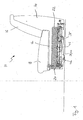
- the seat / reclining furniture 10 comprises according to FIG. 1 on the base standing base 12, to which a back portion 14 attached is that with a relative to the vertical inclined back pad 16 is provided.
- a back portion 14 attached is that with a relative to the vertical inclined back pad 16 is provided.
- On the base part 12 is a substantially horizontal arranged seat cushion 18 attached.
- the reclining / deck chair 10 further includes one of the base 12 in the Essentially rectilinear forward pull-out part 20, the in Fig. 1 in its basic position, which allows the sitting of persons shown is.
- the pull-out 20 has an additional cushion 22, the extended Pull-out 20 at substantially the same height as the seat cushion 18 of the base part 12 can be raised.
- the pull-out member 20 further includes a front frame member 24 and a rear frame part 26, each extending across the width of the sitting / lying furniture 10 extend (see Fig. 2a, 2b).
- the front frame part 24 is connected to two lateral frame members 28, which are seated extend.
- the lateral frame members 28 are over double angled Elbows 30 connected to the rear frame member 26, wherein the attaching to the rear frame member 26 end of the angle pieces 30 via the rear frame part 26 protrudes upward.
- FIG. 2 b shows one in the region of the rear frame part 26 Fig. 2a simplified representation, so that the interaction of the the rail support 32 mounted rail 34 with the rear Frame part 26 is better recognizable.
- the pull-out part 20 also comprises a composite of several parts Transformation fitting 38, by means of which the additional cushion 22 can be adjusted in height.
- the transformation fitting 38 has a triangular support lever 40, wherein at one corner of the Support lever 40, a roller 42 is mounted. At another corner of the Support lever 40 is a rotary roller 44 mounted, the additional, for horizontal axis of rotation of the rotary roller 44 has a vertical axis of rotation.
- the side parts of the base part 12 are on the inside with slide guides 46 provided by forming corresponding recesses are formed in the side parts of the base part 12.
- To the lateral ends of the rail 34 is a respective guide member 48th (see Fig. 2a) mounted in the respective slotted guide 46th is forced.
- the rail 34 is thus along the slotted guides 46 and thus in the direction of the depth of the sitting / lying furniture 10th traversable.
- the side parts of the base part 12 on the inside, each with one on each one spacer element 50 mounted straightening roller 52 provided so that they in the interior of the Base part 12 project and with the two side frame parts 28th of the pull-20 can interact.
- the axes of rotation of the straightening rollers 52 are vertical.
- the vertically oriented with its axis of rotation Retaining roller 58 is disposed at the rear of the rail carrier 32.
- a tension spring 60 is mounted, so that the rail carrier 32 in a sense between the elbow 30 and the retaining roller 58th is clamped.
- a stop 62 is provided, the one of the extended position of FIG. 3 outgoing adjustment the retaining roller 58 and thus the entire extension part 20 along of the rail carrier 32 is limited to one direction.
- the pull-out 20 by means of the front Frame part 24 along a first direction pulled forward, as in Fig. 2a illustrates by an arrow.
- the guide members 48 along the slide guides 46 after moved forward, with the lateral frame members 28 along the two Guiding rollers 52 of the base 12 slide.
- Front pulls the pull-20 with the rollers 42 on the floor. Due to the design of the slotted guide 46, the pull-out motion is essentially about a linear, horizontal movement.
- the extension of the pull-20 is by striking the two Guide members 48 at the front ends of the two slide guides 46 limited so that the position shown in Fig. 2a is achieved.
- the transformation fitting 38 In this position of the pull-out 20 is the transformation fitting 38 still in the same state as in Fig. 1, so that the additional cushion 22 is not raised yet.
- the elongated support lever 40 the transformation fitting 38 is substantially horizontal to the ground arranged.
- the additional cushion 22 are transferred to the extended position shown in FIG. 2b, wherein the Additional cushion 22 to substantially the same height as the seat cushion 18 of the base part 12 can be raised.
- the additional cushion 22 is in the pull-out position is arranged directly adjacent to the seat cushion 18, so that one of the two pads 18, 22 existing lying surface is created and serve the sitting / reclining furniture 10 as a reclining furniture can.
- the additional pad 22 is e.g. by means of a not shown Loop, for example, attached to the underside of the additional pad 22 may be pulled upwards, as in Fig. 2b by an arrow clarified.
- the additional pad 22nd is also slightly after offset front so that it is in this movement of the additional cushion 22nd is not a pure vertical, upward movement, which is illustrated by the inclination of the arrow relative to the vertical is.
- the additional cushion 22 is by means of a locking function of the transformation fitting 38 locked in the raised position shown in FIG. 2b, so that the pull-out 20 under the weight load of the additional cushion 22 and optionally a person located on the additional cushion 22 can not return to the lowered position shown in FIG. 2a.
- the Extended position according to FIG. 2b already represents a possible lying position of the sitting / lying furniture 10.
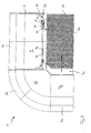
- the pull-out part 20 can between the pulled-out position shown in Fig. 2b and another functional position essentially straightforward be adjusted along a second direction, as in the plan view a seat / recliner 10 according to the invention as shown in FIG. 3 by a Arrow is clarified.
- a transverse movement of the pull-out 20 along the Front of the base part 12 so that the direction of the transverse displacement with the pull-out at an angle of substantially 90 degrees.
- a transverse movement from the extension position to the opposite Direction is due to the stop 62, on which the retaining roller 58th in the pull-out position, not possible.
- the further functional position can be a by the geometry of the seat / recliner 10 conditional, between the pull-out 20, and the corner element 66 and the other furniture element 70 located gap 74 be closed, so that the seat cushions 18, 72, 68 of the furniture elements 64, 70 and the corner member 66 and the additional cushion 22 of the pull-out 20 form a substantially closed lying surface. All available standing sitting / lying cushions 18, 22, 68, 72 of the sofa set can be used optimally.
- the pull-out 20 on the Rollers 42 In contrast to the pull-out, in which the pull-out 20 on the Rollers 42 is supported on the ground, but only a movement in Extraction allow, the pull-out 20 in the transverse movement about each having a vertical axis of rotation having turning rollers 44 on Ground supported.
- the pull-out 20 is in the original Transverse motion moves opposite direction.
- the pull-out position is attached by striking the on the mounting plate 56 Retaining rollers 58 reaches the stop 62.
- An inventive seat / reclining furniture 10 can with the two different Directions adjustable pull-out 20 in a simple way of a seat in a reclining furniture and be transformed back, where
- the option is given that the additional cushion 22 at the same Height as the seat cushion 18 of the base 12 different positions relative to the seat cushion 18 can take what in particular is of great advantage, if it is the furniture of the invention 10 is a corner set or an inventive furniture 10 as Leg member is part of such a corner trim.
Abstract
Description
Die Erfindung betrifft ein Sitz-/Liegemöbel nach dem Oberbegriff des Anspruchs 1.The invention relates to a sitting / lying furniture according to the preamble of Claim 1.
Derartige Sitz-/Liegemöbel sind grundsätzlich bekannt. Bei diesen bekannten Sitz-/Liegemöbeln, beispielsweise einem Sofa oder einem Sessel, kann das Sitz-/Liegemöbel durch Einschieben bzw. Ausziehen des Ausziehteils entweder in ein Sitz- oder ein Liegemöbel verwandelt werden. Bei einem solchen Sitz-/Liegemöbel kann in der Ausziehstellung das am Ausziehteil angeordnete Zusatzpolster angehoben werden, um mit dem Sitzpolster des Basisteils eine gemeinsame Liegefläche zu bilden.Such seating / reclining furniture are basically known. In these known Sitting / lying furniture, for example a sofa or an armchair, can the sitting / lying furniture by inserting or removing the pull-out be transformed into either a sitting or a reclining furniture. at Such a sitting / lying furniture can in the pull-out the on Extending part arranged additional upholstery can be raised with the Seat cushion of the base part to form a common bed.
Es ist das der Erfindung zugrunde liegende Problem (Aufgabe), ein Sitz-/Liegemöbel der eingangs genannten Art zu schaffen, das möglichst vielseitig einsetzbar ist, insbesondere als eine oder in Verbindung mit einer Couchgarnitur oder Wohnlandschaft.It is the problem underlying the invention (task), a sitting / lying furniture to create the type mentioned, the most versatile can be used, in particular as one or in conjunction with a Couchgarnitur or living area.
Die Lösung dieser Aufgabe erfolgt durch die Merkmale des Anspruchs 1.The solution of this object is achieved by the features of claim 1.
Bei dem erfindungsgemäßen Sitz-/Liegemöbel ist vorgesehen, dass das Ausziehteil zwischen der Ausziehstellung und der weiteren Funktionsstellung verstellbar ist. Die weitere Verstellbewegung erfolgt entlang einer Richtung, die von der zwischen der Grundstellung und der Ausziehstellung des Ausziehteils gebildeten Richtung abweicht, wobei insbesondere die beiden Richtungen um 90 Grad gegeneinander gedreht sind. In the sitting / lying furniture according to the invention it is provided that the Extractor between the extension position and the other functional position is adjustable. The further adjustment movement takes place along a Direction of the between the basic position and the pull-out position of the pull-out part deviates, in particular the two directions are rotated 90 degrees against each other.
Ein Vorteil des erfindungsgemäßen Sitz-/Liegemöbels besteht darin, dass zur Ausbildung der Liegefläche das Zusatzpolster des Ausziehteils auf verschiedene Funktionsstellungen eingestellt werden kann. Das Zusatzpolster kann während der Verstellbewegung zwischen der Ausziehstellung und der weiteren Funktionsstellung auf im Wesentlichen gleicher Höhe wie das Sitzpolster des Basisteils sein oder jede beliebige andere Höhenlage einnehmen. Die Verstellbewegung kann eine kontinuierliche Verstellbewegung sein, die in der gewünschten weiteren Funktionsstellung angehalten wird.An advantage of the sitting / lying furniture according to the invention is that for forming the lying surface, the additional cushion of the pull-out on various functional positions can be adjusted. The additional cushion can during the adjustment between the extended position and the further functional position at substantially the same height as the seat cushion of the base part or any other altitude taking. The adjustment can be a continuous adjustment be stopped in the desired further functional position becomes.
Die Verstellbarkeit der Ausziehteils zwischen der Ausziehstellung und der weiteren Funktionsstellung ermöglicht es insbesondere, dass bei einem Sitz-/Liegemöbel, das aus mehreren Möbelelementen zusammengesetzt und/oder "über ein Eck" ausgebildet ist, durch die Sitzpolster und das Zusatzpolster des Ausziehteils eine im Wesentlichen geschlossene, durchgehende Liegefläche gebildet wird. In der Ausziehstellung durch die Geometrie beispielsweise einer Eck-Anordnung eventuell bedingte Lücken in der Liegefläche des Sitz-/Liegemöbels können hierdurch vermieden werden.The adjustability of the Ausziehteils between the extended position and the further functional position makes it possible in particular for a Seating / reclining furniture composed of several furniture elements and / or "over a corner" is formed by the seat cushion and the Additional cushion of Ausziehteils a substantially closed, continuous Lying surface is formed. In the extraction position by the geometry For example, a corner arrangement possibly caused gaps in The lying surface of the sitting / lying furniture can be avoided.
Vorteilhafte Ausführungsformen der Erfindung sind in den Unteransprüchen, der Beschreibung und der Zeichnung angegeben.Advantageous embodiments of the invention are defined in the subclaims, the description and the drawing.
Nachfolgend wird die Erfindung rein beispielhaft anhand einer vorteilhaften Ausführungsform und unter Bezugnahme auf die beigefügte Zeichnung beschrieben. Es zeigen:
- Fig. 1
- eine schematische Seitenansicht eines erfindungsgemäßen Sitz-/Liegemöbels in der Grundstellung mit einem Basisteil und einem Ausziehteil,
- Fig. 2a und 2b
- schematische Seitenansichten des erfindungsgemäßen Sitz-/Liegemöbels von Fig. 1 in einer ausgezogenen Stellung des Ausziehteils mit abgesenktem und angehobenem Zusatzpolster, und
- Fig. 3
- eine schematische Draufsicht eines erfindungsgemäßen Sitz-/Liegemöbels in der Ausziehstellung, das zwei Möbelelemente und eine Eckelement umfasst.
- Fig. 1
- a schematic side view of a sitting / lying furniture according to the invention in the basic position with a base part and an extractable part,
- Fig. 2a and 2b
- schematic side views of the seat / reclining furniture according to the invention of Figure 1 in an extended position of the Ausziehteils with lowered and raised additional cushion, and
- Fig. 3
- a schematic plan view of a sitting / lying furniture according to the invention in the extended position, comprising two furniture elements and a corner element.
Das erfindungsgemäße Sitz-/Liegemöbel 10 umfasst gemäß Fig. 1 ein auf
dem Boden stehendes Basisteil 12, an dem ein Rückenteil 14 angebracht
ist, das mit einem gegenüber der Vertikalen geneigten Rückenpolster 16
versehen ist. Auf dem Basisteil 12 ist ein im Wesentlichen horizontal
angeordnetes Sitzpolster 18 angebracht.The seat / reclining
Das Sitz-/Liegemöbel 10 umfasst ferner ein aus dem Basisteil 12 im
Wesentlichen geradlinig nach vorne ausziehbares Ausziehteil 20, das in
Fig. 1 in seiner Grundstellung, die das Sitzen von Personen erlaubt, dargestellt
ist. Das Ausziehteil 20 weist ein Zusatzpolster 22, das bei ausgezogenem
Ausziehteil 20 auf im Wesentlichen gleiche Höhe wie das Sitzpolster
18 des Basisteils 12 angehoben werden kann.The reclining /
Das Ausziehteil 20 weist des Weiteren ein vorderes Rahmenteil 24 und ein
hinteres Rahmenteil 26 auf, die sich jeweils über die Breite des Sitz-/Liegemöbels
10 erstrecken (vgl. Fig. 2a, 2b). Das vordere Rahmenteil 24
ist mit zwei seitlichen Rahmenteilen 28 verbunden, die sich in Sitzrichtung
erstrecken. Die seitlichen Rahmenteile 28 sind über doppelt gewinkelte
Winkelstücke 30 mit dem hinteren Rahmenteil 26 verbunden, wobei
das am hinteren Rahmenteil 26 befestige Ende der Winkelstücke 30 über
das hintere Rahmenteil 26 nach oben hinaus vorsteht.The pull-out
Am Ausziehteil 20 ist ferner ein sich ebenfalls über die Breite des Sitz-/Liegemöbels
10 erstreckender Schienenträger 32 vorgesehen, an dessen
Vorderseite eine Profilschiene 34 befestigt ist, an der Führungsorgane 36
zwangsgeführt sind, die jeweils an dem über das hintere Rahmenteil 26
nach oben vorstehenden Ende des Winkelstücks 30 angebracht sind. Das
hintere Rahmenteil 26 ist somit entlang des Schienenträgers 32 und
damit in Richtung der Breite des Sitz-/Liegemöbels 10 verfahrbar.On Ausziehteil 20 is also a also across the width of the sitting / lying
Fig. 2b zeigt dabei eine im Bereich des hinteren Rahmenteils 26 gegenüber
Fig. 2a vereinfachte Darstellung, so dass das Zusammenwirken der an
dem Schienenträger 32 befestigten Profilschiene 34 mit dem hinteren
Rahmenteil 26 besser erkennbar ist.FIG. 2 b shows one in the region of the
Das Ausziehteil 20 umfasst außerdem einen aus mehreren Teilen zusammengesetzten
Verwandlungsbeschlag 38, mittels dem das Zusatzpolster
22 in seiner Höhe verstellt werden kann. Der Verwandlungsbeschlag 38
weist einen dreiecksförmigen Stützhebel 40 auf, wobei an einem Eck des
Stützhebels 40 eine Rolle 42 gelagert ist. An einem weiteren Eck des
Stützhebels 40 ist eine Drehrolle 44 gelagert, die eine zusätzliche, zur
horizontalen Drehachse der Drehrolle 44 vertikale Drehachse aufweist.The pull-out
Die Seitenteile des Basisteils 12 sind an der Innenseite mit Kulissenführungen
46 versehen, die durch Ausbilden von entsprechenden Aussparungen
in den Seitenteilen des Basisteils 12 gebildet werden. An den
seitlichen Enden der Profilschiene 34 ist jeweils ein Führungsorgan 48
(vgl. Fig. 2a) angebracht, das in der jeweiligen Kulissenführung 46
zwangsgeführt ist. Die Profilschiene 34 ist somit entlang der Kulissenführungen
46 und damit in Richtung der Tiefe des Sitz-/Liegemöbels 10
verfahrbar.The side parts of the
Zur seitlichen Führung des Ausziehteils 20 beim Ausfahren bzw. Einschieben
aus dem bzw. in das Basisteil 12 sind die Seitenteile des Basisteils
12 an der Innenseite jeweils mit einer an jeweils einem Abstandselement
50 gelagerten Richtrolle 52 versehen, so dass diese in das Innere des
Basisteils 12 vorstehen und mit den beiden seitlichen Rahmenteilen 28
des Ausziehteils 20 zusammenwirken können. Die Drehachsen der Richtrollen
52 verlaufen vertikal.For lateral guidance of the
Zur Unterstützung der Verstellbewegung des hinteren Rahmenteils 26
entlang des Schienenträgers 32 bei ausgefahrenem Ausziehteil 20 ist an
dem hinteren Rahmenteil 26 eine Montageplatte 54 angebracht (Fig. 3), an
die rechtwinklig eine weitere Montageplatte 56 angebracht ist, an welche
eine Halterolle 58 angelenkt ist. Die mit ihrer Drehachse vertikal orientierte
Halterolle 58 ist an der Rückseite des Schienenträgers 32 angeordnet.
Zwischen der weiteren Montageplatte 56 und einem der beiden Winkelstücke
30 ist eine Zugfeder 60 angebracht, so dass der Schienenträger 32
gewissermaßen zwischen dem Winkelstück 30 und der Halterolle 58
eingespannt ist.To assist the adjustment movement of the
An der Rückseite des Schienenträgers 32 ist ein Anschlag 62 vorgesehen,
der eine von der Ausziehstellung gemäß Fig. 3 ausgehende Verstellbewegung
der Halterolle 58 und damit des gesamten Ausziehteils 20 entlang
des Schienenträgers 32 auf eine Richtung beschränkt.At the back of the
Zusätzlich zu einem das Ausziehteil 20 umfassenden Möbelelement 64
weist das Sitz-/Liegemöbel 10 gemäß der Fig. 3 ein an das Möbelelement
64 anschließendes Eckelement 66 mit einem Sitzpolster 68 und ein weiteres
Möbelelement 70 mit einem Sitzpolster 72 auf. Insgesamt ist hier das
erfindungsgemäße Möbel 10 somit eine auch als Wohnlandschaft bezeichnete
Eckgarnitur, d.h. das mit dem Ausziehteil 20 versehene Basisteil 12
ist hier eines von zwei jeweils einen Bestandteil der Eckgarnitur bildenden
Schenkelelementen 64, 70, die jeweils seitlich an das Eckelement 66
angebunden sind.In addition to the pull-out 20 comprehensive furniture element 64th
has the sitting / lying
Nachfolgend wird die Funktionsweise eines erfindungsgemäßen Sitz-/Liegemöbels
10 unter Bezugnahme auf die Fig. 1 - 3 beschrieben:
Um das Sitz-/Liegemöbel 10 von der Grundstellung in eine ausgezogene
Stellung zu überführen, wird das Ausziehteil 20 mittels des vorderen
Rahmenteils 24 entlang einer ersten Richtung nach vorne gezogen, wie in
Fig. 2a durch einen Pfeil verdeutlicht. Beim Ausfahren des Ausziehteils 20
werden die Führungsorgane 48 entlang der Kulissenführungen 46 nach
vorne verfahren, wobei die seitlichen Rahmenteile 28 entlang der beiden
Richtrollen 52 des Basisteils 12 gleiten. Vorne rollt das Ausziehteil 20 mit
den Rollen 42 auf dem Boden. Aufgrund der Ausgestaltung der Kulissenführung
46 handelt es sich bei der Ausziehbewegung im Wesentlichen um
eine lineare, und zwar horizontale Bewegung. To move the reclining /
Das Ausfahren des Ausziehteils 20 wird durch Anschlagen der beiden
Führungsorgane 48 an den vorderen Enden der beiden Kulissenführungen
46 begrenzt, so dass die in Fig. 2a gezeigte Stellung erreicht wird. In
dieser Stellung des Ausziehteils 20 befindet sich der Verwandlungsbeschlag
38 noch in demselben Zustand wie in Fig. 1, so dass das Zusatzpolster
22 noch nicht angehoben ist. Der lang gestreckte Stützhebel 40
des Verwandlungsbeschlags 38 ist im Wesentlichen horizontal zum Boden
angeordnet.The extension of the pull-20 is by striking the two
Aus der Stellung des Ausziehteils 20 gemäß Fig. 2a kann das Zusatzpolster
22 in die Ausziehstellung gemäß Fig. 2b überführt werden, wobei das
Zusatzpolster 22 auf im Wesentlichen die gleiche Höhe wie das Sitzpolster
18 des Basisteils 12 angehoben werden kann. Das Zusatzpolster 22 ist in
der Ausziehstellung unmittelbar an das Sitzpolster 18 angrenzend angeordnet,
so dass eine aus den beiden Polstern 18, 22 bestehende Liegefläche
geschaffen wird und das Sitz-/Liegemöbel 10 als Liegemöbel dienen
kann.From the position of the pull-out 20 as shown in FIG. 2a, the
Dazu wird das Zusatzpolster 22 z.B. mittels einer nicht dargestellten
Schlaufe, die beispielsweise an der Unterseite des Zusatzpolsters 22 angebracht
sein kann, nach oben gezogen, wie in Fig. 2b durch einen Pfeil
verdeutlicht. Beim Hochziehen wird das Zusatzpolster 22 auch leicht nach
vorne versetzt, so dass es sich bei dieser Bewegung des Zusatzpolsters 22
nicht um eine reine vertikale, nach oben gerichtete Bewegung handelt,
was durch die Neigung des Pfeils gegenüber der Vertikalen veranschaulicht
ist.For this, the
Das Zusatzpolster 22 wird mittels einer Feststellfunktion des Verwandlungsbeschlags
38 in der angehoben Stellung gemäß Fig. 2b arretiert, so
dass das Ausziehteil 20 unter der Gewichtsbelastung des Zusatzpolsters
22 und gegebenenfalls einer auf dem Zusatzpolster 22 befindlichen Person
nicht in die abgesenkte Stellung gemäß Fig. 2a zurückkehren kann. Die
Ausfahrstellung gemäß Fig. 2b stellt bereits eine mögliche Liegestellung
des Sitz-/Liegemöbels 10 dar.The
Beim Hochziehen des Zusatzpolsters 22 wird der Verwandlungsbeschlag
38 des Ausziehteils 20 derart wirksam, dass der Stützhebel 40 aus der in
Fig. 2a im Wesentlichen horizontalen Lage in eine aufrechtere Lage überführt
wird. Die Abstützung des Stützhebels 40 am Boden schaltet dabei
automatisch von den Rollen 42, die eine Bewegung des Ausziehteils 20
lediglich entlang der Ausziehrichtung erlauben, auf die ebenfalls am
Stützhebel befestigten Drehrollen 44 um.When pulling up the
Das Ausziehteil 20 kann zwischen der in Fig. 2b dargestellten Ausziehstellung
und einer weiteren Funktionsstellung im Wesentlichen geradlinig
entlang einer zweiten Richtung verstellt werden, wie in der Draufsicht
eines erfindungsgemäßen Sitz-/Liegemöbels 10 gemäß Fig. 3 durch einen
Pfeil verdeutlicht ist. Bei der Bewegung entlang der zweiten Richtung
handelt es sich um eine Querbewegung des Ausziehteils 20 entlang der
Vorderseite des Basisteils 12, so dass die Richtung der Querverschiebung
mit der Ausziehrichtung einen Winkel von im Wesentlichen 90 Grad einschließt.
Eine Querbewegung aus der Ausziehstellung in die entgegengesetzte
Richtung ist aufgrund des Anschlags 62, an dem die Halterolle 58
in der Ausziehstellung ansteht, nicht möglich.The pull-out
In der weiteren Funktionsstellung kann eine durch die Geometrie des Sitz-/Liegemöbels
10 bedingte, zwischen dem Ausziehteil 20, und dem Eckelement
66 und dem weiteren Möbelelement 70 befindliche Lücke 74
geschlossen werden, so dass die Sitzpolster 18, 72, 68 der Möbelelemente
64, 70 und des Eckelements 66 und das Zusatzpolster 22 des Ausziehteils
20 eine im Wesentlichen geschlossene Liegefläche bilden. Alle zur Verfügung
stehenden Sitz-/Liegepolster 18, 22, 68, 72 der Couchgarnitur können
so optimal genutzt werden.In the further functional position can be a by the geometry of the seat /
Im Gegensatz zu der Ausziehbewegung, bei der das Ausziehteil 20 über die
Rollen 42 am Boden abgestützt wird, die jedoch lediglich eine Bewegung in
Ausziehrichtung erlauben, wird das Ausziehteil 20 bei der Querbewegung
über die jeweils eine vertikale Drehachse aufweisenden Drehrollen 44 am
Boden abgestützt.In contrast to the pull-out, in which the pull-out 20 on the
Bei der Querbewegung entlang der zweiten Richtung gleiten die an den
beiden Winkelstücken angebrachten Führungsorgane zwangsgeführt
entlang der Profilschiene. Die Halterolle 58 läuft dabei entlang der Rückseite
des Schienenträgers 32. Bei der Verstellbewegung quer zur Vorderseite
des Sitz-/ Liegemöbels 10 bleiben der Schienenträger 32 und die
daran angebrachte Profilschiene zwischen den beiden Seitenwänden des
Basisteils 12 in Ruhe und werden nicht verstellt.In the transverse movement along the second direction to slide on the
two elbows mounted guide members forcibly guided
along the rail. The retaining
Um das Sitz-/Liegemöbel 10 von der eine geschlossene Liegefläche aufweisenden
weiteren Funktionsstellung in die Ausziehstellung gemäß Fig. 3
bzw. Fig. 2b zurück zu verstellen, wird das Ausziehteil 20 in die der ursprünglichen
Querbewegung entgegengesetzte Richtung bewegt. Die Ausziehstellung
wird durch Anschlagen der an der Montageplatte 56 angebrachten
Halterolle 58 an dem Anschlag 62 erreicht.To the sitting / lying
Das Überführen des Sitz-/Liegemöbels 10 von der Ausziehstellung des
Ausziehteils 20 mit angehobenem Zusatzpolster 22 gemäß Fig. 2b in die
ausgezogene Stellung mit abgesenktem Zusatzpolster 22 gemäß Fig. 2a
wird durch eine Freigabefunktion des Verwandlungsbeschlags 38 erreicht,
die die Arretierung des Zusatzpolsters 22 auf im Wesentlichen gleicher
Höhe wie das Sitzpolster 18 des Basisteils 12 aufhebt, so dass das Zusatzpolster
22 abgesenkt werden kann.The transfer of the sitting / lying
Um das Sitz-/Liegemöbel 10 von der ausgezogenen Stellung gemäß Fig. 2a
in die Grundstellung gemäß Fig. zurück zu verwandeln, wird das Ausziehteil
20 in das Basisteil 12 zurück geschoben. Die seitlichen Rahmenteile
28 des Ausziehteils 20 gleiten dabei entlang der Richtrollen 52 des
Basisteils 12. Mit dem Anschlagen der Führungsorgane 48 an den hinteren
Enden der Kulissenführungen 46 ist die Grundstellung erreicht.To the sitting / lying
Ein erfindungsgemäßes Sitz-/Liegemöbel 10 kann mit dem in zwei verschiedene
Richtungen verstellbaren Ausziehteil 20 auf einfache Weise von
einem Sitz- in eine Liegemöbel und zurück verwandelt werden, wobei
zusätzlich die Option gegeben ist, dass das Zusatzpolster 22 bei gleicher
Höhe wie das Sitzpolster 18 des Basisteils 12 verschiedene Positionen
relativ zu dem Sitzpolster 18 einnehmen kann, was insbesondere dann
von großem Vorteil ist, wenn es sich bei dem erfindungsgemäßen Möbel
10 um eine Eckgarnitur handelt bzw. ein erfindungsgemäßes Möbel 10 als
Schenkelelement ein Bestandteil einer solchen Eckgarnitur ist. An inventive seat /
- 1010
- Sitz-/ LiegemöbelSitting / lying furniture
- 1212
- Basisteilbase
- 1414
- Rückenteilback
- 1616
- Rückenposterback Poster
- 1818
- Sitzpolsterseat cushion
- 2020
- Ausziehteilpull-out
- 2222
- Zusatzpolsteradditional cushion
- 2424
- vorderes Rahmenteilfront frame part
- 2626
- hinteres Rahmenteilrear frame part
- 2828
- seitliches Rahmenteillateral frame part
- 3030
- Winkelstückelbow
- 3232
- Schienenträgerrail support
- 3434
- Profilschienerail
- 3636
- Führungsorganmanagement body
- 3838
- Verwandlungsbeschlagtransformation fitting
- 4040
- Stützhebelsupport lever
- 4242
- Rollerole
- 4444
- Drehrollespinning reel
- 4646
- Kulissenführunglink guide
- 4848
- Führungsorganmanagement body
- 5050
- Abstandselementspacer
- 5252
- Richtrollestraightening roller
- 5454
- Montageplattemounting plate
- 5656
- Montageplattemounting plate
- 5858
- Halterolleholding roller
- 6060
- Zugfedermainspring
- 6262
- Anschlag attack
- 6464
- Möbelelementfurniture element
- 6666
- EckelementCorner
- 6868
- Sitzpolsterseat cushion
- 7070
- Möbelelementfurniture element
- 7272
- Sitzpolsterseat cushion
- 7474
- Lückegap
Claims (6)
dadurch gekennzeichnet, dass das Ausziehteil (20) zwischen der Ausziehstellung und einer weiteren Funktionsstellung entlang einer zweiten, von der ersten Richtung insbesondere um 90 Grad abweichenden Richtung verstellbar ist.Sitting / lying furniture (10) with at least one at least one seat cushion (18) having base part (12) and at least one between a basic position and a Ausziehstellung along a first direction movable extension part (20) on which at least one additional cushion (22) arranged vertically adjustable is
characterized in that the pull-out part (20) is adjustable between the extension position and a further functional position along a second direction deviating from the first direction, in particular by 90 degrees.
dadurch gekennzeichnet, dass die Bewegung des Ausziehteils (20) zwischen der Grundstellung und der Ausziehstellung und/oder die Bewegung des Ausziehteils (20) zwischen der Ausziehstellung und der weiteren Funktionsstellung zumindest im Wesentlichen eine lineare Bewegung ist.Sitting / lying furniture according to claim 1,
characterized in that the movement of the Ausziehteils (20) between the basic position and the Ausziehstellung and / or the movement of the Ausziehteils (20) between the extended position and the further functional position is at least substantially a linear movement.
dadurch gekennzeichnet, dass in der Ausziehstellung das Zusatzpolster (22) des Ausziehteils (20) auf im Wesentlichen die gleiche Höhe wie das Sitzpolster (18) des Basisteils (12) anhebbar ist. Sitting / lying furniture according to claim 1 or 2,
characterized in that in the extended position, the additional cushion (22) of the extension part (20) can be raised to substantially the same height as the seat cushion (18) of the base part (12).
dadurch gekennzeichnet, dass zur Abstützung des Ausziehteils (20) am Boden bei der Bewegung entlang der ersten Richtung einerseits und entlang der zweiten Richtung andererseits verschiedene Stützmittel (42, 44), insbesondere Rollen, vorgesehen sind.Sitting / lying furniture according to one of the preceding claims,
characterized in that for supporting the Ausziehteils (20) on the ground in the movement along the first direction on the one hand and along the second direction on the other hand different support means (42, 44), in particular rollers, are provided.
dadurch gekennzeichnet, dass das Ausziehteil (20) eine schwenkbar gelagerte Stützeinrichtung (40) umfasst, die durch Anheben des Zusatzpolsters (22) automatisch zwischen den verschiedenen Stützmitteln (42, 44) umschaltet.Sitting / lying furniture according to claim 4,
characterized in that the pull-out member (20) comprises a pivotally mounted support means (40) which automatically switches between the various support means (42, 44) by lifting the auxiliary pad (22).
dadurch gekennzeichnet, dass zumindest ein an das Basisteil (12) anschließendes Eckelement (66) und/oder weiteres Möbelelement (70) vorgesehen ist, das wenigstens ein weiteres Sitzpolster (68, 72) aufweist, wobei in der weiteren Funktionsstellung des Ausziehteils (20) dessen Zusatzpolster (22) und die Sitzpolster (18, 68, 72) eine zumindest im Wesentlichen geschlossene Sitz-/Liegefläche bilden.Sitting / lying furniture according to one of the preceding claims,
characterized in that at least one of the base part (12) adjoining corner element (66) and / or further furniture element (70) is provided which has at least one further seat cushion (68, 72), wherein in the further functional position of the pull-out (20) the additional cushion (22) and the seat cushion (18, 68, 72) form an at least substantially closed sitting / lying surface.
Applications Claiming Priority (2)
| Application Number | Priority Date | Filing Date | Title |
|---|---|---|---|
| DE20314567U DE20314567U1 (en) | 2003-09-19 | 2003-09-19 | Seating / reclining furniture |
| DE20314567U | 2003-09-19 |
Publications (3)
| Publication Number | Publication Date |
|---|---|
| EP1516564A2 true EP1516564A2 (en) | 2005-03-23 |
| EP1516564A3 EP1516564A3 (en) | 2005-03-30 |
| EP1516564B1 EP1516564B1 (en) | 2006-03-29 |
Family
ID=29796838
Family Applications (1)
| Application Number | Title | Priority Date | Filing Date |
|---|---|---|---|
| EP04022360A Active EP1516564B1 (en) | 2003-09-19 | 2004-09-20 | Adjustable sitting/lying furniture |
Country Status (3)
| Country | Link |
|---|---|
| EP (1) | EP1516564B1 (en) |
| AT (1) | ATE321475T1 (en) |
| DE (2) | DE20314567U1 (en) |
Citations (6)
| Publication number | Priority date | Publication date | Assignee | Title |
|---|---|---|---|---|
| US4672696A (en) * | 1985-03-27 | 1987-06-16 | Ferdinand Lusch Gmbh & Co. Kg. | Convertible sitting/reclining furniture article |
| DE19612315A1 (en) * | 1995-06-16 | 1996-12-19 | Couchmechanik Gmbh Freital | Convertible chair and settee with frame, seat and recliner elements and back rest |
| DE19604898A1 (en) * | 1996-02-10 | 1997-08-14 | Couchmechanik Gmbh Freital | Couch which folds-up to become chair |
| DE19747692A1 (en) * | 1996-12-18 | 1998-06-25 | Hoppe Kg Hodry Metallfab | Fitting for sofa bed |
| DE19838840C1 (en) * | 1998-08-27 | 2000-01-27 | Sichelschmidt Stanzwerk | Convertible seat and bed |
| US6588837B1 (en) * | 2000-11-01 | 2003-07-08 | Hill-Rom Services, Inc. | Chair with pull out sleep surface |
-
2003
- 2003-09-19 DE DE20314567U patent/DE20314567U1/en not_active Expired - Lifetime
-
2004
- 2004-09-20 EP EP04022360A patent/EP1516564B1/en active Active
- 2004-09-20 DE DE502004000398T patent/DE502004000398D1/en active Active
- 2004-09-20 AT AT04022360T patent/ATE321475T1/en active
Patent Citations (6)
| Publication number | Priority date | Publication date | Assignee | Title |
|---|---|---|---|---|
| US4672696A (en) * | 1985-03-27 | 1987-06-16 | Ferdinand Lusch Gmbh & Co. Kg. | Convertible sitting/reclining furniture article |
| DE19612315A1 (en) * | 1995-06-16 | 1996-12-19 | Couchmechanik Gmbh Freital | Convertible chair and settee with frame, seat and recliner elements and back rest |
| DE19604898A1 (en) * | 1996-02-10 | 1997-08-14 | Couchmechanik Gmbh Freital | Couch which folds-up to become chair |
| DE19747692A1 (en) * | 1996-12-18 | 1998-06-25 | Hoppe Kg Hodry Metallfab | Fitting for sofa bed |
| DE19838840C1 (en) * | 1998-08-27 | 2000-01-27 | Sichelschmidt Stanzwerk | Convertible seat and bed |
| US6588837B1 (en) * | 2000-11-01 | 2003-07-08 | Hill-Rom Services, Inc. | Chair with pull out sleep surface |
Also Published As
| Publication number | Publication date |
|---|---|
| DE502004000398D1 (en) | 2006-05-18 |
| ATE321475T1 (en) | 2006-04-15 |
| EP1516564B1 (en) | 2006-03-29 |
| DE20314567U1 (en) | 2003-12-18 |
| EP1516564A3 (en) | 2005-03-30 |
Similar Documents
| Publication | Publication Date | Title |
|---|---|---|
| DE102005016943B4 (en) | Ottoman | |
| DE3822574C2 (en) | ||
| DE2459908C3 (en) | Extension device for a footrest in an armchair | |
| DE2717331A1 (en) | CHAIR WITH ADJUSTABLE BACKREST | |
| DE19620871A1 (en) | Front car seat with adjustable seating length | |
| DE4133200A1 (en) | ADJUSTABLE ARMCHAIR | |
| EP2801293B1 (en) | Seating furniture and cover for same | |
| DE19620872A1 (en) | Front car seat with adjustable length and height | |
| EP2609834A1 (en) | Seating furniture and cover system for same | |
| DE10301326A1 (en) | Seating furniture, in particular armchairs | |
| DE1038733B (en) | Seating that can be transformed into a bed or couch | |
| DE202021103365U1 (en) | Sitting or lying furniture with a footrest | |
| EP1516564B1 (en) | Adjustable sitting/lying furniture | |
| AT406111B (en) | SEAT FURNITURE CONVERTIBLE INTO A BED | |
| EP1725140A1 (en) | Item of furniture for sitting and lying upon | |
| EP1118291A2 (en) | Seating furniture | |
| AT391068B (en) | Item of seating which can be converted into a couch | |
| DE19635635C1 (en) | Extra seat for couch | |
| DE3107415A1 (en) | Bench which can be converted into a sofa bed, and fitting therefor | |
| DE972073C (en) | Chair with adjustable seat and swiveling backrest | |
| AT372589B (en) | Seating and reclining furniture | |
| DE8017170U1 (en) | SEAT FURNITURE CONVERTIBLE INTO A BED | |
| DE2917992A1 (en) | Adjustable couch back and seat cushions - operate by using two side extensions on seat frame, with rollers and guide rails | |
| DE7912901U1 (en) | UPHOLSTERED ARMCHAIR OR COUCH WITH ADJUSTABLE SEAT AND BACK UPHOLSTERY | |
| DE1529552A1 (en) | Lever adjusting device for seating and reclining furniture |
Legal Events
| Date | Code | Title | Description |
|---|---|---|---|
| PUAI | Public reference made under article 153(3) epc to a published international application that has entered the european phase |
Free format text: ORIGINAL CODE: 0009012 |
|
| PUAL | Search report despatched |
Free format text: ORIGINAL CODE: 0009013 |
|
| AK | Designated contracting states |
Kind code of ref document: A2 Designated state(s): AT BE BG CH CY CZ DE DK EE ES FI FR GB GR HU IE IT LI LU MC NL PL PT RO SE SI SK TR |
|
| AX | Request for extension of the european patent |
Extension state: AL HR LT LV MK |
|
| AK | Designated contracting states |
Kind code of ref document: A3 Designated state(s): AT BE BG CH CY CZ DE DK EE ES FI FR GB GR HU IE IT LI LU MC NL PL PT RO SE SI SK TR |
|
| AX | Request for extension of the european patent |
Extension state: AL HR LT LV MK |
|
| 17P | Request for examination filed |
Effective date: 20050622 |
|
| GRAP | Despatch of communication of intention to grant a patent |
Free format text: ORIGINAL CODE: EPIDOSNIGR1 |
|
| AKX | Designation fees paid |
Designated state(s): AT BE BG CH CY CZ DE DK EE ES FI FR GB GR HU IE IT LI LU MC NL PL PT RO SE SI SK TR |
|
| GRAS | Grant fee paid |
Free format text: ORIGINAL CODE: EPIDOSNIGR3 |
|
| GRAA | (expected) grant |
Free format text: ORIGINAL CODE: 0009210 |
|
| AK | Designated contracting states |
Kind code of ref document: B1 Designated state(s): AT BE BG CH CY CZ DE DK EE ES FI FR GB GR HU IE IT LI LU MC NL PL PT RO SE SI SK TR |
|
| PG25 | Lapsed in a contracting state [announced via postgrant information from national office to epo] |
Ref country code: IT Free format text: LAPSE BECAUSE OF FAILURE TO SUBMIT A TRANSLATION OF THE DESCRIPTION OR TO PAY THE FEE WITHIN THE PRESCRIBED TIME-LIMIT;WARNING: LAPSES OF ITALIAN PATENTS WITH EFFECTIVE DATE BEFORE 2007 MAY HAVE OCCURRED AT ANY TIME BEFORE 2007. THE CORRECT EFFECTIVE DATE MAY BE DIFFERENT FROM THE ONE RECORDED. Effective date: 20060329 Ref country code: RO Free format text: LAPSE BECAUSE OF FAILURE TO SUBMIT A TRANSLATION OF THE DESCRIPTION OR TO PAY THE FEE WITHIN THE PRESCRIBED TIME-LIMIT Effective date: 20060329 Ref country code: PL Free format text: LAPSE BECAUSE OF FAILURE TO SUBMIT A TRANSLATION OF THE DESCRIPTION OR TO PAY THE FEE WITHIN THE PRESCRIBED TIME-LIMIT Effective date: 20060329 Ref country code: SK Free format text: LAPSE BECAUSE OF FAILURE TO SUBMIT A TRANSLATION OF THE DESCRIPTION OR TO PAY THE FEE WITHIN THE PRESCRIBED TIME-LIMIT Effective date: 20060329 Ref country code: SI Free format text: LAPSE BECAUSE OF FAILURE TO SUBMIT A TRANSLATION OF THE DESCRIPTION OR TO PAY THE FEE WITHIN THE PRESCRIBED TIME-LIMIT Effective date: 20060329 Ref country code: IE Free format text: LAPSE BECAUSE OF FAILURE TO SUBMIT A TRANSLATION OF THE DESCRIPTION OR TO PAY THE FEE WITHIN THE PRESCRIBED TIME-LIMIT Effective date: 20060329 Ref country code: GB Free format text: LAPSE BECAUSE OF FAILURE TO SUBMIT A TRANSLATION OF THE DESCRIPTION OR TO PAY THE FEE WITHIN THE PRESCRIBED TIME-LIMIT Effective date: 20060329 |
|
| REG | Reference to a national code |
Ref country code: GB Ref legal event code: FG4D Free format text: NOT ENGLISH |
|
| REG | Reference to a national code |
Ref country code: CH Ref legal event code: EP |
|
| REG | Reference to a national code |
Ref country code: IE Ref legal event code: FG4D Free format text: LANGUAGE OF EP DOCUMENT: GERMAN |
|
| REF | Corresponds to: |
Ref document number: 502004000398 Country of ref document: DE Date of ref document: 20060518 Kind code of ref document: P |
|
| PG25 | Lapsed in a contracting state [announced via postgrant information from national office to epo] |
Ref country code: BG Free format text: LAPSE BECAUSE OF FAILURE TO SUBMIT A TRANSLATION OF THE DESCRIPTION OR TO PAY THE FEE WITHIN THE PRESCRIBED TIME-LIMIT Effective date: 20060629 Ref country code: DK Free format text: LAPSE BECAUSE OF FAILURE TO SUBMIT A TRANSLATION OF THE DESCRIPTION OR TO PAY THE FEE WITHIN THE PRESCRIBED TIME-LIMIT Effective date: 20060629 Ref country code: SE Free format text: LAPSE BECAUSE OF FAILURE TO SUBMIT A TRANSLATION OF THE DESCRIPTION OR TO PAY THE FEE WITHIN THE PRESCRIBED TIME-LIMIT Effective date: 20060629 |
|
| PG25 | Lapsed in a contracting state [announced via postgrant information from national office to epo] |
Ref country code: ES Free format text: LAPSE BECAUSE OF FAILURE TO SUBMIT A TRANSLATION OF THE DESCRIPTION OR TO PAY THE FEE WITHIN THE PRESCRIBED TIME-LIMIT Effective date: 20060710 |
|
| PG25 | Lapsed in a contracting state [announced via postgrant information from national office to epo] |
Ref country code: PT Free format text: LAPSE BECAUSE OF FAILURE TO SUBMIT A TRANSLATION OF THE DESCRIPTION OR TO PAY THE FEE WITHIN THE PRESCRIBED TIME-LIMIT Effective date: 20060829 |
|
| PG25 | Lapsed in a contracting state [announced via postgrant information from national office to epo] |
Ref country code: BE Free format text: LAPSE BECAUSE OF NON-PAYMENT OF DUE FEES Effective date: 20060930 Ref country code: MC Free format text: LAPSE BECAUSE OF NON-PAYMENT OF DUE FEES Effective date: 20060930 |
|
| GBV | Gb: ep patent (uk) treated as always having been void in accordance with gb section 77(7)/1977 [no translation filed] |
Effective date: 20060329 |
|
| REG | Reference to a national code |
Ref country code: IE Ref legal event code: FD4D |
|
| PLBE | No opposition filed within time limit |
Free format text: ORIGINAL CODE: 0009261 |
|
| STAA | Information on the status of an ep patent application or granted ep patent |
Free format text: STATUS: NO OPPOSITION FILED WITHIN TIME LIMIT |
|
| 26N | No opposition filed |
Effective date: 20070102 |
|
| EN | Fr: translation not filed | ||
| BERE | Be: lapsed |
Owner name: HIMOLLA POLSTERMOBEL G.M.B.H. Effective date: 20060930 |
|
| PG25 | Lapsed in a contracting state [announced via postgrant information from national office to epo] |
Ref country code: GR Free format text: LAPSE BECAUSE OF FAILURE TO SUBMIT A TRANSLATION OF THE DESCRIPTION OR TO PAY THE FEE WITHIN THE PRESCRIBED TIME-LIMIT Effective date: 20060630 Ref country code: FR Free format text: LAPSE BECAUSE OF FAILURE TO SUBMIT A TRANSLATION OF THE DESCRIPTION OR TO PAY THE FEE WITHIN THE PRESCRIBED TIME-LIMIT Effective date: 20070309 Ref country code: CZ Free format text: LAPSE BECAUSE OF FAILURE TO SUBMIT A TRANSLATION OF THE DESCRIPTION OR TO PAY THE FEE WITHIN THE PRESCRIBED TIME-LIMIT Effective date: 20060329 |
|
| PG25 | Lapsed in a contracting state [announced via postgrant information from national office to epo] |
Ref country code: EE Free format text: LAPSE BECAUSE OF FAILURE TO SUBMIT A TRANSLATION OF THE DESCRIPTION OR TO PAY THE FEE WITHIN THE PRESCRIBED TIME-LIMIT Effective date: 20060329 Ref country code: FI Free format text: LAPSE BECAUSE OF FAILURE TO SUBMIT A TRANSLATION OF THE DESCRIPTION OR TO PAY THE FEE WITHIN THE PRESCRIBED TIME-LIMIT Effective date: 20060329 |
|
| PG25 | Lapsed in a contracting state [announced via postgrant information from national office to epo] |
Ref country code: TR Free format text: LAPSE BECAUSE OF FAILURE TO SUBMIT A TRANSLATION OF THE DESCRIPTION OR TO PAY THE FEE WITHIN THE PRESCRIBED TIME-LIMIT Effective date: 20060329 Ref country code: HU Free format text: LAPSE BECAUSE OF FAILURE TO SUBMIT A TRANSLATION OF THE DESCRIPTION OR TO PAY THE FEE WITHIN THE PRESCRIBED TIME-LIMIT Effective date: 20060930 Ref country code: LU Free format text: LAPSE BECAUSE OF NON-PAYMENT OF DUE FEES Effective date: 20060920 |
|
| PG25 | Lapsed in a contracting state [announced via postgrant information from national office to epo] |
Ref country code: CY Free format text: LAPSE BECAUSE OF FAILURE TO SUBMIT A TRANSLATION OF THE DESCRIPTION OR TO PAY THE FEE WITHIN THE PRESCRIBED TIME-LIMIT Effective date: 20060329 Ref country code: FR Free format text: LAPSE BECAUSE OF FAILURE TO SUBMIT A TRANSLATION OF THE DESCRIPTION OR TO PAY THE FEE WITHIN THE PRESCRIBED TIME-LIMIT Effective date: 20060329 |
|
| PGFP | Annual fee paid to national office [announced via postgrant information from national office to epo] |
Ref country code: CH Payment date: 20170921 Year of fee payment: 14 |
|
| PGFP | Annual fee paid to national office [announced via postgrant information from national office to epo] |
Ref country code: AT Payment date: 20170922 Year of fee payment: 14 Ref country code: NL Payment date: 20170921 Year of fee payment: 14 |
|
| PGFP | Annual fee paid to national office [announced via postgrant information from national office to epo] |
Ref country code: DE Payment date: 20171129 Year of fee payment: 14 |
|
| REG | Reference to a national code |
Ref country code: DE Ref legal event code: R119 Ref document number: 502004000398 Country of ref document: DE |
|
| REG | Reference to a national code |
Ref country code: CH Ref legal event code: PL |
|
| REG | Reference to a national code |
Ref country code: NL Ref legal event code: MM Effective date: 20181001 |
|
| REG | Reference to a national code |
Ref country code: AT Ref legal event code: MM01 Ref document number: 321475 Country of ref document: AT Kind code of ref document: T Effective date: 20180920 |
|
| PG25 | Lapsed in a contracting state [announced via postgrant information from national office to epo] |
Ref country code: NL Free format text: LAPSE BECAUSE OF NON-PAYMENT OF DUE FEES Effective date: 20181001 |
|
| PG25 | Lapsed in a contracting state [announced via postgrant information from national office to epo] |
Ref country code: DE Free format text: LAPSE BECAUSE OF NON-PAYMENT OF DUE FEES Effective date: 20190402 |
|
| PG25 | Lapsed in a contracting state [announced via postgrant information from national office to epo] |
Ref country code: CH Free format text: LAPSE BECAUSE OF NON-PAYMENT OF DUE FEES Effective date: 20180930 Ref country code: LI Free format text: LAPSE BECAUSE OF NON-PAYMENT OF DUE FEES Effective date: 20180930 |
|
| PG25 | Lapsed in a contracting state [announced via postgrant information from national office to epo] |
Ref country code: AT Free format text: LAPSE BECAUSE OF NON-PAYMENT OF DUE FEES Effective date: 20180920 |