EP1514522A1 - Bone screw - Google Patents
Bone screw Download PDFInfo
- Publication number
- EP1514522A1 EP1514522A1 EP04021636A EP04021636A EP1514522A1 EP 1514522 A1 EP1514522 A1 EP 1514522A1 EP 04021636 A EP04021636 A EP 04021636A EP 04021636 A EP04021636 A EP 04021636A EP 1514522 A1 EP1514522 A1 EP 1514522A1
- Authority
- EP
- European Patent Office
- Prior art keywords
- recess
- extension
- screw
- bone screw
- screw head
- Prior art date
- Legal status (The legal status is an assumption and is not a legal conclusion. Google has not performed a legal analysis and makes no representation as to the accuracy of the status listed.)
- Granted
Links
- 210000000988 bone and bone Anatomy 0.000 title claims description 70
- 230000004308 accommodation Effects 0.000 abstract 1
- 210000002414 leg Anatomy 0.000 description 17
- 239000000834 fixative Substances 0.000 description 13
- 238000003780 insertion Methods 0.000 description 12
- 230000037431 insertion Effects 0.000 description 12
- 230000007704 transition Effects 0.000 description 5
- 238000006073 displacement reaction Methods 0.000 description 3
- 230000002093 peripheral effect Effects 0.000 description 3
- 239000007943 implant Substances 0.000 description 2
- 238000004519 manufacturing process Methods 0.000 description 2
- 230000006641 stabilisation Effects 0.000 description 2
- 238000011105 stabilization Methods 0.000 description 2
- 210000000689 upper leg Anatomy 0.000 description 2
- 239000003795 chemical substances by application Substances 0.000 description 1
- 230000008878 coupling Effects 0.000 description 1
- 238000010168 coupling process Methods 0.000 description 1
- 238000005859 coupling reaction Methods 0.000 description 1
- 230000001419 dependent effect Effects 0.000 description 1
- 238000001514 detection method Methods 0.000 description 1
- 238000005516 engineering process Methods 0.000 description 1
- 230000002349 favourable effect Effects 0.000 description 1
- 238000002513 implantation Methods 0.000 description 1
- 239000000463 material Substances 0.000 description 1
- 238000000034 method Methods 0.000 description 1
- 230000003716 rejuvenation Effects 0.000 description 1
- 238000011144 upstream manufacturing Methods 0.000 description 1
Images


Classifications
-
- A—HUMAN NECESSITIES
- A61—MEDICAL OR VETERINARY SCIENCE; HYGIENE
- A61B—DIAGNOSIS; SURGERY; IDENTIFICATION
- A61B17/00—Surgical instruments, devices or methods, e.g. tourniquets
- A61B17/56—Surgical instruments or methods for treatment of bones or joints; Devices specially adapted therefor
- A61B17/58—Surgical instruments or methods for treatment of bones or joints; Devices specially adapted therefor for osteosynthesis, e.g. bone plates, screws, setting implements or the like
- A61B17/68—Internal fixation devices, including fasteners and spinal fixators, even if a part thereof projects from the skin
- A61B17/70—Spinal positioners or stabilisers ; Bone stabilisers comprising fluid filler in an implant
- A61B17/7001—Screws or hooks combined with longitudinal elements which do not contact vertebrae
- A61B17/7041—Screws or hooks combined with longitudinal elements which do not contact vertebrae with single longitudinal rod offset laterally from single row of screws or hooks
Definitions
- the invention relates to a bone screw for attachment of a Spinal fixative, especially as pedicle screw, with a fixable in a bone, in particular vertebrae Threaded screw shaft for screwing into the bone and with a screw head with a mounting area for a Fastening device, by means of which the spinal fixer can be fixed, wherein the mounting portion is a threaded portion for fixing the fastening device has and further comprising a fastening device for fixing a spinal fixation means on the bone screw is included.
- Such bone screws are widely known and can for example for the stabilization or positional fixation of bones used for each other, in particular for stabilization and fixation of the spine by removing the respective bone screws in the bones to be fixed such as screwed into the vertebral body and by means of the associated Fixing device fixed fixing such as a rod-shaped longitudinal member attached for osteosynthesis become.
- Such a bone screw with fastening device is known from DE 199 44 120 A1.
- the attachment area of the Bone screw for the fastening device is in the form of a Truncated cone shaped on a part spherical Screw head is formed, which is the screw shaft preferably conical flared truncated cone one Has threaded hole for receiving a threaded screw, by means of which designed as a clamp fastening device can be fixed to the screw head. This is intended allows that even after placement of the bone screw the position of the longitudinal member relative to its longitudinal axis can be changed freely.
- the invention is based on the object, a generic Further develop bone screw such that the spinal fixative relatively easy and safe on the bone screw can be fixed, even taking into account a pre-assembly the fastening device to the bone screw, and which may also be implanted in a minimally invasive manner.
- the object is achieved by a bone screw solved according to claim 1.
- the screw head can be one of a Thread section different recess with a longitudinal axis having, for the secure displacement of a holding area the fastening device laterally to the longitudinal axis Aus strictlyungslnaturesachse is formed, wherein the recess designed so is that this one engaging in the recess, essentially Congruently trained holding area of the fastening device can absorb laterally displacement safe, wherein the threaded portion is at least substantially in Longitudinal direction of the recess extends.
- the recess can thus be an extension of the fastening device be introduced, causing unintentional slipping the attachment means of the screw head also in difficult manipulations of a spinal fixative such as is prevented at a bend of the same.
- the recess This can be relatively far into the screw head extend, creating a comparatively large contact surface of the Attachment provided on the screw head inside can be, so even in preassembled condition a stable assembly results and fixed attachment device high holding forces can be absorbed.
- the outer contour of the screw and the cross-sectional shapes the recess and / or the engaging holding portion regardless of other requirements to the respective requirements optimally adapt, for example, the screw head largely form as a ball head.
- the bone screw with minimally invasive implantable attachment device is possible.
- the invention further provides a fastening device provided for cooperation with a bone screw, wherein the attachment area of the device is an extension has, which engage in the recess of the bone screw can. Further advantageous embodiments of the bone screw result from the dependent claims.
- the recess may preferably be the holding region of the fastening device fully lateral displacement safe take up.
- the recess is fully closed, without being limited thereto.
- the fastening device in the preassembled state preferably fully and continuously with respect to the screw shaft rotatable.
- the recess of the screw head for receiving the holding region of the fastening device or of the extension essentially cylindrical, including a Conical training is to take, with the threaded portion arranged substantially concentric with the recess is.
- the recess is based on the insertion direction the connecting means for fixing the fastening device upstream of the threaded portion and has a larger diameter than this.
- the recess and the threaded hole executed threaded section in the manner of a stepped bore executed, separated only by a paragraph are.
- the paragraph has a perpendicular to Aus strictlyungsl Kunststoffsachse extending top on what is immediately the threaded hole connects. If necessary, you can the threaded portion and the recess but also by a in the longitudinal direction of the recess extending transition region be separated from each other.
- the longitudinal axes of the threaded portion and the recess each inclined to the screw shaft longitudinal axis arranged, and thus also preferably concentric extending longitudinal axis of the recess, resulting in a simple Handling the bone screw results.
- the between the Longitudinal axes of threaded section and screw shank included Angle is preferably up to 0 °, for example about 30 ° -60 ° or about 45 °, without being limited thereto.
- the threaded portion longitudinal axis and vertical be arranged to the screw shank longitudinal axis or also coaxial with this.
- the recess tapers to the interior of the Screw head out, whereby the inserted into the recess Center the holding area of the fastening device itself can and secondly prevents settling in the recess becomes.
- the taper can be conical, the wall of the Recess may also be bent in its longitudinal section be, the rejuvenation with increasing distance to the Insertion opening of the recess can increasingly rejuvenate.
- the recess conical with an angle of 1 ° -20 ° between the wall of the recess and recess longitudinal axis tapers preferably about 2 ° to about 10-15 °, for example, about 7.5 ° without being limited thereto to be.
- the surrounding the recess and the thread spacing radially outside Paragraph may have approximately the same radial extent as the recess radially outwardly surrounding paragraph, as it has proven to be particularly advantageous when the threaded portion radially outwardly surrounding paragraph a larger Radial extent than that of the recess radially outward surrounding paragraph, whereby the recess a comparatively large diameter in the area of the insertion opening for the Holding region of the fastening device has.
- the screw head is at least one height Part of the recess or over the entire height of Recess arched in the manner of a spherical surface.
- This can the screw head in the region of the recess with a comparatively large material thickness at the same time comparatively be made large diameter of the recess, thereby a very stable attachment of the spinal fixative and at the same time one for the insertion and handling of the implant favorable geometry of the screw head is guaranteed.
- the recess may be a round or not round, in particular Have polygonal cross-section, with investment areas for the in the recess engaging extension of the fastening device can lie on a circular arc.
- the polygonal Cross section may in particular be three- to twelve-sided or polygonal, preferably be executed five to octagonal.
- the cross section of the recess or the cross section of the holding area be carried out around the fastening device, wherein the cross section of the respective corresponding component non-circular, in particular polygonal, is executed.
- the Principalecke in particular may be regular multi-course. This will a facilitated rotation of the fastening device to the Recessed longitudinal axis premounted at the bone screw Fastening device allows, without the entire lateral surfaces the recess wall or the holding area of the Fastener come to rest with each other, as well a setting of the fastening device when exercising high Clamping forces avoided. It is understood that from the polygraph more or less large deviations are possible for example, in the form of rounded transition areas the corners and / or rounded intermediate areas between the investment areas are arranged. The investment areas can thus be executed linear or flat.
- the inner wall of the recess extends in the height on the side closest to the screw shaft the recess until over the extension of the lateral surface of the Screw shank out into the screw head.
- the the Screw shaft next adjacent side of the recess results in this case by a plane that of the recess longitudinal axis and the screw shank longitudinal axis is clamped, and determined by the direction of inclination of the recess longitudinal axis becomes.
- the lateral surface of the screw shaft can the envelope the threaded portion or the envelope of the shaft portion, determined by the respective base of the threaded sections will be defined. This allows the recess a have great depth, without the geometry of the screw head surface to influence, regardless of the design the recess or its depth designed in a suitable manner can be.
- the recess extends in such a way Screw head into that of the depth of the recess bounding Cross section or the bottom of the recess approximately at height or on the side facing away from the opening of the recess the intersection of screw shank longitudinal axis and recess longitudinal axis is arranged.
- the bottom of the recess can in this case defined by the lower peripheral edge of the recess
- the recess floor can of course be an opening have, to which, for example, a threaded hole can connect.
- the above defined intersection corresponds with a substantially spherical design of the Screw head the ball center.
- the recess can be a very safe and stable pre-assembly the fastening device and even with large holding forces is only a comparatively low surface pressure the abutting contact areas of the holding area with each other the fastening device with the inner wall of the Recess achieved.
- the screw head is essentially a ball head or partial ball head, wherein the ball head is preferably except for lateral, opposing flattenings and other holding areas for fixing facilities, which are important for the respective implant, as of extension bars or the like, spherical is.
- the ball-shaped design extends preferably also over part of the height or the entire height the recess.
- the recess to which a threaded portion in the form of a threaded hole can connect as Passage opening formed by the screw head.
- the fastening device which the determination a spinal fixative on a bone screw, in particular a bone screw described above, is used, has a substantially cylindrical extension for insertion in a recess of a corresponding bone screw on, wherein the extension has a passage opening for a connecting element for fixing the fastening device having the screw head.
- a connection element can be designed in particular as a screw bolt.
- substantially cylindrical shape of the extension also a polygonal shape described below or others understood non-round shape, in which the extension to an inner wall of a recess engageable contact surfaces has, which lie on a circular arc.
- a conical or another rotationally symmetrical shape of the extension or one Envelopes of the same include.
- the fastening device has a the Screw shaft facing and an opposite leg, between which a spinal fixative can be fixed.
- the legs can be formed integrally with each other be, for example in the manner of a clamp, the However, legs can also be detachably fastened to each other.
- the fastening device on the leg facing the screw shaft the positionable in the recess extension of the holding area arranged the fastening device.
- the extension can also be facing away from the screw shaft Leg be arranged, which the adjacent Passes through leg to engage in the recess.
- the Fastening device is in this case preferably by the same locking means attached to the screw head, which also serves to fix the spinal fixative, if necessary but can also be two independent detection means such as Be provided bolt.
- the holding region of the fastening device is located only in the region of the lateral surface of the extension of the ball screw
- a surface area of the screw head can represent a contact surface for the fastening device form and / or opposite the free end of the extension Area of the recess like one between the unthreaded Recess and the threaded portion provided Paragraph.
- the screw head Leg of the fastening device on the screw head surface abutment, for example at a connection area of the thigh with the extension or over one above it outgoing peripheral area, for example, also fully.
- the extension can be a round or polygonal outer cross section have, in the latter case, the recess preferably has a round cross-section.
- General can the extension and the recess designed such that the Extension only with a part of it arranged in the recess Mantle surface rests against the inner wall of the recess.
- the extension can be three- to twelve-sided or polygonal be executed, preferably five to octagonal.
- Preferably the polygon is always equilateral, which is also a polygonal one Design of the recess may apply.
- the contact areas of the recess or the extension can as strip-like, in the extension longitudinal direction or recess longitudinal direction extending areas to be executed, the with the corresponding investment area of the corresponding one Component line or surface can be brought to the plant are.
- the strip-like areas can be found in particular in arranged the transition regions of outer surfaces of the extension which deviate more strongly from a round cross-section, For example, in the transition region of flat lateral surfaces of the extension or the recess.
- the strip-like areas are each preferably evenly around the circumference of the extension or the recess arranged distributed.
- the strip-like Areas can be around the circumference of the extension or the recess by less than 10 °, preferably less than 5 ° or extend by about 2 ° or less.
- the strip-like areas can themselves have a substantially circular outer contour or in the form of substantially flat bends of lateral surface areas of the extension or the Recess so that essentially two slightly be provided spaced line-shaped investment areas, in the longitudinal direction of the recess or the extension extend.
- the projection facing away from the leg of the fastening device may be a passage opening for performing a fixing agent the fastening device to a corresponding Have bone screw.
- the center of a holding area is for fixing of the spinal fixer, such as a longitudinal bar a fixing device, approximately at the level of the outside Opening orifice of the recess or above the same, as for example, at or above the puncture point of the AusappelungslCodesachse through the spherical envelope of the Screw head surface arranged.
- the holding area center may be greater in height in recess longitudinal direction 1.1 to 1.2 times or greater / equal to 1.5 times or 1.75 times the ball head radius from the ball center or the intersection of the screw shaft longitudinal axis with the Ausnaturalungsl Kunststoffsachse be arranged.
- the lower leg of the fastening device can on a Ball section surface of the screw head rest or above this be seconded.
- the bone screw is associated with and on this intended fixed attachment device designed such that in all possible debit positions the fastening device, the bone screw to the screw head in a bone, in particular vertebra, is screwed.
- This is especially true for a debit position in which the Holding area of the fastening device for a spinal fixative a minimum possible distance to the screw head has opposite end of the screw shaft or in the longitudinal direction of the receptacle and the screw shaft longitudinal direction clamped plane in the screw shaft facing position.
- the extension opposite to the Screw head around the recess longitudinal axis at least one Partial circumference such as 90 ° or more or 180 ° or more, or completely rotatable, especially free be rotatable.
- a bone screw with associated fastening device provided with a guide, by means of which a connecting means such as a bolt for Fixing the fastening device to the screw head by the fastening device accurately to the assigned Threaded portion of the screw head is approachable.
- This guide can by the the screw head facing and / or facing away leg, through the extension of the fastening device and / or by another suitable area of the bone screw and / or the fastening device are provided.
- Especially a passage opening of the extension can be provided, concentric with the threaded portion designed as a threaded bore is executed and considering the thread has approximately the same inner diameter as the Threaded hole.
- the bone screw 1 according to FIG. 1 is used to attach a Spinal fixative such as a longitudinal bar and can in particular be used as a pedicle screw.
- the bone screw can with the provided with a thread 2 screw shank. 3 be screwed into a vertebra or other bone.
- the screw head 4 is designed essentially as a ball head, the lateral flattening 5, with holding areas for a connecting rod, not shown in the form provided by parallel to the shaft longitudinal axis grooves 7 are, in which in a known manner corresponding extensions of Can intervene connecting rod.
- the substantially or exactly cylindrical and preferably unthreaded recess 8 serves to accommodate an extension 34 formed holding portion of the fastening device shown in Figure 2 30, wherein the fastening device in not fixed state freely around the recess longitudinal axis is rotatable.
- the substantially cylindrical extension is in this case laterally free of play and tilt-safe in the recess supported.
- the threaded bore 10 is concentric with the cylindrical Recess 8 arranged.
- the preferably thread-free Recess 8 is in this case facing the screw head top, the threaded portion is in the insertion direction of the connecting means downstream or on the insertion opening 11 of the recess arranged on the opposite side.
- the recess 8 has over its entire depth a larger diameter than the Tapped hole 10.
- Recess 8 and tapped hole 10 are in Type of stepped bore executed, these each at her the insertion opening 11 facing the end by an edge 12th or paragraph 13 are surrounded on the outside.
- the edge 12 is located in this case in a spherical section plane which the spherical Screw head caps off.
- the threaded portion radially outside surrounding shoulder 13 has a larger radial extent on as the recess radially outwardly surrounding paragraph or edge 12.
- the recess 8 is designed conically according to the embodiment and tapers towards the screw head center.
- the inclination of the inner wall of the recess and the inclination of Corresponding contact surfaces of the extension correspond each other, the inclination to Ausappelungslijnsachse is about 7 °.
- the angle between the longitudinal axis 14 of the recess 8 and des concentrically arranged threaded portion with the screw shank longitudinal axis 6 is about 45 °.
- the recess has a round according to the embodiment Cross-section, with the inner wall 15 of the recess for Appendix coming lateral surface 34a of the extension 34 is shown in FIG. 2a rotationally symmetric or conical with the same cone angle executed, so extension and Ausappelungswandung fully flat against each other can be applied.
- the substantially cylindrical Extension 34 a polygonal, tapering to the free end Cross-section on.
- strip-shaped investment areas 39 created, each one between receding, preferably flat areas 38 are arranged and in Longitudinal direction of the extension or when mounted fastening device essentially in the longitudinal direction of the recess extend.
- the strip-like contact areas 39 can be linear or flat with a peripheral region on the recess inner wall 15 abut.
- the circumferential angular extent each of the strip-like abutment areas 39 can e.g. be about 5 °, without being limited thereto.
- the strip-shaped plant areas can be a setting of the Components against each other when exercising high contact forces avoided become.
- the strip-shaped contact areas 39 extend in this case over the entire height of the extension 34, without this is absolutely necessary.
- FIG. 1f extends on the screw shaft next adjacent side of the recess 8, which in the by the recess longitudinal axis 14 and the screw shank longitudinal axis 6 spanned plane is the inner wall 15 of the recess in their height until beyond the extension of the lateral surface 16 of the Screw shank out into the screw head.
- the lateral surface is the envelope of the screw shaft including threads, but this may be the case also on the lateral surface of the screw shaft relative to the Base the respective threads relate (lateral surface 16a).
- the recess can be so far and independent of the Design of the outer surface of the screw head in this extend.
- the depth of the unthreaded recess limiting cross-sectional area, here by paragraph 13 or bottom of the Recess is formed, based on the recess longitudinal axis on the side facing away from the opening of the recess side of the Intersection of the screw longitudinal axis with the Ausappelungslnaturesachse or arranged at the height of the intersection. This may also apply to the free end of the recess arranged extension with fixed fastening device apply, but from the bottom of the recess also can be spaced. The end of the unthreaded recess is thus remote from the insertion opening 11 of the recess Side of the geometric center 17 of the screw head arranged.
- the recess 8 and threaded bore 10 are according to the embodiment as a stepped bore with passage opening 18 executed, resulting in manufacturing advantages result.
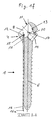
- the fastening device 30 shown in FIG Executed type of clamp each has a Screw head facing leg 31 ("lower leg”) and an opposite leg 32 ("upper leg”), the connected by an arcuate holding portion 33 with each other in which, for example, a longitudinal bar of a fixing device is determinable.
- the arranged on the lower leg 31 Extension 34 is inserted into the recess 8.
- To the embodiment is then facing the screw head Bottom 31a of the leg 31 of which the recess surrounding edge 12 in height (see Fig. 3a, b).
- the free end face 35 of the extension is in this case slightly of which the threaded bore 10 on the outside surrounding paragraph 13th spaced, resulting in a secure and defined seat of the Fastening device in the recess 8 results.
- the extension 34 has a central passage opening 36, the steplessly passes from the extension into the lower leg 31 and which is preferably cylindrical.
- the passage opening 36 is by inserting the extension in the Recess 8 centered coaxially with the threaded bore 10. Further has the screw head facing away from the leg 32 a corresponding Through opening 37, whose diameter is the same or greater than that of the lower leg.
- the passage opening 36 also serves as a guide, by means of which an imported Connecting means such as the bolt 41 fit can be brought to the threaded portion of the screw head, whereby the mounting of the fastening device substantially facilitated becomes.
- the passage opening 36 is cylindrical executed.
- the passage openings 37 and / or 36 also towards the respective insertion area expand.
- the holding portion 33 of the fastening device a midpoint M on which, through the longitudinal axis a round rod fixed in the holding area is defined, wherein the holding area center with mounted fastening device above the height of the piercing point of the recess longitudinal axis 14 by a spherical envelope of the Screw head, as shown schematically in Figure 1b is, is arranged.
- the ratio of the distance d1, the distance of the passing through the center M, on the AusappelungslCodesachse 14 perpendicular Level to the intersection of the recess longitudinal axis 14 to the Screw shaft longitudinal axis 6, to the distance d2 of the center M of the holding portion to the Ausappelungslhacksachse greater than or equal to 1.0 to 1.05, preferably greater than / equal to 1.1 to 1.25, for example, about 1.3 or greater.
- the implementation of the extension for the bolt is preferably not threaded or not with one Thread, which can interact with the bolt.
- the implementation is smooth-walled.
- the extension in carrying out the bolt and / or fixing the extension of the screw head dimensionally stable.
- the fastening device on the screw head by means of a in the Screw head engaging extension on the bone screw particularly simple manner be designed such that these in all possible debit positions of the fastening device screwed into the associated bone to the screw head is, always with the fastening device with her on the shaft assigning bottom slightly from the bone is spaced.
- the fastening device is thus practically freely rotatable about the recess longitudinal axis.
- the inventive bone screw with associated fastening device with a holding area in the recess engages the screw head, thus allowing that the fastening device in preassembled state is held securely on the screw head, that even without teeth the ball head surface always a secure hold of the fastening device is possible and that these high forces can take, even if, for example, the side member of a Spinal fixative for alignment of the corresponding spine of a patient must be deformed. Furthermore, the Bone screw implantable with minimally invasive implantation.
Landscapes
- Health & Medical Sciences (AREA)
- Orthopedic Medicine & Surgery (AREA)
- Life Sciences & Earth Sciences (AREA)
- Neurology (AREA)
- Surgery (AREA)
- Heart & Thoracic Surgery (AREA)
- Engineering & Computer Science (AREA)
- Biomedical Technology (AREA)
- Nuclear Medicine, Radiotherapy & Molecular Imaging (AREA)
- Medical Informatics (AREA)
- Molecular Biology (AREA)
- Animal Behavior & Ethology (AREA)
- General Health & Medical Sciences (AREA)
- Public Health (AREA)
- Veterinary Medicine (AREA)
- Surgical Instruments (AREA)
- Prostheses (AREA)
- Materials For Medical Uses (AREA)
Abstract
Description
Die Erfindung betrifft eine Knochenschraube zur Anbringung eines spinalen Fixiermittels, insbesondere als Pedikelschraube, mit einem in einem Knochen, insbesondere Wirbel, festlegbaren Schraubenschaft mit Gewinde zum Einschrauben in den Knochen und mit einem Schraubenkopf mit einem Befestigungsbereich für eine Befestigungseinrichtung, mittels derer das spinale Fixiermittel festlegbar ist, wobei der Befestigungsbereich einen Gewindeabschnitt zur Festlegung der Befestigungseinrichtung aufweist und wobei ferner eine Befestigungseinrichtung zur Festlegung eines spinalen Fixiermittels an der Knochenschraube umfasst ist.The invention relates to a bone screw for attachment of a Spinal fixative, especially as pedicle screw, with a fixable in a bone, in particular vertebrae Threaded screw shaft for screwing into the bone and with a screw head with a mounting area for a Fastening device, by means of which the spinal fixer can be fixed, wherein the mounting portion is a threaded portion for fixing the fastening device has and further comprising a fastening device for fixing a spinal fixation means on the bone screw is included.
Derartige Knochenschrauben sind vielfältig bekannt und können beispielsweise zur Stabilisierung oder Lagefixierung von Knochen zueinander verwendet werden, insbesondere zur Stabilisierung und Fixierung der Wirbelsäule, indem die jeweiligen Knochenschrauben in die zu fixierenden Knochen wie beispielsweise in Wirbelkörper eingeschraubt und mittels des an der zugeordneten Befestigungseinrichtung festgelegten Fixiermittels wie eines stabförmigen Längsträgers für die Osteosynthese befestigt werden.Such bone screws are widely known and can for example for the stabilization or positional fixation of bones used for each other, in particular for stabilization and fixation of the spine by removing the respective bone screws in the bones to be fixed such as screwed into the vertebral body and by means of the associated Fixing device fixed fixing such as a rod-shaped longitudinal member attached for osteosynthesis become.
Eine derartige Knochenschraube mit Befestigungseinrichtung ist aus der DE 199 44 120 A1 bekannt. Der Befestigungsbereich der Knochenschraube für die Befestigungseinrichtung ist in Form eines Kegelstumpfes gestaltet, der an einem teilkugelförmigen Schraubenkopf ausgebildet ist, wobei der sich zum Schraubenschaft hin vorzugsweise konisch erweiternde Kegelstumpf eine Gewindebohrung zur Aufnahme für eine Gewindeschraube aufweist, mittels welcher die als Klemmschelle ausgebildete Befestigungseinrichtung an dem Schraubenkopf festlegbar ist. Hierdurch soll ermöglicht werden, dass auch nach Platzierung der Knochenschraube die Lage des Längsträgers relativ zu deren Längsachse frei geändert werden kann.Such a bone screw with fastening device is known from DE 199 44 120 A1. The attachment area of the Bone screw for the fastening device is in the form of a Truncated cone shaped on a part spherical Screw head is formed, which is the screw shaft preferably conical flared truncated cone one Has threaded hole for receiving a threaded screw, by means of which designed as a clamp fastening device can be fixed to the screw head. This is intended allows that even after placement of the bone screw the position of the longitudinal member relative to its longitudinal axis can be changed freely.
Bei einer derartige Knochenschraube hat es sich jedoch als nachteilig herausgestellt, dass bei implantierter Knochenschraube aufgrund der abstehenden Kegelstümpfe eine sichere Anordnung und einfache Handhabung der Klemmschellen auf dem Kegelstumpf während der Festlegung und/oder der Ausrichtung des spinalen Fixiermittels nicht immer in der gewünschten Weise möglich ist. So ist bei dieser Anordnung die Schelle mit dem Schellenbogen, welcher der Aufnahme des Fixierstabes dient, sehr nahe an dem Dornfortsatz des Wirbelkörpers angeordnet. Ferner besteht aufgrund der vergleichsweise geringen Höhe des Kegelstumpfes bei einer Vormontierung der Schellen die Gefahr, dass diese von dem Kegelstumpf abrutschen. Des Weiteren ist es oftmals erforderlich, den Fixierstab zur Anpassung an die Solllage der Wirbelkörper zu verformen. Ein Einschieben des Verbindungsstabes in die entsprechenden Aufnahmen der Klemmschellen ist bei der bekannten Knochenschraube aufgrund der gegebenen Anordnung der Schellen jedoch teilweise recht umständlich. Andererseits ist das Anbringen des Verbindungsstabes insbesondere bei einer langstreckigen Instrumentierung über mehrere Wirbelkörper mit vormontierten Klemmschellen schwierig, da diese über die Kegelstümpfe der implantierten Knochenschrauben gehebelt werden müssen.In such a bone screw, it has, however, as disadvantageously found that when implanted bone screw due to the protruding truncated cones a secure arrangement and easy handling of the clamps on the truncated cone during the determination and / or the orientation of the Spinal fixative not always in the desired manner is possible. Thus, in this arrangement, the clamp with the Clamp arch, which serves to receive the fixation rod, arranged very close to the spinous process of the vertebral body. Furthermore, due to the comparatively low height of the Truncated cone with a pre-assembly of the clamps the danger that these slip off the truncated cone. Furthermore it is often required, the fixing rod to adapt to the desired position deform the vertebral body. An insertion of the connecting rod in the corresponding receptacles of the clamps is in the known bone screw due to the given Arrangement of the clamps, however, sometimes quite cumbersome. On the other hand, the attachment of the connecting rod is particular in a long instrumentation over several Vertebral body with pre-assembled clamps difficult because this levered over the truncated cones of the implanted bone screws Need to become.
Darüber hinaus sind aus der DE 199 21 551 und der EP 641 548 Knochenschrauben bekannt, die eine oberflächliche Verzahnung zur Fixierung der Befestigungseinrichtung in verschiedenen Winkelstellungen ermöglichen. Die Verzahnung wird hierbei zumeist großflächig an einem gewölbten Kugelkopfabschnitt oder einer Kugelschnittfläche angebracht. Die Einbringung einer derartigen Verzahnung ist jedoch vergleichsweise aufwändig und kostenintensiv. In addition, from DE 199 21 551 and EP 641 548 Bone screws known to have a superficial toothing for fixing the fastening device in different angular positions enable. The gearing is here mostly over a large area on a curved spherical head section or a Ball cut surface attached. The introduction of such Gearing is comparatively complicated and costly.
Der Erfindung liegt die Aufgabe zugrunde, eine gattungsgemäße Knochenschraube derart weiterzubilden, dass das spinale Fixiermittel vergleichsweise einfach und sicher an der Knochenschraube festlegbar ist, auch unter Berücksichtigung einer Vormontierung der Befestigungseinrichtung an der Knochenschraube, und die gegebenenfalls auch minimalinvasiv implantierbar ist.The invention is based on the object, a generic Further develop bone screw such that the spinal fixative relatively easy and safe on the bone screw can be fixed, even taking into account a pre-assembly the fastening device to the bone screw, and which may also be implanted in a minimally invasive manner.
Die Aufgabe wird erfindungsgemäß durch eine Knochenschraube
nach Anspruch 1 gelöst. Der Schraubenkopf kann eine von einem
Gewindeabschnitt verschiedene Ausnehmung mit einer Längsachse
aufweisen, die zur verschiebungssicheren Aufnahme eines Haltebereichs
der Befestigungseinrichtung lateral zur Ausnehmungslängsachse
ausgebildet ist, wobei die Ausnehmung so gestaltet
ist, dass diese einen in die Ausnehmung eingreifenden, im Wesentlichen
kongruent ausgebildeten Haltebereich der Befestigungseinrichtung
lateral verschiebungssicher aufnehmen kann,
wobei der Gewindeabschnitt sich zumindest im wesentlichen in
Längsrichtung der Ausnehmung erstreckt.The object is achieved by a bone screw
solved according to
In die Ausnehmung kann somit ein Fortsatz der Befestigungseinrichtung eingeführt werden, wodurch ein unbeabsichtigtes Abrutschen der Befestigungseinrichtung von dem Schraubenkopf auch bei schwierigen Handhabungen eines spinalen Fixiermittels wie bei einer Verbiegung desselben verhindert wird. Die Ausnehmung kann sich hierbei relativ weit in den Schraubenkopf hinein erstrecken, wodurch eine vergleichsweise große Anlagefläche der Befestigungseinrichtung an der Schraubenkopfinnenseite bereitgestellt werden kann, so dass sich auch in vormontiertem Zustand eine stabile Baugruppe ergibt und bei festgelegter Befestigungseinrichtung hohe Haltekräfte aufgenommen werden können. Ferner wird durch die erfindungsgemäße Ausbildung ermöglicht, die Außenkontur der Schraube als auch die Querschnittsgestaltungen der Ausnehmung und/oder des eingreifenden Haltebereichs unabhängig von anderen Erfordernissen an die jeweiligen Anforderungen optimal anzupassen, beispielsweise den Schraubenkopf weitestgehend als Kugelkopf auszubilden. Ferner ist die Knochenschraube mit Befestigungseinrichtung minimalinvasiv implantierbar.In the recess can thus be an extension of the fastening device be introduced, causing unintentional slipping the attachment means of the screw head also in difficult manipulations of a spinal fixative such as is prevented at a bend of the same. The recess This can be relatively far into the screw head extend, creating a comparatively large contact surface of the Attachment provided on the screw head inside can be, so even in preassembled condition a stable assembly results and fixed attachment device high holding forces can be absorbed. Furthermore, it is possible by the inventive design, the outer contour of the screw and the cross-sectional shapes the recess and / or the engaging holding portion regardless of other requirements to the respective requirements optimally adapt, for example, the screw head largely form as a ball head. Furthermore, the bone screw with minimally invasive implantable attachment device.
Durch die Erfindung wird ferner eine Befestigungseinrichtung zur Zusammenwirkung mit einer Knochenschraube bereitgestellt, wobei der Befestigungsbereich der Einrichtung einen Fortsatz aufweist, der in die Ausnehmung der Knochenschraube eingreifen kann. Weitere vorteilhafte Ausführungen der Knochenschraube ergeben sich aus den Unteransprüchen.The invention further provides a fastening device provided for cooperation with a bone screw, wherein the attachment area of the device is an extension has, which engage in the recess of the bone screw can. Further advantageous embodiments of the bone screw result from the dependent claims.
Vorzugsweise kann die Ausnehmung den Haltebereich der Befestigungseinrichtung vollumfänglich lateral verschiebungssicher aufnehmen. Vorzugsweise ist die Ausnehmung vollumfänglich geschlossen, ohne hierauf beschränkt zu sein. Ferner ist die Befestigungseinrichtung im vormontiertem Zustand vorzugsweise vollumfänglich und stufenlos gegenüber dem Schraubenschaft verdrehbar.The recess may preferably be the holding region of the fastening device fully lateral displacement safe take up. Preferably, the recess is fully closed, without being limited thereto. Furthermore, the fastening device in the preassembled state preferably fully and continuously with respect to the screw shaft rotatable.
Vorzugsweise ist die Ausnehmung des Schraubenkopf zur Aufnahme des Haltebereichs der Befestigungseinrichtung bzw. des Fortsatzes im Wesentlichen zylindrischen ausgeführt, worunter auch eine konische Ausbildung zu fassen ist, wobei der Gewindeabschnitt im Wesentlichen konzentrisch zu der Ausnehmung angeordnet ist.Preferably, the recess of the screw head for receiving the holding region of the fastening device or of the extension essentially cylindrical, including a Conical training is to take, with the threaded portion arranged substantially concentric with the recess is.
Vorteilhafterweise ist die Ausnehmung bezogen auf die Einführrichtung des Verbindungsmittels zur Festlegung der Befestigungseinrichtung dem Gewindeabschnitt vorgelagert und weist einen größeren Durchmesser auf als dieser. Hierdurch kann die Ausnehmung einen vergleichsweise großen Durchmesser aufweisen und die Ausnehmung und der Gewindeabschnitt, insbesondere wenn dieser als Gewindebohrung ausgeführt ist, können fertigungstechnisch einfach in den Schraubenkopf eingebracht werden. Ferner ist zur Festlegung der Befestigungseinrichtung zunächst lediglich das zugeordnete Verbindungsmittel in der Ausnehmung positionierbar, wodurch eine gewisse Vormontage erreicht wird, wobei erst anschließend das Verbindungsmittel an dem Gewindeabschnitt festgeschraubt wird.Advantageously, the recess is based on the insertion direction the connecting means for fixing the fastening device upstream of the threaded portion and has a larger diameter than this. This allows the Recess have a comparatively large diameter and the recess and the threaded portion, especially when this is designed as a threaded hole, manufacturing technology simply be inserted into the screw head. Further is for fixing the fastening device initially only the associated connection means in the recess positionable, whereby a certain pre-assembly is achieved only then the connecting means to the threaded portion is screwed.
Vorteilhafterweise sind die Ausnehmung und der als Gewindebohrung ausgeführte Gewindeabschnitt in Art einer Stufenbohrung ausgeführt, die lediglich durch einen Absatz voneinander getrennt sind. Vorzugsweise weist der Absatz eine senkrecht zur Ausnehmungslängsachse verlaufende Oberseite auf, woran sich unmittelbar die Gewindebohrung anschließt. Gegebenenfalls können der Gewindeabschnitt und die Ausnehmung aber auch durch einen sich in Längsrichtung der Ausnehmung erstreckenden Übergangsbereich voneinander getrennt sein.Advantageously, the recess and the threaded hole executed threaded section in the manner of a stepped bore executed, separated only by a paragraph are. Preferably, the paragraph has a perpendicular to Ausnehmungslängsachse extending top on what is immediately the threaded hole connects. If necessary, you can the threaded portion and the recess but also by a in the longitudinal direction of the recess extending transition region be separated from each other.
Vorteilhafterweise sind die Längsachsen des Gewindeabschnittes und der Ausnehmung jeweils geneigt zu der Schraubenschaftlängsachse angeordnet, und damit auch die vorzugsweise konzentrisch verlaufende Längsachse der Ausnehmung, wodurch sich eine einfache Handhabung der Knochenschraube ergibt. Der zwischen den Längsachsen von Gewindeabschnitt und Schraubenschaft eingeschlossene Winkel beträgt vorzugsweise bis zu 0°, beispielsweise ca. 30°-60° oder ca. 45°, ohne hierauf beschränkt zu sein. Gegebenenfalls kann die Gewindeabschnittslängsachse auch senkrecht zu der Schraubenschaftlängsachse angeordnet sein oder auch koaxial mit dieser.Advantageously, the longitudinal axes of the threaded portion and the recess each inclined to the screw shaft longitudinal axis arranged, and thus also preferably concentric extending longitudinal axis of the recess, resulting in a simple Handling the bone screw results. The between the Longitudinal axes of threaded section and screw shank included Angle is preferably up to 0 °, for example about 30 ° -60 ° or about 45 °, without being limited thereto. Optionally, the threaded portion longitudinal axis and vertical be arranged to the screw shank longitudinal axis or also coaxial with this.
Vorteilhafterweise verjüngt sich die Ausnehmung zum Inneren des Schraubenkopfes hin, wodurch sich der in die Ausnehmung eingesetzte Haltebereich der Befestigungseinrichtung selbst zentrieren kann und zum anderen ein Festsetzen in der Ausnehmung verhindert wird. Die Verjüngung kann konisch sein, die Wandung der Ausnehmung kann in ihrem Längsschnitt auch gebogen ausgeführt sein, wobei die Verjüngung sich mit zunehmendem Abstand zu der Einführöffnung der Ausnehmung zunehmend verjüngen kann. Advantageously, the recess tapers to the interior of the Screw head out, whereby the inserted into the recess Center the holding area of the fastening device itself can and secondly prevents settling in the recess becomes. The taper can be conical, the wall of the Recess may also be bent in its longitudinal section be, the rejuvenation with increasing distance to the Insertion opening of the recess can increasingly rejuvenate.
Es hat sich als vorteilhaft erwiesen, wenn sich die Ausnehmung konisch mit einem Winkel von 1°-20° zwischen Wandung der Ausnehmung und Ausnehmungslängsachse verjüngt, vorzugsweise ca. 2° bis ca. 10-15°, beispielsweise ca. 7,5° ohne hierauf beschränkt zu sein.It has proved to be advantageous when the recess conical with an angle of 1 ° -20 ° between the wall of the recess and recess longitudinal axis tapers, preferably about 2 ° to about 10-15 °, for example, about 7.5 ° without being limited thereto to be.
Der die Ausnehmung und den Gewindeabstand radial außen umgebende Absatz kann in etwa die gleiche radiale Erstreckung aufweisen wie der die Ausnehmung radial außen umgebende Absatz, als besonders vorteilhaft hat es sich erwiesen, wenn der den Gewindeabschnitt radial außenseitig umgebende Absatz eine größere radiale Erstreckung aufweist als der die Ausnehmung radial außen umgebende Absatz, wodurch die Ausnehmung einen vergleichsweise großen Durchmesser im Bereich der Einführöffnung für den Haltebereich der Befestigungseinrichtung aufweist.The surrounding the recess and the thread spacing radially outside Paragraph may have approximately the same radial extent as the recess radially outwardly surrounding paragraph, as it has proven to be particularly advantageous when the threaded portion radially outwardly surrounding paragraph a larger Radial extent than that of the recess radially outward surrounding paragraph, whereby the recess a comparatively large diameter in the area of the insertion opening for the Holding region of the fastening device has.
Vorzugsweise ist der Schraubenkopf auf Höhe zumindest eines Teilbereiches der Ausnehmung oder über die gesamte Höhe der Ausnehmung in Art einer Kugeloberfläche gewölbt. Hierdurch kann der Schraubenkopf im Bereich der Ausnehmung mit einer vergleichsweise großen Materialstärke bei gleichzeitig vergleichsweise großem Durchmesser der Ausnehmung ausgeführt sein, wodurch eine sehr stabile Befestigung des spinalen Fixiermittels und zugleich eine für die Einsetzung und Handhabung des Implantats günstige Geometrie des Schraubenkopfes gewährleistet ist.Preferably, the screw head is at least one height Part of the recess or over the entire height of Recess arched in the manner of a spherical surface. This can the screw head in the region of the recess with a comparatively large material thickness at the same time comparatively be made large diameter of the recess, thereby a very stable attachment of the spinal fixative and at the same time one for the insertion and handling of the implant favorable geometry of the screw head is guaranteed.
Die Ausnehmung kann einen runden oder nichtrunden, insbesondere mehreckigen Querschnitt aufweisen, wobei Anlagebereiche für den in die Ausnehmung eingreifenden Fortsatz der Befestigungseinrichtung auf einem Kreisbogen liegen können. Der mehreckige Querschnitt kann insbesondere drei- bis zwölfeckig oder mehreckig, vorzugsweise fünf- bis achteckig ausgeführt sein. Vorzugsweise sind die Querschnitte der Anlagebereiche der Ausnehmung und des in diese eingreifenden Haltebereichs der Befestigungseinrichtung, welcher mit der Wandung der Ausnehmung zur Anlage kommt, derart angepasst, dass einer der Querschnitte rund und jeweils der andere Querschnitt nichtrund mit mindestens drei umfänglich verteilten Anlagebereichen ausgeführt ist, insbesondere mehreckig ausgeführt ist. Beispielsweise können der Querschnitt der Ausnehmung oder der Querschnitt des Haltebereichs der Befestigungseinrichtung rund ausgeführt sein, wobei der Querschnitt des jeweils korrespondierenden Bauteils nichtrund, insbesondere mehreckig, ausgeführt ist. Die Mehrecke können insbesondere regelmäßige Mehrecke sein. Hierdurch wird eine erleichterte Verdrehung der Befestigungseinrichtung um die Ausnehmungslängsachse bei an der Knochenschraube vormontierter Befestigungseinrichtung ermöglicht, ohne dass die gesamten Mantelflächen der Ausnehmungswandung bzw. des Haltebereichs der Befestigungseinrichtung miteinander zur Anlage kommen, als auch ein Festsetzen der Befestigungseinrichtung bei Ausübung hoher Klemmkräfte vermieden. Es versteht sich, dass von der Mehreckigkeit mehr oder weniger große Abweichungen möglich sind, beispielsweise in Form von abgerundeten Übergangsbereichen an den Ecken und/oder abgerundeten Zwischenbereichen, die zwischen den Anlagebereichen angeordnet sind. Die Anlagebereiche können somit linienförmig oder flächig ausgeführt sein.The recess may be a round or not round, in particular Have polygonal cross-section, with investment areas for the in the recess engaging extension of the fastening device can lie on a circular arc. The polygonal Cross section may in particular be three- to twelve-sided or polygonal, preferably be executed five to octagonal. Preferably are the cross sections of the contact areas of the recess and the engaging portion of the fastening means engaged therein, which with the wall of the recess for Plant comes, adapted so that one of the cross sections round and in each case the other cross-section non-circular with at least three circumferentially distributed investment areas is executed, is executed in particular polygonal. For example, you can the cross section of the recess or the cross section of the holding area be carried out around the fastening device, wherein the cross section of the respective corresponding component non-circular, in particular polygonal, is executed. The mehrecke in particular may be regular multi-course. This will a facilitated rotation of the fastening device to the Recessed longitudinal axis premounted at the bone screw Fastening device allows, without the entire lateral surfaces the recess wall or the holding area of the Fastener come to rest with each other, as well a setting of the fastening device when exercising high Clamping forces avoided. It is understood that from the polygraph more or less large deviations are possible for example, in the form of rounded transition areas the corners and / or rounded intermediate areas between the investment areas are arranged. The investment areas can thus be executed linear or flat.
Vorzugsweise erstreckt sich die Innenwandung der Ausnehmung in der Höhe auf der dem Schraubenschaft nächstbenachbarten Seite der Ausnehmung bis über die Verlängerung der Mantelfläche des Schraubenschaftes hinaus in den Schraubenkopf hinein. Die dem Schraubenschaft nächstbenachbarte Seite der Ausnehmung ergibt sich hierbei durch eine Ebene, die von der Ausnehmungslängsachse und der Schraubenschaftlängsachse aufgespannt wird, und durch die Neigungsrichtung der Ausnehmungslängsachse bestimmt wird. Die Mantelfläche des Schraubenschaftes kann die Einhüllende des Gewindeabschnitts oder die Einhüllende des Schaftbereichs, der durch die jeweilige Basis der Gewindeabschnitte bestimmt wird, definiert sein. Hierdurch kann die Ausnehmung eine große Tiefe aufweisen, ohne die Geometrie der Schraubenkopfoberfläche zu beeinflussen, die unabhängig von der Ausgestaltung der Ausnehmung oder deren Tiefe in geeigneter Weise gestaltet werden kann.Preferably, the inner wall of the recess extends in the height on the side closest to the screw shaft the recess until over the extension of the lateral surface of the Screw shank out into the screw head. The the Screw shaft next adjacent side of the recess results in this case by a plane that of the recess longitudinal axis and the screw shank longitudinal axis is clamped, and determined by the direction of inclination of the recess longitudinal axis becomes. The lateral surface of the screw shaft can the envelope the threaded portion or the envelope of the shaft portion, determined by the respective base of the threaded sections will be defined. This allows the recess a have great depth, without the geometry of the screw head surface to influence, regardless of the design the recess or its depth designed in a suitable manner can be.
Vorzugsweise erstreckt sich die Ausnehmung derart in den Schraubenkopf hinein, dass der die Tiefe der Ausnehmung begrenzende Querschnitt bzw. der Boden der Ausnehmung in etwa auf Höhe oder auf der der Öffnung der Ausnehmung abgewandten Seite des Schnittpunktes von Schraubenschaftlängsachse und Ausnehmungslängsachse angeordnet ist. Der Boden der Ausnehmung kann hierbei durch den unteren Umfangsrand der Ausnehmung definiert werden, der Ausnehmungsboden kann selbstverständlich eine Öffnung aufweisen, an welche sich beispielsweise eine Gewindebohrung anschließen kann. Der oben definierte Schnittpunkt entspricht bei im Wesentlichen kugelförmiger Gestaltung des Schraubenkopfes dem Kugelmittelpunkt. Durch diese große Tiefe der Ausnehmung kann eine sehr sichere und stabile Vormontierung der Befestigungseinrichtung erfolgen und auch bei großen Haltekräften wird eine nur vergleichsweise geringe Flächenpressung der miteinander zur Anlage kommenden Anlagebereiche des Haltebereichs der Befestigungseinrichtung mit der Innenwandung der Ausnehmung erzielt.Preferably, the recess extends in such a way Screw head into that of the depth of the recess bounding Cross section or the bottom of the recess approximately at height or on the side facing away from the opening of the recess the intersection of screw shank longitudinal axis and recess longitudinal axis is arranged. The bottom of the recess can in this case defined by the lower peripheral edge of the recess Of course, the recess floor can of course be an opening have, to which, for example, a threaded hole can connect. The above defined intersection corresponds with a substantially spherical design of the Screw head the ball center. Through this great depth The recess can be a very safe and stable pre-assembly the fastening device and even with large holding forces is only a comparatively low surface pressure the abutting contact areas of the holding area with each other the fastening device with the inner wall of the Recess achieved.
Vorzugsweise ist der Schraubenkopf im Wesentlichen als Kugelkopf oder Teilkugelkopf ausgeführt, wobei der Kugelkopf vorzugsweise bis auf seitliche, einander gegenüberliegende Abplattungen und sonstigen Haltebereichen zur Befestigung von Einrichtungen, die für das jeweilige Implantat von Bedeutung sind, wie von Verlängerungsstäben oder dergleichen, kugelförmig ausgeführt ist. Die kugelkopfförmige Gestaltung erstreckt sich vorzugsweise auch über einen Teil der Höhe oder die gesamte Höhe der Ausnehmung.Preferably, the screw head is essentially a ball head or partial ball head, wherein the ball head is preferably except for lateral, opposing flattenings and other holding areas for fixing facilities, which are important for the respective implant, as of extension bars or the like, spherical is. The ball-shaped design extends preferably also over part of the height or the entire height the recess.
Vorzugsweise ist die Ausnehmung, an welche sich ein Gewindeabschnitt in Form einer Gewindebohrung anschließen kann, als Durchtrittsöffnung durch den Schraubenkopf ausgebildet.Preferably, the recess to which a threaded portion in the form of a threaded hole can connect as Passage opening formed by the screw head.
Die erfindungsgemäße Befestigungseinrichtung, welche der Festlegung eines spinalen Fixiermittels an einer Knochenschraube, insbesondere einer oben beschriebenen Knochenschraube, dient, weist einen im wesentlichen zylindrischen Fortsatz zur Einführung in eine Ausnehmung einer korrespondierenden Knochenschraube auf, wobei der Fortsatz eine Durchtrittsöffnung für ein Verbindungselement zur Festlegung der Befestigungseinrichtung an dem Schraubenkopf aufweist. Ein derartiges Verbindungselement kann insbesondere als Schraubbolzen ausgeführt sein. Unter einer im Wesentlichen zylindrischen Gestalt des Fortsatzes sei auch eine weiter unten beschriebene mehreckige Gestalt oder andere nichtrunde Gestalt verstanden, bei welcher der Fortsatz an einer Innenwandung einer Ausnehmung anlegbare Anlageflächen aufweist, die auf einem Kreisbogen liegen. Ferner soll die im wesentlichen zylindrische Ausgestaltung auch eine konische oder eine andere rotationssymmetrische Form der Fortsatzes bzw. einer Einhüllenden desselben mit umfassen.The fastening device according to the invention, which the determination a spinal fixative on a bone screw, in particular a bone screw described above, is used, has a substantially cylindrical extension for insertion in a recess of a corresponding bone screw on, wherein the extension has a passage opening for a connecting element for fixing the fastening device having the screw head. Such a connection element can be designed in particular as a screw bolt. Under one be substantially cylindrical shape of the extension also a polygonal shape described below or others understood non-round shape, in which the extension to an inner wall of a recess engageable contact surfaces has, which lie on a circular arc. Furthermore, in the essential cylindrical design also a conical or another rotationally symmetrical shape of the extension or one Envelopes of the same include.
Vorzugsweise weist die Befestigungseinrichtung einen dem Schraubenschaft zugewandten und einen abgewandten Schenkel auf, zwischen denen ein spinales Fixiermittel festlegbar ist. Es sind aber auch andere Ausgestaltungen der Befestigungseinrichtung möglich. Die Schenkel können einstückig aneinander angeformt sein, beispielsweise in Art einer Klemmschelle, die Schenkel können jedoch auch lösbar aneinander befestigbar sein. Vorzugsweise ist an dem dem Schraubenschaft zugewandten Schenkel der in der Ausnehmung positionierbare Fortsatz des Haltebereichs der Befestigungseinrichtung angeordnet. Gegebenenfalls kann jedoch der Fortsatz auch an dem dem Schraubenschaft abgewandten Schenkel angeordnet sein, welcher den benachbarten Schenkel durchgreift, um in die Ausnehmung einzugreifen. Die Befestigungseinrichtung wird hierbei vorzugsweise durch das gleiche Feststellmittel an dem Schraubenkopf befestigt, welches auch der Festlegung des spinalen Fixiermittels dient, gegebenenfalls können aber auch zwei unabhängige Feststellmittel wie Schraubbolzen vorgesehen sein. Preferably, the fastening device has a the Screw shaft facing and an opposite leg, between which a spinal fixative can be fixed. It but are also other embodiments of the fastening device possible. The legs can be formed integrally with each other be, for example in the manner of a clamp, the However, legs can also be detachably fastened to each other. Preferably, on the leg facing the screw shaft the positionable in the recess extension of the holding area arranged the fastening device. Possibly However, the extension can also be facing away from the screw shaft Leg be arranged, which the adjacent Passes through leg to engage in the recess. The Fastening device is in this case preferably by the same locking means attached to the screw head, which also serves to fix the spinal fixative, if necessary but can also be two independent detection means such as Be provided bolt.
Vorzugsweise liegt der Haltebereich der Befestigungseinrichtung nur im Bereich der Mantelfläche des Fortsatzes an der Kugelkopfschraube an, gegebenenfalls kann auch zusätzlich der die Ausnehmung außenseitig umgebenden umlaufenden Rand des Schraubenkopfes, welcher einen Oberflächenbereich des Schraubenkopfes darstellen kann eine Anlagefläche für den die Befestigungseinrichtung bilden und/oder der dem freien Ende des Fortsatzes gegenüberliegende Bereich der Ausnehmung wie ein zwischen der gewindefreien Ausnehmung und dem Gewindeabschnitt vorgesehener Absatz. Gegebenenfalls kann auch der dem Schraubenkopf zugewandte Schenkel der Befestigungseinrichtung an der Schraubenkopfoberfläche anliegen, beispielsweise an einem Verbindungsbereich des Schenkels mit dem Fortsatz oder über einen darüber hinausgehenden Umfangsbereich, beispielsweise auch vollumfänglich.Preferably, the holding region of the fastening device is located only in the region of the lateral surface of the extension of the ball screw If necessary, in addition to the Recess on the outside surrounding circumferential edge of the screw head, which is a surface area of the screw head can represent a contact surface for the fastening device form and / or opposite the free end of the extension Area of the recess like one between the unthreaded Recess and the threaded portion provided Paragraph. Optionally, also facing the screw head Leg of the fastening device on the screw head surface abutment, for example at a connection area of the thigh with the extension or over one above it outgoing peripheral area, for example, also fully.
Der Fortsatz kann einen runden oder mehreckigen Außenquerschnitt aufweisen, wobei in letzterem Falle die Ausnehmung vorzugsweise einen runden Querschnitt aufweist. Allgemein können der Fortsatz und die Ausnehmung derart ausgeführt, dass der Fortsatz nur mit einem Teil seiner in der Ausnehmung angeordneten Mantelfläche an der Innenwandung der Ausnehmung anliegt. Der Fortsatz kann hierbei drei- bis zwölfeckig oder mehreckig ausgeführt sein, vorzugsweise fünf- bis achteckig. Vorzugsweise ist das Vieleck jeweils gleichseitig, was auch für eine vieleckige Ausgestaltung der Ausnehmung gelten kann. Es versteht sich, dass auch bei einer mehreckigen Ausgestaltung des Fortsatzes bzw. der Ausnehmung diese mehr oder weniger von der Idealform abweichen kann und an den Übergangsbereichen zwischen verschiedenen Flächen Abrundungen vorgesehen sein können oder die Flächen selber eine geringfügige Wölbung, vorzugsweise konkave Wölbung, aufweisen.The extension can be a round or polygonal outer cross section have, in the latter case, the recess preferably has a round cross-section. General can the extension and the recess designed such that the Extension only with a part of it arranged in the recess Mantle surface rests against the inner wall of the recess. The extension can be three- to twelve-sided or polygonal be executed, preferably five to octagonal. Preferably the polygon is always equilateral, which is also a polygonal one Design of the recess may apply. It understands itself, that even with a polygonal configuration of the extension or the recess this more or less of the ideal shape may differ and at the transition areas between different surfaces rounding can be provided or the surfaces themselves a slight curvature, preferably concave Vaulting, exhibit.
Die Anlagebereiche der Ausnehmung oder des Fortsatzes können als leistenartige, sich in Fortsatzlängsrichtung bzw. Ausnehmungslängsrichtung erstreckende Bereiche ausgeführt sein, die mit dem korrespondierenden Anlagebereich des jeweils korrespondierenden Bauteils linienförmig oder flächig zur Anlage bringbar sind. Die leistenartigen Bereiche können insbesondere in den Übergangsbereichen von Außenflächen des Fortsatzes angeordnet sein, die von einem runden Querschnitt stärker abweichen, beispielsweise in dem Übergangsbereich von ebenen Mantelflächen des Fortsatzes bzw. der Ausnehmung. Die leistenartigen Bereiche sind jeweils vorzugsweise gleichmäßig um den Umfang des Fortsatzes oder der Ausnehmung verteilt angeordnet. Die leistenartigen Bereiche können sich um den Umfang des Fortsatzes bzw. der Ausnehmung um weniger als 10°, vorzugsweise weniger als 5° oder um ca. 2° oder weniger erstrecken. Die leistenartigen Bereiche können selber eine im Wesentlichen kreisrunde Außenkontur aufweisen oder aber in Form von im Wesentlichen ebenen Abkantungen von Mantelflächenbereichen des Fortsatzes oder der Ausnehmung bestehen, so dass im Wesentlichen zwei geringfügig beabstandete linienförmige Anlagebereiche bereitgestellt werden, die sich in Längsrichtung der Ausnehmung oder der Fortsatzes erstrecken.The contact areas of the recess or the extension can as strip-like, in the extension longitudinal direction or recess longitudinal direction extending areas to be executed, the with the corresponding investment area of the corresponding one Component line or surface can be brought to the plant are. The strip-like areas can be found in particular in arranged the transition regions of outer surfaces of the extension which deviate more strongly from a round cross-section, For example, in the transition region of flat lateral surfaces of the extension or the recess. The strip-like areas are each preferably evenly around the circumference of the extension or the recess arranged distributed. The strip-like Areas can be around the circumference of the extension or the recess by less than 10 °, preferably less than 5 ° or extend by about 2 ° or less. The strip-like areas can themselves have a substantially circular outer contour or in the form of substantially flat bends of lateral surface areas of the extension or the Recess so that essentially two slightly be provided spaced line-shaped investment areas, in the longitudinal direction of the recess or the extension extend.
Der dem Fortsatz abgewandte Schenkel der Befestigungseinrichtung kann eine Durchtrittsöffnung zur Durchführung eines Festlegungsmittels der Befestigungseinrichtung an einer korrespondierenden Knochenschraube aufweisen.The projection facing away from the leg of the fastening device may be a passage opening for performing a fixing agent the fastening device to a corresponding Have bone screw.
Vorzugsweise ist der Mittelpunkt eines Haltebereichs zur Festlegung des spinalen Fixiermittels, wie etwa eines Längsstabes einer Fixiereinrichtung, in etwa auf Höhe der außenseitigen Öffnungsmündung der Ausnehmung oder oberhalb derselben, wie beispielsweise auf Höhe oder oberhalb des Durchstoßpunktes der Ausnehmungslängsachse durch die kugelförmige Einhüllende der Schraubenkopfoberfläche angeordnet. Der Haltebereichmittelpunkt kann in der Höhe in Ausnehmungslängsrichtung um größer/gleich den 1,1 bis 1,2-fachen oder größer/gleich den 1,5-fachen oder 1,75-fachen Kugelkopfradius von dem Kugelkopfmittelpunkt bzw. dem Schnittpunkt der Schraubenschaftlängsachse mit der Ausnehmungslängsachse angeordnet sein.Preferably, the center of a holding area is for fixing of the spinal fixer, such as a longitudinal bar a fixing device, approximately at the level of the outside Opening orifice of the recess or above the same, as for example, at or above the puncture point of the Ausnehmungslängsachse through the spherical envelope of the Screw head surface arranged. The holding area center may be greater in height in recess longitudinal direction 1.1 to 1.2 times or greater / equal to 1.5 times or 1.75 times the ball head radius from the ball center or the intersection of the screw shaft longitudinal axis with the Ausnehmungslängsachse be arranged.
Der untere Schenkel der Befestigungseinrichtung kann auf einer Kugelabschnittsfläche des Schraubenkopfes aufliegen oder oberhalb dieser abgeordnet sein.The lower leg of the fastening device can on a Ball section surface of the screw head rest or above this be seconded.
Vorzugsweise ist die Knochenschraube mit zugeordneter und an dieser bestimmungsgemäß festgelegter Befestigungseinrichtung derart ausgebildet, dass in sämtlichen möglichen Sollstellungen der Befestigungseinrichtung die Knochenschraube bis zum Schraubenkopf in einen Knochen, insbesondere Wirbel, eindrehbar ist. Dies gilt insbesondere für eine Sollstellung, in welcher der Haltebereich der Befestigungseinrichtung für ein spinales Fixiermittel einen geringstmöglichen Abstand zu dem dem Schraubenkopf abgewandten Ende des Schraubenschaftes aufweist bzw. sich in der durch die Aufnahmelängsrichtung und die Schraubenschaftlängsrichtung aufgespannten Ebene in der dem Schraubenschaft zugewandten Stellung befindet.Preferably, the bone screw is associated with and on this intended fixed attachment device designed such that in all possible debit positions the fastening device, the bone screw to the screw head in a bone, in particular vertebra, is screwed. This is especially true for a debit position in which the Holding area of the fastening device for a spinal fixative a minimum possible distance to the screw head has opposite end of the screw shaft or in the longitudinal direction of the receptacle and the screw shaft longitudinal direction clamped plane in the screw shaft facing position.
In nicht festgelegtem Zustand kann der Fortsatz gegenüber dem Schraubenkopf um die Ausnehmungslängsachse zumindest um einen Teilumfang wie beispielsweise um 90° oder mehr oder um 180° oder mehr, oder vollumfänglich verdrehbar, insbesondere frei verdrehbar, sein.In an unfixed state, the extension opposite to the Screw head around the recess longitudinal axis at least one Partial circumference such as 90 ° or more or 180 ° or more, or completely rotatable, especially free be rotatable.
Vorzugsweise ist eine Knochenschraube mit zugeordneter Befestigungseinrichtung mit einer Führung versehen, mittels welcher ein Verbindungsmittel wie beispielsweise ein Schraubbolzen zur Festlegung der Befestigungseinrichtung an dem Schraubenkopf durch die Befestigungseinrichtung passgenau an den zugeordneten Gewindeabschnitt des Schraubenkopfes heranführbar ist. Die Anordnung und Festlegung des Verbindungsmittels an dem Schraubenkopf wird hierdurch erleichtert. Diese Führung kann durch den dem Schraubenkopf zugewandten und/oder abgewandten Schenkel, durch den Fortsatz der Befestigungseinrichtung und/oder durch einen anderen geeigneten Bereich der Knochenschraube und/oder der Befestigungseinrichtung bereitgestellt werden. Insbesondere kann eine Durchtrittsöffnung des Fortsatzes vorgesehen sein, die konzentrisch zu dem als Gewindebohrung ausgeführten Gewindeabschnitt ausgeführt ist und unter Berücksichtigung des Gewindes in etwa den gleichen Innendurchmesser aufweist wie die Gewindebohrung.Preferably, a bone screw with associated fastening device provided with a guide, by means of which a connecting means such as a bolt for Fixing the fastening device to the screw head by the fastening device accurately to the assigned Threaded portion of the screw head is approachable. The order and fixing the connecting means to the screw head is thereby facilitated. This guide can by the the screw head facing and / or facing away leg, through the extension of the fastening device and / or by another suitable area of the bone screw and / or the fastening device are provided. Especially a passage opening of the extension can be provided, concentric with the threaded portion designed as a threaded bore is executed and considering the thread has approximately the same inner diameter as the Threaded hole.
Die Erfindung sei nachfolgend beispielhaft beschrieben und anhand der Figuren beispielhaft erläutert. Es zeigen:
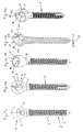
Figur 1- eine Darstellung einer erfindungsgemäßen Knochenschraube in einer Ansicht von hinten (Fig. 1a), eine Seitenansicht (Fig. 1b), eine Frontansicht (Fig.1c), einen Schnitt A-A gemäß Figur 1b (Fig. 1d,f) und eine perspektivische Ansicht (Fig. 1e),
Figur 2- eine Befestigungseinrichtung für eine Knochenschraube gemäß Figur 1 in perspektivischer Darstellung (Figur 2a), in Draufsicht (Fig. 2b), in Seitenansicht (Fig. 2c), in Ansicht von unten (Fig. 2d), entlang eines Schnittes A-A gemäß Figur 2b (Fig. 2e) und in einer alternativen Ausführungsform (Fig. 2f).
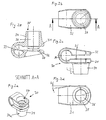
Figur 3- eine Knochenschraube gemäß Fig. 1 (teilweise im Ausschnitt) und eine Befestigungseinrichtung gemäß Fig. 2 in verschiedenen Ansichten.
- FIG. 1
- 1 a), a front view (FIG. 1 b), a section AA according to FIG. 1 b (FIGS. 1 d, f) and a perspective view (FIG. Fig. 1e),
- FIG. 2
- 2 shows a fastening device for a bone screw according to FIG. 1 in a perspective view (FIG. 2 a), in a side view (FIG. 2 c), in a view from below (FIG. 2 d), along a section AA according to FIG. Fig. 2e) and in an alternative embodiment (Fig. 2f).
- FIG. 3
- a bone screw according to FIG. 1 (partially in section) and a fastening device according to FIG. 2 in different views.
Die Knochenschraube 1 gemäß Figur 1 dient der Anbringung eines
spinalen Fixiermittels wie eines Längsstabes und kann insbesondere
als Pedikelschraube verwendet werden. Die Knochenschraube
kann mit dem mit einem Gewinde 2 versehenen Schraubenschaft 3
in einen Wirbel oder einen anderen Knochen eingeschraubt werden.
Der Schraubenkopf 4 ist im Wesentlichen als Kugelkopf ausgeführt,
der seitliche Abflachungen 5 aufweist, die mit Haltebereichen
für einen nicht dargestellten Verbindungsstab in Form
von parallel zur Schaftlängsachse verlaufenden Nuten 7 versehen
sind, in welche in bekannter Weise entsprechende Fortsätze des
Verbindungsstabes eingreifen können. Ferner ist an der einer
Ausnehmung 8 abgewandten Rückseite des Schraubenkopfes ein Haltebereich
in Form einer sich quer zur Schaftlängsachse erstreckenden
Nut 9 eingebracht, die der Ankoppelung eines alternativ
ausgeführten Verbindungsstabes oder einer anderen Einrichtung
zur Verwendung mit der erfindungsgemäßen Knochenschraube dient.The
Die im Wesentlichen oder exakt zylindrische und vorzugsweise
gewindefreie Ausnehmung 8 dient der Aufnahme eines als Fortsatz
34 ausgebildeten Haltebereichs der in Figur 2 dargestellten Befestigungseinrichtung
30, wobei die Befestigungseinrichtung im
nicht festgelegten Zustand frei um die Ausnehmungslängsachse
verdrehbar ist. Der im wesentlichen zylindrische Fortsatz wird
hierbei seitlich spielfrei und verkippsicher in der Ausnehmung
gehaltert. Zur verdrehfesten Festlegung der Befestigungseinrichtung
30 an der Knochenschraube 1 dient ein als Gewindebohrung
10 ausgebildeter Gewindeabschnitt, der einen korrespondierenden
Schraubbolzen 41 aufnehmen kann, mittels dessen zugleich
der zugeordnete Bestandteil des spinalen Fixiermittels an der
Knochenschraube festlegbar ist. Der Schraubbolzen weist hierbei
zwischen Schraubenkopf und Gewinde eine umlaufende Nut 42 auf,
die zumindest bereichsweise auf Höhe des Spaltes zwischen den
beiden Schenkeln der Befestigungseinrichtung abgeordnet ist,
nach dem Ausführungsbeispiel befindet sich der Nutgrund auf Höhe
der Oberseite des dem Schraubenkopf zugewandten Schenkels.
Die Gewindebohrung 10 ist hierbei konzentrisch zu der zylindrischen
Ausnehmung 8 angeordnet. Die vorzugsweise gewindefreie
Ausnehmung 8 ist hierbei der Schraubenkopfoberseite zugewandt,
der Gewindeabschnitt ist in Einführrichtung des Verbindungsmittels
nachgelagert bzw. auf der der Einführöffnung 11 der Ausnehmung
abgewandten Seite angeordnet. Die Ausnehmung 8 weist
über ihre gesamte Tiefe einen größeren Durchmesser auf, als die
Gewindebohrung 10. Ausnehmung 8 und Gewindebohrung 10 sind in
Art einer Stufenbohrung ausgeführt, wobei diese jeweils an ihrem
der Einführöffnung 11 zugewandten Ende durch einen Rand 12
bzw. Absatz 13 außenseitig umgeben werden. Der Rand 12 liegt
hierbei in einer Kugelabschnittsebene, welche den kugelförmigen
Schraubenkopf abkappt. Der den Gewindeabschnitt radial außenseitig
umgebende Absatz 13 weist eine größere radiale Erstreckung
auf als der die Ausnehmung radial außen umgebende Absatz
bzw. Rand 12.The substantially or exactly cylindrical and preferably
unthreaded
Die Ausnehmung 8 ist nach dem Ausführungsbeispiel konisch ausgeführt
und verjüngt sich zu dem Schraubenkopfmittelpunkt hin.
Die Neigung der Innenwandung der Ausnehmung und die Neigung der
korrespondierenden Anlageflächen des Fortsatzes entsprechen
einander, die Neigung zur Ausnehmungslängsachse beträgt ca. 7°.
Der Winkel zwischen der Längsachse 14 der Ausnehmung 8 bzw. des
konzentrisch angeordneten Gewindeabschnittes mit der Schraubenschaftlängsachse
6 beträgt ca. 45°.The
Die Ausnehmung weist gemäß dem Ausführungsbeispiel einen runden
Querschnitt auf, die mit der Innenwandung 15 der Ausnehmung zur
Anlage kommende Mantelfläche 34a des Fortsatz 34 ist nach Fig.
2a rotationssymmetrisch bzw. konisch mit gleichem Konuswinkel
ausgeführt, so Fortsatz und Ausnehmungswandung vollumfänglich
flächig aneinander anlegbar sind. Gemäss der weiteren Ausführungsform
nach Fig. 2e weist der im wesentlichen zylindrische
Fortsatz 34 einen mehreckigen, sich auf das freie Ende verjüngenden
Querschnitt auf. Hierdurch werden leistenförmige Anlagebereiche
39 geschaffen, die jeweils zwischen zurückspringenden,
vorzugsweise ebenen Bereichen 38 angeordnet sind und sich in
Längsrichtung des Fortsatzes bzw. bei montierter Befestigungseinrichtung
im Wesentlichen in Längsrichtung der Ausnehmung
erstrecken. Die leistenartigen Anlagebereiche 39 können linienförmig
oder flächig mit einem Umfangsbereich an der Ausnehmungsinnenwandung
15 anliegen. Die umfängliche Winkelerstreckung
eines jeden der leistenartigen Anlagebereiche 39 kann
z.B. ca. 5° betragen, ohne hierauf beschränkt zu sein. Durch
die leistenförmigen Anlagenbereiche kann ein Festsetzen der
Bauteile aneinander bei Ausübung hoher Anpresskräfte vermieden
werden. Die leistenförmigen Anlagebereiche 39 erstrecken sich
hierbei über die gesamte Höhe des Fortsatzes 34, ohne dass dies
zwingend notwendig ist.The recess has a round according to the embodiment
Cross-section, with the
Gemäß Figur 1f erstreckt sich auf der dem Schraubenschaft
nächst benachbarten Seite der Ausnehmung 8, welche in der durch
die Ausnehmungslängsachse 14 und der Schraubenschaftlängsachse
6 aufgespannten Ebene liegt, die Innenwandung 15 der Ausnehmung
in ihrer Höhe bis über die Verlängerung der Mantelfläche 16 des
Schraubenschaftes hinaus in den Schraubenkopf hinein. Die Mantelfläche
ist hierbei die Einhüllende des Schraubenschaftes
einschließlich Gewinde, gegebenenfalls kann sich dies jedoch
auch auf die Mantelfläche des Schraubenschaftes bezogen auf die
Basis der jeweiligen Gewindegänge beziehen (Mantelfläche 16a).
Die Ausnehmung kann sich so sehr weit und unabhängig von der
Gestaltung der Außenoberfläche des Schraubenkopfes in diesen
erstrecken.According to Figure 1f extends on the screw shaft
next adjacent side of the
Der die Tiefe der gewindefreien Ausnehmung begrenzende Querschnittsbereich,
der hier durch den Absatz 13 bzw. Boden der
Ausnehmung gebildet wird, ist bezogen auf die Ausnehmungslängsachse
auf der der Öffnung der Ausnehmung abgewandten Seite des
Schnittpunktes der Schraubenlängsachse mit der Ausnehmungslängsachse
oder auch auf Höhe des Schnittpunktes angeordnet.
Dies kann entsprechend auch für das freie Ende des in der Ausnehmung
angeordneten Fortsatzes bei festgelegter Befestigungseinrichtung
gelten, das aber von dem Boden der Ausnehmung auch
beabstandet sein kann. Das Ende der gewindefreien Ausnehmung
ist somit auf der der Einführöffnung 11 der Ausnehmung abgewandten
Seite des geometrischen Mittelpunktes 17 des Schraubenkopfes
angeordnet. Die Ausnehmung 8 und Gewindebohrung 10 sind
nach dem Ausführungsbeispiel als Stufenbohrung mit Durchtrittsöffnung
18 ausgeführt, wodurch sich fertigungstechnische Vorteile
ergeben.The depth of the unthreaded recess limiting cross-sectional area,
here by
Die in Figur 2 dargestellte Befestigungseinrichtung 30 ist in
Art einer Klemmschelle ausgeführt und weist jeweils einen dem
Schraubenkopf zugewandten Schenkel 31 ("unterer Schenkel") und
einen abgewandten Schenkel 32 ("oberer Schenkel") auf, die
durch einen bogenförmigen Haltebereich 33 miteinander verbunden
sind, in welchem beispielsweise ein Längsstab einer Fixiereinrichtung
festlegbar ist. Der an dem unteren Schenkel 31 angeordnete
Fortsatz 34 ist in die Ausnehmung 8 einführbar. Nach
dem Ausführungsbeispiel ist dann die dem Schraubenkopf zugewandte
Unterseite 31a des Schenkels 31 von dem die Ausnehmung
umgebenden Rand 12 in der Höhe beabstandet (siehe Fig. 3a,b).
Die freie Stirnseite 35 des Fortsatzes ist hierbei geringfügig
von dem die Gewindebohrung 10 außenseitig umgebenden Absatz 13
beabstandet, wodurch sich ein sicherer und definierter Sitz der
Befestigungseinrichtung in der Ausnehmung 8 ergibt. Der Fortsatz
34 weist eine zentrische Durchtrittsöffnung 36 auf, die
stufenlos von dem Fortsatz in den unteren Schenkel 31 übergeht
und die vorzugsweise zylinderförmig ausgeführt ist. Die Durchtrittsöffnung
36 wird durch Einsetzen des Fortsatzes in die
Ausnehmung 8 koaxial zu der Gewindebohrung 10 zentriert. Ferner
weist der dem Schraubenkopf abgewandte Schenkel 32 eine entsprechende
Durchtrittsöffnung 37 auf, deren Durchmesser gleich
oder größer als der des unteren Schenkels ist. Die Durchtrittsöffnung
36 dient zugleich als Führung, mittels welcher ein eingeführtes
Verbindungsmittel wie der Schraubbolzen 41 passgenau
an den Gewindeabschnitt des Schraubenkopfes heranführbar ist,
wodurch die Montage der Befestigungseinrichtung wesentlich erleichtert
wird. Die Durchtrittsöffnung 36 ist zylinderförmig
ausgeführt. Gegebenenfalls können die Durchtrittsöffnungen 37
und/oder 36 sich auch in Richtung auf den jeweiligen Einführbereich
hin erweitern.The
Gemäß Figur 3b weist der Haltebereich 33 der Befestigungseinrichtung
einen Mittelpunkt M auf, welcher durch die Längsachse
eines in dem Haltebereich fixierten Rundstabes definiert wird,
wobei der Haltebereichmittelpunkt bei montierter Befestigungseinrichtung
oberhalb der Höhe des Durchstoßpunktes der Ausnehmungslängsachse
14 durch eine kugelförmige Einhüllende des
Schraubenkopfes, wie sie in der Figur 1b schematisch dargestellt
ist, angeordnet ist. Hierdurch ergeben sich bei der Ausrichtung
des Längsstabes eines spinalen Fixiermittels sowie bei
dessen Befestigung besondere Vorteile. Das Verhältnis des Abstandes
d1, der der Abstand der durch den Mittelpunkt M verlaufenden,
auf der Ausnehmungslängsachse 14 senkrecht stehenden
Ebene zu dem Schnittpunkt der Ausnehmungslängsachse 14 zu der
Schraubenschaftlängsachse 6 ist, zu dem Abstand d2 des Mittelpunktes
M des Haltebereichs zu der Ausnehmungslängsachse beträgt
größer/gleich 1,0 bis 1,05, vorzugsweise größer/gleich
1,1 bis 1,25, beispielsweise ca. 1,3 oder größer.According to Figure 3b, the holding
Die Durchführung des Fortsatzes für den Schraubbolzen ist vorzugsweise nicht mit einem Gewinde versehen oder nicht mit einem Gewinde, welches mit dem Schraubbolzen zusammenwirken kann. Vorzugsweise ist die Durchführung glattwandig. Vorzugsweise ist der Fortsatz bei Durchführung des Schraubbolzens und/oder Festlegung des Fortsatzes an dem Schraubenkopf formstabil.The implementation of the extension for the bolt is preferably not threaded or not with one Thread, which can interact with the bolt. Preferably, the implementation is smooth-walled. Preferably the extension in carrying out the bolt and / or fixing the extension of the screw head dimensionally stable.
Ferner kann bei der erfindungsgemäßen Anordnung der Befestigungseinrichtung an dem Schraubenkopf mittels eines in den Schraubenkopf eingreifenden Fortsatzes die Knochenschraube auf besonders einfache Weise derart ausgebildet werden, dass diese bei sämtlichen möglichen Sollstellungen der Befestigungseinrichtung bis zum Schraubenkopf in den zugeordneten Knochen eindrehbar ist, wobei stets die Befestigungseinrichtung mit ihrer auf den Schaft zuweisenden Unterseite geringfügig von dem Knochen beabstandet ist. Die Befestigungseinrichtung ist somit praktisch frei um die Ausnehmungslängsachse verdrehbar.Furthermore, in the inventive arrangement of the fastening device on the screw head by means of a in the Screw head engaging extension on the bone screw particularly simple manner be designed such that these in all possible debit positions of the fastening device screwed into the associated bone to the screw head is, always with the fastening device with her on the shaft assigning bottom slightly from the bone is spaced. The fastening device is thus practically freely rotatable about the recess longitudinal axis.
Durch die erfindungsgemäße Knochenschraube mit zugeordneter Befestigungseinrichtung, die mit einem Haltebereich in die Ausnehmung des Schraubenkopfes eingreift, wird somit ermöglicht, dass die Befestigungseinrichtung auch in vormontiertem Zustand sicher an dem Schraubenkopf gehaltert ist, dass auch ohne Verzahnung der Kugelkopfoberfläche stets ein sicherer Halt der Befestigungseinrichtung ermöglicht ist und dass diese hohe Kräfte aufnehmen kann, auch wenn beispielsweise der Längsträger eines spinalen Fixiermittels zur Ausrichtung der entsprechenden Wirbelsäule eines Patienten deformiert werden muss. Ferner ist die Knochenschraube mit Befestigungseinrichtung minimalinvasiv implantierbar. By the inventive bone screw with associated fastening device, with a holding area in the recess engages the screw head, thus allowing that the fastening device in preassembled state is held securely on the screw head, that even without teeth the ball head surface always a secure hold of the fastening device is possible and that these high forces can take, even if, for example, the side member of a Spinal fixative for alignment of the corresponding spine of a patient must be deformed. Furthermore, the Bone screw implantable with minimally invasive implantation.
- 11
- Schraubescrew
- 22
- Gewindethread
- 33
- Schaftshaft
- 44
- Schraubenkopfscrew head
- 55
- Abflachungflattening
- 66
- Schaftlängsachselong shaft axis
- 77
- Nutgroove
- 88th
- Ausnehmungrecess
- 99
- Nutgroove
- 1010
- Gewindebohrungthreaded hole
- 1111
- Einführöffnunginsertion
- 1212
- Randedge
- 1313
- Absatzparagraph
- 1414
- Längsachselongitudinal axis
- 1515
- Innenwandunginner wall
- 1616
- Mantelflächelateral surface
- 16a16a
- Mantelflächelateral surface
- 1717
- MittelpunktFocus
- 1818
- DurchtrittsöffnungThrough opening
- 3030
- Befestigungseinrichtungfastening device
- 3131
- Schenkel leg
- 31a31a
- Unterseitebottom
- 3232
- Schenkelleg
- 3333
- Haltebereichholding area
- 3434
- Fortsatzextension
- 34a34a
- Mantelflächelateral surface
- 3535
- Stirnseitefront
- 36, 3736, 37
- DurchtrittsöffnungThrough opening
- 3838
- ebener Bereichlevel area
- 3939
- Anlagebereichplant area
- 4141
- Schraubbolzenbolts
- 4242
- Nutgroove
- MM
- MittelpunktFocus
Claims (17)
Applications Claiming Priority (2)
| Application Number | Priority Date | Filing Date | Title |
|---|---|---|---|
| DE20314297U DE20314297U1 (en) | 2003-09-12 | 2003-09-12 | bone screw |
| DE20314297U | 2003-09-12 |
Publications (2)
| Publication Number | Publication Date |
|---|---|
| EP1514522A1 true EP1514522A1 (en) | 2005-03-16 |
| EP1514522B1 EP1514522B1 (en) | 2009-05-06 |
Family
ID=29594891
Family Applications (1)
| Application Number | Title | Priority Date | Filing Date |
|---|---|---|---|
| EP04021636A Active EP1514522B1 (en) | 2003-09-12 | 2004-09-10 | Bone screw |
Country Status (5)
| Country | Link |
|---|---|
| US (1) | US7524326B2 (en) |
| EP (1) | EP1514522B1 (en) |
| AT (1) | ATE430524T1 (en) |
| DE (2) | DE20314297U1 (en) |
| ES (1) | ES2326972T3 (en) |
Families Citing this family (25)
| Publication number | Priority date | Publication date | Assignee | Title |
|---|---|---|---|---|
| US7163539B2 (en) * | 2004-02-27 | 2007-01-16 | Custom Spine, Inc. | Biased angle polyaxial pedicle screw assembly |
| US8097020B2 (en) * | 2004-02-27 | 2012-01-17 | Custom Spine, Inc. | Pedicle dynamic facet arthroplasty system and method |
| US7862594B2 (en) * | 2004-02-27 | 2011-01-04 | Custom Spine, Inc. | Polyaxial pedicle screw assembly |
| US7892257B2 (en) * | 2004-02-27 | 2011-02-22 | Custom Spine, Inc. | Spring loaded, load sharing polyaxial pedicle screw assembly and method |
| US7780704B2 (en) * | 2006-03-10 | 2010-08-24 | Custom Spine, Inc. | Spinal cross-connector |
| US7833248B2 (en) * | 2006-03-10 | 2010-11-16 | Custom Spine, Inc. | Spinal cross-connector |
| US8167910B2 (en) * | 2006-10-16 | 2012-05-01 | Innovative Delta Technology Llc | Bone screw and associated assembly and methods of use thereof |
| EP2117451A1 (en) * | 2006-12-29 | 2009-11-18 | Zimmer Spine Austin, Inc. | Spinal stabilization systems and methods |
| US8636783B2 (en) * | 2006-12-29 | 2014-01-28 | Zimmer Spine, Inc. | Spinal stabilization systems and methods |
| US20090069849A1 (en) * | 2007-09-10 | 2009-03-12 | Oh Younghoon | Dynamic screw system |
| US9084646B2 (en) | 2008-03-26 | 2015-07-21 | DePuy Synthes Products, Inc. | Universal anchor for attaching objects to bone tissue |
| BRPI0911869A2 (en) | 2008-06-05 | 2019-09-24 | Synthes Gmbh | joint disc implant |
| US8882838B2 (en) * | 2008-06-05 | 2014-11-11 | DePuy Synthes Products, LLC | Articulating disc implant |
| US8313487B2 (en) | 2008-06-24 | 2012-11-20 | Extremity Medical Llc | Fixation system, an intramedullary fixation assembly and method of use |
| US8303589B2 (en) | 2008-06-24 | 2012-11-06 | Extremity Medical Llc | Fixation system, an intramedullary fixation assembly and method of use |
| US20110230884A1 (en) * | 2008-06-24 | 2011-09-22 | Adam Mantzaris | Hybrid intramedullary fixation assembly and method of use |
| US9017329B2 (en) * | 2008-06-24 | 2015-04-28 | Extremity Medical, Llc | Intramedullary fixation assembly and method of use |
| US9044282B2 (en) * | 2008-06-24 | 2015-06-02 | Extremity Medical Llc | Intraosseous intramedullary fixation assembly and method of use |
| US8328806B2 (en) | 2008-06-24 | 2012-12-11 | Extremity Medical, Llc | Fixation system, an intramedullary fixation assembly and method of use |
| US9289220B2 (en) * | 2008-06-24 | 2016-03-22 | Extremity Medical Llc | Intramedullary fixation assembly and method of use |
| US8343199B2 (en) | 2008-06-24 | 2013-01-01 | Extremity Medical, Llc | Intramedullary fixation screw, a fixation system, and method of fixation of the subtalar joint |
| WO2010017357A1 (en) * | 2008-08-07 | 2010-02-11 | K2M, Inc. | Bone screw assembly |
| US9060808B2 (en) | 2008-12-05 | 2015-06-23 | DePuy Synthes Products, Inc. | Anchor-in-anchor system for use in bone fixation |
| BRPI0922786A2 (en) | 2008-12-05 | 2019-09-24 | Synthes Gmbh | anchor-in-anchor systems for use in bone fixation |
| KR101885506B1 (en) * | 2010-05-13 | 2018-08-07 | 신세스 게엠바하 | Bone screw assembly and instruments for implantation of the same |
Citations (4)
| Publication number | Priority date | Publication date | Assignee | Title |
|---|---|---|---|---|
| US5569247A (en) * | 1995-03-27 | 1996-10-29 | Smith & Nephew Richards, Inc. | Enhanced variable angle bone bolt |
| US5716357A (en) * | 1993-10-08 | 1998-02-10 | Rogozinski; Chaim | Spinal treatment and long bone fixation apparatus and method |
| US6004322A (en) * | 1994-10-25 | 1999-12-21 | Sdgi Holdings, Inc. | Modular pedicle screw system |
| DE19950075A1 (en) * | 1999-10-18 | 2001-04-19 | Robert Bongartz | Implant holder at a spinal column has a screw driven into the vertebra with a head to take a hollow ball for a link with a free movement to position the angle of the implant |
Family Cites Families (6)
| Publication number | Priority date | Publication date | Assignee | Title |
|---|---|---|---|---|
| FR2709412B1 (en) * | 1993-09-01 | 1995-11-24 | Tornier Sa | Screw for lumbo-sacral fixator. |
| FR2724553B1 (en) * | 1994-09-15 | 1996-12-20 | Tornier Sa | EXTERNAL OR INTERNAL FIXER FOR THE REPAIR OF FRACTURES OR ARTHROPLASTIES OF THE SKELETON |
| DE69905707T2 (en) * | 1998-04-29 | 2003-11-06 | Dimso Sa | SPINE OSTEOSYNTHESIS SYSTEM WITH TENSIONING DEVICE, ESPECIALLY FOR FRONT FIXING |
| DE29923489U1 (en) | 1999-05-11 | 2000-11-30 | Kluger Patrick | Screw for attaching an implant to stabilize the spine and extension rod for positioning and screwing in the screw |
| DE19944120B4 (en) | 1999-09-15 | 2008-08-28 | Ulrich Gmbh & Co. Kg | Bone screw for variable angle connection with a side member |
| US6478798B1 (en) * | 2001-05-17 | 2002-11-12 | Robert S. Howland | Spinal fixation apparatus and methods for use |
-
2003
- 2003-09-12 DE DE20314297U patent/DE20314297U1/en not_active Expired - Lifetime
-
2004
- 2004-09-10 AT AT04021636T patent/ATE430524T1/en not_active IP Right Cessation
- 2004-09-10 EP EP04021636A patent/EP1514522B1/en active Active
- 2004-09-10 US US10/938,045 patent/US7524326B2/en active Active
- 2004-09-10 ES ES04021636T patent/ES2326972T3/en active Active
- 2004-09-10 DE DE502004009447T patent/DE502004009447D1/en active Active
Patent Citations (4)
| Publication number | Priority date | Publication date | Assignee | Title |
|---|---|---|---|---|
| US5716357A (en) * | 1993-10-08 | 1998-02-10 | Rogozinski; Chaim | Spinal treatment and long bone fixation apparatus and method |
| US6004322A (en) * | 1994-10-25 | 1999-12-21 | Sdgi Holdings, Inc. | Modular pedicle screw system |
| US5569247A (en) * | 1995-03-27 | 1996-10-29 | Smith & Nephew Richards, Inc. | Enhanced variable angle bone bolt |
| DE19950075A1 (en) * | 1999-10-18 | 2001-04-19 | Robert Bongartz | Implant holder at a spinal column has a screw driven into the vertebra with a head to take a hollow ball for a link with a free movement to position the angle of the implant |
Also Published As
| Publication number | Publication date |
|---|---|
| DE502004009447D1 (en) | 2009-06-18 |
| DE20314297U1 (en) | 2003-11-20 |
| EP1514522B1 (en) | 2009-05-06 |
| US20050059973A1 (en) | 2005-03-17 |
| US7524326B2 (en) | 2009-04-28 |
| ES2326972T3 (en) | 2009-10-22 |
| ATE430524T1 (en) | 2009-05-15 |
Similar Documents
| Publication | Publication Date | Title |
|---|---|---|
| EP1514522B1 (en) | Bone screw | |
| EP0487830B1 (en) | Implant for correction of the humain spinal column | |
| DE602005002477T2 (en) | Bone anchoring device | |
| EP1681024B1 (en) | Bone anchor element | |
| DE60202267T2 (en) | Occipital plate and stabilization system for the spine | |
| DE69737399T2 (en) | PEDICLE SCREW ARRANGEMENT TO OSTEOSYNTHESIS | |
| DE69831188T2 (en) | pedicle screw | |
| DE60023886T2 (en) | MULTI-AXIAL BONE ANCHOR | |
| EP0659062B1 (en) | Posterior vertebral column implant | |
| EP0641179B1 (en) | Hook with screw for treating spinal deformities | |
| DE4343117C2 (en) | Bone fixation system | |
| EP2976031B1 (en) | Vertebral column-stabilizing system and surgical fastening element for a vertebral column-stabilizing system | |
| EP1842504B1 (en) | Anchor element for attaching the rod of a device for treating a human or animal spine to a vertebra | |
| EP3117787A1 (en) | Pedicle screw with tulip | |
| CH681853A5 (en) | ||
| WO2004052219A1 (en) | Device for osteosynthesis | |
| DE3916198A1 (en) | Anchoring element for spinal column support - incorporates U=shaped slot to receive shaft to support | |
| EP2844169A1 (en) | Bone plate system for osteosynthesis | |
| EP0786235A2 (en) | Implant for internal fixation of vertebrae, and pedicle screw cutter | |
| EP3023066B1 (en) | Pedicle screw system and spinal column-stabilizing system | |
| EP2956073B1 (en) | Bone plate system | |
| EP1269929A1 (en) | Connection system for the spinal fusion of the lumbar column | |
| EP1364621B1 (en) | Device for positioning and fixing bone and/or bone fragments | |
| EP3742993B1 (en) | Intervertebral screw | |
| DE10005134A1 (en) | Anchor elements are anchored in pedicle, each with fixture for reposition instrument, connecting rod, extension element and fixtures |
Legal Events
| Date | Code | Title | Description |
|---|---|---|---|
| PUAI | Public reference made under article 153(3) epc to a published international application that has entered the european phase |
Free format text: ORIGINAL CODE: 0009012 |
|
| AK | Designated contracting states |
Kind code of ref document: A1 Designated state(s): AT BE BG CH CY CZ DE DK EE ES FI FR GB GR HU IE IT LI LU MC NL PL PT RO SE SI SK TR |
|
| AX | Request for extension of the european patent |
Extension state: AL HR LT LV MK |
|
| 17P | Request for examination filed |
Effective date: 20050901 |
|
| AKX | Designation fees paid |
Designated state(s): AT BE BG CH CY CZ DE DK EE ES FI FR GB GR HU IE IT LI LU MC NL PL PT RO SE SI SK TR |
|
| RAP1 | Party data changed (applicant data changed or rights of an application transferred) |
Owner name: SIGNUS MEDIZINTECHNIK GMBH |
|
| 17Q | First examination report despatched |
Effective date: 20071128 |
|
| GRAP | Despatch of communication of intention to grant a patent |
Free format text: ORIGINAL CODE: EPIDOSNIGR1 |
|
| GRAP | Despatch of communication of intention to grant a patent |
Free format text: ORIGINAL CODE: EPIDOSNIGR1 |
|
| GRAS | Grant fee paid |
Free format text: ORIGINAL CODE: EPIDOSNIGR3 |
|
| GRAA | (expected) grant |
Free format text: ORIGINAL CODE: 0009210 |
|
| AK | Designated contracting states |
Kind code of ref document: B1 Designated state(s): AT BE BG CH CY CZ DE DK EE ES FI FR GB GR HU IE IT LI LU MC NL PL PT RO SE SI SK TR |
|
| REG | Reference to a national code |
Ref country code: GB Ref legal event code: FG4D Free format text: NOT ENGLISH |
|
| REG | Reference to a national code |
Ref country code: CH Ref legal event code: EP |
|
| REG | Reference to a national code |
Ref country code: IE Ref legal event code: FG4D |
|
| REF | Corresponds to: |
Ref document number: 502004009447 Country of ref document: DE Date of ref document: 20090618 Kind code of ref document: P |
|
| RAP2 | Party data changed (patent owner data changed or rights of a patent transferred) |
Owner name: SIGNUS MEDIZINTECHNIK GMBH |
|
| REG | Reference to a national code |
Ref country code: CH Ref legal event code: NV Representative=s name: KATZAROV S.A. |
|
| NLT2 | Nl: modifications (of names), taken from the european patent patent bulletin |
Owner name: SIGNUS MEDIZINTECHNIK GMBH Effective date: 20090715 |
|
| REG | Reference to a national code |
Ref country code: ES Ref legal event code: FG2A Ref document number: 2326972 Country of ref document: ES Kind code of ref document: T3 |
|
| PG25 | Lapsed in a contracting state [announced via postgrant information from national office to epo] |
Ref country code: FI Free format text: LAPSE BECAUSE OF FAILURE TO SUBMIT A TRANSLATION OF THE DESCRIPTION OR TO PAY THE FEE WITHIN THE PRESCRIBED TIME-LIMIT Effective date: 20090506 Ref country code: PT Free format text: LAPSE BECAUSE OF FAILURE TO SUBMIT A TRANSLATION OF THE DESCRIPTION OR TO PAY THE FEE WITHIN THE PRESCRIBED TIME-LIMIT Effective date: 20090906 |
|
| NLV1 | Nl: lapsed or annulled due to failure to fulfill the requirements of art. 29p and 29m of the patents act | ||
| PG25 | Lapsed in a contracting state [announced via postgrant information from national office to epo] |
Ref country code: NL Free format text: LAPSE BECAUSE OF FAILURE TO SUBMIT A TRANSLATION OF THE DESCRIPTION OR TO PAY THE FEE WITHIN THE PRESCRIBED TIME-LIMIT Effective date: 20090506 Ref country code: SE Free format text: LAPSE BECAUSE OF FAILURE TO SUBMIT A TRANSLATION OF THE DESCRIPTION OR TO PAY THE FEE WITHIN THE PRESCRIBED TIME-LIMIT Effective date: 20090806 Ref country code: SI Free format text: LAPSE BECAUSE OF FAILURE TO SUBMIT A TRANSLATION OF THE DESCRIPTION OR TO PAY THE FEE WITHIN THE PRESCRIBED TIME-LIMIT Effective date: 20090506 Ref country code: PL Free format text: LAPSE BECAUSE OF FAILURE TO SUBMIT A TRANSLATION OF THE DESCRIPTION OR TO PAY THE FEE WITHIN THE PRESCRIBED TIME-LIMIT Effective date: 20090506 |
|
| REG | Reference to a national code |
Ref country code: IE Ref legal event code: FD4D |
|
| PG25 | Lapsed in a contracting state [announced via postgrant information from national office to epo] |
Ref country code: RO Free format text: LAPSE BECAUSE OF FAILURE TO SUBMIT A TRANSLATION OF THE DESCRIPTION OR TO PAY THE FEE WITHIN THE PRESCRIBED TIME-LIMIT Effective date: 20090506 Ref country code: EE Free format text: LAPSE BECAUSE OF FAILURE TO SUBMIT A TRANSLATION OF THE DESCRIPTION OR TO PAY THE FEE WITHIN THE PRESCRIBED TIME-LIMIT Effective date: 20090506 Ref country code: DK Free format text: LAPSE BECAUSE OF FAILURE TO SUBMIT A TRANSLATION OF THE DESCRIPTION OR TO PAY THE FEE WITHIN THE PRESCRIBED TIME-LIMIT Effective date: 20090506 Ref country code: CZ Free format text: LAPSE BECAUSE OF FAILURE TO SUBMIT A TRANSLATION OF THE DESCRIPTION OR TO PAY THE FEE WITHIN THE PRESCRIBED TIME-LIMIT Effective date: 20090506 Ref country code: IE Free format text: LAPSE BECAUSE OF FAILURE TO SUBMIT A TRANSLATION OF THE DESCRIPTION OR TO PAY THE FEE WITHIN THE PRESCRIBED TIME-LIMIT Effective date: 20090506 |
|
| PG25 | Lapsed in a contracting state [announced via postgrant information from national office to epo] |
Ref country code: SK Free format text: LAPSE BECAUSE OF FAILURE TO SUBMIT A TRANSLATION OF THE DESCRIPTION OR TO PAY THE FEE WITHIN THE PRESCRIBED TIME-LIMIT Effective date: 20090506 |
|
| PLBE | No opposition filed within time limit |
Free format text: ORIGINAL CODE: 0009261 |
|
| STAA | Information on the status of an ep patent application or granted ep patent |
Free format text: STATUS: NO OPPOSITION FILED WITHIN TIME LIMIT |
|
| BERE | Be: lapsed |
Owner name: SIGNUS MEDIZINTECHNIK G.M.B.H. Effective date: 20090930 |
|
| PG25 | Lapsed in a contracting state [announced via postgrant information from national office to epo] |
Ref country code: BG Free format text: LAPSE BECAUSE OF FAILURE TO SUBMIT A TRANSLATION OF THE DESCRIPTION OR TO PAY THE FEE WITHIN THE PRESCRIBED TIME-LIMIT Effective date: 20090806 |
|
| 26N | No opposition filed |
Effective date: 20100209 |
|
| PG25 | Lapsed in a contracting state [announced via postgrant information from national office to epo] |
Ref country code: MC Free format text: LAPSE BECAUSE OF NON-PAYMENT OF DUE FEES Effective date: 20090930 |
|
| REG | Reference to a national code |
Ref country code: FR Ref legal event code: ST Effective date: 20100531 |
|
| PG25 | Lapsed in a contracting state [announced via postgrant information from national office to epo] |
Ref country code: FR Free format text: LAPSE BECAUSE OF NON-PAYMENT OF DUE FEES Effective date: 20090930 |
|
| PG25 | Lapsed in a contracting state [announced via postgrant information from national office to epo] |
Ref country code: BE Free format text: LAPSE BECAUSE OF NON-PAYMENT OF DUE FEES Effective date: 20090930 |
|
| PG25 | Lapsed in a contracting state [announced via postgrant information from national office to epo] |
Ref country code: GR Free format text: LAPSE BECAUSE OF FAILURE TO SUBMIT A TRANSLATION OF THE DESCRIPTION OR TO PAY THE FEE WITHIN THE PRESCRIBED TIME-LIMIT Effective date: 20090807 |
|
| PG25 | Lapsed in a contracting state [announced via postgrant information from national office to epo] |
Ref country code: AT Free format text: LAPSE BECAUSE OF NON-PAYMENT OF DUE FEES Effective date: 20090910 |
|
| PG25 | Lapsed in a contracting state [announced via postgrant information from national office to epo] |
Ref country code: IT Free format text: LAPSE BECAUSE OF FAILURE TO SUBMIT A TRANSLATION OF THE DESCRIPTION OR TO PAY THE FEE WITHIN THE PRESCRIBED TIME-LIMIT Effective date: 20090506 |
|
| PG25 | Lapsed in a contracting state [announced via postgrant information from national office to epo] |
Ref country code: LU Free format text: LAPSE BECAUSE OF NON-PAYMENT OF DUE FEES Effective date: 20090910 |
|
| PG25 | Lapsed in a contracting state [announced via postgrant information from national office to epo] |
Ref country code: HU Free format text: LAPSE BECAUSE OF FAILURE TO SUBMIT A TRANSLATION OF THE DESCRIPTION OR TO PAY THE FEE WITHIN THE PRESCRIBED TIME-LIMIT Effective date: 20091107 |
|
| PG25 | Lapsed in a contracting state [announced via postgrant information from national office to epo] |
Ref country code: TR Free format text: LAPSE BECAUSE OF FAILURE TO SUBMIT A TRANSLATION OF THE DESCRIPTION OR TO PAY THE FEE WITHIN THE PRESCRIBED TIME-LIMIT Effective date: 20090506 |
|
| PG25 | Lapsed in a contracting state [announced via postgrant information from national office to epo] |
Ref country code: CY Free format text: LAPSE BECAUSE OF FAILURE TO SUBMIT A TRANSLATION OF THE DESCRIPTION OR TO PAY THE FEE WITHIN THE PRESCRIBED TIME-LIMIT Effective date: 20090506 |
|
| PGFP | Annual fee paid to national office [announced via postgrant information from national office to epo] |
Ref country code: ES Payment date: 20150923 Year of fee payment: 12 Ref country code: GB Payment date: 20150922 Year of fee payment: 12 |
|
| GBPC | Gb: european patent ceased through non-payment of renewal fee |
Effective date: 20160910 |
|
| PG25 | Lapsed in a contracting state [announced via postgrant information from national office to epo] |
Ref country code: GB Free format text: LAPSE BECAUSE OF NON-PAYMENT OF DUE FEES Effective date: 20160910 |
|
| PGFP | Annual fee paid to national office [announced via postgrant information from national office to epo] |
Ref country code: CH Payment date: 20170925 Year of fee payment: 14 |
|
| REG | Reference to a national code |
Ref country code: CH Ref legal event code: PCAR Free format text: NEW ADDRESS: AVENUE DES MORGINES 12, 1213 PETIT-LANCY (CH) |
|
| PG25 | Lapsed in a contracting state [announced via postgrant information from national office to epo] |
Ref country code: ES Free format text: LAPSE BECAUSE OF NON-PAYMENT OF DUE FEES Effective date: 20160911 |
|
| REG | Reference to a national code |
Ref country code: ES Ref legal event code: FD2A Effective date: 20181128 |
|
| REG | Reference to a national code |
Ref country code: CH Ref legal event code: PL |
|
| PG25 | Lapsed in a contracting state [announced via postgrant information from national office to epo] |
Ref country code: CH Free format text: LAPSE BECAUSE OF NON-PAYMENT OF DUE FEES Effective date: 20180930 Ref country code: LI Free format text: LAPSE BECAUSE OF NON-PAYMENT OF DUE FEES Effective date: 20180930 |
|
| PGFP | Annual fee paid to national office [announced via postgrant information from national office to epo] |
Ref country code: DE Payment date: 20231129 Year of fee payment: 20 |