EP1511321A2 - Image communication system using a hierarchical code comprised of a plurality of layers - Google Patents
Image communication system using a hierarchical code comprised of a plurality of layers Download PDFInfo
- Publication number
- EP1511321A2 EP1511321A2 EP04020053A EP04020053A EP1511321A2 EP 1511321 A2 EP1511321 A2 EP 1511321A2 EP 04020053 A EP04020053 A EP 04020053A EP 04020053 A EP04020053 A EP 04020053A EP 1511321 A2 EP1511321 A2 EP 1511321A2
- Authority
- EP
- European Patent Office
- Prior art keywords
- layer data
- image
- error correction
- error correcting
- correction coding
- Prior art date
- Legal status (The legal status is an assumption and is not a legal conclusion. Google has not performed a legal analysis and makes no representation as to the accuracy of the status listed.)
- Withdrawn
Links
- 238000004891 communication Methods 0.000 title claims description 46
- 230000005540 biological transmission Effects 0.000 claims abstract description 42
- 238000012937 correction Methods 0.000 claims abstract description 36
- 238000000034 method Methods 0.000 claims description 10
- 238000012545 processing Methods 0.000 abstract description 6
- 238000010295 mobile communication Methods 0.000 description 11
- 238000010586 diagram Methods 0.000 description 8
- 238000009432 framing Methods 0.000 description 4
- 230000000593 degrading effect Effects 0.000 description 3
- 238000012546 transfer Methods 0.000 description 2
- 238000010521 absorption reaction Methods 0.000 description 1
- 239000000284 extract Substances 0.000 description 1
- 238000011835 investigation Methods 0.000 description 1
- 230000000750 progressive effect Effects 0.000 description 1
- 230000002123 temporal effect Effects 0.000 description 1
Images


Classifications
-
- H—ELECTRICITY
- H04—ELECTRIC COMMUNICATION TECHNIQUE
- H04N—PICTORIAL COMMUNICATION, e.g. TELEVISION
- H04N7/00—Television systems
- H04N7/14—Systems for two-way working
-
- H—ELECTRICITY
- H04—ELECTRIC COMMUNICATION TECHNIQUE
- H04N—PICTORIAL COMMUNICATION, e.g. TELEVISION
- H04N7/00—Television systems
- H04N7/16—Analogue secrecy systems; Analogue subscription systems
- H04N7/173—Analogue secrecy systems; Analogue subscription systems with two-way working, e.g. subscriber sending a programme selection signal
- H04N7/17309—Transmission or handling of upstream communications
-
- H—ELECTRICITY
- H04—ELECTRIC COMMUNICATION TECHNIQUE
- H04N—PICTORIAL COMMUNICATION, e.g. TELEVISION
- H04N19/00—Methods or arrangements for coding, decoding, compressing or decompressing digital video signals
- H04N19/10—Methods or arrangements for coding, decoding, compressing or decompressing digital video signals using adaptive coding
- H04N19/169—Methods or arrangements for coding, decoding, compressing or decompressing digital video signals using adaptive coding characterised by the coding unit, i.e. the structural portion or semantic portion of the video signal being the object or the subject of the adaptive coding
- H04N19/187—Methods or arrangements for coding, decoding, compressing or decompressing digital video signals using adaptive coding characterised by the coding unit, i.e. the structural portion or semantic portion of the video signal being the object or the subject of the adaptive coding the unit being a scalable video layer
-
- H—ELECTRICITY
- H04—ELECTRIC COMMUNICATION TECHNIQUE
- H04N—PICTORIAL COMMUNICATION, e.g. TELEVISION
- H04N19/00—Methods or arrangements for coding, decoding, compressing or decompressing digital video signals
- H04N19/30—Methods or arrangements for coding, decoding, compressing or decompressing digital video signals using hierarchical techniques, e.g. scalability
- H04N19/37—Methods or arrangements for coding, decoding, compressing or decompressing digital video signals using hierarchical techniques, e.g. scalability with arrangements for assigning different transmission priorities to video input data or to video coded data
-
- H—ELECTRICITY
- H04—ELECTRIC COMMUNICATION TECHNIQUE
- H04N—PICTORIAL COMMUNICATION, e.g. TELEVISION
- H04N19/00—Methods or arrangements for coding, decoding, compressing or decompressing digital video signals
- H04N19/60—Methods or arrangements for coding, decoding, compressing or decompressing digital video signals using transform coding
- H04N19/61—Methods or arrangements for coding, decoding, compressing or decompressing digital video signals using transform coding in combination with predictive coding
-
- H—ELECTRICITY
- H04—ELECTRIC COMMUNICATION TECHNIQUE
- H04N—PICTORIAL COMMUNICATION, e.g. TELEVISION
- H04N21/00—Selective content distribution, e.g. interactive television or video on demand [VOD]
- H04N21/20—Servers specifically adapted for the distribution of content, e.g. VOD servers; Operations thereof
- H04N21/23—Processing of content or additional data; Elementary server operations; Server middleware
- H04N21/234—Processing of video elementary streams, e.g. splicing of video streams, manipulating MPEG-4 scene graphs
- H04N21/2343—Processing of video elementary streams, e.g. splicing of video streams, manipulating MPEG-4 scene graphs involving reformatting operations of video signals for distribution or compliance with end-user requests or end-user device requirements
- H04N21/234327—Processing of video elementary streams, e.g. splicing of video streams, manipulating MPEG-4 scene graphs involving reformatting operations of video signals for distribution or compliance with end-user requests or end-user device requirements by decomposing into layers, e.g. base layer and one or more enhancement layers
-
- H—ELECTRICITY
- H04—ELECTRIC COMMUNICATION TECHNIQUE
- H04N—PICTORIAL COMMUNICATION, e.g. TELEVISION
- H04N21/00—Selective content distribution, e.g. interactive television or video on demand [VOD]
- H04N21/20—Servers specifically adapted for the distribution of content, e.g. VOD servers; Operations thereof
- H04N21/23—Processing of content or additional data; Elementary server operations; Server middleware
- H04N21/238—Interfacing the downstream path of the transmission network, e.g. adapting the transmission rate of a video stream to network bandwidth; Processing of multiplex streams
- H04N21/2383—Channel coding or modulation of digital bit-stream, e.g. QPSK modulation
-
- H—ELECTRICITY
- H04—ELECTRIC COMMUNICATION TECHNIQUE
- H04N—PICTORIAL COMMUNICATION, e.g. TELEVISION
- H04N21/00—Selective content distribution, e.g. interactive television or video on demand [VOD]
- H04N21/40—Client devices specifically adapted for the reception of or interaction with content, e.g. set-top-box [STB]; Operations thereof
- H04N21/41—Structure of client; Structure of client peripherals
- H04N21/414—Specialised client platforms, e.g. receiver in car or embedded in a mobile appliance
- H04N21/41407—Specialised client platforms, e.g. receiver in car or embedded in a mobile appliance embedded in a portable device, e.g. video client on a mobile phone, PDA, laptop
-
- H—ELECTRICITY
- H04—ELECTRIC COMMUNICATION TECHNIQUE
- H04N—PICTORIAL COMMUNICATION, e.g. TELEVISION
- H04N21/00—Selective content distribution, e.g. interactive television or video on demand [VOD]
- H04N21/40—Client devices specifically adapted for the reception of or interaction with content, e.g. set-top-box [STB]; Operations thereof
- H04N21/43—Processing of content or additional data, e.g. demultiplexing additional data from a digital video stream; Elementary client operations, e.g. monitoring of home network or synchronising decoder's clock; Client middleware
- H04N21/438—Interfacing the downstream path of the transmission network originating from a server, e.g. retrieving MPEG packets from an IP network
- H04N21/4382—Demodulation or channel decoding, e.g. QPSK demodulation
-
- H—ELECTRICITY
- H04—ELECTRIC COMMUNICATION TECHNIQUE
- H04N—PICTORIAL COMMUNICATION, e.g. TELEVISION
- H04N21/00—Selective content distribution, e.g. interactive television or video on demand [VOD]
- H04N21/60—Network structure or processes for video distribution between server and client or between remote clients; Control signalling between clients, server and network components; Transmission of management data between server and client, e.g. sending from server to client commands for recording incoming content stream; Communication details between server and client
- H04N21/61—Network physical structure; Signal processing
- H04N21/6106—Network physical structure; Signal processing specially adapted to the downstream path of the transmission network
- H04N21/6131—Network physical structure; Signal processing specially adapted to the downstream path of the transmission network involving transmission via a mobile phone network
Definitions
- the present invention relates to image communications, and more particularly, to techniques for transmitting the same image to a plurality of terminals under different communication conditions.
- a conventional system which broadcasts or multicasts image data encodes images using a hierarchical coding scheme for transfer from a base station to mobile terminals of a CDMA (Code Division Multiple Access) mobile communication (see, for example, an article "Tdos MBMS - 0033, “Scalable Multimedia Broadcast and Multicast Service (MBMS)", Samsung Electronics, 3GPP MBMS Workshop, London, UK, May 6-7, 2002).
- CDMA Code Division Multiple Access
- an image is encoded into data comprised of two layers (a base layer and an enhanced layer).
- Data in the respective layers generated by the encoding are called “base layer data” and “enhanced layer data,” respectively.
- the base layer data has a high importance level for restoring the image, and the image can be generated even by decoding only the base layer data.
- an image generated only from the base layer data is inferior in resolution to an image generated by decoding both the base layer data and enhanced layer data.
- the base layer data alone is transmitted with large power so that all mobile terminals within a cell can satisfactorily receive the base layer data.
- the enhanced layer data is transmitted with power small enough to be satisfactorily received only by mobile terminals under good communication conditions, such as those situated near the base station. This strategy reduces the total transmission power in the system to efficiently utilize the communication capacity in the CDMA communication.
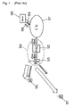
- a conventional mobile communication system comprises core network (CN) 91, and a radio access network (RAN) 94.
- Server 95 is connected to CN 91, while user equipment (UE) 96, 97 can be connected to RAN 94.
- image data is broadcast or multicast from server 95 to UE 96, 97.
- CN 91 which is a core of a mobile communication network, typically includes a plurality of switches (not shown) and can set an arbitrary communication route.
- RAN 94 which is responsible for accesses to the mobile communication network, includes radio network controller (RNC) 92 and base station device (Node-B) 93.
- Node-B 93 connects with UE 96, 97 over the air within a cell covered thereby to provide a radio channel for communications between UE 96, 97 and a partner device (here, server 95).
- RNC 92 is responsible for a variety of settings and control for Node-B 93, and for a calling process for establishing communications between UE 96, 97 and the partner device.
- Server 95 encodes an image in accordance with an encoding scheme which involves two layers with different importance levels when it broadcasts or multicasts image data to UE 96, 97. This encoding results in generation of base layer data 98 and enhanced layer data 99.
- Base layer data 98 and enhanced layer data 99 are sent from Node-B 93 through CN 91 and RNC 92. In this event, base layer data 98 and enhanced layer data 99 are transmitted through physical radio channels different from each other. Also, these radio channels are transmitted with transmission powers different from each other, depending on the importance level of each layer. Base layer data 98 is transmitted with higher transmission power than enhanced layer data 99 because base layer data 98 has a higher importance level.
- each UE 96, 97 Upon satisfactory receipt of both base layer data 98 and enhanced layer data 99, each UE 96, 97 displays a high resolution image using both data in decoding. On the other hand, when UE 96, 97 cannot satisfactorily receive enhanced layer data 99 but can satisfactorily receive only base layer data 98, each UE 96, 97 displays a low resolution image by decoding base layer data 98.
- UE 96 is under good communication conditions, because it is located near Node-B 93, and can therefore satisfactorily receive both base layer data 98 and enhanced layer data 99.
- UE 97 is under bad communication conditions because it is located far from Node-B 93, though located within the cell covered by Node-B 93, and can therefore satisfactorily receive only base layer data 98 which has higher transmission power.
- UE 96 under good communication conditions, can display a high resolution image
- UE 97 under bad communication conditions, can also display an image though the resolution is lower than that of the image displayed by UE 96.
- the conventional system has the ability to efficiently utilize the communication capacity by ensuring that an image is displayed even on UE under bad communication conditions, while degrading the resolution of the image, to reduce the total transmission power.
- one image is encoded into two data, i.e., base layer data and enhanced layer data which are transferred through different paths from each other, so that the system requires a call control which handles these data in pair. For this reason, extra processing must be added to CN 91, RNC 92, and UE 96, 97.
- base layer data and enhanced layer data of the same image pass CN 91 through different paths, a difference in delay must be absorbed before the image is decoded.
- the Internet may be connected to CN 91 through a gateway so that server 95 is connected to the Internet, the difference in delay is even increased in such a configuration.
- a buffer for temporality storing data is required for RNC 92 or UE 96, 97 in order to absorb the difference in delay.
- RNC 92 or UE 96, 97 requires extra processing for synchronizing the data using the buffer.
- the image communication system of the present invention includes a transmitter and a receiver.
- the transmitter encodes an image in accordance with a hierarchical coding scheme to generate a plurality of layer data, and performs error correction coding on each of at least one layer data including the lowermost layer data in accordance with an error correction coding scheme which gives higher correction capabilities to a lower layer than a higher layer, and transmits a plurality of layer data including the layer data subjected to the error correction coding onto a transmission path.
- the receiver corrects possible errors introduced on the transmission path into the layer data received from the transmitter in accordance with the error correction coding scheme, and decodes layer data received in a quality available for decoding to restore the image.
- the transmitter adds an error correcting code to each layer data generated in accordance with the hierarchical coding scheme to provide higher error correction capabilities for lower layer data, and transmits the layer data, while the receiver restores an image using layer data received in a quality available for decoding, as a result of error correction.
- the image communication system can ensure that the image is displayed on a receiver under bad communication conditions, while degrading the image quality thereof, thereby reducing the total transmission power.
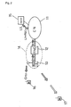
- a mobile communication system comprises core network (CN) 11, and radio access network (RAN) 14.
- Server 15 is connected to CN 11, while user equipment (UE) 16, 17 can be connected to RAN 14.
- UE user equipment
- image data is broadcast or multicast from server 15 to UE 16, 17.
- CN 11 which is the core of a mobile communication network, typically includes a plurality of switches (not shown) and can set an arbitrary communication route.
- RAN 14 which is responsible for accesses to the mobile communication network, includes radio network controller (RNC) 12 and base station device (Node-B) 13.
- Node-B 13 connects with UE 16, 17 over the air within a cell covered thereby to provide a radio channel for communications between UE 16, 17 and a partner device (here, server 15).
- RNC 12 is responsible for a variety of settings and control for Node-B 13, and for a calling process for establishing communications between UE 16, 17 and the partner device.
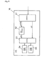
- server 15 comprises encoding unit 21, error correcting code addition unit 22, framing unit 23, image input unit 24, and image storage unit 25.
- Encoding unit 21 encodes image data applied from image input unit 24 or image data recorded in image storage unit 25 into a code comprised of two layers having different importance levels to generate two layer data in accordance with a hierarchical coding scheme.
- the hierarchical coding scheme encodes an image into data in a plurality of layers having different importance levels.
- data in a plurality of layers encoded in accordance with the hierarchical coding scheme can be decoded into an image using data in an arbitrary number of layers from the lowermost layer, and a better image can be restored as a larger number of layers are used in the decoding.
- the importance level used herein refers to the degree to which each layer is required for restoring an image, and a lower layer has a higher importance level in the hierarchical coding scheme.
- a layer having a higher importance level is Layer 1
- a layer having a lower importance level is Layer 2.
- Encoding unit 21 sends Layer 1 data (L1 in Fig. 3) to error correcting code addition unit 22, and sends Layer 2 data (L2 in Fig. 3) to framing unit 23.
- An image can be provided even by decoding only Layer 1 data which is in the lowermost layer of the data.
- the image provided from Layer 1 data alone is inferior in image quality to an image provided by decoding both Layer 1 data and Layer 2 data.
- an image sent in the image communication of this embodiment might be a still image or a moving image.
- the image quality used herein widely refers to the quality of a still image or a moving image, and includes smoothness of motion (temporal resolution) and the like when a moving image is concerned, in addition to reproductivity of an original image including, for example, the resolution and color.
- Fig. 4 is a diagram for describing an example of the hierarchical coding scheme.
- image is encoded at a predetermined resolution.
- each of pixels in Layer 1 is further sub-divided to encode the image at a higher resolution. While the image can be produced by decoding Layer 1 data alone, the resulting image has a lower resolution than the image produced using Layer 1 data and Layer 2 data.
- Error correcting code addition unit 22 adds an error correcting code (FEC in Fig. 3) to Layer 1 data from encoding unit 21, and sends the resulting data to framing unit 23.
- FEC error correcting code
- Framing unit 23 combines Layer 1 data to which the error correcting code was added in error correcting code addition unit 22 with layer 2 data from encoding unit 21 into a frame which is sent to CN 11.
- Fig. 5 is a diagram illustrating an exemplary structure of the frame sent from the server to mobile terminals.
- one frame includes Layer 1 data (L1), an error correcting code (FEC) added thereto, and Layer 2 data (L2). Since Layer 1 data, error correcting code added thereto, and Layer 2 data are sent through the same physical radio channel, CN11, RNC 12, Node-B 13 need not be conscious that an image is comprised of data in a plurality of layers, and therefore eliminate the need for the absorption of difference in delay and special processing. Also, the transmission power need not be adjusted for each radio channel, as is required in the conventional system in which Layer 1 data and Layer 2 data are sent through different radio channels, thus facilitating the processing of RNC 12 and Node-B 13.
- the frame including Layer 1 data and Layer 2 data is sent from Node-B 13 through CN 11 and RNC 12. In this event, the transmission power of the radio channel is adjusted to an appropriate value.
- UE 16 which is located near Node-B 13 and therefore is in a good communication state, can receive Layer 2 data without error correction in a quality available for decoding (for example, free of error) in addition to Layer 1 data with error correction.
- UE 16 comprises unframing unit 51, error correction unit 52, decoding unit 53, image display unit 54, and image storage unit 55.
- Unframing unit 51 receives a frame from server 15 through CN 11 and RAN 14, and extracts Layer 1 data and error correcting code added thereto, and Layer 2 data from the frame.
- the Layer 1 data and error correcting code added thereto are sent to error correction unit 52.
- the Layer 2 data is sent to decoding unit 53.
- Error correction unit 52 corrects possible errors in the Layer 1 data using the error correcting code, and sends the corrected Layer 1 data to decoding unit 53.
- Decoding unit 53 decodes both the Layer 1 data and Layer 2 data, if the Layer 2 data is in a quality available for decoding, to display a high quality image on image display unit 54 or record the image in image storage unit 55. On the other hand, when the Layer 2 data is not in a quality available for decoding, decoding unit 53 does not use the Layer 2 data in the decoding but decodes the Layer 1 data alone.
- UE 16 is under good communication conditions because it is located near Node-B 13, and can therefore display a high quality image.
- UE 17 is under bad communication conditions because it is located far away from Node-B 13, and can therefore decode only Layer 1 data and display an image though in a quality lower than that displayed by UE 16.
- the system of this embodiment can correct possible errors in only Layer 1 data having a higher importance level, using the error correcting code, of lower Layer 1 data and higher Layer 2 data to ensure that UE under bad communication conditions can display image anyway with the aid of error correction, while degrading the quality of the displayed image, to reduce the total transmission power.
- the system can save the power consumption, and efficiently utilize the communication capacity in the CDMA communication.
- the layer (Layer 2) having a lower importance level of the two layers is not given an error correcting code
- the present invention is not limited to this way of giving the error correcting code.
- the layer having a lower importance level may be given an error correcting code which provides lower error correcting capabilities than the error correcting code given to the layer (Layer 1) having a higher importance level.
- the present invention is not limited to such an encoding scheme that encodes an image into two layer data, but the number of layers may be any plural number.
- data in respective layers may be given error correcting codes which provide higher error correcting capabilities in an order in which the data have higher importance levels.
- Hierarchical coding scheme may employ any hierarchical coding scheme.
- Another example of hierarchical coding scheme may employ a quad-tree.
- Further examples of hierarchical coding scheme may employ progressive JPEG, interlace GIF, or JBIG.
- each of the vertical and horizontal sides of an image is divided by two, so that the image is divided into four areas. An entirely uniform area is no longer divided, but the remaining areas are each divided again into four areas. By repeating such division, the image can be represented by a small amount of data.
- the hierarchical coding can be implemented by separating a shallow portion and a deep portion of the quad-tree structure into layers.
- the foregoing embodiment has shown an example in Fig. 5 in which the Layer 1 data (L1), error correcting code (FEC), and Layer 2 data (L2) are included in the same frame.
- the present invention is not limited to this structure of frame.
- the Layer 1 data and Layer 2 data may be sequentially sent in different frames. Even in this way of transmission, the transmission power need not be adjusted on a channel-by-channel basis because UE 17 in bad communication conditions can receive Layer 1 data in a quality available for decoding with the aid of error correcting, even though UE 17 fails to receive Layer 2 data in a quality available for decoding.
- server 15 is connected CN 11
- the present invention is not limited to this particular topology.
- another network such as the Internet can be connected to CN 11 through a gateway, and the present invention can also be applied to such a topology.
Abstract
Description
Claims (20)
- An image communication method for sending an image from a transmitter to at least one receiver, said method comprising the steps of:in said transmitter:encoding said image in accordance with a hierarchical coding scheme to generate a plurality of layer data;performing error correction coding on each of said at least one layer data including the lowermost layer data in accordance with an error correction coding scheme which gives higher error correcting capabilities to lower layer data; andsending a plurality of said layer data including layer data subjected to said error correction coding to said receiver, andin each said receiver:correcting errors introduced on a transmission path into said layer data received from said transmitter in accordance with said error correction coding scheme; anddecoding layer data acquired in a quality available for decoding to restore the image.
- The image communication method according to claim 1, wherein said transmission path includes a section in which a CDMA scheme is employed.
- The image communication method according to claim 2, wherein transmission power is variable in said section in which the CDMA scheme is employed, and said layer data and the error correcting codes generated in said error correction coding are transmitted with the same transmission power.
- The image communication method according to claim 3, wherein each of said layer data and said error correcting codes is sent through the same physical channel on said transmission path.
- The image communication method according to claim 4, wherein each of said layer data and said error correcting codes is transmitted in the same frame.
- An image communication system comprising:a transmitter for encoding an image in accordance with a hierarchical coding scheme to generate a plurality of layer data, performing error correction coding on each of said at least one layer data including the lowermost layer data in accordance with an error correction coding scheme which gives higher error correcting capabilities to lower layer data, and sending a plurality of said layer data including layer data subjected to said error correction coding onto a transmission path, andat least one receiver for correcting errors introduced on a transmission path into said layer data received from said transmitter in accordance with said error correction coding scheme, and decoding layer data acquired in a quality available for decoding to restore the image.
- The image communication system according to claim 6, further comprising:wherein said receiver is a terminal device for receiving said layer data and said error correcting codes from said base station device through the section in which the CDMA scheme is employed.a base station device for transmitting each of said layer data and said error correcting codes to a section of said transmission path in which a CDMA scheme is used,
- The image communication system according to claim 7, wherein transmission power is variable in said section in which the CDMA scheme is employed, and said base station device transmits each of said layer data and said error correcting codes generated in said error correction coding with the same transmission power.
- The image communication system according to claim 8, wherein each of said layer data and said error correcting codes is transmitted through the same physical channel on said transmission path.
- The image communication system according to claim 9, wherein each of said layer data and said error correcting codes is transmitted in the same frame.
- An image transmitter for sending an image to at least one receiver, comprising:an encoding unit for encoding said image in accordance with a hierarchical coding scheme to generate a plurality of layer data;an error correcting code addition unit for performing error correction coding on each of said at least one layer data including the lowermost layer data in accordance with an error correction coding scheme which gives higher error correcting capabilities to lower layer data; anda transmission unit for sending a plurality of said layer data including layer data subjected to said error correcting codes to said receiver through a transmission path.
- The image transmitter according to claim 11, wherein said transmission path includes a section in which a CDMA scheme is employed.
- The image transmitter according to claim 12, wherein transmission power is variable in said section in which the CDMA scheme is employed, and said base station device transmits each of said layer data and said error correcting codes generated in said error correction coding with the same transmission power.
- The image transmitter according to claim 13, wherein said transmission unit transmits each of said layer data and said error correcting codes though the same physical channel on said transmission path.
- The image transmitter according to claim 14, wherein said transmission unit transmits each of said layer data and said error correcting codes in the same frame.
- An image receiver for receiving a plurality of layer data from a transmitter through a transmission path, said plurality of layer data generated by said transmitter in accordance with a hierarchical coding scheme, and each subjected to error correction coding in accordance with an error correction coding scheme which gives higher error correcting capabilities to lower layer data, said plurality of layer data received by said receiver including the layer data subjected to the error correction coding, said receiver comprising:a reception unit for receiving a plurality of said layer data;an error correction unit for correcting errors introduced on said transmission path into said layer data in accordance with said error correction coding; anda decoding unit for decoding layer data received in a quality available for decoding to restore an image.
- The image receiver according to claim 16, wherein said transmission path includes a section in which a CDMA scheme is employed.
- The image receiver according to claim 17, wherein transmission power is variable in said section in which the CDMA scheme is employed, and said base station device transmits each of said layer data and said error correcting codes generated in said error correction coding with the same transmission power.
- The image receiver according to claim 18, wherein said reception unit receives each of said layer data and said error correcting codes from the same physical channel on said transmission path.
- The image receiver according to claim 119, wherein said reception unit receives each of said layer data and said error correcting codes in the same frame.
Applications Claiming Priority (2)
| Application Number | Priority Date | Filing Date | Title |
|---|---|---|---|
| JP2003306455A JP2005079793A (en) | 2003-08-29 | 2003-08-29 | Image communication method, image communication system, image transmitter, and image receiver |
| JP2003306455 | 2003-08-29 |
Publications (2)
| Publication Number | Publication Date |
|---|---|
| EP1511321A2 true EP1511321A2 (en) | 2005-03-02 |
| EP1511321A3 EP1511321A3 (en) | 2010-07-28 |
Family
ID=34101241
Family Applications (1)
| Application Number | Title | Priority Date | Filing Date |
|---|---|---|---|
| EP20040020053 Withdrawn EP1511321A3 (en) | 2003-08-29 | 2004-08-24 | Image communication system using a hierarchical code comprised of a plurality of layers |
Country Status (4)
| Country | Link |
|---|---|
| US (1) | US7395486B2 (en) |
| EP (1) | EP1511321A3 (en) |
| JP (1) | JP2005079793A (en) |
| KR (2) | KR100675451B1 (en) |
Cited By (1)
| Publication number | Priority date | Publication date | Assignee | Title |
|---|---|---|---|---|
| CN102036085A (en) * | 2009-09-29 | 2011-04-27 | 索尼公司 | Transmitting device, receiving device, communication system and program |
Families Citing this family (5)
| Publication number | Priority date | Publication date | Assignee | Title |
|---|---|---|---|---|
| JP4604851B2 (en) * | 2005-06-02 | 2011-01-05 | ソニー株式会社 | Transmission device, reception device, transmission processing method, reception processing method, and program thereof |
| JP4727401B2 (en) * | 2005-12-02 | 2011-07-20 | 日本電信電話株式会社 | Wireless multicast transmission system, wireless transmission device, and wireless multicast transmission method |
| US8374254B2 (en) * | 2008-12-15 | 2013-02-12 | Sony Mobile Communications Ab | Multimedia stream combining |
| EP2200220A1 (en) * | 2008-12-22 | 2010-06-23 | Thomson Licensing | Method and apparatus for reliable multicast streaming |
| EP2395505A1 (en) * | 2010-06-11 | 2011-12-14 | Thomson Licensing | Method and apparatus for searching in a layered hierarchical bit stream followed by replay, said bit stream including a base layer and at least one enhancement layer |
Citations (1)
| Publication number | Priority date | Publication date | Assignee | Title |
|---|---|---|---|---|
| WO2003049449A2 (en) * | 2001-12-05 | 2003-06-12 | Koninklijke Philips Electronics N.V. | Modulation algorithm for a mpeg-4 fgs wireless transmission system |
Family Cites Families (12)
| Publication number | Priority date | Publication date | Assignee | Title |
|---|---|---|---|---|
| US5771081A (en) | 1994-02-28 | 1998-06-23 | Korea Telecommunication Authority | Bit system for transmitting digital video data |
| US5668810A (en) * | 1995-04-26 | 1997-09-16 | Scientific-Atlanta, Inc. | Data transmission protocol method and apparatus |
| JP2912851B2 (en) | 1995-06-16 | 1999-06-28 | 松下電器産業株式会社 | Heat storage combustion heating device |
| JP2980549B2 (en) * | 1996-03-19 | 1999-11-22 | エヌ・ティ・ティ移動通信網株式会社 | Wired line information transmission method in mobile communication system, base station apparatus and mobile station apparatus |
| US6292591B1 (en) * | 1996-07-17 | 2001-09-18 | Sony Coporation | Image coding and decoding using mapping coefficients corresponding to class information of pixel blocks |
| DE69833821T2 (en) * | 1997-09-18 | 2006-11-30 | Matsushita Electric Industrial Co., Ltd., Kadoma | Transmission method and apparatus for combined multiplexing and encrypting |
| JP2000078573A (en) * | 1998-09-03 | 2000-03-14 | Hitachi Ltd | Hierarchical encoded data distribution device |
| US6317462B1 (en) * | 1998-10-22 | 2001-11-13 | Lucent Technologies Inc. | Method and apparatus for transmitting MPEG video over the internet |
| US6490705B1 (en) * | 1998-10-22 | 2002-12-03 | Lucent Technologies Inc. | Method and apparatus for receiving MPEG video over the internet |
| US6516436B1 (en) * | 1999-03-04 | 2003-02-04 | Lucent Technologies Inc. | Error control coding for transmission equipment protection |
| US6901159B2 (en) * | 2001-01-31 | 2005-05-31 | General Electric Company | Communication of image data from image detector to host computer |
| US20050063596A1 (en) * | 2001-11-23 | 2005-03-24 | Yosef Yomdin | Encoding of geometric modeled images |
-
2003
- 2003-08-29 JP JP2003306455A patent/JP2005079793A/en active Pending
-
2004
- 2004-08-24 US US10/924,216 patent/US7395486B2/en not_active Expired - Fee Related
- 2004-08-24 KR KR20040066617A patent/KR100675451B1/en not_active IP Right Cessation
- 2004-08-24 EP EP20040020053 patent/EP1511321A3/en not_active Withdrawn
-
2006
- 2006-09-29 KR KR1020060095289A patent/KR20060123037A/en not_active Application Discontinuation
Patent Citations (1)
| Publication number | Priority date | Publication date | Assignee | Title |
|---|---|---|---|---|
| WO2003049449A2 (en) * | 2001-12-05 | 2003-06-12 | Koninklijke Philips Electronics N.V. | Modulation algorithm for a mpeg-4 fgs wireless transmission system |
Non-Patent Citations (5)
| Title |
|---|
| LIU H ET AL: "Transmission of video telephony images over wireless channels" WIRELESS NETWORKS, vol. 2, no. 3, August 1996 (1996-08), pages 219-228, XP000625340 ACM, New York, NY, US ISSN: 1022-0038 * |
| SANGHOON L ET AL: "Unequal error protection for foveation-based error resilience over mobile networks" PROCEEDINGS OF THE 2000 INTERNATIONAL CONFERENCE ON IMAGE PROCESSING (ICIP 2000), vol. 2, 10 September 2000 (2000-09-10), pages 140-143, XP010529943 IEEE, Piscataway, US ISBN: 978-0-7803-6297-0 * |
| TINGTING Z ET AL: "Unequal Packet Loss Protection for Layered Video Transmission" IEEE TRANSACTIONS ON BROADCASTING, vol. 45, no. 2, June 1999 (1999-06), pages 243-252, XP011083069 IEEE, Piscataway, US ISSN: 0018-9316 * |
| VAN DER SCHAAR M ET AL: "Robust Transmission of MPEG-4 Scalable Video over 4G Wireless Networks" PROCEEDINGS OF THE 2002 INTERNATIONAL CONFERENCE ON IMAGE PROCESSING (ICIP 2002), vol. 3, 22 September 2002 (2002-09-22), pages 757-760, XP010607828 IEEE, Piscataway, US ISBN: 978-0-7803-7622-9 * |
| YANG X K ET AL: "A degressive error protection algorithm for MPEG-4 FGS video streaming" PROCEEDINGS OF THE 2002 INTERNATIONAL CONFERENCE ON IMAGE PROCESSING (ICIP 2002), vol. 3, 22 September 2002 (2002-09-22), pages 737-740, XP010607823 IEEE, Piscataway, US ISBN: 978-0-7803-7622-9 * |
Cited By (1)
| Publication number | Priority date | Publication date | Assignee | Title |
|---|---|---|---|---|
| CN102036085A (en) * | 2009-09-29 | 2011-04-27 | 索尼公司 | Transmitting device, receiving device, communication system and program |
Also Published As
| Publication number | Publication date |
|---|---|
| KR20050022351A (en) | 2005-03-07 |
| EP1511321A3 (en) | 2010-07-28 |
| US20050050430A1 (en) | 2005-03-03 |
| US7395486B2 (en) | 2008-07-01 |
| KR100675451B1 (en) | 2007-01-26 |
| KR20060123037A (en) | 2006-12-01 |
| JP2005079793A (en) | 2005-03-24 |
Similar Documents
| Publication | Publication Date | Title |
|---|---|---|
| JP5801443B2 (en) | Mobile station-centric method for managing bandwidth and QoS in error prone systems | |
| US7508791B2 (en) | Wireless communication coding and transmission systems and methods | |
| Wang et al. | Low-delay and error-robust wireless video transmission for video communications | |
| Yao et al. | IP datacasting and channel error handling with DVB-H | |
| US20040240415A1 (en) | Base station-centric method for managing bandwidth and QoS in error-prone system | |
| KR20060123037A (en) | Image communication system using a hierarchical code comprised of a plurality of layers | |
| WO2001095512A1 (en) | System and method for object-oriented video processing | |
| Bajic | Efficient cross-layer error control for wireless video multicast | |
| CN101820327B (en) | Relay transmission method, system and equipment combining multi-description characteristics of information source | |
| Wang et al. | An efficient retransmission strategy for wireless scalable video multicast | |
| JP2015532794A (en) | Method and apparatus for cross-layer coding of satellite mobile TV broadcast | |
| CN112737728B (en) | Data processing method and device | |
| Chen et al. | A qoe-based app layer scheduling scheme for scalable video transmissions over multi-rat systems? | |
| Ho et al. | QoS-supporting video streaming system with minimum data service cost over heterogeneous wireless networks | |
| Jenkac et al. | H. 264/AVC video transmission over MBMS in GERAN | |
| Deep et al. | Adaptive code allocation in multicode-CDMA for transmitting H. 263 video | |
| Kim et al. | A new leader-based multicast scheme with a Raptor code in IEEE 802.11 multi-rate WLANs | |
| Fujihashi et al. | Wi-Fi Offloading for Multi-Homed Hybrid Digital-Analog Video Streaming | |
| CN116743318A (en) | Packet loss data recovery method, device, equipment and storage medium | |
| Chen et al. | Layered multimedia broadcast using rateless codes with progressive recovery over cooperative MIMO | |
| Aissa | Robust Image Transmission over Wireless CDMA Channels Using CombinedError-Resilient Source Coding and Channel Error Control | |
| HUANG et al. | Feedback-based unequal error protection fountain code over device-to-device broadcast |
Legal Events
| Date | Code | Title | Description |
|---|---|---|---|
| PUAI | Public reference made under article 153(3) epc to a published international application that has entered the european phase |
Free format text: ORIGINAL CODE: 0009012 |
|
| AK | Designated contracting states |
Kind code of ref document: A2 Designated state(s): AT BE BG CH CY CZ DE DK EE ES FI FR GB GR HU IE IT LI LU MC NL PL PT RO SE SI SK TR |
|
| AX | Request for extension of the european patent |
Extension state: AL HR LT LV MK |
|
| PUAL | Search report despatched |
Free format text: ORIGINAL CODE: 0009013 |
|
| AK | Designated contracting states |
Kind code of ref document: A3 Designated state(s): AT BE BG CH CY CZ DE DK EE ES FI FR GB GR HU IE IT LI LU MC NL PL PT RO SE SI SK TR |
|
| AX | Request for extension of the european patent |
Extension state: AL HR LT LV MK |
|
| RIC1 | Information provided on ipc code assigned before grant |
Ipc: H04N 7/50 20060101ALI20100622BHEP Ipc: H04N 7/30 20060101ALI20100622BHEP Ipc: H04N 7/26 20060101AFI20041217BHEP |
|
| 17P | Request for examination filed |
Effective date: 20101229 |
|
| AKX | Designation fees paid |
Designated state(s): DE FI FR GB |
|
| STAA | Information on the status of an ep patent application or granted ep patent |
Free format text: STATUS: THE APPLICATION IS DEEMED TO BE WITHDRAWN |
|
| 18D | Application deemed to be withdrawn |
Effective date: 20140301 |