EP1510830A1 - Estimating GPS reference frequency drift from PDC-handset VCO-bursts - Google Patents
Estimating GPS reference frequency drift from PDC-handset VCO-bursts Download PDFInfo
- Publication number
- EP1510830A1 EP1510830A1 EP04019596A EP04019596A EP1510830A1 EP 1510830 A1 EP1510830 A1 EP 1510830A1 EP 04019596 A EP04019596 A EP 04019596A EP 04019596 A EP04019596 A EP 04019596A EP 1510830 A1 EP1510830 A1 EP 1510830A1
- Authority
- EP
- European Patent Office
- Prior art keywords
- nco
- output
- vco
- mclk
- drift
- Prior art date
- Legal status (The legal status is an assumption and is not a legal conclusion. Google has not performed a legal analysis and makes no representation as to the accuracy of the status listed.)
- Granted
Links
Images
Classifications
-
- G—PHYSICS
- G01—MEASURING; TESTING
- G01C—MEASURING DISTANCES, LEVELS OR BEARINGS; SURVEYING; NAVIGATION; GYROSCOPIC INSTRUMENTS; PHOTOGRAMMETRY OR VIDEOGRAMMETRY
- G01C21/00—Navigation; Navigational instruments not provided for in groups G01C1/00 - G01C19/00
- G01C21/04—Navigation; Navigational instruments not provided for in groups G01C1/00 - G01C19/00 by terrestrial means
- G01C21/06—Navigation; Navigational instruments not provided for in groups G01C1/00 - G01C19/00 by terrestrial means involving measuring of drift angle; involving correction for drift
-
- G—PHYSICS
- G01—MEASURING; TESTING
- G01S—RADIO DIRECTION-FINDING; RADIO NAVIGATION; DETERMINING DISTANCE OR VELOCITY BY USE OF RADIO WAVES; LOCATING OR PRESENCE-DETECTING BY USE OF THE REFLECTION OR RERADIATION OF RADIO WAVES; ANALOGOUS ARRANGEMENTS USING OTHER WAVES
- G01S19/00—Satellite radio beacon positioning systems; Determining position, velocity or attitude using signals transmitted by such systems
- G01S19/01—Satellite radio beacon positioning systems transmitting time-stamped messages, e.g. GPS [Global Positioning System], GLONASS [Global Orbiting Navigation Satellite System] or GALILEO
- G01S19/13—Receivers
- G01S19/23—Testing, monitoring, correcting or calibrating of receiver elements
- G01S19/235—Calibration of receiver components
-
- G—PHYSICS
- G01—MEASURING; TESTING
- G01S—RADIO DIRECTION-FINDING; RADIO NAVIGATION; DETERMINING DISTANCE OR VELOCITY BY USE OF RADIO WAVES; LOCATING OR PRESENCE-DETECTING BY USE OF THE REFLECTION OR RERADIATION OF RADIO WAVES; ANALOGOUS ARRANGEMENTS USING OTHER WAVES
- G01S19/00—Satellite radio beacon positioning systems; Determining position, velocity or attitude using signals transmitted by such systems
- G01S19/01—Satellite radio beacon positioning systems transmitting time-stamped messages, e.g. GPS [Global Positioning System], GLONASS [Global Orbiting Navigation Satellite System] or GALILEO
- G01S19/13—Receivers
- G01S19/20—Integrity monitoring, fault detection or fault isolation of space segment
-
- H—ELECTRICITY
- H04—ELECTRIC COMMUNICATION TECHNIQUE
- H04B—TRANSMISSION
- H04B7/00—Radio transmission systems, i.e. using radiation field
- H04B7/24—Radio transmission systems, i.e. using radiation field for communication between two or more posts
- H04B7/26—Radio transmission systems, i.e. using radiation field for communication between two or more posts at least one of which is mobile
Definitions
- the present invention relates to navigation satellite receivers, and more particularly to methods and systems for operating navigation satellite receivers in conjunction with cellular telephones.
- GSM global system for mobile telecommunications
- GSM 900 GSM 900
- CDMA code division multiple access
- IS-95 International Standard
- PDC personal digital communicator
- Typical PDC handsets in standby mode only adjust their voltage-controlled oscillator (VCO) in twenty millisecond bursts every 700 milliseconds.
- VCO voltage-controlled oscillator
- the periods in which the handset-VCO is actively being locked with a synchronizing burst can provide a good synthesized reference frequency for satellite navigation receiver operation. But the available observation window is not long enough for a frequency counter approach to be used to estimate the satellite navigation receiver drift.
- What is needed is a circuit that can borrow timing information from PDC type VCO's in order to help initialize and operate a GPS receiver.
- a combination mobile phone and navigation satellite receiver embodiment of the present invention comprises a circuit for correcting GPS receiver reference frequency drift by using VCO burst information periodically received by a PDC handset.
- a corrected GPS receiver reference frequency drift then enables faster initialization and stable operation of the position solutions made available to users.
- a GPS numeric controlled oscillator (NCO) receives a PDC handset VCO sample.
- An advantage of the present invention is that a system and method are provided for initialization and operation of navigation satellite receivers.
- Another advantage of the present invention is that a system and method are provided for reducing the cost of mobile devices with navigation satellite receivers associated and mobile telephones.
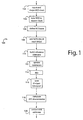
- Fig. 1 illustrates a method embodiment of the present invention for estimating GPS reference frequency drift from a phone VCO in standby mode. Such method is referred to herein by the general reference numeral 100.
- standby mode typical PDC handsets adjust their VCO's in 20msec bursts every 700msec. An observation window this short is not long enough to estimate the GPS drift using a conventional frequency counter approach. Circuit 100 is able to accurately estimate the GPS drift, assuming the VCO is locked but available only a short time.
- a handset VCO clock is input and converted into a square wave with a reasonable duty cycle.
- the VCO clock is synchronized or gated to a GPS receiver master clock in a step 104.
- a gated VCO clock variable (VCOstate) is defined in a step 106 as having two states, (1) TTL high, and (-1) TTL low.
- An NCO with an input clock, MCLK, e.g., 27.456 MHz includes a 24-bit counter that adds an "NCO_VALUE" each MCLK in a step 108.
- the full master clock is used so VCO frequencies all the way up to MCLK can be accommodated.
- Input commands are preferably used to define the nominal VCO frequency.
- NCO_VALUE VCO * 2 24 / MCLK.
- Istate is equal to the top 4-bits of the NCO.
- Qstate Istate + 4, is defined.
- Each MCLK, a reference sine and cosine function are built in a step 110 using a sinusoidal table, where Istate and Qstate are the inputs to the table.
- a signed 18-bit correlator is adequate for a one-msec integration at 27.456MHz.
- Another variable, for the pre-detection interval, "PDI" is defined.
- the length of the PDI variable is a function of GPS drift being solved. The PDI is selected such that it will not be aliased in the observation time.
- DRIFT_ERROR ⁇ 2 / MIX_PDI, where DRIFT_ERROR is in Hz at NCO_NOMINAL, e.g., if the drift error is 10PPM, the error at nominal is 274.56Hz. Thus, for a 1msec PDI, the drift is within the detectable range of 500Hz.
- the frequency will be aliased. This might still be acceptable is there is an SCXO model to enable detection of aliasing.
- NUM_CLKS NUM_CLKS * period of MCLK, and equals NUM_CLKS / (MCLK + drift(at MCLK)).
- the circuit 100 For frequency assistance while the phone is in standby mode, the circuit 100 preferably executes in background before a GPS fix is needed. When a GPS fix is requested, a "hot" drift estimate is available and there will be no delay GPS time-to-first-fix (TTFF) waiting for frequency assist.
- TTFF GPS time-to-first-fix
- consecutive 1-MSEC estimates are preferably collected and averaged to further reduce the error.
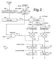
- Fig. 2 illustrates a second embodiment of the present invention
- a discriminator 200 is used to measure frequency differences between the GPS clock and an external VCO clock.
- a conventional freqDiff circuit provides good precision if the observation interval is long with respect to the external clock frequency. In applications where the external clock is only observable for short periods, a different type of circuit is needed.
- the freqDiff2 circuit is a simple quadrature detector, in which sequential observations provide frequency error detection.
- a numeric controlled oscillator (NCO) latch 202 receives any writes from a firmware control program for an NCO 204.
- An NCO value 206 is written periodically as VCO information is obtained, e.g., from a PDC handset in standby mode.
- the NCO 204 is used to generate an external clock's nominal frequency. For example, to determine the difference in frequency between a master clock (MCLK) 208 and an external clock input 210, the nominal frequency is generated with the NCO to form a quadrature error signal.
- MCLK master clock
- a quadrature version (cosine) 216 is created by a digital delay 218 to advance the Istate by four states (90-degrees).
- Qstate (Istate + 4) & 0xF.
- the Istate and Qstate are both input to respective 16-state lookup tables 220 and 222, e.g., Table Input 0 1 2 3 4 5 6 7 8 9 10 11 12 13 14 15 Table output 1 3 4 5 5 4 3 1 -1 -3 -4 -5 -5 -4 -3 -1
- the external clock is gated by a gate 224 with MCLK and for a variable, Input, which has logical value of (0,1). If the external clock is a logical (TTL) high state (1), then it gets a numerical value of "1". Otherwise, it has the low state (0) and gets the value "-1".
- TTL logical
- An I-mixer 226 and a Q-mixer 227 respectively feed an I-correlator 228 and a Q-correlator 230.
- Such correlators are cleared. Counting begins at a next millisecond interrupt. An interrupt may be produced at each millisecond. The first values will be zero and are preferably discarded by the firmware. Every millisecond, the Icorr and Qcorr values are latched into respective holding registers 232 and 234. The correlators are cleared and the integration continues until the circuit is halted.
- An observation period of a half millisecond may be useful for estimating larger frequency differences.
- the circuit 200 is controlled by writing an NCO_VALUE.
- the copying of a word into the circuit happens when the most significant byte is written.
- An bit set in NCO_VALUE indicates the circuit is enabled. All zeros indicates the circuit is disabled.
- the clock enable set off, all three bytes of input NCO_VALUE are set to zero, and the NCO and correlators are cleared; (2) the clock enable is set on if any bit of NCO_VALUE is set, and upper byte written, clock enabled after a next correlator strobe; (3) NCO is run at MCLK; (4) the clock gate gates the input clock with the master clock; (5) Iphase is a 4-bit word, and Qphase is a 4-bit word advanced from I by 4; (6) the Ivalue and Qvalue results from table lookup; (7) Imix and Qmix are products of input (+/-1) times table output; (8) the correlators are 24-bit adders, e.g., 4-bit pre-adder, 20-bit up/down counter; (9) a correlator strobe is set as a millisecond interrupt; (10) the latches are readable from the host as the drift estimate; (11) a bit is set in int2 status when one msec integration is
Abstract
Description
- The present invention relates to navigation satellite receivers, and more particularly to methods and systems for operating navigation satellite receivers in conjunction with cellular telephones.
- Cellular telephones have become ubiquitous, they are everywhere and everyone seems to be using them. Global positioning system (GPS) and other satellite navigation systems are now becoming associated with cellphones so that the position of the user can be determined for both legal and convenience reasons. The United States Government has mandated that cellular providers should report the physical locations of cellphones for emergency 9-1-1 system reasons. But law enforcement also wants to be able to locate criminals who have so-far been able to skirt apprehension by using roaming cellphones. Users and companies have found myriad reasons why it would be good and useful to know the location of theirs and their customer's cellphones. So a marriage of cellular phone and satellite navigation receiver technologies in one mass-marketed handheld device has become critical.
- Two things are important in any mass-marketed handheld device, manufacturing cost and battery life. In a hybrid of cellular phone and satellite navigation receiver technologies, it seems appropriate to share tasks and make as many components do double duty as possible. The most obvious is to put the cellphone and satellite navigation receiver in one package and to use one battery to power both. One prior art hybrid device attempts to reduce the number of crystal oscillators needed by slaving the satellite navigation receiver reference frequency input to an output synthesized from the cellphone part.
- There are a number of cellphone technologies in use throughout the world. The global system for mobile telecommunications (GSM), e.g., GSM 900, is a mobile phone standard established mainly in Europe, South East Asia, Australia and Africa. North America uses code division multiple access (CDMA) digital wireless technology, e.g., International Standard (IS-95), and several other network technologies which are not compatible with the GSM networks used in Europe. Japan uses CDMA and personal digital communicator (PDC) for its mobile phone networks. GSM phones are incompatible and do not work in Japan.
- Typical PDC handsets in standby mode only adjust their voltage-controlled oscillator (VCO) in twenty millisecond bursts every 700 milliseconds. The VCO drift between these bursts is of no consequence to PDC system operation, but such drift exceeds the stringent limits of satellite navigation receiver operation. The periods in which the handset-VCO is actively being locked with a synchronizing burst can provide a good synthesized reference frequency for satellite navigation receiver operation. But the available observation window is not long enough for a frequency counter approach to be used to estimate the satellite navigation receiver drift.
- What is needed is a circuit that can borrow timing information from PDC type VCO's in order to help initialize and operate a GPS receiver.
- Briefly, a combination mobile phone and navigation satellite receiver embodiment of the present invention comprises a circuit for correcting GPS receiver reference frequency drift by using VCO burst information periodically received by a PDC handset. A corrected GPS receiver reference frequency drift then enables faster initialization and stable operation of the position solutions made available to users. A GPS numeric controlled oscillator (NCO) receives a PDC handset VCO sample.
- An advantage of the present invention is that a system and method are provided for initialization and operation of navigation satellite receivers.
- Another advantage of the present invention is that a system and method are provided for reducing the cost of mobile devices with navigation satellite receivers associated and mobile telephones.
- These and other objects and advantages of the present invention will no doubt become obvious to those of ordinary skill in the art after having read the following detailed description of the preferred SPS receivers which are illustrated in the various drawing figures.
-
- Fig. 1 is a flowchart diagram of a method embodiment of the present invention; and
- Fig. 2 is a schematic diagram of a discriminator circuit embodiment of the present invention alternative to the method of Fig. 1.
-
- Fig. 1 illustrates a method embodiment of the present invention for estimating GPS reference frequency drift from a phone VCO in standby mode. Such method is referred to herein by the
general reference numeral 100. In standby mode, typical PDC handsets adjust their VCO's in 20msec bursts every 700msec. An observation window this short is not long enough to estimate the GPS drift using a conventional frequency counter approach.Circuit 100 is able to accurately estimate the GPS drift, assuming the VCO is locked but available only a short time. - In a
step 102, a handset VCO clock is input and converted into a square wave with a reasonable duty cycle. The VCO clock is synchronized or gated to a GPS receiver master clock in astep 104. A gated VCO clock variable (VCOstate) is defined in astep 106 as having two states, (1) TTL high, and (-1) TTL low. An NCO with an input clock, MCLK, e.g., 27.456 MHz includes a 24-bit counter that adds an "NCO_VALUE" each MCLK in astep 108. The full master clock is used so VCO frequencies all the way up to MCLK can be accommodated. Input commands are preferably used to define the nominal VCO frequency. Thus, NCO_VALUE = VCO * 224 / MCLK. A 4-bit variable, Istate, is equal to the top 4-bits of the NCO. A second 4-bit variable, Qstate = Istate + 4, is defined. Each MCLK, a reference sine and cosine function are built in astep 110 using a sinusoidal table, where Istate and Qstate are the inputs to the table. For example,table[0] = 1; table[1] = 3; table[2] = 4; table[3] = 5; table[4] = 5; table[5] = 4; table[6] = 3; table[7] = 1; table[8] = -1; table[9] = -3; table[10] = -4; table[11] = -5; table[12] = -5; table[13] = -4; table[14] = -3; table[15] = -1. - In a
step 112, each MCLK, two correlators are updated according to a carrier mix, Icorr += VCOstate * table[Istate], and Qcorr += VCOstate * table[Qstate]. A signed 18-bit correlator is adequate for a one-msec integration at 27.456MHz. Another variable, for the pre-detection interval, "PDI" is defined. For astep 114, the length of the PDI variable is a function of GPS drift being solved. The PDI is selected such that it will not be aliased in the observation time. DRIFT_ERROR < 2 / MIX_PDI, where DRIFT_ERROR is in Hz at NCO_NOMINAL, e.g., if the drift error is 10PPM, the error at nominal is 274.56Hz. Thus, for a 1msec PDI, the drift is within the detectable range of 500Hz. - If the PDI is too long, the frequency will be aliased. This might still be acceptable is there is an SCXO model to enable detection of aliasing. A preferred approach defines the PDI to be long enough to reduce noise, but also short enough to prevent aliasing of the worst GPS drift offset. For example, a 25PPM drift error = 686.4Hz. A PDI of 0.5msec has an alias at 1kHz, so the drift value could be properly computed.
- At the end of a first PDI, the I1 = Icorr and Q2 = Qcorr are saved in a
step 116. During a second PDI, 12 = Icorr and Q2 = Qcorr are saved. The standard AFC discriminator is computed in astep 118, Cross = I1 * Q2 - I2 * Q1, and Dot = I1 * I2 + Q1 * Q2. Forming the ratio X = Cross / Dot. From trigonometry, X = tan [ (ωvcoError - ωgpsError VCO ) * PDI ] . Where ωvcoError = radian frequency error of the VCO from nominal, and equals True VCO frequency - VCO_NOMINAL, where ωgpsError VCO = radian frequency error of the GPS crystal from nominal expressed at the VCO nominal frequency. - Thus,
- So,
- Assuming that ωvcoError = 0, the GPS frequency error is
- An estimate of the GPS reference drift is thus available in a
step 120. The accuracy of the calculation can be improved by recognizing the PDI is formed by counting MCLKs. It is affected by the drift being solved for. This can be accounted for by modeling the fact that the real PDI equals NUM_CLKS * period of MCLK, and equals NUM_CLKS / (MCLK + drift(at MCLK)). NUM_CLKS is expressed as the number of MSEC, NUM_CLKS = MSEC * 0.001 * MCLK. - Making two substitutions,(0 - 2 * PI * drift * VCO /MCLK) * MSEC * 0.001 * MCLK / (MCLK + drift) = tan-1(X) . Solving for drift, Drift(at MCLK) = tan-1(X) * MCLK /(2*PI*0.001*MSEC*VCO + tan-1(X) )
- Using a 13PPM GPS error, the true frequency is 27,456,356.93Hz. Thus, drift true = 356.93Hz. In 1000 experimental runs using a MSEC=1, the average frequency was 355.97Hz, with an error of 0.96Hz. Such led to an average PPM error = 0.035PPM, and a standard deviation of 0.026PPM.
- For frequency assistance while the phone is in standby mode, the
circuit 100 preferably executes in background before a GPS fix is needed. When a GPS fix is requested, a "hot" drift estimate is available and there will be no delay GPS time-to-first-fix (TTFF) waiting for frequency assist. - During each 20msec standby period, consecutive 1-MSEC estimates are preferably collected and averaged to further reduce the error.
- Fig. 2 illustrates a second embodiment of the present invention, a
discriminator 200 is used to measure frequency differences between the GPS clock and an external VCO clock. A conventional freqDiff circuit provides good precision if the observation interval is long with respect to the external clock frequency. In applications where the external clock is only observable for short periods, a different type of circuit is needed. The freqDiff2 circuit is a simple quadrature detector, in which sequential observations provide frequency error detection. - In
circuit 200, a numeric controlled oscillator (NCO)latch 202 receives any writes from a firmware control program for anNCO 204. AnNCO value 206 is written periodically as VCO information is obtained, e.g., from a PDC handset in standby mode. - The
NCO 204 is used to generate an external clock's nominal frequency. For example, to determine the difference in frequency between a master clock (MCLK) 208 and anexternal clock input 210, the nominal frequency is generated with the NCO to form a quadrature error signal. - The
NCO 204 is preferably a 24-bit unsigned adder that adds avariable NCO_VALUE 212 each master clock. For each MCLK of the 27.456MHz clock 208 passed by a clock enablegate 209, theNCO 204 adds theNCO_VALUE 212 to the previous value. Aninput 210 controls a clock gate. Afrequency signal 214 produced by theNCO 204 is a function of the NCO_VALUE. The circuit converts the MCLK to the desired frequency. NCO_VALUE (bits) = desired frequency (Hz) * 224 (bits) / MCLK (Hz). The top 4-bits of the NCO are used in adigital delay 216 to produce a 16-bit phase sine variable, Istate, where Istate = NCO >> 20. A quadrature version (cosine) 216 is created by adigital delay 218 to advance the Istate by four states (90-degrees). Qstate = (Istate + 4) & 0xF. The Istate and Qstate are both input to respective 16-state lookup tables 220 and 222, e.g.,Table Input 0 1 2 3 4 5 6 7 8 9 10 11 12 13 14 15 Table output 1 3 4 5 5 4 3 1 -1 -3 -4 -5 -5 -4 -3 -1 - The external clock is gated by a
gate 224 with MCLK and for a variable, Input, which has logical value of (0,1). If the external clock is a logical (TTL) high state (1), then it gets a numerical value of "1". Otherwise, it has the low state (0) and gets the value "-1".Each MCLK: If (input = 1) Icorr += table(Istate) Qcorr += table(Qstate) Else Icorr -= table(Istate) Qcorr -= table(Qstate) - An I-
mixer 226 and a Q-mixer 227 respectively feed an I-correlator 228 and a Q-correlator 230. When thecircuit 200 is enabled, such correlators are cleared. Counting begins at a next millisecond interrupt. An interrupt may be produced at each millisecond. The first values will be zero and are preferably discarded by the firmware. Every millisecond, the Icorr and Qcorr values are latched into respective holding registers 232 and 234. The correlators are cleared and the integration continues until the circuit is halted. - An observation period of a half millisecond may be useful for estimating larger frequency differences. The maximum theoretical value for each correlator in one millisecond is, 27456 * 5 = 137280. Since, 217= 131072, and 218 = 262144, the registers Icorr and Qcorr can each be 18-bit signed registers. The results are sign-extended into a 24-bit word. A freqDiff2 interrupt bit is used to report when the circuit is enabled and has a new result.
- The
circuit 200 is controlled by writing an NCO_VALUE. The copying of a word into the circuit happens when the most significant byte is written. An bit set in NCO_VALUE indicates the circuit is enabled. All zeros indicates the circuit is disabled. - For a read operation, (1) the clock enable set off, all three bytes of input NCO_VALUE are set to zero, and the NCO and correlators are cleared; (2) the clock enable is set on if any bit of NCO_VALUE is set, and upper byte written, clock enabled after a next correlator strobe; (3) NCO is run at MCLK; (4) the clock gate gates the input clock with the master clock; (5) Iphase is a 4-bit word, and Qphase is a 4-bit word advanced from I by 4; (6) the Ivalue and Qvalue results from table lookup; (7) Imix and Qmix are products of input (+/-1) times table output; (8) the correlators are 24-bit adders, e.g., 4-bit pre-adder, 20-bit up/down counter; (9) a correlator strobe is set as a millisecond interrupt; (10) the latches are readable from the host as the drift estimate; (11) a bit is set in int2 status when one msec integration is complete, e.g., to avoid setting interrupt at when circuit is enabled by detecting both I and Q latch are zero.
- Although the present invention has been described in terms of the presently preferred SPS receivers, it is to be understood that the disclosure is not to be interpreted as limiting. Various alterations and modifications will no doubt become apparent to those skilled in the art after having read the above disclosure. Accordingly, it is intended that the appended claims be interpreted as covering all alterations and modifications as fall within the "true" spirit and scope of the invention.
Claims (5)
- A method for estimating reference frequency drift in a navigation receiver, the method comprising the steps of:associating a PDC handset subject to standby mode with a navigation receiver;sampling a VCO burst information that is received by said PDC handset;running a numeric controlled oscillator (NCO) at a nominal frequency;periodically adjusting said NCO with samples obtained in the step of sampling;correlating both in-phase and quadrature-phase outputs of said NCO; andcomputing a navigation receiver reference frequency drift estimate from information derived in the step of correlating.
- The method of claim 1, further comprising the step of:building a reference sinewave from data output by said NCO and passing such as updates to the step of correlating.
- A circuit for estimating reference frequency drift in a navigation receiver, comprising:a numeric controlled oscillator (NCO) for periodically receiving an NCO_value on which an NCO output frequency depends;a first lookup table for approximating a sinewave from an inphase version of said NCO output frequency;a first mixer connected to an output of the first lookup table and for combining it with a gated master clock (MCLK) signal, and providing further for an I-mix signal output;an I-correlator for correlating said I-mix signal output and having an I-correlation output;a second lookup table for approximating a cosine wave from a quadrature phase version of said NCO output frequency;a second mixer connected to an output of the second lookup table and for combining it with said gated master clock (MCLK) signal, and providing further for a Q-mix signal output;a Q-correlator for correlating said Q-mix signal output and having an Q-correlation output; anda drift estimate output comprising said I-correlation and Q-correlation outputs.
- The circuit of claim 3, further comprising:an NCO value holding latch for receiving a data write from a firmware control program, and connected to gate an MCLK signal to the first and second mixers.
- The circuit of claim 3, further comprising:an I-latch and a Q-latch providing for a register of said I-correlation and Q-correlation outputs to a data read from a firmware control program.
Applications Claiming Priority (2)
| Application Number | Priority Date | Filing Date | Title |
|---|---|---|---|
| US650383 | 2003-08-27 | ||
| US10/650,383 US7224950B2 (en) | 2003-08-27 | 2003-08-27 | Estimating GPS reference frequency drift from PDC-handset VCO-bursts |
Publications (2)
| Publication Number | Publication Date |
|---|---|
| EP1510830A1 true EP1510830A1 (en) | 2005-03-02 |
| EP1510830B1 EP1510830B1 (en) | 2006-06-28 |
Family
ID=34104702
Family Applications (1)
| Application Number | Title | Priority Date | Filing Date |
|---|---|---|---|
| EP04019596A Expired - Fee Related EP1510830B1 (en) | 2003-08-27 | 2004-08-18 | Estimating GPS reference frequency drift from PDC-handset VCO-bursts |
Country Status (7)
| Country | Link |
|---|---|
| US (1) | US7224950B2 (en) |
| EP (1) | EP1510830B1 (en) |
| JP (1) | JP4426928B2 (en) |
| KR (1) | KR20050022312A (en) |
| CN (1) | CN100426685C (en) |
| DE (1) | DE602004001368T2 (en) |
| HK (1) | HK1072473A1 (en) |
Cited By (1)
| Publication number | Priority date | Publication date | Assignee | Title |
|---|---|---|---|---|
| EP3901665A1 (en) * | 2012-06-29 | 2021-10-27 | QUALCOMM Incorporated | Background crystal oscillator calibration |
Families Citing this family (7)
| Publication number | Priority date | Publication date | Assignee | Title |
|---|---|---|---|---|
| GB2402222B (en) * | 2003-05-30 | 2007-04-25 | Abb Ltd | Phase measurement in measuring device |
| US20070281626A1 (en) * | 2006-06-05 | 2007-12-06 | Dobosz Paul J | Vehicle telematics satellite data transceiver utilizing fm radio circuitry |
| US7903025B2 (en) * | 2008-03-12 | 2011-03-08 | Research In Motion Limited | Multiple clock signal generation from a common oscillator |
| US8451169B2 (en) | 2011-06-10 | 2013-05-28 | Skytraq Technology, Inc. | Method and apparatus of correcting clock drift error |
| US8847819B2 (en) * | 2011-10-25 | 2014-09-30 | Texas Instruments Incorporated | Clock drift profile determination in navigation system receivers |
| US10466655B1 (en) | 2018-12-27 | 2019-11-05 | Seiko Epson Corporation | Electronic timepiece and control method of electronic timepiece |
| CN113132288B (en) * | 2021-06-17 | 2021-12-03 | 展讯通信(上海)有限公司 | Frequency offset control method and device, terminal and storage medium |
Citations (5)
| Publication number | Priority date | Publication date | Assignee | Title |
|---|---|---|---|---|
| US6064336A (en) * | 1995-10-09 | 2000-05-16 | Snaptrack, Inc. | GPS receiver utilizing a communication link |
| US6122506A (en) * | 1998-05-04 | 2000-09-19 | Trimble Navigation Limited | GSM cellular telephone and GPS receiver combination |
| EP1092987A2 (en) * | 1999-10-15 | 2001-04-18 | Sony Corporation | GPS positioning method and GPS reception apparatus |
| US20030068977A1 (en) * | 2001-10-09 | 2003-04-10 | Thomas Michael King | Satellite positioning system receiver with reference oscillator circuit and methods therefor |
| US20030154025A1 (en) * | 1999-04-23 | 2003-08-14 | Global Locate, Inc. | Method and apparatus for performing timing synchronization |
Family Cites Families (5)
| Publication number | Priority date | Publication date | Assignee | Title |
|---|---|---|---|---|
| US6208290B1 (en) * | 1996-03-08 | 2001-03-27 | Snaptrack, Inc. | GPS receiver utilizing a communication link |
| EP1149481B1 (en) * | 1999-03-16 | 2002-12-04 | Fraunhofer-Gesellschaft zur Förderung der angewandten Forschung e.V. | Repeater system and method of receiving a modulated input signal and transmitting a modulated output signal |
| US6819707B2 (en) * | 2001-05-18 | 2004-11-16 | Global Locate, Inc. | Method and apparatus for performing signal correlation using historical correlation data |
| US20030038977A1 (en) * | 2001-08-24 | 2003-02-27 | Brett Green | Browser-controlled faxing system and method |
| US7155183B2 (en) * | 2003-01-16 | 2006-12-26 | Global Locate, Inc. | Method and apparatus for adjusting reference oscillator frequency in a mobile wireless device |
-
2003
- 2003-08-27 US US10/650,383 patent/US7224950B2/en active Active
-
2004
- 2004-08-17 KR KR1020040064798A patent/KR20050022312A/en not_active Application Discontinuation
- 2004-08-18 DE DE602004001368T patent/DE602004001368T2/en active Active
- 2004-08-18 EP EP04019596A patent/EP1510830B1/en not_active Expired - Fee Related
- 2004-08-27 CN CNB2004100769975A patent/CN100426685C/en active Active
- 2004-08-27 JP JP2004247881A patent/JP4426928B2/en active Active
-
2005
- 2005-06-15 HK HK05105017A patent/HK1072473A1/en not_active IP Right Cessation
Patent Citations (5)
| Publication number | Priority date | Publication date | Assignee | Title |
|---|---|---|---|---|
| US6064336A (en) * | 1995-10-09 | 2000-05-16 | Snaptrack, Inc. | GPS receiver utilizing a communication link |
| US6122506A (en) * | 1998-05-04 | 2000-09-19 | Trimble Navigation Limited | GSM cellular telephone and GPS receiver combination |
| US20030154025A1 (en) * | 1999-04-23 | 2003-08-14 | Global Locate, Inc. | Method and apparatus for performing timing synchronization |
| EP1092987A2 (en) * | 1999-10-15 | 2001-04-18 | Sony Corporation | GPS positioning method and GPS reception apparatus |
| US20030068977A1 (en) * | 2001-10-09 | 2003-04-10 | Thomas Michael King | Satellite positioning system receiver with reference oscillator circuit and methods therefor |
Cited By (2)
| Publication number | Priority date | Publication date | Assignee | Title |
|---|---|---|---|---|
| EP3901665A1 (en) * | 2012-06-29 | 2021-10-27 | QUALCOMM Incorporated | Background crystal oscillator calibration |
| US11800464B2 (en) | 2012-06-29 | 2023-10-24 | Qualcomm Incorporated | Background oscillator calibration |
Also Published As
| Publication number | Publication date |
|---|---|
| HK1072473A1 (en) | 2005-08-26 |
| JP2005070054A (en) | 2005-03-17 |
| US20050048941A1 (en) | 2005-03-03 |
| DE602004001368T2 (en) | 2006-11-09 |
| CN100426685C (en) | 2008-10-15 |
| KR20050022312A (en) | 2005-03-07 |
| CN1592127A (en) | 2005-03-09 |
| DE602004001368D1 (en) | 2006-08-10 |
| EP1510830B1 (en) | 2006-06-28 |
| JP4426928B2 (en) | 2010-03-03 |
| US7224950B2 (en) | 2007-05-29 |
Similar Documents
| Publication | Publication Date | Title |
|---|---|---|
| US9137629B2 (en) | Apparatus and methods for providing location-based services to a mobile computing device having a dual processor architecture | |
| EP2130361B1 (en) | Updating position assist data on a mobile computing device | |
| US8229460B2 (en) | Demodulation apparatus and receiving apparatus | |
| EP1512026B1 (en) | System and method for frequency management in a communications positioning device | |
| KR101296017B1 (en) | Internet based assisted global positioning system | |
| US8989763B2 (en) | Updating position assist data on a mobile computing device | |
| JP2004507920A (en) | Apparatus for reducing auto-correlation or cross-correlation in weak CDMA signals | |
| JP2007524829A (en) | Bi-directional RF ranging system and method for local positioning | |
| CA2640651A1 (en) | Method and apparatus for acquiring satellite positioning system signals | |
| MXPA02004304A (en) | Method and apparatus for position determination using reduced number of gps satellites and synchronized and unsynchronized base stations. | |
| EP1903349A1 (en) | Mobile communication terminal for receiving position information service and method thereof | |
| EP3001621B1 (en) | Signal demodulation method and device using velocity vectors of a mobile terminal | |
| EP1510830A1 (en) | Estimating GPS reference frequency drift from PDC-handset VCO-bursts | |
| KR20190100831A (en) | Gnss receiver performance improvement via long coherent integration | |
| US20080069189A1 (en) | Low Gate Count Sequential Multitap Correlator | |
| CN112703426B (en) | Satellite signal processing method and device | |
| CN1685244A (en) | Aiding in a satellite positioning system | |
| JP2009097898A (en) | Positioning method, program, positioning device, and electronic device | |
| WO2022077390A1 (en) | Satellite signal processing method and satellite positioning apparatus | |
| JP2008281538A (en) | Gps (global positioning system) receiver | |
| Vijay et al. | Implementation of Low Complexity Signal Tracking Loop of a GPS Receiver Using CORDIC Algorithm | |
| US20070296629A1 (en) | Global positioning receiver with pn code output | |
| JPH10186014A (en) | Gps receiver demodulating circuit | |
| JP2003194909A (en) | Three-dimensional positioning apparatus and system |
Legal Events
| Date | Code | Title | Description |
|---|---|---|---|
| PUAI | Public reference made under article 153(3) epc to a published international application that has entered the european phase |
Free format text: ORIGINAL CODE: 0009012 |
|
| 17P | Request for examination filed |
Effective date: 20041220 |
|
| AK | Designated contracting states |
Kind code of ref document: A1 Designated state(s): AT BE BG CH CY CZ DE DK EE ES FI FR GB GR HU IE IT LI LU MC NL PL PT RO SE SI SK TR |
|
| AX | Request for extension of the european patent |
Extension state: AL HR LT LV MK |
|
| REG | Reference to a national code |
Ref country code: HK Ref legal event code: DE Ref document number: 1072473 Country of ref document: HK |
|
| AKX | Designation fees paid |
Designated state(s): DE FR GB |
|
| GRAP | Despatch of communication of intention to grant a patent |
Free format text: ORIGINAL CODE: EPIDOSNIGR1 |
|
| GRAS | Grant fee paid |
Free format text: ORIGINAL CODE: EPIDOSNIGR3 |
|
| GRAA | (expected) grant |
Free format text: ORIGINAL CODE: 0009210 |
|
| AK | Designated contracting states |
Kind code of ref document: B1 Designated state(s): DE FR GB |
|
| REG | Reference to a national code |
Ref country code: GB Ref legal event code: FG4D |
|
| REF | Corresponds to: |
Ref document number: 602004001368 Country of ref document: DE Date of ref document: 20060810 Kind code of ref document: P |
|
| REG | Reference to a national code |
Ref country code: HK Ref legal event code: GR Ref document number: 1072473 Country of ref document: HK |
|
| ET | Fr: translation filed | ||
| PLBE | No opposition filed within time limit |
Free format text: ORIGINAL CODE: 0009261 |
|
| STAA | Information on the status of an ep patent application or granted ep patent |
Free format text: STATUS: NO OPPOSITION FILED WITHIN TIME LIMIT |
|
| 26N | No opposition filed |
Effective date: 20070329 |
|
| REG | Reference to a national code |
Ref country code: FR Ref legal event code: PLFP Year of fee payment: 13 |
|
| REG | Reference to a national code |
Ref country code: FR Ref legal event code: PLFP Year of fee payment: 14 |
|
| REG | Reference to a national code |
Ref country code: FR Ref legal event code: PLFP Year of fee payment: 15 |
|
| REG | Reference to a national code |
Ref country code: DE Ref legal event code: R082 Ref document number: 602004001368 Country of ref document: DE Representative=s name: GRUENECKER PATENT- UND RECHTSANWAELTE PARTG MB, DE Ref country code: DE Ref legal event code: R081 Ref document number: 602004001368 Country of ref document: DE Owner name: SEIKO EPSON CORP., JP Free format text: FORMER OWNERS: ERIDE, INC., SAN FRANCISCO, CALIF., US; SEIKO EPSON CORP., TOKYO, JP Ref country code: DE Ref legal event code: R081 Ref document number: 602004001368 Country of ref document: DE Owner name: FURUNO ELECTRIC CO., LTD., NISHINOMIYA-CITY, JP Free format text: FORMER OWNERS: ERIDE, INC., SAN FRANCISCO, CALIF., US; SEIKO EPSON CORP., TOKYO, JP |
|
| PGFP | Annual fee paid to national office [announced via postgrant information from national office to epo] |
Ref country code: FR Payment date: 20180712 Year of fee payment: 15 Ref country code: DE Payment date: 20180807 Year of fee payment: 15 |
|
| REG | Reference to a national code |
Ref country code: GB Ref legal event code: 732E Free format text: REGISTERED BETWEEN 20181105 AND 20181107 |
|
| PGFP | Annual fee paid to national office [announced via postgrant information from national office to epo] |
Ref country code: GB Payment date: 20180815 Year of fee payment: 15 |
|
| REG | Reference to a national code |
Ref country code: DE Ref legal event code: R119 Ref document number: 602004001368 Country of ref document: DE |
|
| GBPC | Gb: european patent ceased through non-payment of renewal fee |
Effective date: 20190818 |
|
| PG25 | Lapsed in a contracting state [announced via postgrant information from national office to epo] |
Ref country code: DE Free format text: LAPSE BECAUSE OF NON-PAYMENT OF DUE FEES Effective date: 20200303 Ref country code: FR Free format text: LAPSE BECAUSE OF NON-PAYMENT OF DUE FEES Effective date: 20190831 |
|
| PG25 | Lapsed in a contracting state [announced via postgrant information from national office to epo] |
Ref country code: GB Free format text: LAPSE BECAUSE OF NON-PAYMENT OF DUE FEES Effective date: 20190818 |