EP1510349A1 - Ink jet printhead cartridge - Google Patents
Ink jet printhead cartridge Download PDFInfo
- Publication number
- EP1510349A1 EP1510349A1 EP04023804A EP04023804A EP1510349A1 EP 1510349 A1 EP1510349 A1 EP 1510349A1 EP 04023804 A EP04023804 A EP 04023804A EP 04023804 A EP04023804 A EP 04023804A EP 1510349 A1 EP1510349 A1 EP 1510349A1
- Authority
- EP
- European Patent Office
- Prior art keywords
- chamber
- chambers
- ink jet
- jet printhead
- ink
- Prior art date
- Legal status (The legal status is an assumption and is not a legal conclusion. Google has not performed a legal analysis and makes no representation as to the accuracy of the status listed.)
- Granted
Links
Images


Classifications
-
- B—PERFORMING OPERATIONS; TRANSPORTING
- B41—PRINTING; LINING MACHINES; TYPEWRITERS; STAMPS
- B41J—TYPEWRITERS; SELECTIVE PRINTING MECHANISMS, i.e. MECHANISMS PRINTING OTHERWISE THAN FROM A FORME; CORRECTION OF TYPOGRAPHICAL ERRORS
- B41J2/00—Typewriters or selective printing mechanisms characterised by the printing or marking process for which they are designed
- B41J2/005—Typewriters or selective printing mechanisms characterised by the printing or marking process for which they are designed characterised by bringing liquid or particles selectively into contact with a printing material
- B41J2/01—Ink jet
- B41J2/17—Ink jet characterised by ink handling
- B41J2/175—Ink supply systems ; Circuit parts therefor
- B41J2/17503—Ink cartridges
- B41J2/1752—Mounting within the printer
- B41J2/17523—Ink connection
-
- B—PERFORMING OPERATIONS; TRANSPORTING
- B41—PRINTING; LINING MACHINES; TYPEWRITERS; STAMPS
- B41J—TYPEWRITERS; SELECTIVE PRINTING MECHANISMS, i.e. MECHANISMS PRINTING OTHERWISE THAN FROM A FORME; CORRECTION OF TYPOGRAPHICAL ERRORS
- B41J2/00—Typewriters or selective printing mechanisms characterised by the printing or marking process for which they are designed
- B41J2/005—Typewriters or selective printing mechanisms characterised by the printing or marking process for which they are designed characterised by bringing liquid or particles selectively into contact with a printing material
- B41J2/01—Ink jet
- B41J2/17—Ink jet characterised by ink handling
- B41J2/175—Ink supply systems ; Circuit parts therefor
- B41J2/17503—Ink cartridges
- B41J2/17513—Inner structure
Definitions
- This invention pertains to a novel ink jet printhead configuration. Particularly it relates to an ink jet printhead configuration which maximizes the overall volume of the ink chambers while minimizing the overall size of the print cartridge.
- Ink jet printing is accomplished by ejecting ink from a nozzle toward paper or another print medium.
- the ink is driven from the nozzle toward the medium in a variety of ways.
- electrostatic printing the ink is driven by an electrostatic field.
- squeeze tube Another ink jet printing procedure, known as squeeze tube, employs a piezo-electric element in the ink nozzle. Electrically caused distortions of the piezo-electric element pump the ink through the nozzle and toward the print medium.
- thermo or bubble ink jet printing the ink is driven from the nozzle toward the print medium by the formation of an expanding vapour phase bubble in the nozzle.
- the ink to be printed by any of the ink jet printing methods is typically stored in an ink chamber.
- the ink then flows from the chamber to the nozzle where it is ejected toward the print medium.
- An ink jet printhead can have more than one chamber.
- the ink jet printhead it is preferable that the ink jet printhead have at least two ink chambers. As the number of chambers increases, the overall size of the printhead cartridge must increase or else the volume of each individual chamber must be decreased. Typically, overall printhead size is limited by space constraints in the printer. In addition, it is not desirable to reduce ink volume because this requires replacement of the printhead cartridge more frequently.
- the present invention provides a multi-chamber ink jet printhead comprising a plurality of ink chambers, each ink chamber having an exit port, wherein at least one chamber is arranged substantially perpendicular to and adjacent with at least one other chamber.
- the exit port of each chamber is located so as to minimize the distance between the exit ports.
- the present invention provides an ink jet cartridge comprising a unitary reservoir having an outer wall and at least two inner walls which define three ink chambers therein, wherein at least one exit port is associated with each of said three ink chambers, wherein the exit ports are arranged in a triangular configuration, and wherein the exit ports of each of two chambers is located substantially adjacent said outer wall and substantially adjacent at least one of said two inner walls.
- Fig. 1 illustrating a preferred multi-chamber ink jet printhead cartridge in accordance with the present invention generally indicated by the reference numeral 10.
- the printhead cartridge 10 comprises more than two ink chambers 12. More preferably, it comprises three ink chambers 12A-C.
- the multi-chamber ink jet printhead cartridge 10 provides an effective means for maximizing the overall volume and ink storage capability of the cartridge 10 while minimizing the footprint or total space occupied by the print cartridge 10.
- the cartridge can be moulded by any method known in the art, including injection moulding, compression moulding, transfer moulding or thermoforming.
- it is injection moulded from an engineering thermoplastic.
- Suitable thermoplastics include, but are not limited to, polyesters, polycarbonates, polypropylenes, polyethylenes and modified polyphenylene oxides (PPO) and blends thereof.
- the thermoplastics may be filled or unfilled. Suitable fillers can include, but are not limited to minerals, glass or graphite.
- the cartridge is moulded from an unfilled, modified PPO, such as is available from the General Electric Company of Pittsfield, Massachusetts under the trade name Noryl®. More preferably, the cartridge is moulded from Noryl® SE1-701.
- Features of the cartridge 10, such as exit ports and chambers can be machined into the moulded cartridge or bonded onto the cartridge in a secondary operation. Preferably, all features are moulded into the cartridge.
- typical ink chambers 12A-C have a length L and a width W.
- the length L is greater than the width W such that the ink chambers 12A-C each have a substantially rectangular shape.
- ink chambers may be substantially square in shape, i.e., the L and W dimensions are about equal to one another.
- Each chamber 12A-C may have different L dimensions and different W dimensions from those of the other chambers.
- at least two of the chambers 12A-C have substantially the same L dimensions and substantially the same W dimensions. More preferably, all chambers in the ink jet printhead 10 have substantially equivalent L dimensions and substantially equivalent W dimensions.
- chambers 12A-C combine to form a unitary multichambered ink reservoir having a unitary outer wall 13.
- Each chamber also has a volume defined by the L and W dimensions and by a D dimension, which represents the depth of the chamber. It is preferred that each of the chambers in the printhead 10 have substantially the same volume, even if they do not have the same L, W and D dimensions.
- At least one ink chamber 12A is preferably arranged substantially perpendicularly to and substantially adjacent with at least two other chambers 12B, 12C wherein substantially perpendicularly is defined as the L dimension of one chamber being perpendicular to the L dimension of at least one other chamber.
- Preferably at least two of the chambers 12B, 12C are arranged side-by-side, so that their L dimensions are parallel with one another, with another chamber 12A arranged perpendicularly to the other chambers. All chambers are preferably contiguous to one another in that at least one side wall of each chamber is touching or adjacent to a side wall of another chamber.
- this configuration advantageously allows for the cartridge 10 to be less cumbersome and of smaller dimensions than prior art cartridges without reducing the amount of ink capable of being stored therein.
- each chamber 12A, 12B and 12C at the base of each chamber 12A, 12B and 12C is a corresponding exit port 14A, 14B and 14C, respectively.
- the exit ports will be referred to collectively as exit ports 14.
- a port will be referred to as exit port 14 if the discussion is equally applicable to all such exit ports individually. It is from these exit ports 14 that the ink leaves the various chambers and flows through a corresponding channel 20A, 20B, 20C towards respective ink orifices 22A, 22B, and 22C.
- the channels 20A, 20B and 20C will be referred to collectively as channels 20 and ink orifices 22A, 22B and 22C will be referred to collectively as orifices 22.
- the location of the chambers 12A-C and the exit ports 14 in each chamber may be arranged so that when the chambers are arranged in the printhead 10, the exit ports 14 are in close proximity to one another so as to minimize the overall distance between any of the ports. As it will be understood, this arrangement minimizes the distance that the ink must traverse through the channels 20 in order to reach the orifices 22.
- the exit port 14A is located in a central portion of chamber 12A, and exit ports 14B and 14C are located so as to maintain a minimum spacing, such as for example 1 millimeter, between the outer circumferential surface of exit ports 14B and 14C and the respective adjacent walls 13 and 16.
- a minimum spacing such as for example 1 millimeter
- each of the two parallel chambers includes a relatively longer central side wall 18 and a relatively shorter central side wall 16. Additionally, the two parallel chambers 12B, 12C may share one relatively long central side wall 18.
- the perpendicular chamber 12A preferably includes a relatively long central side wall 24 as well. It should be appreciated that the two relatively shorter central side walls 16 of the parallel chambers 12B, 12C may comprise the one relatively long central side wall 24 of the perpendicular chamber.
- the exit ports 14 of the two parallel chambers 12B, 12C are disposed in close proximity with the corresponding relatively longer side walls 18 and relatively shorter central side walls 16 of each parallel chamber.
- the exit port 14 of the perpendicular chamber is preferably located in close proximity with the relatively long central side wall 24 of the perpendicular chamber in the center of the L dimension of the perpendicular chamber.
- the three exit ports 14 are arranged in a substantially triangular configuration wherein a line connecting a point in the center of each port would produce a triangle.
- the exit port in the perpendicular chamber may or may not be centrally located with respect to the W dimension of the perpendicular chamber. It may be located closer to the wall of the perpendicular chamber that abuts the parallel chambers.
- the triangle formed by a line drawn through a point in the center of each exit port is an equilateral triangle.
- the orifices 22 of the ink jet printhead 10 can be located anywhere in the printhead. However, it is preferable that they be located so as to minimize the overall ink flow distance from the exit ports 14 through the channels 20 to the orifices 22. More preferably, the orifices 22 are located on the base of the printhead cartridge 10 (see Figs. 2, 5 and 6) in close proximity to the exit port 14 of the perpendicular chamber. However, there is no limitation as to the location of the orifices. As shown in Fig. 5, all orifices preferably touch or overlap a line 26 bisecting the cartridge from front to back.
- the multi-chamber ink jet printhead 10 of the present invention can be made less cumbersome than the prior art multi-chamber ink jet cartridges and is therefore characterized by a relatively large overall ink storage volume within the chambers 12A-C and a relatively small footprint, or total space, occupied by the printhead cartridge 10.
- the ink jet printhead cartridge 10 may include ink output ports arranged so as to reduce the distance the various inks must flow to reach corresponding output orifices.
- the multi-chamber liquid ink jet printhead 10 is capable of being used on existing as well as later-developed ink jet printers.
Abstract
Description
- This invention pertains to a novel ink jet printhead configuration. Particularly it relates to an ink jet printhead configuration which maximizes the overall volume of the ink chambers while minimizing the overall size of the print cartridge.
- Ink jet printing is accomplished by ejecting ink from a nozzle toward paper or another print medium. The ink is driven from the nozzle toward the medium in a variety of ways. For example, in electrostatic printing the ink is driven by an electrostatic field. Another ink jet printing procedure, known as squeeze tube, employs a piezo-electric element in the ink nozzle. Electrically caused distortions of the piezo-electric element pump the ink through the nozzle and toward the print medium. In still another ink jet printing procedure known as thermo or bubble ink jet printing, the ink is driven from the nozzle toward the print medium by the formation of an expanding vapour phase bubble in the nozzle. These various printing methods are described in "Output Hard Copy Devices," edited by Durbeck and Sherr, Academic Press, 1988 (see particularly
chapter 13, entitled "Ink Jet Printing"). - The ink to be printed by any of the ink jet printing methods is typically stored in an ink chamber. The ink then flows from the chamber to the nozzle where it is ejected toward the print medium. An ink jet printhead can have more than one chamber. For a coloured printhead it is preferable that the ink jet printhead have at least two ink chambers. As the number of chambers increases, the overall size of the printhead cartridge must increase or else the volume of each individual chamber must be decreased. Typically, overall printhead size is limited by space constraints in the printer. In addition, it is not desirable to reduce ink volume because this requires replacement of the printhead cartridge more frequently.
- The prior art, such as US-A-4,812,859, to Chan, et al., issued March 14, 1989, teaches the use of multi-chamber ink jet printheads wherein the individual ink chambers are aligned side-by-side. When the printhead contains three or more ink chambers and the chambers are aligned linearly, the ink from the chamber farthest from the nozzle must flow across at least one chamber width before arriving at the nozzle. This wastes ink as the entire length of the flow channel must be filled with ink. In addition, the side-by-side arrangement of all of the chambers provides a very wide and cumbersome printhead.
- US-A-4,513,296, to Okamura, issued April 23, 1985, teaches the use of L-shaped chambers stacked one inside the other in a side-by-side arrangement. Several individual nozzles, one for each ink chamber, are arrayed in a linear fashion across the face of the printhead. Because of the use of multiple nozzles, rather than one centralized nozzle, this configuration requires a relatively large space within the printer.
- Accordingly it is clear that a need exists for an ink jet printhead that reduces the overall width of the printhead cartridge without reducing either the individual volumes defined by each ink chamber or the total combined volume of all of the ink chambers.
- Thus, viewed from a first aspect, the present invention provides a multi-chamber ink jet printhead comprising a plurality of ink chambers, each ink chamber having an exit port, wherein at least one chamber is arranged substantially perpendicular to and adjacent with at least one other chamber. Preferably, the exit port of each chamber is located so as to minimize the distance between the exit ports.
- Viewed from another aspect, the present invention provides an ink jet cartridge comprising a unitary reservoir having an outer wall and at least two inner walls which define three ink chambers therein, wherein at least one exit port is associated with each of said three ink chambers, wherein the exit ports are arranged in a triangular configuration, and wherein the exit ports of each of two chambers is located substantially adjacent said outer wall and substantially adjacent at least one of said two inner walls.
- A preferred embodiment of the present invention will now be described by way of example only and with reference to the accompanying drawings, in which:
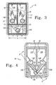
- Fig. 1 is a top perspective view of a preferred multi-chamber ink jet printhead in accordance with the present invention showing the preferred arrangement of the ink chambers;
- Fig. 2 is a bottom perspective view of the multi-chamber ink jet printhead of Fig. 1 showing the ink orifices;
- Fig. 3 is a top plan view of the multi-chamber ink jet printhead of Fig. 1 showing the preferred arrangement of the ink ports;
- Fig. 4 is a bottom cross-sectional view along line 4-4 of Fig. 1 showing the preferred arrangement of the ink ports and ink channels;
- Fig. 5 is a view from underneath the multi-chamber ink jet printhead of Fig. 1 showing the ink orifices; and
- Fig. 6 is a cross-sectional view along line 6-6 of Fig. 4 showing two ink chambers and corresponding ports.
-
- Reference is now made to Fig. 1 illustrating a preferred multi-chamber ink jet printhead cartridge in accordance with the present invention generally indicated by the
reference numeral 10. Theprinthead cartridge 10 comprises more than two ink chambers 12. More preferably, it comprises threeink chambers 12A-C. As will become apparent by reviewing the description below, the multi-chamber inkjet printhead cartridge 10 provides an effective means for maximizing the overall volume and ink storage capability of thecartridge 10 while minimizing the footprint or total space occupied by theprint cartridge 10. - The cartridge can be moulded by any method known in the art, including injection moulding, compression moulding, transfer moulding or thermoforming. Preferably it is injection moulded from an engineering thermoplastic. Suitable thermoplastics include, but are not limited to, polyesters, polycarbonates, polypropylenes, polyethylenes and modified polyphenylene oxides (PPO) and blends thereof. The thermoplastics may be filled or unfilled. Suitable fillers can include, but are not limited to minerals, glass or graphite. Preferably, the cartridge is moulded from an unfilled, modified PPO, such as is available from the General Electric Company of Pittsfield, Massachusetts under the trade name Noryl®. More preferably, the cartridge is moulded from Noryl® SE1-701. Features of the
cartridge 10, such as exit ports and chambers can be machined into the moulded cartridge or bonded onto the cartridge in a secondary operation. Preferably, all features are moulded into the cartridge. - As shown in Fig. 1,
typical ink chambers 12A-C have a length L and a width W. Preferably, in the ink chambers, the length L is greater than the width W such that theink chambers 12A-C each have a substantially rectangular shape. However, ink chambers may be substantially square in shape, i.e., the L and W dimensions are about equal to one another. Eachchamber 12A-C may have different L dimensions and different W dimensions from those of the other chambers. Preferably, at least two of thechambers 12A-C have substantially the same L dimensions and substantially the same W dimensions. More preferably, all chambers in theink jet printhead 10 have substantially equivalent L dimensions and substantially equivalent W dimensions. Preferably,chambers 12A-C combine to form a unitary multichambered ink reservoir having a unitaryouter wall 13. - Each chamber also has a volume defined by the L and W dimensions and by a D dimension, which represents the depth of the chamber. It is preferred that each of the chambers in the
printhead 10 have substantially the same volume, even if they do not have the same L, W and D dimensions. - As best shown in Figs. 1 and 3, at least one
ink chamber 12A is preferably arranged substantially perpendicularly to and substantially adjacent with at least twoother chambers chambers chamber 12A arranged perpendicularly to the other chambers. All chambers are preferably contiguous to one another in that at least one side wall of each chamber is touching or adjacent to a side wall of another chamber. As it will be understood, this configuration advantageously allows for thecartridge 10 to be less cumbersome and of smaller dimensions than prior art cartridges without reducing the amount of ink capable of being stored therein. - As best shown in Figs. 3, 4 and 6, at the base of each
chamber corresponding exit port corresponding channel respective ink orifices channels ink orifices - The location of the
chambers 12A-C and the exit ports 14 in each chamber may be arranged so that when the chambers are arranged in theprinthead 10, the exit ports 14 are in close proximity to one another so as to minimize the overall distance between any of the ports. As it will be understood, this arrangement minimizes the distance that the ink must traverse through the channels 20 in order to reach the orifices 22. - Alternatively, and more preferably from a manufacturing perspective, the
exit port 14A is located in a central portion ofchamber 12A, andexit ports exit ports adjacent walls machining channels ports adjacent walls - In the preferred embodiment where three ink chambers are used, it is preferable that each of the two parallel chambers includes a relatively longer
central side wall 18 and a relatively shortercentral side wall 16. Additionally, the twoparallel chambers central side wall 18. Theperpendicular chamber 12A preferably includes a relatively longcentral side wall 24 as well. It should be appreciated that the two relatively shortercentral side walls 16 of theparallel chambers central side wall 24 of the perpendicular chamber. The exit ports 14 of the twoparallel chambers longer side walls 18 and relatively shortercentral side walls 16 of each parallel chamber. The exit port 14 of the perpendicular chamber is preferably located in close proximity with the relatively longcentral side wall 24 of the perpendicular chamber in the center of the L dimension of the perpendicular chamber. - More preferably, as shown in Fig. 3, the three exit ports 14 are arranged in a substantially triangular configuration wherein a line connecting a point in the center of each port would produce a triangle. The exit port in the perpendicular chamber may or may not be centrally located with respect to the W dimension of the perpendicular chamber. It may be located closer to the wall of the perpendicular chamber that abuts the parallel chambers. Preferably, the triangle formed by a line drawn through a point in the center of each exit port is an equilateral triangle.
- The orifices 22 of the
ink jet printhead 10 can be located anywhere in the printhead. However, it is preferable that they be located so as to minimize the overall ink flow distance from the exit ports 14 through the channels 20 to the orifices 22. More preferably, the orifices 22 are located on the base of the printhead cartridge 10 (see Figs. 2, 5 and 6) in close proximity to the exit port 14 of the perpendicular chamber. However, there is no limitation as to the location of the orifices. As shown in Fig. 5, all orifices preferably touch or overlap aline 26 bisecting the cartridge from front to back. - In summary, numerous benefits have been described which result from employing the concepts of the invention. The multi-chamber
ink jet printhead 10 of the present invention can be made less cumbersome than the prior art multi-chamber ink jet cartridges and is therefore characterized by a relatively large overall ink storage volume within thechambers 12A-C and a relatively small footprint, or total space, occupied by theprinthead cartridge 10. Additionally, the inkjet printhead cartridge 10 may include ink output ports arranged so as to reduce the distance the various inks must flow to reach corresponding output orifices. Finally, the multi-chamber liquidink jet printhead 10 is capable of being used on existing as well as later-developed ink jet printers.
Claims (26)
- A multi-chamber ink jet printhead cartridge comprising a plurality of ink chambers (12A, 12B, 12C), each ink chamber having an exit port (14A, 14B, 14C), and said each ink chamber having a length and a width, the length of each said ink chamber being greater than the width, wherein at least one perpendicular chamber (12A) is arranged such that the length of said at least one perpendicular chamber is substantially perpendicular to the lengths of at least two other chambers (12B, 12C), and said at least one perpendicular chamber is substantially adjacent with said at least two other chambers, wherein said plurality of chambers comprises three ink chambers, said three ink chambers being a first parallel chamber, a second parallel chamber and a perpendicular chamber, the length of said first parallel chamber being parallel to the length of said second parallel chamber, and the length of said perpendicular chamber being perpendicular to the lengths of said first and second parallel chambers, wherein said first and second parallel chambers each comprise a relatively shorter central side wall (16) that substantially abuts a relatively longer central side wall (18) of said perpendicular chamber, each of said first and second parallel chambers further comprising a relatively longer central side wall, the relatively longer central side wall of said first parallel chamber substantially abutting the relatively longer central side wall of said second parallel chamber, said exit port (14B, 14C) of each of said first and second parallel chambers being further disposed in close proximity with said relatively shorter and said relatively longer central side walls of said first and second parallel chambers, said exit port (14A) of said perpendicular chamber being disposed close to a midpoint of said relatively longer central side wall of said perpendicular chamber.
- The ink jet printhead cartridge of claim 1 wherein at least two of said chambers (12B, 12C) have substantially equivalent widths (W), and wherein at least two of said chambers (12B, 12C) have substantially equivalent lengths (L).
- The ink jet printhead cartridge of claim 1 or 2, wherein said chambers (12A, 12B, 12C) are substantially rectangular.
- The ink jet printhead cartridge of claim 1, 2 or 3, wherein each chamber (12A, 12B, 12C) of said plurality of chambers is of substantially the same volume.
- The ink jet printhead cartridge of any preceding claim, wherein said plurality of chambers (12A, 12B, 12C) comprises at least two parallel chambers (12B, 12C) disposed side-by-side in a parallel relationship.
- The ink jet printhead cartridge of any preceding claim, wherein each chamber (12A, 12B, 12C) of said plurality of chambers have substantially equivalent widths (W), and wherein each chamber of said plurality of chambers have substantially equivalent lengths (L) of substantially the same width and length.
- The ink jet printhead cartridge of any preceding claim, wherein said exit ports (14A, 14B, 14C) are connected by corresponding flow channels (20A, 20B, 20C) to ink-dispensing orifices (22A, 22B, 22C).
- The ink jet printhead cartridge of claim 7, wherein said orifices (22A,22B, 22C) are located on a base portion of the cartridge in close proximity with the exit port (14A) of the perpendicular chamber (12A).
- The ink jet printhead cartridge of claim 7 or 8, wherein the orifices (22A, 22B, 22C) touch a line (26) bisecting the perpendicular chamber (12A).
- The ink jet printhead cartridge of any preceding claim, wherein a group of exit ports (14A, 14B, 14C) is arranged in a triangular configuration.
- The ink jet printhead cartridge of any preceding claim, wherein the exit port of each chamber is located so as to minimize the distance between the ports.
- A multi-chamber ink jet printhead cartridge comprising a plurality of ink chambers (12A, 12B, 12C), each ink chamber having an exit port (14A, 14B, 14C), wherein at least one chamber (12A) is arranged substantially perpendicular to and substantially adjacent with at least two other chambers (12B, 12C).
- The ink jet printhead cartridge of claim 12 wherein at least two of said chambers (12B, 12C) have substantially equivalent widths (W), and wherein at least two of said chambers (12B, 12C), have substantially equivalent lengths (L).
- The ink jet printhead cartridge of claim 12 or 13, wherein said chambers (12A, 12B, 12C) are substantially rectangular.
- The ink jet printhead cartridge of claim 12, 13 or 14, wherein each chamber (12A, 12B, 12C) of said plurality of chambers is of substantially the same volume.
- The ink jet printhead cartridge of any of claims 12 to 15, wherein said plurality of chambers (12A, 12B, 12C) comprises three ink chambers.
- The ink jet printhead cartridge of any of claims 12 to 16, wherein said plurality of chambers (12A, 12B, 12C) comprises at least two parallel chambers (12B, 12C) disposed side-by-side in a parallel relationship.
- The ink jet printhead cartridge of claim 17, wherein said parallel chambers (12B, 12C) each comprise a relatively shorter central side wall (16) that substantially abuts a relatively longer central side wall (24) of the perpendicular chamber (12A), each said parallel chamber further comprising a relatively longer central side wall (18) that substantially abuts the relatively longer central side wall (18) if the other parallel chamber, each exit port (14B, 14C) of each parallel chamber being further disposed in close proximity with said relatively shorter and said relatively longer side walls (16, 18) of the parallel chamber, said exit port (14A) of the perpendicular chamber (12A) being disposed in close proximity with said relatively longer central side wall (24) of said perpendicular chamber.
- The ink jet printhead cartridge of claim 18, wherein the exit port (14A) of the perpendicular chamber (12A) is disposed close to a midpoint of the central side wall (24) of the perpendicular chamber.
- The ink jet printhead cartridge of any of claims 12 to 19, wherein each chamber (12A, 12B, 12C) of said plurality of chambers have substantially equivalent widths (W), and wherein each chamber of said plurality of chambers have substantially equivalent lengths (L), of substantially the same width and length.
- The ink jet printhead cartridge of any of claims 12 to 20, wherein said exit ports (14A, 14B, 14C) are connected by corresponding flow channels (20A, 20B, 20C) to ink-dispensing orifices (22A, 22B, 22C).
- The ink jet printhead cartridge of claim 21, wherein said orifices (22A, 22B, 22C) are located on a base portion of the cartridge in close proximity with the exit port (14A) of the perpendicular chamber (12A).
- The ink jet printhead cartridge of claim 21 or 22, wherein the orifices (22A, 22B,22C) touch a line (26) bisecting the perpendicular chamber (12A).
- The ink jet printhead cartridge of any of claims 12 to 23, wherein a group of exit ports (14A, 14B, 14C) is arranged in a triangular configuration.
- The ink jet printhead cartridge of any of claims 12 to 24, wherein the exit port of each chamber is located so as to minimise the distance between the ports.
- An ink jet cartridge comprising a unitary reservoir having an outer wall (13) and at least two inner walls (16, 18, 24) which define three ink chambers (12A, 12B, 12C) therein, wherein at least one exit port (14A, 14B, 14C) is associated with each of said three ink chambers, wherein the exit ports are arranged in a triangular configuration, and wherein the exit ports (14B, 14C) of each of two chambers (12B, 12C) is located substantially adjacent said outer wall and substantially adjacent at least one of said two inner walls.
Applications Claiming Priority (3)
| Application Number | Priority Date | Filing Date | Title |
|---|---|---|---|
| US755520 | 1996-11-22 | ||
| US08/755,520 US5926195A (en) | 1996-11-22 | 1996-11-22 | Ink jet printhead cartridge |
| EP97309453A EP0845363B1 (en) | 1996-11-22 | 1997-11-24 | Ink jet printhead cartridge |
Related Parent Applications (1)
| Application Number | Title | Priority Date | Filing Date |
|---|---|---|---|
| EP97309453A Division EP0845363B1 (en) | 1996-11-22 | 1997-11-24 | Ink jet printhead cartridge |
Publications (2)
| Publication Number | Publication Date |
|---|---|
| EP1510349A1 true EP1510349A1 (en) | 2005-03-02 |
| EP1510349B1 EP1510349B1 (en) | 2007-04-18 |
Family
ID=25039496
Family Applications (2)
| Application Number | Title | Priority Date | Filing Date |
|---|---|---|---|
| EP04023804A Expired - Lifetime EP1510349B1 (en) | 1996-11-22 | 1997-11-24 | Ink jet printhead cartridge |
| EP97309453A Expired - Lifetime EP0845363B1 (en) | 1996-11-22 | 1997-11-24 | Ink jet printhead cartridge |
Family Applications After (1)
| Application Number | Title | Priority Date | Filing Date |
|---|---|---|---|
| EP97309453A Expired - Lifetime EP0845363B1 (en) | 1996-11-22 | 1997-11-24 | Ink jet printhead cartridge |
Country Status (6)
| Country | Link |
|---|---|
| US (1) | US5926195A (en) |
| EP (2) | EP1510349B1 (en) |
| JP (1) | JPH10181036A (en) |
| AU (1) | AU720342B2 (en) |
| DE (2) | DE69737640T2 (en) |
| HK (1) | HK1076775A1 (en) |
Families Citing this family (28)
| Publication number | Priority date | Publication date | Assignee | Title |
|---|---|---|---|---|
| US6705705B2 (en) * | 1998-12-17 | 2004-03-16 | Hewlett-Packard Development Company, L.P. | Substrate for fluid ejection devices |
| US7048375B2 (en) * | 1999-11-01 | 2006-05-23 | Praful Doshi | Tinted lenses and methods of manufacture |
| US7267846B2 (en) * | 1999-11-01 | 2007-09-11 | Praful Doshi | Tinted lenses and methods of manufacture |
| DE60025539T2 (en) | 1999-11-01 | 2006-07-27 | Praful Poway Doshi | TINTED CONTACT LENS IN PLASTIC AND METHOD FOR THE PRODUCTION THEREOF |
| US6290348B1 (en) * | 2000-01-05 | 2001-09-18 | Hewlett-Packard Company | Techniques for providing ink-jet cartridges with a universal body structure |
| US6811259B2 (en) * | 2000-06-12 | 2004-11-02 | Novartis Ag | Printing colored contact lenses |
| US20030085934A1 (en) | 2001-11-07 | 2003-05-08 | Tucker Robert Carey | Ink-jet printing system for printing colored images on contact lenses |
| US7411008B2 (en) * | 2001-11-07 | 2008-08-12 | Novartis Ag | Ink formulations and uses thereof |
| US6893120B2 (en) * | 2002-11-19 | 2005-05-17 | Lexmark International, Inc. | Multi-color ink reservoirs for ink jet printers |
| KR100503082B1 (en) | 2003-01-03 | 2005-07-21 | 삼성전자주식회사 | Ink cartridge for ink jet printer |
| ATE409589T1 (en) * | 2003-01-22 | 2008-10-15 | Microjet Technology Co Ltd | STRUCTURE OF AN INK JET CARTRIDGE AND METHOD FOR PRODUCING IT |
| US6840609B2 (en) * | 2003-02-05 | 2005-01-11 | Microjet Technology, Ltd. | Structure of ink cartridge and method for producing the same |
| TW577823B (en) * | 2003-04-09 | 2004-03-01 | Benq Corp | Ink-jet cartridge |
| US6851800B1 (en) | 2003-07-29 | 2005-02-08 | Hewlett-Packard Development Company, L.P. | Print cartridge bodies |
| KR100571776B1 (en) * | 2004-02-06 | 2006-04-18 | 삼성전자주식회사 | Ink cartridge |
| US20050183629A1 (en) * | 2004-02-20 | 2005-08-25 | Mccain Sandra H. | Pigment black and dilute dye inks in ink set |
| CN100340408C (en) * | 2004-04-01 | 2007-10-03 | 国际联合科技股份有限公司 | Ink box |
| US20060001711A1 (en) * | 2004-06-30 | 2006-01-05 | Lexmark International, Inc. | Inkjet printhead with multiple ink reservoirs |
| US7201476B2 (en) * | 2004-12-10 | 2007-04-10 | Lexmark International, Inc. | Inkjet printhead with bubble handling properties |
| JP4683614B2 (en) * | 2004-12-17 | 2011-05-18 | キヤノン株式会社 | Inkjet cartridge |
| US20070058011A1 (en) * | 2005-09-12 | 2007-03-15 | Christopher Waclaw Wencel | Method of cleaning an inkjet cartridge |
| TWI284601B (en) * | 2006-05-19 | 2007-08-01 | Int United Technology Co Ltd | Ink cartidge |
| US7712883B2 (en) * | 2006-07-26 | 2010-05-11 | Hewlett-Packard Development Company, L.P. | Print cartridge body |
| GB2451280A (en) * | 2007-07-26 | 2009-01-28 | Hewlett Packard Development Co | Colour print cartridge having a single block of hydrophobic foam material |
| US8857960B2 (en) | 2011-10-28 | 2014-10-14 | Hewlett-Packard Development Company, L.P. | Fluid supply housing |
| US9815290B2 (en) * | 2014-01-30 | 2017-11-14 | Hewlett-Packard Development Company, L.P. | Tri-color ink cartridge |
| CN105939863B (en) | 2014-01-30 | 2018-06-15 | 惠普发展公司,有限责任合伙企业 | Three-colour ink cartridge housing |
| US11577250B2 (en) * | 2021-01-20 | 2023-02-14 | Funai Electric Co. Ltd | Pipette-fillable cartridge |
Citations (10)
| Publication number | Priority date | Publication date | Assignee | Title |
|---|---|---|---|---|
| US4513296A (en) | 1982-02-06 | 1985-04-23 | Fuji Xerox Co., Ltd. | Heat-sensitive recording head |
| DE3424175A1 (en) * | 1984-06-30 | 1986-01-09 | Olympia Werke Ag, 2940 Wilhelmshaven | Ink cartridge for an inking apparatus for multicolour printing on a recording medium |
| US4812859A (en) | 1987-09-17 | 1989-03-14 | Hewlett-Packard Company | Multi-chamber ink jet recording head for color use |
| EP0529879A1 (en) * | 1991-08-29 | 1993-03-03 | Hewlett-Packard Company | Leak resistant ink-jet pen |
| EP0655336A1 (en) * | 1993-11-29 | 1995-05-31 | Canon Kabushiki Kaisha | Improved ink container, installing-removing method therefore, and apparatus usable with the same |
| EP0657292A1 (en) * | 1993-12-10 | 1995-06-14 | Lexmark International, Inc. | Multicolor liquid ink jet print head |
| EP0677389A1 (en) * | 1993-09-29 | 1995-10-18 | Canon Kabushiki Kaisha | Ink jet head and ink jet apparatus provided with the same |
| EP0699532A2 (en) * | 1994-08-31 | 1996-03-06 | Canon Kabushiki Kaisha | Ink jet refilling method and apparatus for ink container |
| EP0713778A2 (en) * | 1994-11-22 | 1996-05-29 | Lexmark International, Inc. | Venting device for ink cartridge |
| EP0748692A1 (en) * | 1995-06-13 | 1996-12-18 | Canon Kabushiki Kaisha | Ink container, manufacturing method therefor, ink jet cartridge and ink jet apparatus |
Family Cites Families (4)
| Publication number | Priority date | Publication date | Assignee | Title |
|---|---|---|---|---|
| JPS58205773A (en) * | 1982-05-27 | 1983-11-30 | Canon Inc | Ink jet printer |
| US5025271A (en) * | 1986-07-01 | 1991-06-18 | Hewlett-Packard Company | Thin film resistor type thermal ink pen using a form storage ink supply |
| JPH02188249A (en) * | 1989-01-18 | 1990-07-24 | Canon Inc | Liquid jet recording head, holder for scanning same head, and liquid jet recorder using same means |
| JP3027505B2 (en) * | 1994-04-20 | 2000-04-04 | キタムラ機械株式会社 | Spindle device |
-
1996
- 1996-11-22 US US08/755,520 patent/US5926195A/en not_active Expired - Lifetime
-
1997
- 1997-10-21 AU AU42808/97A patent/AU720342B2/en not_active Ceased
- 1997-11-21 JP JP9337796A patent/JPH10181036A/en active Pending
- 1997-11-24 EP EP04023804A patent/EP1510349B1/en not_active Expired - Lifetime
- 1997-11-24 DE DE69737640T patent/DE69737640T2/en not_active Expired - Lifetime
- 1997-11-24 EP EP97309453A patent/EP0845363B1/en not_active Expired - Lifetime
- 1997-11-24 DE DE69731165T patent/DE69731165T2/en not_active Expired - Lifetime
-
2005
- 2005-09-02 HK HK05107739A patent/HK1076775A1/en not_active IP Right Cessation
Patent Citations (10)
| Publication number | Priority date | Publication date | Assignee | Title |
|---|---|---|---|---|
| US4513296A (en) | 1982-02-06 | 1985-04-23 | Fuji Xerox Co., Ltd. | Heat-sensitive recording head |
| DE3424175A1 (en) * | 1984-06-30 | 1986-01-09 | Olympia Werke Ag, 2940 Wilhelmshaven | Ink cartridge for an inking apparatus for multicolour printing on a recording medium |
| US4812859A (en) | 1987-09-17 | 1989-03-14 | Hewlett-Packard Company | Multi-chamber ink jet recording head for color use |
| EP0529879A1 (en) * | 1991-08-29 | 1993-03-03 | Hewlett-Packard Company | Leak resistant ink-jet pen |
| EP0677389A1 (en) * | 1993-09-29 | 1995-10-18 | Canon Kabushiki Kaisha | Ink jet head and ink jet apparatus provided with the same |
| EP0655336A1 (en) * | 1993-11-29 | 1995-05-31 | Canon Kabushiki Kaisha | Improved ink container, installing-removing method therefore, and apparatus usable with the same |
| EP0657292A1 (en) * | 1993-12-10 | 1995-06-14 | Lexmark International, Inc. | Multicolor liquid ink jet print head |
| EP0699532A2 (en) * | 1994-08-31 | 1996-03-06 | Canon Kabushiki Kaisha | Ink jet refilling method and apparatus for ink container |
| EP0713778A2 (en) * | 1994-11-22 | 1996-05-29 | Lexmark International, Inc. | Venting device for ink cartridge |
| EP0748692A1 (en) * | 1995-06-13 | 1996-12-18 | Canon Kabushiki Kaisha | Ink container, manufacturing method therefor, ink jet cartridge and ink jet apparatus |
Also Published As
| Publication number | Publication date |
|---|---|
| DE69737640D1 (en) | 2007-05-31 |
| JPH10181036A (en) | 1998-07-07 |
| US5926195A (en) | 1999-07-20 |
| DE69731165D1 (en) | 2004-11-18 |
| EP0845363A2 (en) | 1998-06-03 |
| DE69737640T2 (en) | 2008-01-03 |
| EP1510349B1 (en) | 2007-04-18 |
| AU720342B2 (en) | 2000-05-25 |
| EP0845363A3 (en) | 2000-01-19 |
| AU4280897A (en) | 1998-05-28 |
| HK1076775A1 (en) | 2006-01-27 |
| EP0845363B1 (en) | 2004-10-13 |
| DE69731165T2 (en) | 2005-10-13 |
Similar Documents
| Publication | Publication Date | Title |
|---|---|---|
| EP0845363B1 (en) | Ink jet printhead cartridge | |
| US5576750A (en) | Reliable connecting pathways for a three-color ink-jet cartridge | |
| US4942409A (en) | Drop-on-demand printhead | |
| US5432540A (en) | Ink jet head | |
| EP0657292B1 (en) | Multicolor liquid ink jet print head | |
| IL160263A (en) | Ink distribution assembly for an ink jet printhead | |
| US5602574A (en) | Matrix pen arrangement for inkjet printing | |
| US20040223031A1 (en) | Ink distribution assembly for an ink jet printhead | |
| US5815185A (en) | Ink flow heat exchanger for inkjet printhead | |
| US5402162A (en) | Integrated multi-color ink jet printhead | |
| US8132900B2 (en) | Inkjet recording head cartridge | |
| EP0755791B1 (en) | Actuator unit for an ink jet recording head and method of fabricating same | |
| US6652068B2 (en) | Compact printhead and method of delivering ink to the printhead | |
| US6543887B2 (en) | Inkjet print head | |
| US7448740B2 (en) | Inkjet cartridge | |
| US10569543B2 (en) | Printhead assembly module | |
| EP3512688A1 (en) | Fluid ejection devices to dispense fluid of different sizes | |
| US8733893B2 (en) | Multi-member, nested printhead | |
| EP0694397A2 (en) | Ink jet head and ink jet apparatus on which the ink jet head is mounted | |
| GB2288765A (en) | Shear-mode ink-jet print head. | |
| US20020118257A1 (en) | printhead employing both slotted and edgefeed fluid delivery to firing resistors | |
| JPH08290585A (en) | Ink reservoir and ink jet recorder using the same | |
| WO1998009819A1 (en) | Ink jet printer | |
| JPH04305463A (en) | Electronic apparatus using ink jet recorder |
Legal Events
| Date | Code | Title | Description |
|---|---|---|---|
| PUAI | Public reference made under article 153(3) epc to a published international application that has entered the european phase |
Free format text: ORIGINAL CODE: 0009012 |
|
| AC | Divisional application: reference to earlier application |
Ref document number: 0845363 Country of ref document: EP Kind code of ref document: P |
|
| AK | Designated contracting states |
Kind code of ref document: A1 Designated state(s): DE FR GB IT |
|
| 17P | Request for examination filed |
Effective date: 20050228 |
|
| AKX | Designation fees paid |
Designated state(s): DE FR GB IT |
|
| REG | Reference to a national code |
Ref country code: HK Ref legal event code: DE Ref document number: 1076775 Country of ref document: HK |
|
| GRAP | Despatch of communication of intention to grant a patent |
Free format text: ORIGINAL CODE: EPIDOSNIGR1 |
|
| GRAS | Grant fee paid |
Free format text: ORIGINAL CODE: EPIDOSNIGR3 |
|
| GRAA | (expected) grant |
Free format text: ORIGINAL CODE: 0009210 |
|
| AC | Divisional application: reference to earlier application |
Ref document number: 0845363 Country of ref document: EP Kind code of ref document: P |
|
| AK | Designated contracting states |
Kind code of ref document: B1 Designated state(s): DE FR GB IT |
|
| REF | Corresponds to: |
Ref document number: 69737640 Country of ref document: DE Date of ref document: 20070531 Kind code of ref document: P |
|
| ET | Fr: translation filed | ||
| PLBE | No opposition filed within time limit |
Free format text: ORIGINAL CODE: 0009261 |
|
| STAA | Information on the status of an ep patent application or granted ep patent |
Free format text: STATUS: NO OPPOSITION FILED WITHIN TIME LIMIT |
|
| 26N | No opposition filed |
Effective date: 20080121 |
|
| REG | Reference to a national code |
Ref country code: HK Ref legal event code: GR Ref document number: 1076775 Country of ref document: HK |
|
| REG | Reference to a national code |
Ref country code: GB Ref legal event code: 732E Free format text: REGISTERED BETWEEN 20131107 AND 20131113 |
|
| REG | Reference to a national code |
Ref country code: DE Ref legal event code: R082 Ref document number: 69737640 Country of ref document: DE Representative=s name: ABITZ & PARTNER, DE Effective date: 20131107 Ref country code: DE Ref legal event code: R081 Ref document number: 69737640 Country of ref document: DE Owner name: FUNAI ELECTRIC CO., LTD, JP Free format text: FORMER OWNER: LEXMARK INTERNATIONAL, INC., LEXINGTON, US Effective date: 20131107 Ref country code: DE Ref legal event code: R081 Ref document number: 69737640 Country of ref document: DE Owner name: FUNAI ELECTRIC CO., LTD, DAITO CITY, JP Free format text: FORMER OWNER: LEXMARK INTERNATIONAL, INC., LEXINGTON, KY., US Effective date: 20131107 Ref country code: DE Ref legal event code: R082 Ref document number: 69737640 Country of ref document: DE Representative=s name: ABITZ & PARTNER PATENTANWAELTE MBB, DE Effective date: 20131107 |
|
| REG | Reference to a national code |
Ref country code: FR Ref legal event code: TP Owner name: FUNAI ELECTRIC CO LTD, JP Effective date: 20140102 |
|
| REG | Reference to a national code |
Ref country code: FR Ref legal event code: PLFP Year of fee payment: 19 |
|
| PGFP | Annual fee paid to national office [announced via postgrant information from national office to epo] |
Ref country code: GB Payment date: 20151118 Year of fee payment: 19 Ref country code: IT Payment date: 20151124 Year of fee payment: 19 |
|
| PGFP | Annual fee paid to national office [announced via postgrant information from national office to epo] |
Ref country code: FR Payment date: 20151008 Year of fee payment: 19 |
|
| PGFP | Annual fee paid to national office [announced via postgrant information from national office to epo] |
Ref country code: DE Payment date: 20161116 Year of fee payment: 20 |
|
| GBPC | Gb: european patent ceased through non-payment of renewal fee |
Effective date: 20161124 |
|
| REG | Reference to a national code |
Ref country code: FR Ref legal event code: ST Effective date: 20170731 |
|
| PG25 | Lapsed in a contracting state [announced via postgrant information from national office to epo] |
Ref country code: FR Free format text: LAPSE BECAUSE OF NON-PAYMENT OF DUE FEES Effective date: 20161130 Ref country code: IT Free format text: LAPSE BECAUSE OF NON-PAYMENT OF DUE FEES Effective date: 20161124 |
|
| REG | Reference to a national code |
Ref country code: DE Ref legal event code: R071 Ref document number: 69737640 Country of ref document: DE |
|
| PG25 | Lapsed in a contracting state [announced via postgrant information from national office to epo] |
Ref country code: GB Free format text: LAPSE BECAUSE OF NON-PAYMENT OF DUE FEES Effective date: 20161124 |