EP1510180A2 - Steerable loop structure - Google Patents
Steerable loop structure Download PDFInfo
- Publication number
- EP1510180A2 EP1510180A2 EP04028757A EP04028757A EP1510180A2 EP 1510180 A2 EP1510180 A2 EP 1510180A2 EP 04028757 A EP04028757 A EP 04028757A EP 04028757 A EP04028757 A EP 04028757A EP 1510180 A2 EP1510180 A2 EP 1510180A2
- Authority
- EP
- European Patent Office
- Prior art keywords
- elongate body
- probe
- distal
- catheter
- steering
- Prior art date
- Legal status (The legal status is an assumption and is not a legal conclusion. Google has not performed a legal analysis and makes no representation as to the accuracy of the status listed.)
- Granted
Links
Images

Classifications
-
- A—HUMAN NECESSITIES
- A61—MEDICAL OR VETERINARY SCIENCE; HYGIENE
- A61B—DIAGNOSIS; SURGERY; IDENTIFICATION
- A61B18/00—Surgical instruments, devices or methods for transferring non-mechanical forms of energy to or from the body
- A61B18/04—Surgical instruments, devices or methods for transferring non-mechanical forms of energy to or from the body by heating
- A61B18/12—Surgical instruments, devices or methods for transferring non-mechanical forms of energy to or from the body by heating by passing a current through the tissue to be heated, e.g. high-frequency current
- A61B18/14—Probes or electrodes therefor
- A61B18/1492—Probes or electrodes therefor having a flexible, catheter-like structure, e.g. for heart ablation
-
- A—HUMAN NECESSITIES
- A61—MEDICAL OR VETERINARY SCIENCE; HYGIENE
- A61B—DIAGNOSIS; SURGERY; IDENTIFICATION
- A61B17/00—Surgical instruments, devices or methods, e.g. tourniquets
- A61B17/00234—Surgical instruments, devices or methods, e.g. tourniquets for minimally invasive surgery
- A61B2017/00292—Surgical instruments, devices or methods, e.g. tourniquets for minimally invasive surgery mounted on or guided by flexible, e.g. catheter-like, means
- A61B2017/003—Steerable
-
- A—HUMAN NECESSITIES
- A61—MEDICAL OR VETERINARY SCIENCE; HYGIENE
- A61B—DIAGNOSIS; SURGERY; IDENTIFICATION
- A61B18/00—Surgical instruments, devices or methods for transferring non-mechanical forms of energy to or from the body
- A61B2018/00053—Mechanical features of the instrument of device
- A61B2018/00107—Coatings on the energy applicator
- A61B2018/00148—Coatings on the energy applicator with metal
-
- A—HUMAN NECESSITIES
- A61—MEDICAL OR VETERINARY SCIENCE; HYGIENE
- A61B—DIAGNOSIS; SURGERY; IDENTIFICATION
- A61B18/00—Surgical instruments, devices or methods for transferring non-mechanical forms of energy to or from the body
- A61B2018/00053—Mechanical features of the instrument of device
- A61B2018/00214—Expandable means emitting energy, e.g. by elements carried thereon
-
- A—HUMAN NECESSITIES
- A61—MEDICAL OR VETERINARY SCIENCE; HYGIENE
- A61B—DIAGNOSIS; SURGERY; IDENTIFICATION
- A61B18/00—Surgical instruments, devices or methods for transferring non-mechanical forms of energy to or from the body
- A61B2018/00636—Sensing and controlling the application of energy
- A61B2018/00773—Sensed parameters
- A61B2018/00791—Temperature
- A61B2018/00797—Temperature measured by multiple temperature sensors
-
- A—HUMAN NECESSITIES
- A61—MEDICAL OR VETERINARY SCIENCE; HYGIENE
- A61B—DIAGNOSIS; SURGERY; IDENTIFICATION
- A61B18/00—Surgical instruments, devices or methods for transferring non-mechanical forms of energy to or from the body
- A61B2018/00636—Sensing and controlling the application of energy
- A61B2018/00898—Alarms or notifications created in response to an abnormal condition
-
- A—HUMAN NECESSITIES
- A61—MEDICAL OR VETERINARY SCIENCE; HYGIENE
- A61B—DIAGNOSIS; SURGERY; IDENTIFICATION
- A61B18/00—Surgical instruments, devices or methods for transferring non-mechanical forms of energy to or from the body
- A61B18/04—Surgical instruments, devices or methods for transferring non-mechanical forms of energy to or from the body by heating
- A61B18/12—Surgical instruments, devices or methods for transferring non-mechanical forms of energy to or from the body by heating by passing a current through the tissue to be heated, e.g. high-frequency current
- A61B18/1206—Generators therefor
- A61B2018/1246—Generators therefor characterised by the output polarity
- A61B2018/1253—Generators therefor characterised by the output polarity monopolar
-
- A—HUMAN NECESSITIES
- A61—MEDICAL OR VETERINARY SCIENCE; HYGIENE
- A61B—DIAGNOSIS; SURGERY; IDENTIFICATION
- A61B18/00—Surgical instruments, devices or methods for transferring non-mechanical forms of energy to or from the body
- A61B18/04—Surgical instruments, devices or methods for transferring non-mechanical forms of energy to or from the body by heating
- A61B18/12—Surgical instruments, devices or methods for transferring non-mechanical forms of energy to or from the body by heating by passing a current through the tissue to be heated, e.g. high-frequency current
- A61B18/1206—Generators therefor
- A61B2018/1246—Generators therefor characterised by the output polarity
- A61B2018/126—Generators therefor characterised by the output polarity bipolar
-
- A—HUMAN NECESSITIES
- A61—MEDICAL OR VETERINARY SCIENCE; HYGIENE
- A61B—DIAGNOSIS; SURGERY; IDENTIFICATION
- A61B18/00—Surgical instruments, devices or methods for transferring non-mechanical forms of energy to or from the body
- A61B18/04—Surgical instruments, devices or methods for transferring non-mechanical forms of energy to or from the body by heating
- A61B18/12—Surgical instruments, devices or methods for transferring non-mechanical forms of energy to or from the body by heating by passing a current through the tissue to be heated, e.g. high-frequency current
- A61B18/14—Probes or electrodes therefor
- A61B2018/1405—Electrodes having a specific shape
- A61B2018/1407—Loop
- A61B2018/141—Snare
Definitions
- the present inventions relate generally to medical devices that support one or more diagnostic or therapeutic elements in contact with body tissue and, more particularly, to loop structures that support one or more diagnostic or therapeutic elements in contact with body tissue.
- arrhythmia There are many instances where diagnostic and therapeutic elements must be inserted into the body.
- One instance involves the treatment of cardiac conditions such as atrial fibrillation and atrial flutter which lead to an unpleasant, irregular heart beat, called arrhythmia.
- SA node sinoatrial node
- AV node atrioventricular node
- This propagation causes the atria to contract in an organized way to transport blood from the atria to the ventricles, and to provide timed stimulation of the ventricles.
- the AV node regulates the propagation delay to the atrioventricular bundle (or "HIS" bundle).
- HIS atrioventricular bundle
- Atrial fibrillation occurs when anatomical obstacles in the heart disrupt the normally uniform propagation of electrical impulses in the atria. These anatomical obstacles (called “conduction blocks”) can cause the electrical impulse to degenerate into several circular wavelets that circulate about the obstacles. These wavelets, called “reentry circuits,” disrupt the normally uniform activation of the left and right atria.
- One surgical method of treating atrial fibrillation by interrupting pathways for reentry circuits is the so-called "maze procedure" which relies on a prescribed pattern of incisions to anatomically create a convoluted path, or maze, for electrical propagation within the left and right atria.
- the incisions direct the electrical impulse from the SA node along a specified route through all regions of both atria, causing uniform contraction required for normal atrial transport function.
- the incisions finally direct the impulse to the AV node to activate the ventricles, restoring normal atrioventricular synchrony.
- the incisions are also carefully placed to interrupt the conduction routes of the most common reentry circuits.
- the maze procedure has been found very effective in curing atrial fibrillation. However, the maze procedure is technically difficult to do. It also requires open heart surgery and is very expensive.
- Catheters used to create lesions typically include a relatively long and relatively flexible body portion that has a soft tissue coagulation electrode on its distal end and/or a series of spaced tissue coagulation electrodes near the distal end.
- the portion of the catheter body portion that is inserted into the patient is typically from 23 to 55 inches (58.4 to 139.7 cm) in length and there may be another 8 to 15 inches (20.3 to 38.1 cm), including a handle, outside the patient.
- the length and flexibility of the catheter body allow the catheter to be inserted into a main vein or artery (typically the femoral artery), directed into the interior of the heart, and then manipulated such that the coagulation electrode contacts the tissue that is to be ablated. Fluoroscopic imaging is used to provide the physician with a visual indication of the location of the catheter.
- the proximal end of the catheter body is connected to a handle that includes steering controls.
- Exemplary catheters of this type are disclosed in U.S. Patent No. 5,582,609.
- the catheter body is inserted into the patient through a sheath and the distal portion of the catheter is bent into loop that extends outwardly from the sheath. This may be accomplished by pivotably securing the distal end of the catheter to the distal end of the sheath, as is illustrated in U.S. Patent No. 6,071,279.
- the loop is formed as the catheter is pushed in the distal direction.
- the loop may also be formed by securing a pull wire to the distal end of the catheter that extends back through the sheath, as is illustrated in U.S.
- Loop catheters are advantageous in that they tend to conform to different tissue contours and geometries and provide intimate contact between the spaced tissue coagulation electrodes (or other diagnostic or therapeutic elements) and the tissue. Loop catheters also tend to cause the atria to conform to the shape of the loop.
- the inventor herein has determined that one issue associated with conventional catheters is that, when deployed, the loop structures tend to follow the path of least resistance and occupy the largest diameter portion of the atria.
- the largest diameter portion is not, however, always the intended diagnostic or therapeutic location. This is especially true in those instances where the preferred loop position is near an atrial appendage or a ventricular annulus because conventional loop structures can slip into the atrial appendage or ventricular annulus.
- the inventor herein has determined that a need exists generally for loop structures that can be deployed within the atrium (or some other bodily structure) and, if desired, deflected in such a manner that they occupy a portion of the atrium other than the largest diameter portion.
- the general object of the present inventions is to provide a device that avoids, for practical purposes, the aforementioned problems.
- one object of the present inventions is to provide a loop structure that can, if desired, be deployed with a bodily structure in such a manner that it occupies a portion of the bodily structure other than the largest diameter portion and/or the portion associated with the path of least resistance.
- Another object of the present inventions is to provide a loop structure having at least a portion that can, if desired, be deflected.
- a probe in accordance with one embodiment of a present invention includes an elongate body that can be deployed as a loop and a steering element secured to the distal portion of the elongate body.
- the steering element may be used to deflect a portion of the loop out of the loop plane.
- Such a probe advantageously allows the physician to steer the loop into contact with intended diagnostic and therapeutic locations which the loop would not contact absent such steering.
- the steering capability may be used by a physician to move a portion of the loop away from an atrial appendage located along the path of least resistance to a more desirable location.
- the present inventions may be used within body lumens, chambers or cavities for diagnostic or therapeutic purposes in those instances where access to interior bodily regions is obtained through, for example, the vascular system or alimentary canal and without complex invasive surgical procedures.
- the inventions herein have application in the diagnosis and treatment of arrhythmia conditions within the heart.
- the inventions herein also have application in the diagnosis or treatment of ailments of the gastrointestinal tract, prostrate, brain, gall bladder, uterus, and other regions of the body.
- the present inventions are designed to produce intimate tissue contact with target substrates associated with various arrhythmias, namely atrial fibrillation, atrial flutter, and ventricular tachycardia.
- target substrates associated with various arrhythmias namely atrial fibrillation, atrial flutter, and ventricular tachycardia.
- embodiments of the present inventions which may include diagnostic and/or soft tissue coagulation electrodes, can be used to map tissue and/or create lesions in tissue that cure arrhythmias.
- the present inventions are discussed primarily in the context of catheter-based probes, the inventions are also adaptable for use with probes other than catheter-based probes.
- the structures disclosed herein may be used in conjunction with hand held surgical devices (or "surgical probes").
- the distal end of a surgical probe may be placed directly in contact with the targeted tissue area by a physician during a surgical procedure, such as open heart surgery.
- access may be obtained by way of a thoracotomy, median sternotomy, or thoracostomy.
- Exemplary surgical probes are disclosed in U.S. Patent No. 6,071,281.
- Surgical probe devices in accordance with the present inventions preferably include a handle, a relatively short shaft, and one of the distal assemblies described hereafter in the catheter context.
- the length of the shaft is about 4 inches to about 18 inches (10.2 to 45.7 cm). This is relatively short in comparison to the portion of a catheter body that is inserted into the patient (typically from 23 to 55 inches (58.4 to 139.7 cm) in length) and the additional body portion that remains outside the patient.
- the shaft is also relatively stiff. In other words, the shaft is either rigid, malleable, or somewhat flexible. A rigid shaft cannot be bent.
- a malleable shaft is a shaft that can be readily bent by the physician to a desired shape, without springing back when released, so that it will remain in that shape during the surgical procedure.
- the stiffness of a malleable shaft must be low enough to allow the shaft to be bent, but high enough to resist bending when the forces associated with a surgical procedure are applied to the shaft.
- a somewhat flexible shaft will bend and spring back when released.
- the force required to bend the shaft must be substantial.
- a catheter 10 in accordance with a preferred embodiment of a present invention includes a hollow, flexible catheter body 12 that is preferably formed from two tubular parts, or members.
- the proximal member 14 is relatively long and is attached to a handle 16, while the distal member 18, which is relatively short, carries a plurality of spaced electrodes 20 or other operative elements.
- the proximal member 14 is typically formed from a biocompatible thermoplastic material, such as a Pebax® material (polyether block emide) and stainless steel braid composite, which has good torque transmission properties.
- an elongate guide coil (not shown) may also be provided within the proximal member 14.
- the distal member 18 is typically formed from a softer, more flexible biocompatible thermoplastic material such as unbraided Pebax® material, polyethylene, or polyurethane.
- the proximal and distal members which are about 5 French to about 9 French (1.66 mm to 3 mm) in diameter, are preferably either bonded together with an overlapping thermal bond or adhesively bonded together end to end over a sleeve in what is referred to as a "butt bond.”
- the catheter 10 is used in combination with a sheath 22, which preferably has a greater inherent stiffness than the distal region of the catheter 12 (i.e. the distal member 18, the electrodes 20 and a spline 32 that is discussed below with reference to Figures 4 and 5).
- the sheath 22 should also be lubricious to reduce friction during movement of the catheter body 12.
- the sheath 14 is preferably a Pebax® and stainless steel braid composite. Other materials, such as polytetrafluoroethylene (PTFE), can also be used.
- the wall thickness of the sheath 22 is preferably about 0.013 inch (3.3 mm), which will not add significantly to the overall thickness of the catheter 10.
- a handle 24, which is preferably in the form of a hemostatic connector that can be used to fix the relative positions of the catheter 12 and sheath 22, is mounted on the proximal end of the sheath.
- the distal end of the sheath 22 is perpendicular to the longitudinal axis of the sheath.
- the distal end of the sheath 22 may also be cut at an angle and tapered in a transverse direction relative to the longitudinal axis of the sheath to effect the shape loop formed by the distal region of the catheter 12.
- a pull wire 26 extends from the distal end of the catheter 12 through the sheath 22 in the exemplary embodiment illustrated in Figure 1.
- the proximal end of the pull wire 26 includes an adjustable stop/handle 28.
- the pull wire 26 is preferably a flexible, inert cable constructed from strands of metal wire material, such as Nickel Titanium (commercially available under the trade name Nitinol®) or 17-7 stainless steel, that is about 0.012 to 0.018 inch (0.30 to 0.46 mm) in diameter.
- the pull wire 26 may be formed from a flexible, inert stranded or molded plastic material.
- the pull wire 26 is also .preferably round in cross-section, although other cross-sectional configurations can be used.
- the physician deploys a loop structure 30 by advancing the catheter body 12 through the sheath 22. Once the loop structure 30 has been formed, the physician can pull on the wire 26 to decrease the exposed length of the pull wire beyond the distal end of the sheath 22. Further adjustments to the loop may be made by advancing or retracting the catheter body 12 within the sheath 22 or by putting tension on the pull wire 24. For example, a portion of the loop structure 30 my be bent out of the loop plane. This aspect of the invention is discussed in greater detail below with reference to Figures 5-9.
- the loop structure 30 can be rotated by rotating the catheter body 12 with its handle 16.
- the exemplary catheter body 12 also includes a flexible spline (or "core wire") 32.
- the flexible spline 32 is preferably a wire having a diameter of approximately 0.023 inch (0.58 mm) that is positioned inside of and passes within the length of the catheter body 12.
- the flexible spline 32 is fixedly secured to the handle 16 at the proximal end of the catheter body 12 and to a tip member 34 in the manner described below.
- the tip member 34 is in turn secured to the distal end of the catheter body 12 with adhesive.
- the flexible spline 32 is made from resilient, inert wire, such as Nitinol® material or 17-7 stainless steel. Resilient injection molded plastic can also be used.
- the exemplary spline 32 is round in cross section, although other cross sectional configurations can be used.
- the flexible spline 32 may, if desired, also have a preset curvature accomplished by thermally presetting the spline at 500°C for 8 minutes. The super-elastic properties of the material should, however, be maintained.
- the flexible spline 32 includes a flattened portion 36, which is preferably adjacent to (i.e. either just proximal to, just distal to, or aligned with) the proximal end of the distal member 18, that allows this portion of the flexible spline to be bent with less force than would otherwise be required.
- the flattened portion 36 also causes the distal member 18 to bend, and the loop structure 30 to be formed, in a flat loop plane (note the side view in Figure 1 and the top view in Figure 3).
- the thickness of the flattened portion 36 would be about 0.018 inch (0.46 mm) and the length would be about 1.75 inches (4.45 cm).
- the flexible spline 32 may also be used to anchor the pull wire 26. As illustrated for example in Figure 2, the distal end 38 of the flexible spline 32 is fixedly engaged in an in-line manner to the end 40 of the pull wire 26 with a stainless steel crimp tube 42.
- the in-line connection of the flexible spline 32 and pull wire 26 allows for a reduction in the overall diameter of distal portion of the catheter body 12. This provides a significant clinical advantage over devices having side by side pull wire connections which create a larger diameter device.
- the pull wire 26 passes through a pull wire bore 44 in the catheter tip member 24 and through a bore 46 in the distal end of the crimp tube 42.
- the tip member 34 is preferably formed from platinum-iridium (90/10) and is fixedly engaged with, for example, silver solder, adhesive or spot welding, to the distal end of crimp tube 42.
- the flexible spline 32 is preferably electrically insulated with a thin walled polyester heat shrink tube 48 that extends beyond the proximal end of the crimp tube 42.
- Other pull wire configurations, other methods of attaching the pull wire to the catheter body, and methods of reducing stress on the pull wire are disclosed in U.S. Patent No. 6,048,329.
- the exemplary catheter 10 present also includes a loop deflection system that allows the physician to steer a portion 50 of the loop structure 30 out of the loop plane in the manner illustrated in Figures 6 and 7.
- the steering capability may, for example, be provided through the use of one or more steering wires.
- the exemplary catheter 10 includes a pair of steering wires 52a and 52b which pass through the heat shrink tube 48 and are secured to the flexible spline 32 with a crimp joint, solder, adhesive or other suitable instrumentalities.
- Steering wires 52a and 52b extend proximally to the exemplary handle 16, which includes handle body 54 and a steering assembly 56 that consists of a cam wheel 58 and a lever 60.
- the proximal ends of each of the steering wires 52a and 52b are secured to a cam wheel 58.
- the steering of portion 50 may be facilitated by forming a second flattened portion 62 in the spline 32 just proximally of the point at which the steering wires 52a and 52b are attached to the spline.
- the second flattened portion 62 which is rotated 90 degrees relative to the flattened portion 36, facilitates the steering of portion 50 by giving the bend directionality and creating a live hinge.
- the thickness of the second flattened portion 62 would be about 0.010 inch (0.25 mm) and the length would be about 0.50 inch (1.27 cm).
- Steerable portion 50' is larger than the steerable portion 50 illustrated in Figures 6 and 7 because the second flattened portion (not shown) in the embodiment illustrated in Figure 8 and 9 is longer than the second flattened portion 62 illustrated in Figure 5.
- a suitable length for the second flattened portion 62 in an embodiment where the flexible spline 32 has a diameter of approximately 0.023 inch (0.58 mm) would be about 1.5 inches (3.81 cm).
- the present inventions are also applicable to loop catheters in which the distal portion of catheter body is connected to the distal portion of the sheath.
- the exemplary catheter 64 does not include a pull wire and instead is used in combination with a sheath 66 which has a distal member 68 that is connected to the distal end of the catheter 64.
- a slot is formed in the distal portion of the sheath 66 and the remnant 70 forms a flexible joint.
- a stiffening element 72 may also be provided.
- the loop 74 is formed when the catheter 64 is urged distally relative to the sheath 66, thereby causing the distal portion of the catheter to bulge outwardly in the manner illustrated in Figure 10.
- exemplary catheter 64 also includes the loop steering elements described above.
- loop steering elements described above may also be used in other loop catheters where the distal portion of catheter body is connected to the distal portion of the sheath.
- One example is a catheter wherein the distal end of the catheter body is connected to the distal end of a sheath by a short wire. This and other examples of such loop catheters are disclosed in U.S. Patent No. 6,071,274.
- the steering wires 52a and 52b may be secured at respective points on the exterior of the catheter and then directed to respective points that are on the opposite side of the catheter.
- Such an arrangement provides more steering torque than would be realized if the steering wires were simply allowed to extend proximally from their attachment point in the manner illustrated in Figure 5 because the present arrangement increases the effective lever length.
- This arrangement is also applicable to steerable catheters that are not adapted to be bent into loops as well as catheters with a single steering wire, whether adapted to be bent into a loop or not.
- the exemplary catheter 84 illustrated in Figures 11-15 is in many respects identical to the catheter 10 illustrated in Figures 1-7.
- the steering wires 52a and 52b are not secured to the spline 32.
- the steering wires 52a and 52b are instead directed through steering wire lumens 86a and 86b which are formed in the distal member 18'.
- the steering wire lumens 86a and 86b which include respective inlets 88a and 88b and outlets 90a and 90b, each wind half way (i.e. 180 degrees) around the distal member 18'.
- the rotational position change measured as a function of longitudinal position change is preferably constant from one end of the steering wire lumens 86a and 86b to the other.
- the inlets 88a and 88b and outlets 90a and 90b are also perpendicular to (i.e. offset 90 degrees from) the flattened surfaces of the second flattened portion 62.
- the exemplary distal member 18' could be formed by a multi-lumen extrusion process so if desired, the preferred process is a molding process.
- core pins formed from flexible metal tubes could be used to form the steering wire lumens 86a and 86b.
- the distal ends of the steering wires 52a and 52b extend outwardly through the outlets 90a and 90b and are secured to one of the electrodes 20 by, for example, welding or soldering.
- the steering wires 52a and 52b could be secured to a support ring (not shown) mounted on the exterior of the distal member 18'.
- a guide coil (not shown), or other tubular member though which the steering wires 52a and 52b would pass, may be positioned within the steering wire lumens 86a and 86b to provide additional column strength.
- the steering wire lumens 86a and 86b would be eliminated and replaced by channels formed in the outer surface of the distal member 18'.
- the channels would extend around the distal member in the same manner as the steering wire lumens 86a and 86b and the inlets 88a and 88b would simply extend through the wall of the distal member 18' to the proximal ends of the channels.
- Guide coils, or other tubular members through which the steering wires 52a and 52b pass, would be positioned within the channels.
- the electrodes 20 would be placed over the channels and guide coils.
- the operative elements are a plurality of spaced electrodes 20.
- other operative elements such as lumens for chemical ablation, laser arrays, ultrasonic transducers, microwave electrodes, and ohmically heated hot wires, and such devices may be substituted for the electrodes.
- The.spaced electrodes 20 are preferably in the form of wound, spiral coils.
- the coils are made of electrically conducting material, like copper alloy, platinum, or stainless steel, or compositions such as drawn-filled tubing (e.g. a copper core with a platinum jacket).
- the electrically conducting material of the coils can be further coated with platinum-iridium or gold to improve its conduction properties and biocompatibility.
- a preferred coil electrode is disclosed in U.S. Patent No. 5,797,905.
- the electrodes 20 are electrically coupled to individual wires (not shown) to conduct coagulating energy to them.
- the wires are passed in conventional fashion through a lumen extending through the associated catheter body into a PC board in the catheter handle, where they are electrically coupled to a connector 76 that is received in a port on the handle.
- a connector 78 may be plugged into a source of RF coagulation energy and/or an electrophysiology recording system for mapping.
- the electrodes may be in the form of solid rings of conductive material, like platinum, or can comprise a conductive material, like platinum-iridium or gold, coated upon the device using conventional coating techniques or an ion beam assisted deposition (IBAD) process. For better adherence, an undercoating of nickel or titanium can be applied.
- the electrodes can also be in the form of helical ribbons.
- the electrodes can also be formed with a conductive ink compound that is pad printed onto a nonconductive tubular body.
- a preferred conductive ink compound is a silver-based flexible adhesive conductive ink (polyurethane binder), however other metal-based adhesive conductive inks such as platinum-based, gold-based, copper-based, etc., may also be used to form electrodes. Such inks are more flexible than epoxy-based inks.
- the flexible electrodes 20 are preferably about 4 mm to about 20 mm in length.
- the electrodes are 12.5 mm in length with 1 mm to 3 mm spacing, which will result in the creation of continuous lesion patterns in tissue when coagulation energy is applied simultaneously to adjacent electrodes.
- the length of the each electrode can vary from about 2 mm to about 10 mm. Using multiple rigid electrodes longer than about 10 mm each adversely effects the overall flexibility of the device, while electrodes having lengths of less than about 2 mm do not consistently form the desired continuous lesion patterns.
- the portion of the electrodes 20 that are not intended to contact tissue (and be exposed to the blood pool) may be masked through a variety of techniques with a material that is preferably electrically and thermally insulating. This prevents the transmission of coagulation energy directly into the blood pool and directs the energy directly toward and into the tissue.
- a layer of UV adhesive (or another adhesive) may be painted on preselected portions of the electrodes to insulate the portions of the electrodes not intended to contact tissue.
- Deposition techniques may also be implemented to position a conductive surface only on those portions of the assembly intended to contact tissue.
- a coating may be formed by dipping the electrodes in PTFE material.
- the electrodes may be operated in a uni-polar mode, in which the soft tissue coagulation energy emitted by the electrodes is returned through an indifferent patch electrode (not shown) externally attached to the skin of the patient.
- the electrodes may be operated in a bi-polar mode, in which energy emitted by one or more electrodes is returned through other electrodes.
- the amount of power required to coagulate tissue ranges from 5 to 150 w.
- a plurality of temperature sensors 80 may be located on, under, abutting the longitudinal end edges of, or in between, the electrodes 20.
- the temperature sensors 80 are located at the longitudinal edges of the electrodes 20.
- a reference thermocouple 82 may also be provided.
- signals from the temperature sensors are transmitted to the source of coagulation energy by way of wires (not shown) that are also connected to the aforementioned PC board in the catheter handle.
- Suitable temperature sensors and controllers which control power to electrodes based on a sensed temperature are disclosed in U.S. Patent Nos. 5,456,682, 5,582,609 and 5,755,715.
- the temperature sensors 80 may be located on two sides of catheter, as illustrated in Figure 4. Alternatively, in those instances where the orientation is more predictable, such as when the catheter is secured to the distal end of the sheath, the temperature sensors may all be located on the same side of the catheter, as illustrated in Figure 10.
- the temperature sensors will be preferably located within a linear channel (not shown) that is formed in the distal member 18. The linear channel insures that the temperature sensors will directly face the tissue and be arranged in linear fashion. Such an arrangement results in more accurate temperature readings which, in turn, results in better temperature control.
- the actual tissue temperature will more accurately correspond to the temperature set by the physician on the power control device, thereby providing the physician with better control of the lesion creation process and reducing the likelihood that embolic materials will be formed.
- a channel may be employed in conjunction with any of the electrode (or other operative element) supporting structures disclosed herein.
- the electrodes 20 and temperature sensors 80 can include a porous material coating, which transmits coagulation energy through an electrified ionic medium.
- electrodes and temperature sensors may be coated with regenerated cellulose, hydrogel or plastic having electrically conductive components.
- the coating acts as a mechanical barrier between the surgical device components, such as electrodes, preventing ingress of blood cells, infectious agents, such as viruses and bacteria, and large biological molecules such as proteins, while providing electrical contact to the human body.
- the regenerated cellulose coating also acts as a biocompatible barrier between the device components and the human body, whereby the components can now be made from materials that are somewhat toxic (such as silver or copper).
- a first further preferred embodiment of the present invention is a probe for use with an outer member including a wall defining an interior bore, the probe comprising: an elongate body, defining a distal region, a distal end, a proximal region and an interior, adapted to be carried within the outer member interior bore; at least one operative element supported on the distal region of the elongate body; a control element defining a distal portion associated with the distal end of the elongate body and a proximal portion extending along the exterior of the elongate body toward the proximal region of the elongate body; and a steering element secured to the distal portion of the elongate body and extending within the interior of the elongate body to the proximal region of the elongate body.
- said steering element comprises a pair of steering elements.
- said elongate body comprises a catheter body.
- At least the distal region of the elongate body includes a flexible spline.
- Said flexible spline may comprise a solid core wire.
- Said flexible spline may also define a substantially circular cross sectional shape over a substantial portion thereof and a substantially flat cross sectional shape over a relatively small portion thereof.
- Said steering element may be fixedly secured to the flexible spline.
- said operative element comprises an electrode.
- said proximal region of the elongate body is relatively long and stiff and the distal region of the elongate body is relatively short and flexible.
- said control element comprises a pull wire.
- a second further preferred embodiment of the present invention is a probe for use with an outer member including a wall defining an interior bore and a distal end, the probe comprising: an elongate body, defining a distal region, a distal end, a proximal region and an interior, adapted to be carried within the outer member interior bore; at least one operative element supported on the distal region of the elongate body; a connector adapted to connect the distal end of the elongate body to the distal end of the outer member; and a steering element secured to the distal portion of the elongate body and extending within the interior of the elongate body to the proximal region of the elongate body.
- said steering element comprises a pair of steering elements.
- said elongate body comprises a catheter body.
- At least the distal region of the elongate body includes a flexible spline.
- Said flexible spline may comprise a solid core wire.
- Said flexible spline may also define a substantially circular cross sectional shape over a substantial portion thereof and a substantially flat cross sectional shape over a relatively small portion thereof.
- Said steering element may be fixedly secured to the flexible spline.
- said operative element comprises an electrode.
- said proximal region of the elongate body is relatively long and stiff and the distal region of the elongate body is relatively short and flexible.
- said connector is integral with the outer member.
- a third further preferred embodiment of the present invention is a probe, comprising: an elongate body defining a distal region and an interior; a loop structure defining an interior and associated with the distal region of the elongate body; at least one operative element supported on the loop structure; and a steering element secured to the interior of the loop structure and extending through the interior of the loop structure and the interior of the elongate body to the proximal region of the elongate body.
- said steering element comprises a pair of steering elements.
- said elongate body comprises a catheter body.
- At least the distal region of the elongate body includes a flexible spline.
- Said flexible spline may comprise a solid core wire.
- Said flexible spline may also define a substantially circular cross sectional shape over a substantial portion thereof and a substantially flat cross sectional shape over a relatively small portion thereof.
- Said steering element may be fixedly secured to the flexible spline.
- said operative element comprises an electrode.
- said proximal region of the elongate body is relatively long and stiff and the distal region of the elongate body is relatively short and flexible.
- said probe further comprises: a control element defining a distal portion associated with the loop structure and a proximal portion extending along the exterior of the elongate body toward the proximal region of the elongate body.
- a fourth further preferred embodiment of the present invention is a probe, comprising: an elongate body defining a distal region and a proximal region; at least one operative element supported on the distal region of the elongate body; and a steering element secured at a first side of the distal region of the elongate body and extending to a second side of the distal region opposite the first side of the distal region and from the second side of the distal region to the proximal region of the elongate body.
- said distal portion of the elongate body defines a steering wire lumen extending from the first side to the second side.
- said first side is offset from the second side by 180 degrees.
- said steering wire is secured to the at least one operative element.
Abstract
Description
- The present inventions relate generally to medical devices that support one or more diagnostic or therapeutic elements in contact with body tissue and, more particularly, to loop structures that support one or more diagnostic or therapeutic elements in contact with body tissue.
- There are many instances where diagnostic and therapeutic elements must be inserted into the body. One instance involves the treatment of cardiac conditions such as atrial fibrillation and atrial flutter which lead to an unpleasant, irregular heart beat, called arrhythmia.
- Normal sinus rhythm of the heart begins with the sinoatrial node (or "SA node") generating an electrical impulse. The impulse usually propagates uniformly across the right and left atria and the atrial septum to the atrioventricular node (or "AV node"). This propagation causes the atria to contract in an organized way to transport blood from the atria to the ventricles, and to provide timed stimulation of the ventricles. The AV node regulates the propagation delay to the atrioventricular bundle (or "HIS" bundle). This coordination of the electrical activity of the heart causes atrial systole during ventricular diastole. This, in turn, improves the mechanical function of the heart. Atrial fibrillation occurs when anatomical obstacles in the heart disrupt the normally uniform propagation of electrical impulses in the atria. These anatomical obstacles (called "conduction blocks") can cause the electrical impulse to degenerate into several circular wavelets that circulate about the obstacles. These wavelets, called "reentry circuits," disrupt the normally uniform activation of the left and right atria.
- Because of a loss of atrioventricular synchrony, the people who suffer from atrial fibrillation and flutter also suffer the consequences of impaired hemodynamics and loss of cardiac efficiency. They are also at greater risk of stroke and other thromboembolic complications because of loss of effective contraction and atrial stasis.
- One surgical method of treating atrial fibrillation by interrupting pathways for reentry circuits is the so-called "maze procedure" which relies on a prescribed pattern of incisions to anatomically create a convoluted path, or maze, for electrical propagation within the left and right atria. The incisions direct the electrical impulse from the SA node along a specified route through all regions of both atria, causing uniform contraction required for normal atrial transport function. The incisions finally direct the impulse to the AV node to activate the ventricles, restoring normal atrioventricular synchrony. The incisions are also carefully placed to interrupt the conduction routes of the most common reentry circuits. The maze procedure has been found very effective in curing atrial fibrillation. However, the maze procedure is technically difficult to do. It also requires open heart surgery and is very expensive.
- Maze-like procedures have also been developed utilizing catheters which can form lesions on the endocardium (the lesions being 1 to 15 cm in length and of varying shape) to effectively create a maze for electrical conduction in a predetermined path. The formation of these lesions by soft tissue coagulation (also referred to as "ablation") can provide the same therapeutic benefits that the complex incision patterns that the surgical maze procedure presently provides, but without invasive, open heart surgery.
- Catheters used to create lesions typically include a relatively long and relatively flexible body portion that has a soft tissue coagulation electrode on its distal end and/or a series of spaced tissue coagulation electrodes near the distal end. The portion of the catheter body portion that is inserted into the patient is typically from 23 to 55 inches (58.4 to 139.7 cm) in length and there may be another 8 to 15 inches (20.3 to 38.1 cm), including a handle, outside the patient. The length and flexibility of the catheter body allow the catheter to be inserted into a main vein or artery (typically the femoral artery), directed into the interior of the heart, and then manipulated such that the coagulation electrode contacts the tissue that is to be ablated. Fluoroscopic imaging is used to provide the physician with a visual indication of the location of the catheter.
- In some instances, the proximal end of the catheter body is connected to a handle that includes steering controls. Exemplary catheters of this type are disclosed in U.S. Patent No. 5,582,609. In other instances, the catheter body is inserted into the patient through a sheath and the distal portion of the catheter is bent into loop that extends outwardly from the sheath. This may be accomplished by pivotably securing the distal end of the catheter to the distal end of the sheath, as is illustrated in U.S. Patent No. 6,071,279. The loop is formed as the catheter is pushed in the distal direction. The loop may also be formed by securing a pull wire to the distal end of the catheter that extends back through the sheath, as is illustrated in U.S. Patent No. 6,048,329. Loop catheters are advantageous in that they tend to conform to different tissue contours and geometries and provide intimate contact between the spaced tissue coagulation electrodes (or other diagnostic or therapeutic elements) and the tissue. Loop catheters also tend to cause the atria to conform to the shape of the loop.
- The inventor herein has determined that one issue associated with conventional catheters is that, when deployed, the loop structures tend to follow the path of least resistance and occupy the largest diameter portion of the atria. The largest diameter portion is not, however, always the intended diagnostic or therapeutic location. This is especially true in those instances where the preferred loop position is near an atrial appendage or a ventricular annulus because conventional loop structures can slip into the atrial appendage or ventricular annulus.
- Accordingly, the inventor herein has determined that a need exists generally for loop structures that can be deployed within the atrium (or some other bodily structure) and, if desired, deflected in such a manner that they occupy a portion of the atrium other than the largest diameter portion.
- Accordingly, the general object of the present inventions is to provide a device that avoids, for practical purposes, the aforementioned problems. In particular, one object of the present inventions is to provide a loop structure that can, if desired, be deployed with a bodily structure in such a manner that it occupies a portion of the bodily structure other than the largest diameter portion and/or the portion associated with the path of least resistance. Another object of the present inventions is to provide a loop structure having at least a portion that can, if desired, be deflected.
- In order to accomplish some of these and other objectives, a probe in accordance with one embodiment of a present invention includes an elongate body that can be deployed as a loop and a steering element secured to the distal portion of the elongate body. When the loop is deployed in a loop plane, for example, the steering element may be used to deflect a portion of the loop out of the loop plane. Such a probe advantageously allows the physician to steer the loop into contact with intended diagnostic and therapeutic locations which the loop would not contact absent such steering. In an atrium, for example, the steering capability may be used by a physician to move a portion of the loop away from an atrial appendage located along the path of least resistance to a more desirable location.
- The above described and many other features and attendant advantages of the present inventions will become apparent as the inventions become better understood by reference to the following detailed description when considered in conjunction with the accompanying drawings.
- Detailed description of preferred embodiments of the inventions will be made with reference to the accompanying drawings.
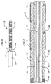
- Figure 1 is a side view of a catheter in accordance with a preferred embodiment of a present invention.
- Figure 2 is a section view of the distal end of the exemplary catheter illustrated in Figure 1.
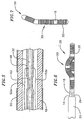
- Figure 3 is a top view of the distal region of the exemplary catheter illustrated in Figure 1.
- Figure 4 is a section view of a portion of the distal region of the exemplary catheter illustrated in Figure 1.
- Figure 5 is a section view of another portion of the distal region of the exemplary catheter illustrated in Figure 1.
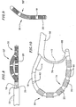
- Figure 6 is a top view of the distal region of the exemplary catheter illustrated in Figure 1 with a portion steered out of the loop plane.
- Figure 7 is an end view of the distal region of the exemplary catheter illustrated in Figure 1 with a portion steered out of the loop plane.
- Figure 8 is a top view of the distal region of another catheter in accordance with another preferred embodiment of a present invention with a portion steered out of the loop plane.
- Figure 9 is an end view of the exemplary catheter illustrated in Figure 8.
- Figure 10 is a side view of the distal region of a catheter in accordance with still another preferred embodiment of a present invention.
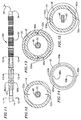
- Figure 11 is a side view of the distal region of a catheter in accordance with yet another preferred embodiment of a present invention with some of the electrodes shown in phantom lines for clarity.
- Figure 12 is a section view taken along line 12-12 in Figure 11.
- Figure 13 is a section view taken along line 13-13 in Figure 11.
- Figure 14 is an end view of the distal member in the exemplary catheter illustrated in Figure 11.
- Figure 15 is a section view taken along line 15-15 in Figure 11.
-
- The following is a detailed description of the best presently known modes of carrying out the inventions. This description is not to be taken in a limiting sense, but is made merely for the purpose of illustrating the general principles of the inventions.
- The detailed description of the preferred embodiments is organized as follows:
- I. Introduction
- II. Steerable Loop Structures
- III. Electrodes, Temperature Sensing and Power Control
-
- The section titles and overall organization of the present detailed description are for the purpose of convenience only and are not intended to limit the present inventions.
- The present inventions may be used within body lumens, chambers or cavities for diagnostic or therapeutic purposes in those instances where access to interior bodily regions is obtained through, for example, the vascular system or alimentary canal and without complex invasive surgical procedures. For example, the inventions herein have application in the diagnosis and treatment of arrhythmia conditions within the heart. The inventions herein also have application in the diagnosis or treatment of ailments of the gastrointestinal tract, prostrate, brain, gall bladder, uterus, and other regions of the body.
- With regard to the treatment of conditions within the heart, the present inventions are designed to produce intimate tissue contact with target substrates associated with various arrhythmias, namely atrial fibrillation, atrial flutter, and ventricular tachycardia. For example, embodiments of the present inventions, which may include diagnostic and/or soft tissue coagulation electrodes, can be used to map tissue and/or create lesions in tissue that cure arrhythmias.
- Although the present inventions are discussed primarily in the context of catheter-based probes, the inventions are also adaptable for use with probes other than catheter-based probes. For example, the structures disclosed herein may be used in conjunction with hand held surgical devices (or "surgical probes"). The distal end of a surgical probe may be placed directly in contact with the targeted tissue area by a physician during a surgical procedure, such as open heart surgery. Here, access may be obtained by way of a thoracotomy, median sternotomy, or thoracostomy. Exemplary surgical probes are disclosed in U.S. Patent No. 6,071,281.
- Surgical probe devices in accordance with the present inventions preferably include a handle, a relatively short shaft, and one of the distal assemblies described hereafter in the catheter context. Preferably, the length of the shaft is about 4 inches to about 18 inches (10.2 to 45.7 cm). This is relatively short in comparison to the portion of a catheter body that is inserted into the patient (typically from 23 to 55 inches (58.4 to 139.7 cm) in length) and the additional body portion that remains outside the patient. The shaft is also relatively stiff. In other words, the shaft is either rigid, malleable, or somewhat flexible. A rigid shaft cannot be bent. A malleable shaft is a shaft that can be readily bent by the physician to a desired shape, without springing back when released, so that it will remain in that shape during the surgical procedure. Thus, the stiffness of a malleable shaft must be low enough to allow the shaft to be bent, but high enough to resist bending when the forces associated with a surgical procedure are applied to the shaft. A somewhat flexible shaft will bend and spring back when released. However, the force required to bend the shaft must be substantial.
- As illustrated for example in Figures 1 and 2, a
catheter 10 in accordance with a preferred embodiment of a present invention includes a hollow,flexible catheter body 12 that is preferably formed from two tubular parts, or members. Theproximal member 14 is relatively long and is attached to ahandle 16, while thedistal member 18, which is relatively short, carries a plurality of spacedelectrodes 20 or other operative elements. Theproximal member 14 is typically formed from a biocompatible thermoplastic material, such as a Pebax® material (polyether block emide) and stainless steel braid composite, which has good torque transmission properties. In some implementations, an elongate guide coil (not shown) may also be provided within theproximal member 14. Thedistal member 18 is typically formed from a softer, more flexible biocompatible thermoplastic material such as unbraided Pebax® material, polyethylene, or polyurethane. The proximal and distal members, which are about 5 French to about 9 French (1.66 mm to 3 mm) in diameter, are preferably either bonded together with an overlapping thermal bond or adhesively bonded together end to end over a sleeve in what is referred to as a "butt bond." - The
catheter 10 is used in combination with asheath 22, which preferably has a greater inherent stiffness than the distal region of the catheter 12 (i.e. thedistal member 18, theelectrodes 20 and aspline 32 that is discussed below with reference to Figures 4 and 5). Thesheath 22 should also be lubricious to reduce friction during movement of thecatheter body 12. With respect to materials, thesheath 14 is preferably a Pebax® and stainless steel braid composite. Other materials, such as polytetrafluoroethylene (PTFE), can also be used. The wall thickness of thesheath 22 is preferably about 0.013 inch (3.3 mm), which will not add significantly to the overall thickness of thecatheter 10. Ahandle 24, which is preferably in the form of a hemostatic connector that can be used to fix the relative positions of thecatheter 12 andsheath 22, is mounted on the proximal end of the sheath. - In the exemplary embodiment illustrated in Figure 1, the distal end of the
sheath 22 is perpendicular to the longitudinal axis of the sheath. However, the distal end of thesheath 22 may also be cut at an angle and tapered in a transverse direction relative to the longitudinal axis of the sheath to effect the shape loop formed by the distal region of thecatheter 12. - A
pull wire 26 extends from the distal end of thecatheter 12 through thesheath 22 in the exemplary embodiment illustrated in Figure 1. The proximal end of thepull wire 26 includes an adjustable stop/handle 28. Thepull wire 26 is preferably a flexible, inert cable constructed from strands of metal wire material, such as Nickel Titanium (commercially available under the trade name Nitinol®) or 17-7 stainless steel, that is about 0.012 to 0.018 inch (0.30 to 0.46 mm) in diameter. Alternatively, thepull wire 26 may be formed from a flexible, inert stranded or molded plastic material. Thepull wire 26 is also .preferably round in cross-section, although other cross-sectional configurations can be used. - Holding the
handle 28 stationary, the physician deploys aloop structure 30 by advancing thecatheter body 12 through thesheath 22. Once theloop structure 30 has been formed, the physician can pull on thewire 26 to decrease the exposed length of the pull wire beyond the distal end of thesheath 22. Further adjustments to the loop may be made by advancing or retracting thecatheter body 12 within thesheath 22 or by putting tension on thepull wire 24. For example, a portion of theloop structure 30 my be bent out of the loop plane. This aspect of the invention is discussed in greater detail below with reference to Figures 5-9. In addition, theloop structure 30 can be rotated by rotating thecatheter body 12 with itshandle 16. - As illustrated in Figures 2 and 4, the
exemplary catheter body 12 also includes a flexible spline (or "core wire") 32. Theflexible spline 32 is preferably a wire having a diameter of approximately 0.023 inch (0.58 mm) that is positioned inside of and passes within the length of thecatheter body 12. Theflexible spline 32 is fixedly secured to thehandle 16 at the proximal end of thecatheter body 12 and to atip member 34 in the manner described below. Thetip member 34 is in turn secured to the distal end of thecatheter body 12 with adhesive. In the preferred embodiment, theflexible spline 32 is made from resilient, inert wire, such as Nitinol® material or 17-7 stainless steel. Resilient injection molded plastic can also be used. Theexemplary spline 32 is round in cross section, although other cross sectional configurations can be used. Theflexible spline 32 may, if desired, also have a preset curvature accomplished by thermally presetting the spline at 500°C for 8 minutes. The super-elastic properties of the material should, however, be maintained. - Referring more specifically to Figures 1, 3 and 4, the
flexible spline 32 includes a flattenedportion 36, which is preferably adjacent to (i.e. either just proximal to, just distal to, or aligned with) the proximal end of thedistal member 18, that allows this portion of the flexible spline to be bent with less force than would otherwise be required. The flattenedportion 36 also causes thedistal member 18 to bend, and theloop structure 30 to be formed, in a flat loop plane (note the side view in Figure 1 and the top view in Figure 3). In an embodiment where theflexible spline 32 has a diameter of approximately 0.023 inch (0.58 mm), the thickness of the flattenedportion 36 would be about 0.018 inch (0.46 mm) and the length would be about 1.75 inches (4.45 cm). - The
flexible spline 32 may also be used to anchor thepull wire 26. As illustrated for example in Figure 2, thedistal end 38 of theflexible spline 32 is fixedly engaged in an in-line manner to theend 40 of thepull wire 26 with a stainlesssteel crimp tube 42. The in-line connection of theflexible spline 32 and pullwire 26 allows for a reduction in the overall diameter of distal portion of thecatheter body 12. This provides a significant clinical advantage over devices having side by side pull wire connections which create a larger diameter device. Thepull wire 26 passes through a pull wire bore 44 in thecatheter tip member 24 and through abore 46 in the distal end of thecrimp tube 42. - The
tip member 34 is preferably formed from platinum-iridium (90/10) and is fixedly engaged with, for example, silver solder, adhesive or spot welding, to the distal end ofcrimp tube 42. Theflexible spline 32 is preferably electrically insulated with a thin walled polyester heat shrinktube 48 that extends beyond the proximal end of thecrimp tube 42. Other pull wire configurations, other methods of attaching the pull wire to the catheter body, and methods of reducing stress on the pull wire are disclosed in U.S. Patent No. 6,048,329. - The
exemplary catheter 10 present also includes a loop deflection system that allows the physician to steer aportion 50 of theloop structure 30 out of the loop plane in the manner illustrated in Figures 6 and 7. - As illustrated in Figures 1 and 5, the steering capability may, for example, be provided through the use of one or more steering wires. The
exemplary catheter 10 includes a pair ofsteering wires tube 48 and are secured to theflexible spline 32 with a crimp joint, solder, adhesive or other suitable instrumentalities.Steering wires exemplary handle 16, which includeshandle body 54 and asteering assembly 56 that consists of acam wheel 58 and alever 60. The proximal ends of each of thesteering wires cam wheel 58. Tension is applied tosteering wire 52a wire by urging thelever 60 proximally, while tension is applied to thesteering wire 52b by urging the lever distally.Portion 50 in Figures 6 and 7 has been steered out of the loop plane by moving the lever in the clockwise direction and can be steered in the opposite direction by moving the lever in the counter-clockwise direction. Additional information concerning this type of handle is disclosed in U.S. Patent No. 5,636,634. Other types of handles, such as piston and cylinder style handles, may also be employed. - The steering of
portion 50 may be facilitated by forming a second flattenedportion 62 in thespline 32 just proximally of the point at which thesteering wires portion 62, which is rotated 90 degrees relative to the flattenedportion 36, facilitates the steering ofportion 50 by giving the bend directionality and creating a live hinge. In an embodiment where theflexible spline 32 has a diameter of approximately 0.023 inch (0.58 mm), the thickness of the second flattenedportion 62 would be about 0.010 inch (0.25 mm) and the length would be about 0.50 inch (1.27 cm). - In an alternative embodiment, which is especially useful in situations that require a greater portion of the loop to be steered out of the loop plane, is illustrated in Figures 8 and 9. Steerable portion 50' is larger than the
steerable portion 50 illustrated in Figures 6 and 7 because the second flattened portion (not shown) in the embodiment illustrated in Figure 8 and 9 is longer than the second flattenedportion 62 illustrated in Figure 5. Here, a suitable length for the second flattenedportion 62 in an embodiment where theflexible spline 32 has a diameter of approximately 0.023 inch (0.58 mm) would be about 1.5 inches (3.81 cm). - The present inventions are also applicable to loop catheters in which the distal portion of catheter body is connected to the distal portion of the sheath. As illustrated for example in Figure 10, the
exemplary catheter 64 does not include a pull wire and instead is used in combination with asheath 66 which has adistal member 68 that is connected to the distal end of thecatheter 64. A slot is formed in the distal portion of thesheath 66 and the remnant 70 forms a flexible joint. A stiffeningelement 72 may also be provided. Theloop 74 is formed when thecatheter 64 is urged distally relative to thesheath 66, thereby causing the distal portion of the catheter to bulge outwardly in the manner illustrated in Figure 10. Although not shown in Figure 10,exemplary catheter 64 also includes the loop steering elements described above. - The loop steering elements described above may also be used in other loop catheters where the distal portion of catheter body is connected to the distal portion of the sheath. One example is a catheter wherein the distal end of the catheter body is connected to the distal end of a sheath by a short wire. This and other examples of such loop catheters are disclosed in U.S. Patent No. 6,071,274.
- In another alternative embodiment, and as illustrated for example in Figures 11-15, the
steering wires - The
exemplary catheter 84 illustrated in Figures 11-15 is in many respects identical to thecatheter 10 illustrated in Figures 1-7. Here, however, thesteering wires spline 32. Thesteering wires steering wire lumens steering wire lumens respective inlets 88a and 88b andoutlets steering wire lumens inlets 88a and 88b andoutlets portion 62. Although the exemplary distal member 18' could be formed by a multi-lumen extrusion process so if desired, the preferred process is a molding process. Here, core pins formed from flexible metal tubes could be used to form thesteering wire lumens - The distal ends of the
steering wires outlets electrodes 20 by, for example, welding or soldering. Alternatively, thesteering wires steering wires steering wire lumens - In an alternative implementation, the
steering wire lumens steering wire lumens inlets 88a and 88b would simply extend through the wall of the distal member 18' to the proximal ends of the channels. Guide coils, or other tubular members through which thesteering wires electrodes 20 would be placed over the channels and guide coils. - In each of the preferred embodiments, the operative elements are a plurality of spaced
electrodes 20. However, other operative elements, such as lumens for chemical ablation, laser arrays, ultrasonic transducers, microwave electrodes, and ohmically heated hot wires, and such devices may be substituted for the electrodes. - The.spaced
electrodes 20 are preferably in the form of wound, spiral coils. The coils are made of electrically conducting material, like copper alloy, platinum, or stainless steel, or compositions such as drawn-filled tubing (e.g. a copper core with a platinum jacket). The electrically conducting material of the coils can be further coated with platinum-iridium or gold to improve its conduction properties and biocompatibility. A preferred coil electrode is disclosed in U.S. Patent No. 5,797,905. Theelectrodes 20 are electrically coupled to individual wires (not shown) to conduct coagulating energy to them. The wires are passed in conventional fashion through a lumen extending through the associated catheter body into a PC board in the catheter handle, where they are electrically coupled to aconnector 76 that is received in a port on the handle. Aconnector 78 may be plugged into a source of RF coagulation energy and/or an electrophysiology recording system for mapping. - As an alternative, the electrodes may be in the form of solid rings of conductive material, like platinum, or can comprise a conductive material, like platinum-iridium or gold, coated upon the device using conventional coating techniques or an ion beam assisted deposition (IBAD) process. For better adherence, an undercoating of nickel or titanium can be applied. The electrodes can also be in the form of helical ribbons. The electrodes can also be formed with a conductive ink compound that is pad printed onto a nonconductive tubular body. A preferred conductive ink compound is a silver-based flexible adhesive conductive ink (polyurethane binder), however other metal-based adhesive conductive inks such as platinum-based, gold-based, copper-based, etc., may also be used to form electrodes. Such inks are more flexible than epoxy-based inks.
- The
flexible electrodes 20 are preferably about 4 mm to about 20 mm in length. In the preferred embodiment, the electrodes are 12.5 mm in length with 1 mm to 3 mm spacing, which will result in the creation of continuous lesion patterns in tissue when coagulation energy is applied simultaneously to adjacent electrodes. For rigid electrodes, the length of the each electrode can vary from about 2 mm to about 10 mm. Using multiple rigid electrodes longer than about 10 mm each adversely effects the overall flexibility of the device, while electrodes having lengths of less than about 2 mm do not consistently form the desired continuous lesion patterns. - The portion of the
electrodes 20 that are not intended to contact tissue (and be exposed to the blood pool) may be masked through a variety of techniques with a material that is preferably electrically and thermally insulating. This prevents the transmission of coagulation energy directly into the blood pool and directs the energy directly toward and into the tissue. For example, a layer of UV adhesive (or another adhesive) may be painted on preselected portions of the electrodes to insulate the portions of the electrodes not intended to contact tissue. Deposition techniques may also be implemented to position a conductive surface only on those portions of the assembly intended to contact tissue. Alternatively, a coating may be formed by dipping the electrodes in PTFE material. - The electrodes may be operated in a uni-polar mode, in which the soft tissue coagulation energy emitted by the electrodes is returned through an indifferent patch electrode (not shown) externally attached to the skin of the patient. Alternatively, the electrodes may be operated in a bi-polar mode, in which energy emitted by one or more electrodes is returned through other electrodes. The amount of power required to coagulate tissue ranges from 5 to 150 w.
- As illustrated for example in Figure 4, a plurality of
temperature sensors 80, such as thermocouples or thermistors, may be located on, under, abutting the longitudinal end edges of, or in between, theelectrodes 20. Preferably, thetemperature sensors 80 are located at the longitudinal edges of theelectrodes 20. In some embodiments, areference thermocouple 82 may also be provided. For temperature control purposes, signals from the temperature sensors are transmitted to the source of coagulation energy by way of wires (not shown) that are also connected to the aforementioned PC board in the catheter handle. Suitable temperature sensors and controllers which control power to electrodes based on a sensed temperature are disclosed in U.S. Patent Nos. 5,456,682, 5,582,609 and 5,755,715. - In those instances where the ultimate orientation of a catheter relative to tissue (i.e. which side faces the tissue) is unpredictable, such as when a catheter with a pull wire is used, the
temperature sensors 80 may be located on two sides of catheter, as illustrated in Figure 4. Alternatively, in those instances where the orientation is more predictable, such as when the catheter is secured to the distal end of the sheath, the temperature sensors may all be located on the same side of the catheter, as illustrated in Figure 10. Here, the temperature sensors will be preferably located within a linear channel (not shown) that is formed in thedistal member 18. The linear channel insures that the temperature sensors will directly face the tissue and be arranged in linear fashion. Such an arrangement results in more accurate temperature readings which, in turn, results in better temperature control. As such, the actual tissue temperature will more accurately correspond to the temperature set by the physician on the power control device, thereby providing the physician with better control of the lesion creation process and reducing the likelihood that embolic materials will be formed. Such a channel may be employed in conjunction with any of the electrode (or other operative element) supporting structures disclosed herein. - The
electrodes 20 andtemperature sensors 80 can include a porous material coating, which transmits coagulation energy through an electrified ionic medium. For example, as disclosed in U.S. Patent No. 5,991,650, electrodes and temperature sensors may be coated with regenerated cellulose, hydrogel or plastic having electrically conductive components. With respect to regenerated cellulose, the coating acts as a mechanical barrier between the surgical device components, such as electrodes, preventing ingress of blood cells, infectious agents, such as viruses and bacteria, and large biological molecules such as proteins, while providing electrical contact to the human body. The regenerated cellulose coating also acts as a biocompatible barrier between the device components and the human body, whereby the components can now be made from materials that are somewhat toxic (such as silver or copper). - Further preferred embodiments of the present invention are given in the following paragraphs:
- A first further preferred embodiment of the present invention is a probe for use with an outer member including a wall defining an interior bore, the probe comprising: an elongate body, defining a distal region, a distal end, a proximal region and an interior, adapted to be carried within the outer member interior bore; at least one operative element supported on the distal region of the elongate body; a control element defining a distal portion associated with the distal end of the elongate body and a proximal portion extending along the exterior of the elongate body toward the proximal region of the elongate body; and a steering element secured to the distal portion of the elongate body and extending within the interior of the elongate body to the proximal region of the elongate body.
- In a first aspect of the first further preferred embodiment of the present invention, said steering element comprises a pair of steering elements.
- In a second aspect of the first further preferred embodiment of the present invention, said elongate body comprises a catheter body.
- In a third aspect of the first further preferred embodiment of the present invention, at least the distal region of the elongate body includes a flexible spline. Said flexible spline may comprise a solid core wire. Said flexible spline may also define a substantially circular cross sectional shape over a substantial portion thereof and a substantially flat cross sectional shape over a relatively small portion thereof. Said steering element may be fixedly secured to the flexible spline.
- In a fourth aspect of the first further preferred embodiment of the present invention, said operative element comprises an electrode.
- In a fifth aspect of the first further preferred embodiment of the present invention, said proximal region of the elongate body is relatively long and stiff and the distal region of the elongate body is relatively short and flexible.
- In a sixth aspect of the first further preferred embodiment of the present invention, said control element comprises a pull wire.
- A second further preferred embodiment of the present invention is a probe for use with an outer member including a wall defining an interior bore and a distal end, the probe comprising: an elongate body, defining a distal region, a distal end, a proximal region and an interior, adapted to be carried within the outer member interior bore; at least one operative element supported on the distal region of the elongate body; a connector adapted to connect the distal end of the elongate body to the distal end of the outer member; and a steering element secured to the distal portion of the elongate body and extending within the interior of the elongate body to the proximal region of the elongate body.
- In a first aspect of the second further preferred embodiment of the present invention, said steering element comprises a pair of steering elements.
- In a second aspect of the second further preferred embodiment of the present invention, said elongate body comprises a catheter body.
- In a third aspect of the second further preferred embodiment of the present invention, at least the distal region of the elongate body includes a flexible spline. Said flexible spline may comprise a solid core wire. Said flexible spline may also define a substantially circular cross sectional shape over a substantial portion thereof and a substantially flat cross sectional shape over a relatively small portion thereof. Said steering element may be fixedly secured to the flexible spline.
- In a fourth aspect of the second further preferred embodiment of the present invention, said operative element comprises an electrode.
- In a fifth aspect of the second further preferred embodiment of the present invention, said proximal region of the elongate body is relatively long and stiff and the distal region of the elongate body is relatively short and flexible.
- In a sixth aspect of the second further preferred embodiment of the present invention, said connector is integral with the outer member.
- A third further preferred embodiment of the present invention is a probe, comprising: an elongate body defining a distal region and an interior; a loop structure defining an interior and associated with the distal region of the elongate body; at least one operative element supported on the loop structure; and a steering element secured to the interior of the loop structure and extending through the interior of the loop structure and the interior of the elongate body to the proximal region of the elongate body.
- In a first aspect of the third further preferred embodiment of the present invention, said steering element comprises a pair of steering elements.
- In a second aspect of the third further preferred embodiment of the present invention, said elongate body comprises a catheter body.
- In a third aspect of the third further preferred embodiment of the present invention, at least the distal region of the elongate body includes a flexible spline. Said flexible spline may comprise a solid core wire. Said flexible spline may also define a substantially circular cross sectional shape over a substantial portion thereof and a substantially flat cross sectional shape over a relatively small portion thereof. Said steering element may be fixedly secured to the flexible spline.
- In a fourth aspect of the third further preferred embodiment of the present invention, said operative element comprises an electrode.
- In a fifth aspect of the third further preferred embodiment of the present invention, said proximal region of the elongate body is relatively long and stiff and the distal region of the elongate body is relatively short and flexible.
- In a sixth aspect of the third further preferred embodiment of the present invention, said probe further comprises: a control element defining a distal portion associated with the loop structure and a proximal portion extending along the exterior of the elongate body toward the proximal region of the elongate body.
- A fourth further preferred embodiment of the present invention is a probe, comprising: an elongate body defining a distal region and a proximal region; at least one operative element supported on the distal region of the elongate body; and a steering element secured at a first side of the distal region of the elongate body and extending to a second side of the distal region opposite the first side of the distal region and from the second side of the distal region to the proximal region of the elongate body.
- In a first aspect of the fourth further preferred embodiment of the present invention, said distal portion of the elongate body defines a steering wire lumen extending from the first side to the second side.
- In a second aspect of the fourth further preferred embodiment of the present invention, said first side is offset from the second side by 180 degrees.
- In a third aspect of the fourth further preferred embodiment of the present invention, said steering wire is secured to the at least one operative element.
- Although the present inventions have been described in terms of the preferred embodiments above, numerous modifications and/or additions to the above-described preferred embodiments would be readily apparent to one skilled in the art. It is intended that the scope of the present inventions extend to all such modifications and/or additions and that the scope of the present inventions is limited solely by the claims set forth below.
Claims (11)
- A probe, comprising:characterized in that the steering element extends within the interior of the elongate body from the proximal region to the distal region.an elongate body defining a proximal region (14) and a distal region (18) and an interior;a loop structure (30, 74) defining an interior andassociated with the distal region of the elongate body;at least one operative element (20) supported on the loop structure; anda steering element (52a or 52b) extending through the interior of the loop structure and the interior of the elongate body to the proximal region of the elongate body and secured to the interior of the loop structure such that proximal movement of the steering element will deflect a portion of the loop structure relative to the remainder of the loop structure;
- The probe as claimed in claim 1, wherein the steering element comprises a pair of steering elements (52a and 52b).
- The probe as claimed in claim 1, wherein the elongate body comprises a catheter body (12, 64).
- The probe as claimed in claim 1, wherein at least the distal region (18) of the elongate body includes a flexible spline (32).
- The probe as claimed in claim 4, wherein the flexible spline (32) comprises a solid core wire.
- The probe as claimed in claim 4, wherein the flexible spline (32) defines a substantially circular cross sectional shape over a substantial portion thereof and a substantially flat cross sectional shape over a relatively small portion thereof (36).
- The probe as claimed in claim 4, wherein the steering element (52a or 52b) is fixedly secured to the flexible spline (32).
- The probe as claimed in claim 1, wherein the operative element (20) comprises an electrode.
- The probe as claimed in claim 1, wherein the proximal region (14) of the elongate body is relatively long and stiff and the distal region (18) of the elongate body is relatively short and flexible.
- The probe as claimed in any one of claims 1 through 9, further comprising:a connector (68) adapted to connect the distal end of the elongate body to the distal end of an outer member (66) in which the elongate body is carried such that the distal region of the elongate body defines the loop structure (74) when the elongate body is moved distally relative to the outer member.
- The probe as claimed in claim 10, wherein the connector (68) is integral with the outer member (66).
Applications Claiming Priority (3)
| Application Number | Priority Date | Filing Date | Title |
|---|---|---|---|
| US709087 | 2000-11-10 | ||
| US09/709,087 US6916306B1 (en) | 2000-11-10 | 2000-11-10 | Steerable loop structures for supporting diagnostic and therapeutic elements in contact with body tissue |
| EP01993425A EP1331893B1 (en) | 2000-11-10 | 2001-10-23 | Steerable loop structures for supporting diagnostic and therapeutic elements in contact with body tissue |
Related Parent Applications (1)
| Application Number | Title | Priority Date | Filing Date |
|---|---|---|---|
| EP01993425A Division EP1331893B1 (en) | 2000-11-10 | 2001-10-23 | Steerable loop structures for supporting diagnostic and therapeutic elements in contact with body tissue |
Publications (3)
| Publication Number | Publication Date |
|---|---|
| EP1510180A2 true EP1510180A2 (en) | 2005-03-02 |
| EP1510180A3 EP1510180A3 (en) | 2005-03-23 |
| EP1510180B1 EP1510180B1 (en) | 2007-04-11 |
Family
ID=24848428
Family Applications (2)
| Application Number | Title | Priority Date | Filing Date |
|---|---|---|---|
| EP01993425A Expired - Lifetime EP1331893B1 (en) | 2000-11-10 | 2001-10-23 | Steerable loop structures for supporting diagnostic and therapeutic elements in contact with body tissue |
| EP04028757A Expired - Lifetime EP1510180B1 (en) | 2000-11-10 | 2001-10-23 | Steerable loop structure |
Family Applications Before (1)
| Application Number | Title | Priority Date | Filing Date |
|---|---|---|---|
| EP01993425A Expired - Lifetime EP1331893B1 (en) | 2000-11-10 | 2001-10-23 | Steerable loop structures for supporting diagnostic and therapeutic elements in contact with body tissue |
Country Status (9)
| Country | Link |
|---|---|
| US (2) | US6916306B1 (en) |
| EP (2) | EP1331893B1 (en) |
| JP (1) | JP4167059B2 (en) |
| AT (2) | ATE359034T1 (en) |
| AU (1) | AU2002220651A1 (en) |
| CA (1) | CA2428314A1 (en) |
| DE (2) | DE60107711T2 (en) |
| ES (1) | ES2232678T3 (en) |
| WO (1) | WO2002038052A2 (en) |
Families Citing this family (75)
| Publication number | Priority date | Publication date | Assignee | Title |
|---|---|---|---|---|
| US6423055B1 (en) * | 1999-07-14 | 2002-07-23 | Cardiofocus, Inc. | Phototherapeutic wave guide apparatus |
| US8025661B2 (en) | 1994-09-09 | 2011-09-27 | Cardiofocus, Inc. | Coaxial catheter instruments for ablation with radiant energy |
| US6302880B1 (en) * | 1996-04-08 | 2001-10-16 | Cardima, Inc. | Linear ablation assembly |
| US9033961B2 (en) | 1999-07-14 | 2015-05-19 | Cardiofocus, Inc. | Cardiac ablation catheters for forming overlapping lesions |
| US7935108B2 (en) | 1999-07-14 | 2011-05-03 | Cardiofocus, Inc. | Deflectable sheath catheters |
| US8540704B2 (en) | 1999-07-14 | 2013-09-24 | Cardiofocus, Inc. | Guided cardiac ablation catheters |
| US8900219B2 (en) | 1999-07-14 | 2014-12-02 | Cardiofocus, Inc. | System and method for visualizing tissue during ablation procedures |
| US6916306B1 (en) * | 2000-11-10 | 2005-07-12 | Boston Scientific Scimed, Inc. | Steerable loop structures for supporting diagnostic and therapeutic elements in contact with body tissue |
| US6893436B2 (en) * | 2002-01-03 | 2005-05-17 | Afx, Inc. | Ablation instrument having a flexible distal portion |
| US20050256452A1 (en) * | 2002-11-15 | 2005-11-17 | Demarchi Thomas | Steerable vascular sheath |
| US20050165366A1 (en) | 2004-01-28 | 2005-07-28 | Brustad John R. | Medical tubing having variable characteristics and method of making same |
| US20050004515A1 (en) * | 2002-11-15 | 2005-01-06 | Hart Charles C. | Steerable kink resistant sheath |
| US20040199052A1 (en) | 2003-04-01 | 2004-10-07 | Scimed Life Systems, Inc. | Endoscopic imaging system |
| US7147635B2 (en) * | 2004-01-29 | 2006-12-12 | Ethicon, Inc. | Bipolar electrosurgical snare |
| US7582083B2 (en) | 2004-05-10 | 2009-09-01 | Boston Scientific Scimed, Inc. | Probe based low temperature lesion formation apparatus, systems and methods |
| US7291142B2 (en) | 2004-05-10 | 2007-11-06 | Boston Scientific Scimed, Inc. | Low temperature lesion formation apparatus, systems and methods |
| US7288088B2 (en) | 2004-05-10 | 2007-10-30 | Boston Scientific Scimed, Inc. | Clamp based low temperature lesion formation apparatus, systems and methods |
| US20060089637A1 (en) | 2004-10-14 | 2006-04-27 | Werneth Randell L | Ablation catheter |
| EP1807142A1 (en) * | 2004-11-01 | 2007-07-18 | Applied Medical Resources Corporation | Longitudinal sheath enforcement |
| US8617152B2 (en) | 2004-11-15 | 2013-12-31 | Medtronic Ablation Frontiers Llc | Ablation system with feedback |
| US7468062B2 (en) | 2004-11-24 | 2008-12-23 | Ablation Frontiers, Inc. | Atrial ablation catheter adapted for treatment of septal wall arrhythmogenic foci and method of use |
| US7429261B2 (en) | 2004-11-24 | 2008-09-30 | Ablation Frontiers, Inc. | Atrial ablation catheter and method of use |
| WO2006091597A1 (en) * | 2005-02-22 | 2006-08-31 | Cardiofocus, Inc. | Deflectable sheath catheters |
| US8070685B2 (en) * | 2005-04-15 | 2011-12-06 | Imacor Inc. | Connectorized probe for transesophageal echocardiography |
| US7988735B2 (en) * | 2005-06-15 | 2011-08-02 | Matthew Yurek | Mechanical apparatus and method for delivering materials into the inter-vertebral body space for nucleus replacement |
| EP1895927A4 (en) | 2005-06-20 | 2011-03-09 | Medtronic Ablation Frontiers | Ablation catheter |
| US8834461B2 (en) | 2005-07-11 | 2014-09-16 | Medtronic Ablation Frontiers Llc | Low power tissue ablation system |
| US8657814B2 (en) | 2005-08-22 | 2014-02-25 | Medtronic Ablation Frontiers Llc | User interface for tissue ablation system |
| WO2007055521A1 (en) * | 2005-11-09 | 2007-05-18 | Korea University Industrial & Academic Collaboration Foundation | Radio frequency ablation electrode for selected tissue removal |
| FR2896698B1 (en) * | 2006-02-02 | 2008-09-19 | Vygon Sa | NEUROSTIMULATION CATHETER AND ITS BASE |
| WO2007134341A2 (en) * | 2006-05-17 | 2007-11-22 | Applied Medical Resources Corporation | Steerable sheath actuator |
| WO2007137184A2 (en) * | 2006-05-18 | 2007-11-29 | Applied Medical Resources Corporation | Method of making medical tubing having variable characteristics using thermal winding |
| US8992470B2 (en) * | 2006-05-19 | 2015-03-31 | Boston Scientific Scimed, Inc. | Control mechanism for steerable medical device |
| EP2136714A4 (en) * | 2007-02-06 | 2013-04-03 | Microcube Llc | A delivery system for delivering a medical device to a location within a patient's body |
| US10932848B2 (en) | 2007-02-06 | 2021-03-02 | Microcube, Llc | Delivery system for delivering a medical device to a location within a patient's body |
| US11660190B2 (en) | 2007-03-13 | 2023-05-30 | Edwards Lifesciences Corporation | Tissue anchors, systems and methods, and devices |
| US8641704B2 (en) | 2007-05-11 | 2014-02-04 | Medtronic Ablation Frontiers Llc | Ablation therapy system and method for treating continuous atrial fibrillation |
| US20090131867A1 (en) | 2007-11-16 | 2009-05-21 | Liu Y King | Steerable vertebroplasty system with cavity creation element |
| US20090131886A1 (en) | 2007-11-16 | 2009-05-21 | Liu Y King | Steerable vertebroplasty system |
| US9510885B2 (en) | 2007-11-16 | 2016-12-06 | Osseon Llc | Steerable and curvable cavity creation system |
| US8636270B2 (en) * | 2007-12-19 | 2014-01-28 | Boston Scientific Scimed, Inc. | Structure for use as part of a medical device |
| EP2249691B1 (en) * | 2008-01-24 | 2013-07-03 | Boston Scientific Scimed, Inc. | Structure for use as part of a medical device |
| WO2009120622A1 (en) * | 2008-03-24 | 2009-10-01 | Boston Scientific Scimed, Inc. | Flexible endoscope with core member |
| JP4545210B2 (en) * | 2008-09-11 | 2010-09-15 | 日本ライフライン株式会社 | Defibrillation catheter |
| US10695126B2 (en) | 2008-10-06 | 2020-06-30 | Santa Anna Tech Llc | Catheter with a double balloon structure to generate and apply a heated ablative zone to tissue |
| JP4545216B1 (en) * | 2009-03-23 | 2010-09-15 | 日本ライフライン株式会社 | Intracardiac defibrillation catheter system |
| US20100298832A1 (en) | 2009-05-20 | 2010-11-25 | Osseon Therapeutics, Inc. | Steerable curvable vertebroplasty drill |
| US20110046657A1 (en) * | 2009-08-20 | 2011-02-24 | Boston Scientific Scimed, Inc. | Embolic Coil Introducer Catheter Locking Mechanisms |
| US8696653B2 (en) | 2009-10-02 | 2014-04-15 | Cardiofocus, Inc. | Cardiac ablation system with pulsed aiming light |
| WO2011044248A2 (en) | 2009-10-06 | 2011-04-14 | Cardiofocus, Inc. | Cardiac ablation image analysis system and process |
| CN102958456B (en) | 2010-04-29 | 2015-12-16 | Dfine有限公司 | Be used for the treatment of the system of vertebral fracture |
| CA2806278C (en) | 2010-07-28 | 2020-08-04 | Medrobotics Corporation | Surgical positioning and support system |
| WO2012054829A2 (en) | 2010-10-22 | 2012-04-26 | Medrobotics Corporation | Highly articulated robotic probes and methods of production and use of such probes |
| EP2637551B1 (en) | 2010-11-11 | 2019-10-02 | Medrobotics Corporation | Introduction devices for highly articulated robotic probes |
| EP3321042A1 (en) | 2011-09-13 | 2018-05-16 | Medrobotics Corporation | Highly articulated probes with anti-twist link arrangement |
| DE102011085721A1 (en) * | 2011-11-03 | 2013-05-08 | Günter Farin | HF surgical resection instrument with a resection loop for removal of pathological tissue |
| KR20140104502A (en) * | 2011-12-21 | 2014-08-28 | 메드로보틱스 코포레이션 | Stabilizing apparatus for highly articulated probes with link arrangement, methods of formation thereof, and methods of use thereof |
| CN105283214B (en) | 2013-03-15 | 2018-10-16 | 北京泰德制药股份有限公司 | Translate conduit, system and its application method |
| US20150045696A1 (en) * | 2013-08-09 | 2015-02-12 | Oscor Inc. | Steerable dilator |
| US9907570B2 (en) | 2013-08-23 | 2018-03-06 | Oscor Inc. | Steerable medical devices |
| US10070857B2 (en) | 2013-08-31 | 2018-09-11 | Mitralign, Inc. | Devices and methods for locating and implanting tissue anchors at mitral valve commissure |
| EP2881057A1 (en) * | 2013-12-05 | 2015-06-10 | Region Nordjylland | Apparatus for creating linear lesions in body tissue within a body vessel |
| EP3137007A4 (en) | 2014-04-28 | 2017-09-27 | Cardiofocus, Inc. | System and method for visualizing tissue with an icg dye composition during ablation procedures |
| WO2016089900A2 (en) | 2014-12-03 | 2016-06-09 | Cardiofocus, Inc. | System and method for visual confirmation of pulmonary vein isolation during ablation procedures |
| WO2017120330A1 (en) | 2016-01-05 | 2017-07-13 | Cardiofocus, Inc. | Ablation system with automated sweeping ablation energy element |
| US11331140B2 (en) | 2016-05-19 | 2022-05-17 | Aqua Heart, Inc. | Heated vapor ablation systems and methods for treating cardiac conditions |
| WO2018081279A1 (en) | 2016-10-27 | 2018-05-03 | Dfine, Inc. | Articulating osteotome with cement delivery channel |
| US11116570B2 (en) | 2016-11-28 | 2021-09-14 | Dfine, Inc. | Tumor ablation devices and related methods |
| EP3551100B1 (en) | 2016-12-09 | 2021-11-10 | Dfine, Inc. | Medical devices for treating hard tissues |
| WO2018129180A1 (en) | 2017-01-06 | 2018-07-12 | Dfine, Inc. | Osteotome with a distal portion for simultaneous advancement and articulation |
| USD851245S1 (en) | 2017-04-14 | 2019-06-11 | Cardiofocus, Inc. | Compliant balloon |
| US10695073B2 (en) | 2017-08-22 | 2020-06-30 | Arthrex, Inc. | Control system for retrograde drill medical device |
| JP7384798B2 (en) | 2018-01-15 | 2023-11-21 | カーディオフォーカス,インコーポレーテッド | Ablation system using automated ablation energy elements |
| WO2020097339A1 (en) | 2018-11-08 | 2020-05-14 | Dfine, Inc. | Tumor ablation device and related systems and methods |
| JP2021171563A (en) * | 2020-04-30 | 2021-11-01 | ジェイソル・メディカル株式会社 | Catheter for measuring cardiac potential |
Citations (8)
| Publication number | Priority date | Publication date | Assignee | Title |
|---|---|---|---|---|
| US5456682A (en) | 1991-11-08 | 1995-10-10 | Ep Technologies, Inc. | Electrode and associated systems using thermally insulated temperature sensing elements |
| US5582609A (en) | 1993-10-14 | 1996-12-10 | Ep Technologies, Inc. | Systems and methods for forming large lesions in body tissue using curvilinear electrode elements |
| US5636634A (en) | 1993-03-16 | 1997-06-10 | Ep Technologies, Inc. | Systems using guide sheaths for introducing, deploying, and stabilizing cardiac mapping and ablation probes |
| US5797905A (en) | 1994-08-08 | 1998-08-25 | E. P. Technologies Inc. | Flexible tissue ablation elements for making long lesions |
| US6048329A (en) | 1996-12-19 | 2000-04-11 | Ep Technologies, Inc. | Catheter distal assembly with pull wires |
| US6071279A (en) | 1996-12-19 | 2000-06-06 | Ep Technologies, Inc. | Branched structures for supporting multiple electrode elements |
| US6071274A (en) | 1996-12-19 | 2000-06-06 | Ep Technologies, Inc. | Loop structures for supporting multiple electrode elements |
| US6071281A (en) | 1998-05-05 | 2000-06-06 | Ep Technologies, Inc. | Surgical method and apparatus for positioning a diagnostic or therapeutic element within the body and remote power control unit for use with same |
Family Cites Families (68)
| Publication number | Priority date | Publication date | Assignee | Title |
|---|---|---|---|---|
| US1207479A (en) | 1915-03-05 | 1916-12-05 | Holger Bisgaard | Self-retaining gatheter. |
| US4033331A (en) | 1975-07-17 | 1977-07-05 | Guss Stephen B | Cardiac catheter and method of using same |
| US4245624A (en) | 1977-01-20 | 1981-01-20 | Olympus Optical Co., Ltd. | Endoscope with flexible tip control |
| US4181131A (en) | 1977-02-28 | 1980-01-01 | Olympus Optical Co., Ltd. | High frequency electrosurgical instrument for cutting human body cavity structures |
| GB8503547D0 (en) | 1985-02-12 | 1985-03-13 | British Petroleum Co Plc | Nozzle |
| NL8600338A (en) | 1986-02-11 | 1987-09-01 | Louis Johannes Karel Jozef Rey | CATHETER PROVIDED WITH POSITIONERS. |
| US4753223A (en) | 1986-11-07 | 1988-06-28 | Bremer Paul W | System for controlling shape and direction of a catheter, cannula, electrode, endoscope or similar article |
| DE3920707A1 (en) | 1989-06-24 | 1991-01-10 | Foerster Ernst | catheter with flexible end piece - which can be deflected by control wire in guide on side of catheter body |
| GB8924946D0 (en) | 1989-11-04 | 1989-12-28 | Shiu Man F | Support system for catheter |
| US5273535A (en) | 1991-11-08 | 1993-12-28 | Ep Technologies, Inc. | Catheter with electrode tip having asymmetric left and right curve configurations |
| US5820591A (en) | 1990-02-02 | 1998-10-13 | E. P. Technologies, Inc. | Assemblies for creating compound curves in distal catheter regions |
| US6413234B1 (en) * | 1990-02-02 | 2002-07-02 | Ep Technologies, Inc. | Assemblies for creating compound curves in distal catheter regions |
| US5041085A (en) | 1990-02-26 | 1991-08-20 | Cook Incorporated | Percutaneous lockable sleeve catheter |
| US5156151A (en) | 1991-02-15 | 1992-10-20 | Cardiac Pathways Corporation | Endocardial mapping and ablation system and catheter probe |
| US5584803A (en) | 1991-07-16 | 1996-12-17 | Heartport, Inc. | System for cardiac procedures |
| JPH06509963A (en) | 1991-08-28 | 1994-11-10 | メドトロニック インコーポレーテッド | Operable stylet and operation handle assembly |
| US5263493A (en) | 1992-02-24 | 1993-11-23 | Boaz Avitall | Deflectable loop electrode array mapping and ablation catheter for cardiac chambers |
| US5318525A (en) | 1992-04-10 | 1994-06-07 | Medtronic Cardiorhythm | Steerable electrode catheter |
| WO1993020886A1 (en) | 1992-04-13 | 1993-10-28 | Ep Technologies, Inc. | Articulated systems for cardiac ablation |
| US5324284A (en) | 1992-06-05 | 1994-06-28 | Cardiac Pathways, Inc. | Endocardial mapping and ablation system utilizing a separately controlled ablation catheter and method |
| US5782239A (en) | 1992-06-30 | 1998-07-21 | Cordis Webster, Inc. | Unique electrode configurations for cardiovascular electrode catheter with built-in deflection method and central puller wire |
| CA2109980A1 (en) | 1992-12-01 | 1994-06-02 | Mir A. Imran | Steerable catheter with adjustable bend location and/or radius and method |
| IT1266217B1 (en) | 1993-01-18 | 1996-12-27 | Xtrode Srl | ELECTROCATHETER FOR MAPPING AND INTERVENTION ON HEART CAVITIES. |
| DE69409018T2 (en) | 1993-01-28 | 1998-07-23 | Cook Inc | Holding device for catheters |
| US6161543A (en) | 1993-02-22 | 2000-12-19 | Epicor, Inc. | Methods of epicardial ablation for creating a lesion around the pulmonary veins |
| US5306245A (en) | 1993-02-23 | 1994-04-26 | Advanced Surgical Inc. | Articulating device |
| US5571088A (en) | 1993-07-01 | 1996-11-05 | Boston Scientific Corporation | Ablation catheters |
| US5562619A (en) | 1993-08-19 | 1996-10-08 | Boston Scientific Corporation | Deflectable catheter |
| US5415656A (en) | 1993-09-28 | 1995-05-16 | American Medical Systems, Inc. | Electrosurgical apparatus |
| US5437665A (en) | 1993-10-12 | 1995-08-01 | Munro; Malcolm G. | Electrosurgical loop electrode instrument for laparoscopic surgery |
| US5545193A (en) | 1993-10-15 | 1996-08-13 | Ep Technologies, Inc. | Helically wound radio-frequency emitting electrodes for creating lesions in body tissue |
| WO1995010322A1 (en) | 1993-10-15 | 1995-04-20 | Ep Technologies, Inc. | Creating complex lesion patterns in body tissue |
| WO1995010225A1 (en) | 1993-10-15 | 1995-04-20 | Ep Technologies, Inc. | Multiple electrode element for mapping and ablating |
| US5730127A (en) | 1993-12-03 | 1998-03-24 | Avitall; Boaz | Mapping and ablation catheter system |
| US5487385A (en) | 1993-12-03 | 1996-01-30 | Avitall; Boaz | Atrial mapping and ablation catheter system |
| US5882333A (en) | 1994-05-13 | 1999-03-16 | Cardima, Inc. | Catheter with deflectable distal section |
| DE4425195C1 (en) | 1994-07-16 | 1995-11-16 | Osypka Peter | Heart catheter with multiple electrode device |
| US5836947A (en) | 1994-10-07 | 1998-11-17 | Ep Technologies, Inc. | Flexible structures having movable splines for supporting electrode elements |
| US5885278A (en) | 1994-10-07 | 1999-03-23 | E.P. Technologies, Inc. | Structures for deploying movable electrode elements |
| US6464700B1 (en) | 1994-10-07 | 2002-10-15 | Scimed Life Systems, Inc. | Loop structures for positioning a diagnostic or therapeutic element on the epicardium or other organ surface |
| US5709224A (en) | 1995-06-07 | 1998-01-20 | Radiotherapeutics Corporation | Method and device for permanent vessel occlusion |
| US5702438A (en) | 1995-06-08 | 1997-12-30 | Avitall; Boaz | Expandable recording and ablation catheter system |
| US5800484A (en) | 1995-08-15 | 1998-09-01 | Rita Medical Systems, Inc. | Multiple antenna ablation apparatus with expanded electrodes |
| US5571038A (en) * | 1995-08-15 | 1996-11-05 | Halling; Richard | Model airplane flight simulator |
| US6007531A (en) * | 1995-11-21 | 1999-12-28 | Catheter Imaging Systems, Inc. | Steerable catheter having disposable module and sterilizable handle and method of connecting same |
| US5800482A (en) | 1996-03-06 | 1998-09-01 | Cardiac Pathways Corporation | Apparatus and method for linear lesion ablation |
| US5895417A (en) | 1996-03-06 | 1999-04-20 | Cardiac Pathways Corporation | Deflectable loop design for a linear lesion ablation apparatus |
| US5863291A (en) | 1996-04-08 | 1999-01-26 | Cardima, Inc. | Linear ablation assembly |
| US6311692B1 (en) | 1996-10-22 | 2001-11-06 | Epicor, Inc. | Apparatus and method for diagnosis and therapy of electrophysiological disease |
| US6237605B1 (en) | 1996-10-22 | 2001-05-29 | Epicor, Inc. | Methods of epicardial ablation |
| US6203525B1 (en) | 1996-12-19 | 2001-03-20 | Ep Technologies, Inc. | Catheterdistal assembly with pull wires |
| US5910129A (en) | 1996-12-19 | 1999-06-08 | Ep Technologies, Inc. | Catheter distal assembly with pull wires |
| US6332880B1 (en) * | 1996-12-19 | 2001-12-25 | Ep Technologies, Inc. | Loop structures for supporting multiple electrode elements |
| US6146355A (en) * | 1996-12-30 | 2000-11-14 | Myelotec, Inc. | Steerable catheter |
| US5879295A (en) | 1997-04-02 | 1999-03-09 | Medtronic, Inc. | Enhanced contact steerable bowing electrode catheter assembly |
| US5971983A (en) | 1997-05-09 | 1999-10-26 | The Regents Of The University Of California | Tissue ablation device and method of use |
| US6012457A (en) | 1997-07-08 | 2000-01-11 | The Regents Of The University Of California | Device and method for forming a circumferential conduction block in a pulmonary vein |
| US6490474B1 (en) | 1997-08-01 | 2002-12-03 | Cardiac Pathways Corporation | System and method for electrode localization using ultrasound |
| US6120500A (en) | 1997-11-12 | 2000-09-19 | Daig Corporation | Rail catheter ablation and mapping system |
| US6064902A (en) | 1998-04-16 | 2000-05-16 | C.R. Bard, Inc. | Pulmonary vein ablation catheter |
| US6016811A (en) | 1998-09-01 | 2000-01-25 | Fidus Medical Technology Corporation | Method of using a microwave ablation catheter with a loop configuration |
| US6190382B1 (en) | 1998-12-14 | 2001-02-20 | Medwaves, Inc. | Radio-frequency based catheter system for ablation of body tissues |
| US6217528B1 (en) * | 1999-02-11 | 2001-04-17 | Scimed Life Systems, Inc. | Loop structure having improved tissue contact capability |
| US6613046B1 (en) | 1999-11-22 | 2003-09-02 | Scimed Life Systems, Inc. | Loop structures for supporting diagnostic and therapeutic elements in contact with body tissue |
| US6529756B1 (en) | 1999-11-22 | 2003-03-04 | Scimed Life Systems, Inc. | Apparatus for mapping and coagulating soft tissue in or around body orifices |
| US6645199B1 (en) | 1999-11-22 | 2003-11-11 | Scimed Life Systems, Inc. | Loop structures for supporting diagnostic and therapeutic elements contact with body tissue and expandable push devices for use with same |
| US6542781B1 (en) | 1999-11-22 | 2003-04-01 | Scimed Life Systems, Inc. | Loop structures for supporting diagnostic and therapeutic elements in contact with body tissue |
| US6916306B1 (en) * | 2000-11-10 | 2005-07-12 | Boston Scientific Scimed, Inc. | Steerable loop structures for supporting diagnostic and therapeutic elements in contact with body tissue |
-
2000
- 2000-11-10 US US09/709,087 patent/US6916306B1/en not_active Expired - Lifetime
-
2001
- 2001-10-23 AT AT04028757T patent/ATE359034T1/en not_active IP Right Cessation
- 2001-10-23 WO PCT/EP2001/012243 patent/WO2002038052A2/en active IP Right Grant
- 2001-10-23 CA CA002428314A patent/CA2428314A1/en not_active Abandoned
- 2001-10-23 AU AU2002220651A patent/AU2002220651A1/en not_active Abandoned
- 2001-10-23 EP EP01993425A patent/EP1331893B1/en not_active Expired - Lifetime
- 2001-10-23 DE DE60107711T patent/DE60107711T2/en not_active Expired - Fee Related
- 2001-10-23 ES ES01993425T patent/ES2232678T3/en not_active Expired - Lifetime
- 2001-10-23 JP JP2002540642A patent/JP4167059B2/en not_active Expired - Fee Related
- 2001-10-23 EP EP04028757A patent/EP1510180B1/en not_active Expired - Lifetime
- 2001-10-23 DE DE60127876T patent/DE60127876T2/en not_active Expired - Lifetime
- 2001-10-23 AT AT01993425T patent/ATE284172T1/en not_active IP Right Cessation
-
2005
- 2005-05-17 US US11/130,857 patent/US7182764B2/en not_active Expired - Lifetime
Patent Citations (8)
| Publication number | Priority date | Publication date | Assignee | Title |
|---|---|---|---|---|
| US5456682A (en) | 1991-11-08 | 1995-10-10 | Ep Technologies, Inc. | Electrode and associated systems using thermally insulated temperature sensing elements |
| US5636634A (en) | 1993-03-16 | 1997-06-10 | Ep Technologies, Inc. | Systems using guide sheaths for introducing, deploying, and stabilizing cardiac mapping and ablation probes |
| US5582609A (en) | 1993-10-14 | 1996-12-10 | Ep Technologies, Inc. | Systems and methods for forming large lesions in body tissue using curvilinear electrode elements |
| US5797905A (en) | 1994-08-08 | 1998-08-25 | E. P. Technologies Inc. | Flexible tissue ablation elements for making long lesions |
| US6048329A (en) | 1996-12-19 | 2000-04-11 | Ep Technologies, Inc. | Catheter distal assembly with pull wires |
| US6071279A (en) | 1996-12-19 | 2000-06-06 | Ep Technologies, Inc. | Branched structures for supporting multiple electrode elements |
| US6071274A (en) | 1996-12-19 | 2000-06-06 | Ep Technologies, Inc. | Loop structures for supporting multiple electrode elements |
| US6071281A (en) | 1998-05-05 | 2000-06-06 | Ep Technologies, Inc. | Surgical method and apparatus for positioning a diagnostic or therapeutic element within the body and remote power control unit for use with same |
Also Published As
| Publication number | Publication date |
|---|---|
| AU2002220651A1 (en) | 2002-05-21 |
| EP1510180B1 (en) | 2007-04-11 |
| DE60127876D1 (en) | 2007-05-24 |
| WO2002038052A3 (en) | 2002-10-31 |
| EP1331893B1 (en) | 2004-12-08 |
| JP4167059B2 (en) | 2008-10-15 |
| US7182764B2 (en) | 2007-02-27 |
| EP1331893A2 (en) | 2003-08-06 |
| ES2232678T3 (en) | 2005-06-01 |
| US20050215992A1 (en) | 2005-09-29 |
| ATE284172T1 (en) | 2004-12-15 |
| DE60127876T2 (en) | 2007-12-20 |
| DE60107711D1 (en) | 2005-01-13 |
| WO2002038052A2 (en) | 2002-05-16 |
| US6916306B1 (en) | 2005-07-12 |
| JP2004512894A (en) | 2004-04-30 |
| ATE359034T1 (en) | 2007-05-15 |
| CA2428314A1 (en) | 2002-05-16 |
| EP1510180A3 (en) | 2005-03-23 |
| DE60107711T2 (en) | 2005-12-15 |
Similar Documents
| Publication | Publication Date | Title |
|---|---|---|
| EP1510180B1 (en) | Steerable loop structure | |
| US6217528B1 (en) | Loop structure having improved tissue contact capability | |
| CA2391488C (en) | Loop structures for supporting diagnostic and therapeutic elements in contact with body tissue | |
| US6613046B1 (en) | Loop structures for supporting diagnostic and therapeutic elements in contact with body tissue | |
| US6542781B1 (en) | Loop structures for supporting diagnostic and therapeutic elements in contact with body tissue | |
| US8798706B2 (en) | Loop structures for supporting diagnostic and/or therapeutic elements in contact with tissue | |
| US6711444B2 (en) | Methods of deploying helical diagnostic and therapeutic element supporting structures within the body | |
| US6745080B2 (en) | Helical and pre-oriented loop structures for supporting diagnostic and therapeutic elements in contact with body tissue | |
| US6692491B1 (en) | Surgical methods and apparatus for positioning a diagnostic or therapeutic element around one or more pulmonary veins or other body structures | |
| US9186481B2 (en) | Preshaped ablation catheter for ablating pulmonary vein ostia within the heart | |
| US6464699B1 (en) | Method and apparatus for positioning a diagnostic or therapeutic element on body tissue and mask element for use with same | |
| US6645200B1 (en) | Method and apparatus for positioning a diagnostic or therapeutic element within the body and tip electrode for use with same | |
| US8702696B2 (en) | Variable size apparatus for supporting diagnostic and/or therapeutic elements in contact with tissue | |
| WO2001072234A1 (en) | Loop structure for positioning a diagnostic or therapeutic element on the epicardium or other organ surface |
Legal Events
| Date | Code | Title | Description |
|---|---|---|---|
| PUAI | Public reference made under article 153(3) epc to a published international application that has entered the european phase |
Free format text: ORIGINAL CODE: 0009012 |
|
| PUAL | Search report despatched |
Free format text: ORIGINAL CODE: 0009013 |
|
| AC | Divisional application: reference to earlier application |
Ref document number: 1331893 Country of ref document: EP Kind code of ref document: P |
|
| AK | Designated contracting states |
Kind code of ref document: A2 Designated state(s): AT BE CH CY DE DK ES FI FR GB GR IE IT LI LU MC NL PT SE TR |
|
| AK | Designated contracting states |
Kind code of ref document: A3 Designated state(s): AT BE CH CY DE DK ES FI FR GB GR IE IT LI LU MC NL PT SE TR |
|
| 17P | Request for examination filed |
Effective date: 20050923 |
|
| AKX | Designation fees paid |
Designated state(s): AT BE CH CY DE DK ES FI FR GB GR IE IT LI LU MC NL PT SE TR |
|
| GRAP | Despatch of communication of intention to grant a patent |
Free format text: ORIGINAL CODE: EPIDOSNIGR1 |
|
| GRAS | Grant fee paid |
Free format text: ORIGINAL CODE: EPIDOSNIGR3 |
|
| GRAA | (expected) grant |
Free format text: ORIGINAL CODE: 0009210 |
|
| RAP1 | Party data changed (applicant data changed or rights of an application transferred) |
Owner name: BOSTON SCIENTIFIC LIMITED |
|
| AC | Divisional application: reference to earlier application |
Ref document number: 1331893 Country of ref document: EP Kind code of ref document: P |
|
| AK | Designated contracting states |
Kind code of ref document: B1 Designated state(s): AT BE CH CY DE DK ES FI FR GB GR IE IT LI LU MC NL PT SE TR |
|
| PG25 | Lapsed in a contracting state [announced via postgrant information from national office to epo] |
Ref country code: FI Free format text: LAPSE BECAUSE OF FAILURE TO SUBMIT A TRANSLATION OF THE DESCRIPTION OR TO PAY THE FEE WITHIN THE PRESCRIBED TIME-LIMIT Effective date: 20070411 Ref country code: LI Free format text: LAPSE BECAUSE OF FAILURE TO SUBMIT A TRANSLATION OF THE DESCRIPTION OR TO PAY THE FEE WITHIN THE PRESCRIBED TIME-LIMIT Effective date: 20070411 Ref country code: CH Free format text: LAPSE BECAUSE OF FAILURE TO SUBMIT A TRANSLATION OF THE DESCRIPTION OR TO PAY THE FEE WITHIN THE PRESCRIBED TIME-LIMIT Effective date: 20070411 |
|
| REG | Reference to a national code |
Ref country code: GB Ref legal event code: FG4D |
|
| REG | Reference to a national code |
Ref country code: CH Ref legal event code: EP |
|
| REG | Reference to a national code |
Ref country code: IE Ref legal event code: FG4D |
|
| REF | Corresponds to: |
Ref document number: 60127876 Country of ref document: DE Date of ref document: 20070524 Kind code of ref document: P |
|
| PG25 | Lapsed in a contracting state [announced via postgrant information from national office to epo] |
Ref country code: SE Free format text: LAPSE BECAUSE OF FAILURE TO SUBMIT A TRANSLATION OF THE DESCRIPTION OR TO PAY THE FEE WITHIN THE PRESCRIBED TIME-LIMIT Effective date: 20070711 |
|
| PG25 | Lapsed in a contracting state [announced via postgrant information from national office to epo] |
Ref country code: ES Free format text: LAPSE BECAUSE OF FAILURE TO SUBMIT A TRANSLATION OF THE DESCRIPTION OR TO PAY THE FEE WITHIN THE PRESCRIBED TIME-LIMIT Effective date: 20070722 |
|
| PG25 | Lapsed in a contracting state [announced via postgrant information from national office to epo] |
Ref country code: PT Free format text: LAPSE BECAUSE OF FAILURE TO SUBMIT A TRANSLATION OF THE DESCRIPTION OR TO PAY THE FEE WITHIN THE PRESCRIBED TIME-LIMIT Effective date: 20070911 |
|
| NLR4 | Nl: receipt of corrected translation in the netherlands language at the initiative of the proprietor of the patent | ||
| ET | Fr: translation filed | ||
| REG | Reference to a national code |
Ref country code: CH Ref legal event code: PL |
|
| PG25 | Lapsed in a contracting state [announced via postgrant information from national office to epo] |
Ref country code: AT Free format text: LAPSE BECAUSE OF FAILURE TO SUBMIT A TRANSLATION OF THE DESCRIPTION OR TO PAY THE FEE WITHIN THE PRESCRIBED TIME-LIMIT Effective date: 20070411 |
|
| PG25 | Lapsed in a contracting state [announced via postgrant information from national office to epo] |
Ref country code: BE Free format text: LAPSE BECAUSE OF FAILURE TO SUBMIT A TRANSLATION OF THE DESCRIPTION OR TO PAY THE FEE WITHIN THE PRESCRIBED TIME-LIMIT Effective date: 20070411 |
|
| PG25 | Lapsed in a contracting state [announced via postgrant information from national office to epo] |
Ref country code: DK Free format text: LAPSE BECAUSE OF FAILURE TO SUBMIT A TRANSLATION OF THE DESCRIPTION OR TO PAY THE FEE WITHIN THE PRESCRIBED TIME-LIMIT Effective date: 20070411 |
|
| PLBE | No opposition filed within time limit |
Free format text: ORIGINAL CODE: 0009261 |
|
| STAA | Information on the status of an ep patent application or granted ep patent |
Free format text: STATUS: NO OPPOSITION FILED WITHIN TIME LIMIT |
|
| 26N | No opposition filed |
Effective date: 20080114 |
|
| PG25 | Lapsed in a contracting state [announced via postgrant information from national office to epo] |
Ref country code: IT Free format text: LAPSE BECAUSE OF FAILURE TO SUBMIT A TRANSLATION OF THE DESCRIPTION OR TO PAY THE FEE WITHIN THE PRESCRIBED TIME-LIMIT Effective date: 20070411 Ref country code: GR Free format text: LAPSE BECAUSE OF FAILURE TO SUBMIT A TRANSLATION OF THE DESCRIPTION OR TO PAY THE FEE WITHIN THE PRESCRIBED TIME-LIMIT Effective date: 20070712 |
|
| PG25 | Lapsed in a contracting state [announced via postgrant information from national office to epo] |
Ref country code: MC Free format text: LAPSE BECAUSE OF NON-PAYMENT OF DUE FEES Effective date: 20071031 |
|
| PG25 | Lapsed in a contracting state [announced via postgrant information from national office to epo] |
Ref country code: CY Free format text: LAPSE BECAUSE OF FAILURE TO SUBMIT A TRANSLATION OF THE DESCRIPTION OR TO PAY THE FEE WITHIN THE PRESCRIBED TIME-LIMIT Effective date: 20070411 |
|
| PG25 | Lapsed in a contracting state [announced via postgrant information from national office to epo] |
Ref country code: LU Free format text: LAPSE BECAUSE OF NON-PAYMENT OF DUE FEES Effective date: 20071023 |
|
| PG25 | Lapsed in a contracting state [announced via postgrant information from national office to epo] |
Ref country code: TR Free format text: LAPSE BECAUSE OF FAILURE TO SUBMIT A TRANSLATION OF THE DESCRIPTION OR TO PAY THE FEE WITHIN THE PRESCRIBED TIME-LIMIT Effective date: 20070411 |
|
| PGFP | Annual fee paid to national office [announced via postgrant information from national office to epo] |
Ref country code: IE Payment date: 20100928 Year of fee payment: 10 |
|
| PGFP | Annual fee paid to national office [announced via postgrant information from national office to epo] |
Ref country code: FR Payment date: 20101004 Year of fee payment: 10 |
|
| PGFP | Annual fee paid to national office [announced via postgrant information from national office to epo] |
Ref country code: GB Payment date: 20100923 Year of fee payment: 10 |
|
| PGFP | Annual fee paid to national office [announced via postgrant information from national office to epo] |
Ref country code: NL Payment date: 20100912 Year of fee payment: 10 |
|
| PGFP | Annual fee paid to national office [announced via postgrant information from national office to epo] |
Ref country code: DE Payment date: 20101029 Year of fee payment: 10 |
|
| REG | Reference to a national code |
Ref country code: NL Ref legal event code: V1 Effective date: 20120501 |
|
| GBPC | Gb: european patent ceased through non-payment of renewal fee |
Effective date: 20111023 |
|
| REG | Reference to a national code |
Ref country code: FR Ref legal event code: ST Effective date: 20120629 |
|
| PG25 | Lapsed in a contracting state [announced via postgrant information from national office to epo] |
Ref country code: NL Free format text: LAPSE BECAUSE OF NON-PAYMENT OF DUE FEES Effective date: 20120501 Ref country code: DE Free format text: LAPSE BECAUSE OF NON-PAYMENT OF DUE FEES Effective date: 20120501 |
|
| REG | Reference to a national code |
Ref country code: IE Ref legal event code: MM4A |
|
| REG | Reference to a national code |
Ref country code: DE Ref legal event code: R119 Ref document number: 60127876 Country of ref document: DE Effective date: 20120501 |
|
| PG25 | Lapsed in a contracting state [announced via postgrant information from national office to epo] |
Ref country code: GB Free format text: LAPSE BECAUSE OF NON-PAYMENT OF DUE FEES Effective date: 20111023 Ref country code: FR Free format text: LAPSE BECAUSE OF NON-PAYMENT OF DUE FEES Effective date: 20111102 |
|
| PG25 | Lapsed in a contracting state [announced via postgrant information from national office to epo] |
Ref country code: IE Free format text: LAPSE BECAUSE OF NON-PAYMENT OF DUE FEES Effective date: 20111023 |