EP1496689A1 - Infrared night vision device for generating coloured images - Google Patents
Infrared night vision device for generating coloured images Download PDFInfo
- Publication number
- EP1496689A1 EP1496689A1 EP04291748A EP04291748A EP1496689A1 EP 1496689 A1 EP1496689 A1 EP 1496689A1 EP 04291748 A EP04291748 A EP 04291748A EP 04291748 A EP04291748 A EP 04291748A EP 1496689 A1 EP1496689 A1 EP 1496689A1
- Authority
- EP
- European Patent Office
- Prior art keywords
- image
- sensor
- infrared
- color
- road scene
- Prior art date
- Legal status (The legal status is an assumption and is not a legal conclusion. Google has not performed a legal analysis and makes no representation as to the accuracy of the status listed.)
- Granted
Links
Images

Classifications
-
- G—PHYSICS
- G02—OPTICS
- G02B—OPTICAL ELEMENTS, SYSTEMS OR APPARATUS
- G02B23/00—Telescopes, e.g. binoculars; Periscopes; Instruments for viewing the inside of hollow bodies; Viewfinders; Optical aiming or sighting devices
- G02B23/12—Telescopes, e.g. binoculars; Periscopes; Instruments for viewing the inside of hollow bodies; Viewfinders; Optical aiming or sighting devices with means for image conversion or intensification
-
- G—PHYSICS
- G06—COMPUTING; CALCULATING OR COUNTING
- G06V—IMAGE OR VIDEO RECOGNITION OR UNDERSTANDING
- G06V10/00—Arrangements for image or video recognition or understanding
- G06V10/10—Image acquisition
- G06V10/12—Details of acquisition arrangements; Constructional details thereof
- G06V10/14—Optical characteristics of the device performing the acquisition or on the illumination arrangements
- G06V10/143—Sensing or illuminating at different wavelengths
-
- G—PHYSICS
- G06—COMPUTING; CALCULATING OR COUNTING
- G06V—IMAGE OR VIDEO RECOGNITION OR UNDERSTANDING
- G06V20/00—Scenes; Scene-specific elements
- G06V20/50—Context or environment of the image
- G06V20/56—Context or environment of the image exterior to a vehicle by using sensors mounted on the vehicle
-
- H—ELECTRICITY
- H04—ELECTRIC COMMUNICATION TECHNIQUE
- H04N—PICTORIAL COMMUNICATION, e.g. TELEVISION
- H04N23/00—Cameras or camera modules comprising electronic image sensors; Control thereof
- H04N23/10—Cameras or camera modules comprising electronic image sensors; Control thereof for generating image signals from different wavelengths
- H04N23/11—Cameras or camera modules comprising electronic image sensors; Control thereof for generating image signals from different wavelengths for generating image signals from visible and infrared light wavelengths
-
- H—ELECTRICITY
- H04—ELECTRIC COMMUNICATION TECHNIQUE
- H04N—PICTORIAL COMMUNICATION, e.g. TELEVISION
- H04N5/00—Details of television systems
- H04N5/30—Transforming light or analogous information into electric information
- H04N5/33—Transforming infrared radiation
Definitions
- the invention relates to a vehicle night vision system automobile.
- This night vision system of the infrared type, allows to make images, at least partly in color, of the road scene drop down in front of the vehicle.
- the invention also relates to a method of implementation of this system.
- the invention finds applications in the field of vehicles on the road, such as motor vehicles. She finds, in particular, applications in the field of night vision for these vehicles.
- a lighting device of the projector type
- This light infrared is reflected by the different objects located in the scene of road.
- This reflection of infrared light is more or less intense depending on the nature of the object and its distance from the lighting device.
- a sensor sensitive to infrared radiation usually located in the vehicle, ensures a capture of these infrared radiation. He gives then an infrared image of the road scene extending in front of the vehicle.
- active system Such a system with infrared emission, reflection of these rays and captures reflected rays is called "active system”.
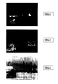
- FIG. 1 An example of an image obtained with an active system is shown in Figure 1. This image allows detect a vehicle, with a pedestrian on the road next to the vehicle. However, it is not possible to determine if the lights of this vehicle are the front or stop lamps of the vehicle. It is therefore not possible to know in which direction the vehicle is placed. This image also allows to see clear spots on the right of the road; these clear spots seem to be signs, but it is impossible to read the information on these signs.
- a sensor captures far infrared light, that is, the radiation having a wavelength of the order of 10 microns.
- Such systems can capture only infrared radiation emitted by the objects themselves. In other words, it is a measure of temperature of the elements of the road scene.
- the sensor captures the detected heat, such as infrared light.
- a example of an image obtained by a passive system is shown in the figure 2. This image makes it possible to visualize a first vehicle and, further, a second vehicle with pedestrians nearby. However, it is not possible to determine, in this image, whether the lights of these vehicles are the front or stop lamps. It is therefore not possible to know in which meaning are placed these vehicles.
- the active systems react too well to the sources lights such as the taillights of vehicles, the traffic lights on the road, etc. These fires, emitting infrared rays, dazzle the sensor and create a kind of halo of light all around the image of the considered object, which makes the outline of the object undefined. This glare is called "blooming".
- the road scene is seen at wavelengths that are outside the visible spectrum and therefore, by nature, foreign to the concept of color.
- the image of the scene of route obtained by these systems is therefore monochrome (ie black and white) with different levels of gray, the clear levels corresponding to the objects emitting or reflecting infrared and dark levels corresponding to objects that do not emit or reflect Infrared.
- monochrome image it is sometimes difficult to know precisely what kind of object it is. For example, on the images of Figures 1 and 2, it is not possible to detect whether they are front or rear of vehicles. Similarly, it is not possible to read the information written on the road signs.
- FIG. 3 An example of an image processed by video inversion is shown in Figure 3.
- the inversion video allows to better visualize the road scene and better imagine to what corresponds to each object of the road scene.
- the video inversion shows that the first vehicle comes in one direction reverse and that the second vehicle is parked in the same direction as the vehicle in which the system is mounted.
- Another treatment of the captured image proposes to colorize artificially the image of the road scene.
- This treatment consists of associate, at each gray level of the captured image, an artificial color and arbitrary.
- This operation is known, in image processing, under the name "application of a LUT (look up table)".
- the resulting image is called "Image in false colors” because the colors visible in the image are artificial colors that do not match the actual colors.
- the red color can be associated with a high gray level and the blue color at a very low gray level.
- Grayscale intermediates are associated with colors ranging from red to blue. It is thus understood that, for example, a fire located in front of the sensor will have a strongly red image (high gray level).
- the purpose of the invention is precisely to remedy the drawbacks of techniques previously discussed. To this end, it proposes a system of night vision to achieve an infrared image in color of the road scene in front of the vehicle. For this, the invention proposes to use a color sensor.
- the invention relates to a night vision system a road scene including at least one projection device emitting infrared light to the road scene and a first sensor to capture a first infrared image of the road scene, the sensor being a color sensor.
- the color sensor is a sensor detecting radiation at least in the visible, in particular essentially in the visible.
- the device emitting the infrared light may be, for example, chosen from one or more incandescent lamps, one or more electroluminescent diodes operating in the infrared or one or several laser diodes.
- the invention proposes to associate with the first sensor color, a second monochrome sensor. More specifically, this mode of preferred embodiment proposes a system comprising a second sensor monochrome to capture a second infrared image of the scene from route, the first image being a color image and the second image being a monochrome image.
- the monochrome sensor is a sensor detecting radiation at least in the wavelengths of the infrared. he can in addition detect other radiation, especially in the visible.
- a light source visible which may actually be the vehicle's headlamps, when these operate in particular in code beam.
- the invention relates to a color night vision system.
- This system includes a device for projecting infrared light towards the road scene, at the front of the vehicle, and at least one sensor to capture the image of this road scene, this sensor being a color sensor.
- this first sensor which is placed in or on the vehicle, is a color sensor capable of capturing a color image of the road scene. This image is an image in real colors.
- this color sensor is associated with a second sensor, which is monochrome.
- the monochrome sensor which is a sensor with high infrared sensitivity, capture an infrared image of the road scene.
- the color sensor captures a color image of the road scene.
- FIG. 7 shows a motor vehicle 10 equipped with the vision system nocturnal of the invention.
- This system comprises a projection device of infrared radiation 11, or projector.
- this headlamp may be installed, for example, in one of the front lights of the vehicle. It is also possible to install a projector in each fire before the vehicle. The projector can also be installed in a dwelling special, for example, between the two front lights of the vehicle.
- the system of the invention also comprises a color sensor 12.
- This color sensor can advantageously be combined with a sensor monochrome 13.
- both sensors are connected together so as to be synchronous or quasi-synchronous.
- Means of treatment images are connected to the sensors to process the images provided by these sensors.
- These processing means may be electronic type, mounted by example on a PCB dedicated to this treatment. They can also be of type computer, incorporated for example in the on-board computer of the vehicle.
- the monochrome sensor is chosen to have a high sensitivity to the rays that it can detect, particularly infrared radiation, especially in the near infrared.
- This sensor is monochrome because, in general, the Current monochrome sensors are significantly more sensitive than color sensors.
- a high sensitivity sensor can capture the most information possible, with maximum glare tolerated.
- a sensor is very sensitive to infrared when it is in particular capable of detecting radiation between 800 and 1200 nm, especially between 850 and 1100 nm, for example around 1000 to 1100 nm.
- a sensor with high sensitivity is able to detect a minimum number of watts, for example equivalent to the energy reflected by a tree trunk at 100 or 200 meters on which one sends an intensity of one or several tens of watts in the 800-1000 nm band. So, the image captured by this monochrome sensor is very clear and contains as much information as possible but, on the other hand, is dazzled by the enemy's sources,
- the sensitivity of the color sensor is not casting.
- a color sensor with a sensitivity lower than that of the monochrome sensor for example a sensitivity to 100 times lower.
- Such a color sensor, said to be insensitive can therefore capture radiation approximately 10 to 100 times what captures the sensor with high sensitivity without blooming.
- blooming the fact that an image has a spot that is saturated and that is larger than the image of the source on the sensor.
- the so-called sensitive sensor can not detect it about 30 meters, while the sensor said to high sensitivity could do it at 100 meters, when we choose a sensitivity ratio between the two sensors of about 100 (this is the distance squared that comes in).
- the image captured by the color sensor must not contain substantially no glare. All light sources should be one-off and not substantially halo. We can thus obtain an image showing the light sources real, without false information due to glare. These sources real lights are then shown in colors. The color image obtained is essentially composed of corresponding colored spots to light sources.
- FIG. 4 An example of a clear image, captured by the monochrome sensor, is shown in Figure 4.
- This image shows the different elements detected in the road scene by the high-sensitivity sensor. Among these elements, there are two halos of light 1a and 1b, a third halo of light projected on the ground 2, a pedestrian 3, white lines 8 and 9, panels 4 and 5 and white spots 6a, 6b, 7.
- FIG. 5 An example of a dark image, captured by the color sensor, is shown in Figure 5.
- This image shows only the elements that were the most dazzling in Figure 4.
- the halos 1a, 1b, 2 and 7 which are represented with hatching to symbolize the yellow color
- the panels 4 and 5 which are represented with mottled to symbolize the red color.
- the image taken by the color sensor would show yellow and other red elements.
- all other colors can also appear on the image ; for example, if a traffic light is present in the road scene, the bottom light appears green on the image and the intermediate orange light.
- the monochrome clear image and the dark color image are then combined to form one and the same image of the scene of road.
- This treatment can consist of an averaging operation of two images. In other words, an average is made between each pixel of the color image and the corresponding pixel of the monochrome image for form a color infrared image of the road scene.
- This new image includes both the color information provided by the color image and both the detailed information provided by the image monochrome.
- the fusion, or combination, of the monochrome clear image and the dark color image makes it possible to obtain a very sensitive image of the road scene (while being devoid of glare) and whose light sources and bright objects are colored.
- Figure 6 shows an example of a road scene image obtained by combining a clear monochrome image with an image dark color.
- the image of FIG. 6 is the image obtained in combining the image of Figure 4 with the image of Figure 5.
- the combination is an average pixel by pixel of the images of the Figures 4 and 5.
- this combination can be other than an average. It may be, for example, a weighted average or of the type described in the patent filed on March 29, 2002 in France under the deposit number 02-04170.
- a traffic light or fires rear lights or front lights or flashing lights could appear on the image with a color corresponding to the actual color said lights. It is therefore very easy for the driver to know which types of fires it is, to then be able to interpret the image and react in according to this interpretation.
- the invention thus combines a very sensitive black and white sensor with a less sensitive color sensor. It is also possible to use only one color sensor, chosen this time very sensitive.
- the invention also relates to the motor vehicle equipped of the night vision system according to the invention.
Abstract
Description
L'invention concerne un système de vision nocturne pour véhicule automobile. Ce système de vision nocturne, de type à infrarouge, permet de réaliser des images, au moins en partie en couleur, de la scène de route se déroulant devant le véhicule. L'invention concerne également un procédé de mise en oeuvre de ce système.The invention relates to a vehicle night vision system automobile. This night vision system, of the infrared type, allows to make images, at least partly in color, of the road scene drop down in front of the vehicle. The invention also relates to a method of implementation of this system.
L'invention trouve des applications dans le domaine des véhicules circulant sur route comme, par exemple, les véhicules automobiles. Elle trouve, en particulier, des applications dans le domaine de la vision nocturne pour ces véhicules.The invention finds applications in the field of vehicles on the road, such as motor vehicles. She finds, in particular, applications in the field of night vision for these vehicles.
Compte tenu du nombre important de véhicules circulant sur les routes, il est nécessaire de procurer, à ces véhicules et à leurs conducteurs, une vision de la route la mieux adaptée possible afin de réduire les risques d'accidents. En particulier la nuit, il est important que le conducteur puisse avoir une vision suffisamment détaillée de la route qui s'étend devant lui ainsi que des bas-côtés de cette route. Autrement dit, pour des questions de sécurité, on cherche à améliorer la vision nocturne de la scène de route par le conducteur du véhicule.Given the large number of vehicles traveling on roads, it is necessary to provide these vehicles and their drivers with a vision of the best adapted road to reduce risks accidents. Especially at night, it is important that the driver can have a sufficiently detailed vision of the road that extends before him as well that side of this road. In other words, for questions of safety, we seek to improve the night vision of the road scene by the driver of the vehicle.
Pour cela, il existe des systèmes de vision nocturne dans lesquels un dispositif d'éclairage, du type projecteur, émet un faisceau lumineux infrarouge en direction de la route, à l'avant du véhicule. Cette lumière infrarouge est réfléchie par les différents objets situés dans la scène de route. Cette réflexion de la lumière infrarouge est plus ou moins intense selon la nature de l'objet et sa distance par rapport au dispositif d'éclairage. Un capteur sensible aux rayonnements infrarouges, situé généralement dans le véhicule, assure une capture de ces rayonnements infrarouges. Il fournit alors une image infrarouge de la scène de route s'étendant devant le véhicule. Un tel système avec émission de rayons infrarouges, réflexion de ces rayons et capture des rayons réfléchis est appelé « système actif ». Il permet de détecter le proche infrarouge, c'est-à-dire les rayonnements ayant une longueur d'onde pouvant atteindre 1100 nm. Un exemple d'image obtenue avec un système actif est montré sur la figure 1. Cette image permet de détecter un véhicule, avec un piéton sur la route à coté du véhicule. Cependant, il n'est pas possible de déterminer si les lumières de ce véhicule sont les feux avant ou les feux stop du véhicule. Il n'est donc pas possible de savoir dans quel sens est placé le véhicule. Cette image permet également de voir des taches claires sur la droite de la route ; ces taches claires semblent être des panneaux de signalisation, mais il est impossible de lire l'information inscrite sur ces panneaux.For this, there are night vision systems in which a lighting device, of the projector type, emits a light beam infrared in the direction of the road, at the front of the vehicle. This light infrared is reflected by the different objects located in the scene of road. This reflection of infrared light is more or less intense depending on the nature of the object and its distance from the lighting device. A sensor sensitive to infrared radiation, usually located in the vehicle, ensures a capture of these infrared radiation. He gives then an infrared image of the road scene extending in front of the vehicle. Such a system with infrared emission, reflection of these rays and captures reflected rays is called "active system". he allows the detection of the near infrared, that is to say the radiation having a wavelength of up to 1100 nm. An example of an image obtained with an active system is shown in Figure 1. This image allows detect a vehicle, with a pedestrian on the road next to the vehicle. However, it is not possible to determine if the lights of this vehicle are the front or stop lamps of the vehicle. It is therefore not possible to know in which direction the vehicle is placed. This image also allows to see clear spots on the right of the road; these clear spots seem to be signs, but it is impossible to read the information on these signs.
Il existe également des systèmes permettant de détecter l'infrarouge lointain. Ces systèmes sont appelés des « systèmes passifs ». Dans ces systèmes, un capteur capture la lumière infrarouge lointaine, c'est-à-dire les rayonnements ayant une longueur d'onde de l'ordre de 10 µm. De tels systèmes permettent de capturer uniquement les rayonnements infrarouges émis par les objets eux-mêmes. En d'autres termes, il s'agit d'une mesure de température des éléments de la scène de route. Dans un tel système passif, le capteur capture la chaleur détectée, comme une lumière infrarouge. Un exemple d'une image obtenue par un système passif est montré sur la figure 2. Cette image permet de visualiser un premier véhicule et, plus loin, un second véhicule avec des piétons à proximité. Cependant, il n'est pas possible de déterminer, sur cette image, si les lumières de ces véhicules sont les feux avant ou les feux stop. Il n'est donc pas possible de savoir dans quel sens sont placés ces véhicules.There are also systems for detecting infrared distant. These systems are called "passive systems". In these systems, a sensor captures far infrared light, that is, the radiation having a wavelength of the order of 10 microns. Such systems can capture only infrared radiation emitted by the objects themselves. In other words, it is a measure of temperature of the elements of the road scene. In such a passive system, the sensor captures the detected heat, such as infrared light. A example of an image obtained by a passive system is shown in the figure 2. This image makes it possible to visualize a first vehicle and, further, a second vehicle with pedestrians nearby. However, it is not possible to determine, in this image, whether the lights of these vehicles are the front or stop lamps. It is therefore not possible to know in which meaning are placed these vehicles.
Tous ces systèmes présentent des inconvénients. En particulier, les systèmes passifs ne peuvent détecter les objets froids. Cet inconvénient est encore aggravé quand des objets mobiles, partageant le même espace que le véhicule, sont invisibles. C'est le cas notamment des voitures encore froides, qui ne roulent que depuis quelques instants et dont les glaces des feux arrières n'ont pas eu le temps de chauffer. En effet, la grande quantité de rayons infrarouges lointains émis par les lampes des feux arrières ne traversent ni le plastique ni le verre. De même, l'allumage des feux stop, des feux clignotants ou des feux de détresse n'échauffent pas instantanément la glace dudit feu. Ils sont donc indétectables par un système passif.All these systems have disadvantages. In particular, passive systems can not detect cold objects. This disadvantage is aggravated when moving objects, sharing the same space as the vehicle, are invisible. This is particularly the case for cars still cold, which have only been running for a few moments and whose ice rear lights did not have time to heat up. Indeed, the large quantity far infrared rays emitted by the taillight lamps through neither plastic nor glass. Likewise, the ignition of brake lights, flashing lights or hazard warning lights do not instantly heat up the ice of said fire. They are therefore undetectable by a passive system.
Au contraire, les systèmes actifs réagissent trop bien aux sources lumineuses telles que les feux arrières des véhicules, les feux tricolores sur la route, etc. Ces feux, en émettant des rayons infrarouges, éblouissent le capteur et créent une sorte de halo de lumière tout autour de l'image de l'objet considéré, ce qui rend le contour de l'objet indéfini. Cet éblouissement est appelé « blooming ».On the contrary, the active systems react too well to the sources lights such as the taillights of vehicles, the traffic lights on the road, etc. These fires, emitting infrared rays, dazzle the sensor and create a kind of halo of light all around the image of the considered object, which makes the outline of the object undefined. This glare is called "blooming".
Par ailleurs, avec ces systèmes actifs ou passifs, la scène de route est vue à des longueurs d'ondes qui sont extérieures au spectre du visible et donc, par nature, étrangères à la notion de couleur. L'image de la scène de route obtenue par ces systèmes est donc monochrome ( c'est-à-dire noir et blanc) avec différents niveaux de gris, les niveaux clairs correspondant aux objets émettant ou réfléchissant des infrarouges et les niveaux sombres correspondant aux objets n'émettant pas ou ne réfléchissant pas d'infrarouge. Or, avec une image monochrome, il est parfois difficile de savoir précisément de quel type d'objet il s'agit. Par exemple, sur les images des figures 1 et 2, il n'est pas possible de détecter s'il s'agit des feux avant ou arrière des véhicules. De même, il n'est possible de lire les informations inscrites sur les panneaux de signalisation.Moreover, with these active or passive systems, the road scene is seen at wavelengths that are outside the visible spectrum and therefore, by nature, foreign to the concept of color. The image of the scene of route obtained by these systems is therefore monochrome (ie black and white) with different levels of gray, the clear levels corresponding to the objects emitting or reflecting infrared and dark levels corresponding to objects that do not emit or reflect Infrared. But with a monochrome image, it is sometimes difficult to know precisely what kind of object it is. For example, on the images of Figures 1 and 2, it is not possible to detect whether they are front or rear of vehicles. Similarly, it is not possible to read the information written on the road signs.
Des systèmes actifs ou passifs tentent de remédier à ces inconvénients en traitant l'image capturée avant de l'afficher. L'un de ces traitements consiste en une inversion vidéo de l'image. Cette inversion vidéo permet de rendre clairs les objets détectés comme sombres et de rendre sombres les objets détectés comme brillants. Un exemple d'image traitée par inversion vidéo est montrée sur la figure 3. Dans cet exemple, l'inversion vidéo permet de mieux visualiser la scène de route et de mieux imaginer à quoi correspond chaque objet de la scène de route. Dans cet exemple, l'inversion vidéo permet de montrer que le premier véhicule vient en sens inverse et que le second véhicule est stationné dans le même sens que le véhicule dans lequel est monté le système.Active or passive systems attempt to remedy these disadvantages in processing the captured image before displaying it. One of these treatments consists of a video inversion of the image. This video inversion makes it possible to make the objects detected as dark and to make dark objects detected as bright. An example of an image processed by video inversion is shown in Figure 3. In this example, the inversion video allows to better visualize the road scene and better imagine to what corresponds to each object of the road scene. In this example, the video inversion shows that the first vehicle comes in one direction reverse and that the second vehicle is parked in the same direction as the vehicle in which the system is mounted.
Un autre traitement de l'image capturée propose de coloriser artificiellement l'image de la scène de route. Ce traitement consiste à associer, à chaque niveau de gris de l'image capturée, une couleur artificielle et arbitraire. Cette opération est connue, en traitement d'images, sous le nom d' «application d'une LUT (look up table) ». L'image obtenue est appellée « image en fausses couleurs » car les couleurs visibles sur l'image sont des couleurs artificielles qui ne correspondent pas aux couleurs réelles. Par exemple, la couleur rouge peut être associée à un niveau de gris élevé et la couleur bleue à un niveau de gris très faible. Les niveaux de gris intermédiaires sont associées à des couleurs déclinées entre le rouge et le bleu. On comprend ainsi que, par exemple, un feu situé en face du capteur aura une image forcement rouge (niveau de gris élevé). On ne pourra donc pas savoir s'il s'agit d'un feu de croisement d'un véhicule ou d'un feu stop. Il n'est donc pas possible d'interpréter exactement les objets situés dans la scène de route devant le véhicule. En d'autres termes, ces opérations de colorisation peuvent permettre d'améliorer la perception d'une image en révélant des informations qu'un simple affichage monochrome ne permet pas d'identifier. Elles restent, néanmoins, des artifices et ne rendent en rien compte de la couleur réelle des objets. Par exemple, dans le cas de la vision nocturne par infrarouge, des objets de la même couleur visible (par exemple vert) peuvent avoir des comportements radicalement opposés dans l'infrarouge. L'un peut apparaítre brillant ou clair parce que, outre les longueurs d'ondes lui donnant sa couleur verte, l'objet réfléchit l'infrarouge proche (système actif) ou émet, du fait de sa température, de l'infrarouge lointain (système passif). L'autre peut apparaitre sombre parce qu'il absorbe l'infrarouge proche et n'émet pas, du fait de sa faible température, d'infrarouge lointain.Another treatment of the captured image proposes to colorize artificially the image of the road scene. This treatment consists of associate, at each gray level of the captured image, an artificial color and arbitrary. This operation is known, in image processing, under the name "application of a LUT (look up table)". The resulting image is called "Image in false colors" because the colors visible in the image are artificial colors that do not match the actual colors. By example, the red color can be associated with a high gray level and the blue color at a very low gray level. Grayscale intermediates are associated with colors ranging from red to blue. It is thus understood that, for example, a fire located in front of the sensor will have a strongly red image (high gray level). We can not therefore not know if it is a passing light of a vehicle or a stop light. he It is therefore not possible to interpret exactly the objects in the road scene in front of the vehicle. In other words, these operations of colorization can improve the perception of an image by revealing information that a simple monochrome display does not allow identify. They remain, nevertheless, artifices and do not render anything account of the actual color of the objects. For example, in the case of vision by infrared, objects of the same visible color (for example green) may have radically different infrared. One can appear brilliant or clear because, besides the wavelengths giving it its green color, the object reflects infrared near (active system) or emits, because of its temperature, infrared distant (passive system). The other may appear dark because it absorbs the near infrared and does not emit, because of its low temperature, far infrared.
L'invention a justement pour but de remédier aux inconvénients des techniques exposées précédemment. A cette fin, elle propose un système de vision nocturne permettant de réaliser une image infrarouge en couleur de la scène de route située devant le véhicule. Pour cela, l'invention propose d'utiliser un capteur couleur.The purpose of the invention is precisely to remedy the drawbacks of techniques previously discussed. To this end, it proposes a system of night vision to achieve an infrared image in color of the road scene in front of the vehicle. For this, the invention proposes to use a color sensor.
De préférence, l'invention concerne un système de vision nocturne d'une scène de route comportant au moins un dispositif de projection émettant une lumière infrarouge vers la scène de route et un premier capteur pour capturer une première image infrarouge de la scène de route, le capteur étant un capteur en couleur.Preferably, the invention relates to a night vision system a road scene including at least one projection device emitting infrared light to the road scene and a first sensor to capture a first infrared image of the road scene, the sensor being a color sensor.
Avantageusement, le capteur couleur est un capteur détectant des rayonnements au moins dans le visible, notamment essentiellement dans le visible.Advantageously, the color sensor is a sensor detecting radiation at least in the visible, in particular essentially in the visible.
Le dispositif émettant la lumière infrarouge peut être, par exemple, choisi parmi une ou plusieurs lampes à incandescence, une ou plusieurs diodes électroluminescentes fonctionnant dans l'infrarouge ou une ou plusieurs diodes laser. The device emitting the infrared light may be, for example, chosen from one or more incandescent lamps, one or more electroluminescent diodes operating in the infrared or one or several laser diodes.
Dans un autre mode de réalisation préféré de l'invention, on cherche également à éviter l'éblouissement que l'on obtient au moyen d'un système actif classique. Pour cela, l'invention propose d'associer au premier capteur couleur, un second capteur monochrome. Plus précisément, ce mode de réalisation préféré propose un système comportant un second capteur monochrome pour capturer une seconde image infrarouge de la scène de route, la première image étant une image couleur et la seconde image étant une image monochrome.In another preferred embodiment of the invention, one seeks also to avoid glare that is achieved by means of a system classic asset. For this, the invention proposes to associate with the first sensor color, a second monochrome sensor. More specifically, this mode of preferred embodiment proposes a system comprising a second sensor monochrome to capture a second infrared image of the scene from route, the first image being a color image and the second image being a monochrome image.
Avantageusement, le capteur monochrome est un capteur détectant les rayonnements au moins dans les longueurs d'onde de l'infrarouge. Il peut en plus détecter d'autres rayonnements, notamment dans le visible.Advantageously, the monochrome sensor is a sensor detecting radiation at least in the wavelengths of the infrared. he can in addition detect other radiation, especially in the visible.
Optionnellement, on peut aussi avoir recours à une source de lumière visible, qui peut en fait être les projecteurs du véhicule, quand ceux-ci fonctionnent notamment en faisceau code.Optionally, we can also use a light source visible, which may actually be the vehicle's headlamps, when these operate in particular in code beam.
L'invention concerne également un procédé pour mettre en oeuvre le système de vision nocturne de l'invention. Il s'agit d'un procédé de vision nocturne d'une scène de route, dans lequel un faisceau lumineux infrarouge est émis en direction de la scène de route, avec les opérations suivantes :
- capture d'une première image en couleur de la scène de route,
- capture d'une seconde image infrarouge monochrome de la scène de route,
- combinaison des première et seconde images de la scène de route, et
- obtention d'une image infrarouge en couleur de la scène de route.
- capture of a first color image of the road scene,
- capture a second monochrome infrared image of the road scene,
- combination of the first and second images of the road scene, and
- obtaining an infrared image in color of the road scene.
L'invention concerne un système de vision nocturne en couleur. Ce système comporte un dispositif pour projeter une lumière infrarouge vers la scène de route, à l'avant du véhicule, et au moins un capteur pour capturer l'image de cette scène de route, ce capteur étant un capteur couleur. En d'autres termes, ce premier capteur, qui est placé dans ou sur le véhicule, est un capteur couleur capable de capturer une image en couleur de la scène de route. Cette image est une image en couleurs réelles.The invention relates to a color night vision system. This system includes a device for projecting infrared light towards the road scene, at the front of the vehicle, and at least one sensor to capture the image of this road scene, this sensor being a color sensor. In in other words, this first sensor, which is placed in or on the vehicle, is a color sensor capable of capturing a color image of the road scene. This image is an image in real colors.
Dans un mode de réalisation préféré de l'invention, ce capteur couleur est associé à un second capteur, qui lui est monochrome. De cette façon, le capteur monochrome, qui est un capteur à haute sensibilité infrarouge, capture une image infrarouge de la scène de route. De façon simultanée ou quasi-simultanée, le capteur couleur capture une image en couleur de la scène de route. Ces deux images, en couleur et infrarouge, sont ensuite combinées pour former une seule et même image infrarouge en couleur de la scène de route.In a preferred embodiment of the invention, this color sensor is associated with a second sensor, which is monochrome. In this way, the monochrome sensor, which is a sensor with high infrared sensitivity, capture an infrared image of the road scene. Simultaneously or near-simultaneous, the color sensor captures a color image of the road scene. These two images, in color and infrared, are then combined to form one and the same infrared color image of the road scene.
Un exemple du système de l'invention est schématisé sur la figure 7.
Cette figure 7 montre un véhicule automobile 10 muni du système de vision
nocturne de l'invention. Ce système comporte un dispositif de projection de
rayonnements infrarouges 11, ou projecteur. Comme montré sur la figure 7,
ce projecteur peut être installé, par exemple, dans un des feux avant du
véhicule. Il est possible également d'installer un projecteur dans chaque feu
avant du véhicule. Le projecteur peut aussi être installé dans un logement
spécial, par exemple, entre les deux feux avant du véhicule.An example of the system of the invention is shown schematically in FIG.
This figure 7 shows a
Le système de l'invention comporte aussi un capteur couleur 12. Ce
capteur couleur peut, avantageusement, être combiné avec un capteur
monochrome 13. Dans ce cas, les deux capteurs sont connectés ensemble
de façon à être synchrones ou quasi-synchrones. Des moyens de traitement
d'images, non représentés sur la figure par mesure de simplification, sont
reliés aux capteurs pour traiter les images fournies par ces capteurs. Ces
moyens de traitement peuvent être de type électroniques, montés par
exemple sur un PCB dédié à ce traitement. Ils peuvent aussi être de type
informatique, incorporés par exemple dans l'ordinateur de bord du véhicule.The system of the invention also comprises a
Dans le mode de réalisation préféré, le capteur monochrome est choisi de façon à avoir une haute sensibilité aux rayons qu'il peut détecter, notamment aux rayonnements infrarouges, notamment dans le proche infrarouge. Ce capteur est monochrome car, d'une façon générale, les capteurs monochromes actuels sont nettement plus sensibles que les capteurs couleurs. Un capteur à haute sensibilité peut capturer le plus d'informations possible, avec un éblouissement maximum toléré. On considère qu'un capteur est très sensible aux infrarouges lorsqu'il est notamment capable de détecter des rayonnements entre 800 et 1200 nm, notamment entre 850 et 1100 nm, par exemple aux alentours des 1000 à 1100 nm.In the preferred embodiment, the monochrome sensor is chosen to have a high sensitivity to the rays that it can detect, particularly infrared radiation, especially in the near infrared. This sensor is monochrome because, in general, the Current monochrome sensors are significantly more sensitive than color sensors. A high sensitivity sensor can capture the most information possible, with maximum glare tolerated. We considers that a sensor is very sensitive to infrared when it is in particular capable of detecting radiation between 800 and 1200 nm, especially between 850 and 1100 nm, for example around 1000 to 1100 nm.
Pour exprimer plus concrètement ce à quoi correspond une telle sensibilité, on peut donner l'exemple suivant :un capteur à haute sensibilité est capable de détecter un nombre minimum de watts, par exemple équivalent à l'énergie réfléchie par un tronc arbre à 100 ou 200 mètres sur lequel on envoie une intensité d'une ou plusieurs dizaines de watts dans la bande 800-1000 nm. Ainsi, l'image capturée par ce capteur monochrome est très claire et contient le plus d'informations possible mais, par contre, elle subit l'éblouissement des sources adverses,To express more concretely what it is sensitivity, we can give the following example: a sensor with high sensitivity is able to detect a minimum number of watts, for example equivalent to the energy reflected by a tree trunk at 100 or 200 meters on which one sends an intensity of one or several tens of watts in the 800-1000 nm band. So, the image captured by this monochrome sensor is very clear and contains as much information as possible but, on the other hand, is dazzled by the enemy's sources,
Au contraire, la sensibilité du capteur couleur n'est pas prépondérante. On peut donc utiliser un capteur couleur ayant une sensibilité inférieure à celle du capteur monochrome, par exemple une sensibilité 10 à 100 fois moins élevée. Un tel capteur couleur, dit peu sensible, peut donc capturer des rayonnements approximativement 10 à 100 fois supérieurs à ce que capte le capteur à haute sensibilité sans blooming. On comprend par « blooming » le fait qu'une image présente une tache qui est saturée et qui est plus grande que celle de l'image de la source sur le capteur. Pour prendre un exemple concret, si on reprend le tronc d'arbre mentionné plus haut, le capteur dit peu sensible ne pourra par exemple le détecter qu'à environ 30 mètres, alors que le capteur dit à haute sensibilité pouvait le faire à 100 mètres, quand on choisit un rapport de sensibilité entre les deux capteurs d'environ 100 (c'est la distance au carré qui intervient). On the contrary, the sensitivity of the color sensor is not casting. We can therefore use a color sensor with a sensitivity lower than that of the monochrome sensor, for example a sensitivity to 100 times lower. Such a color sensor, said to be insensitive, can therefore capture radiation approximately 10 to 100 times what captures the sensor with high sensitivity without blooming. We understand by "Blooming" the fact that an image has a spot that is saturated and that is larger than the image of the source on the sensor. For take a concrete example, if we take the tree trunk mentioned more high, the so-called sensitive sensor can not detect it about 30 meters, while the sensor said to high sensitivity could do it at 100 meters, when we choose a sensitivity ratio between the two sensors of about 100 (this is the distance squared that comes in).
L'image capturée par le capteur couleur ne doit comporter substantiellement aucun éblouissement. Toutes les sources de lumière intenses doivent être ponctuelles et ne pas comporter substantiellement de halo. On peut ainsi obtenir une image montrant les sources lumineuses réelles, sans fausse information due à l'éblouissement. Ces sources lumineuses réelles sont alors montrées en couleurs. L'image couleur obtenue est essentiellement composée de taches colorées correspondant aux sources lumineuses.The image captured by the color sensor must not contain substantially no glare. All light sources should be one-off and not substantially halo. We can thus obtain an image showing the light sources real, without false information due to glare. These sources real lights are then shown in colors. The color image obtained is essentially composed of corresponding colored spots to light sources.
Le système de vision nocturne du mode de réalisation préféré de l'invention est basé sur la capture des deux images synchrones ou quasi synchrones d'une même scène de route, avec des paramètres d'exposition sensiblement différents de sorte que :
- l'une des images est aussi claire que le permet le capteur monochrome afin de détecter le plus d'informations possible, et
- l'autre image est beaucoup plus sombre afin que seuls les éléments susceptibles d'éblouir l'image claire soient notablement visibles, et en couleurs.
- one of the images is as clear as the monochrome sensor allows to detect as much information as possible, and
- the other image is much darker so that only the elements likely to dazzle the clear image are noticeably visible, and in color.
Un exemple d'image claire, capturée par le capteur monochrome, est
représenté sur la figure 4. Cette image montre les différents éléments
détectés dans la scène de route par le capteur à haute sensibilité. Parmi ces
éléments, on distingue deux halos de lumière 1a et 1b, un troisième halo de
lumière projectée au sol 2, un piéton 3, des lignes blanches 8 et 9, des
panneaux 4 et 5 et des taches blanches 6a, 6b, 7.An example of a clear image, captured by the monochrome sensor, is
shown in Figure 4. This image shows the different elements
detected in the road scene by the high-sensitivity sensor. Among these
elements, there are two halos of light 1a and 1b, a third halo of
light projected on the
Un exemple d'image sombre, capturée par le capteur couleur, est
représenté sur la figure 5. Cette image montre uniquement les éléments qui
étaient les plus éblouissant sur la figure 4. Parmi ces éléments, on voit les
halos 1a, 1b, 2 et 7 qui sont représentés avec des hachures pour symboliser
la couleur jaune et les panneaux 4 et 5 qui sont représentés avec des
mouchetés pour symboliser la couleur rouge. En effet, sur une image réelle
d'une scène de route correspondant à celle de la figure 1, l'image prise par le
capteur couleur montrerait des éléments jaunes et d'autres rouges. On
comprendra que toutes les autres couleurs peuvent aussi apparaítre sur
l'image ; par exemple, si un feu tricolore est présent dans la scène de route,
le feu du bas apparaít vert sur l'image et le feu intermédiaire orange. An example of a dark image, captured by the color sensor, is
shown in Figure 5. This image shows only the elements that
were the most dazzling in Figure 4. Among these elements, we see the
Cette image sombre de la figure 5 permet, notamment, de faire apparaítre l'inscription des panneaux de signalisation. On peut ainsi savoir qu'il s'agit d'un panneau de stop.This dark image of Figure 5 makes it possible, in particular, to appear the inscription of the signs. We can know it is a stop sign.
L'image claire monochrome et l'image sombre en couleur sont ensuite combinées pour ne former qu'une seule et même image de la scène de route. Ce traitement peut consister en une opération de moyennage des deux images. Autrement dit, on réalise une moyenne entre chaque pixel de l'image couleur et le pixel correspondant de l'image monochrome pour former une image infrarouge en couleur de la scène de route. Cette nouvelle image comporte à la fois les informations relatives aux couleurs fournies par l'image en couleur et à la fois les informations détaillées fournies par l'image monochrome.The monochrome clear image and the dark color image are then combined to form one and the same image of the scene of road. This treatment can consist of an averaging operation of two images. In other words, an average is made between each pixel of the color image and the corresponding pixel of the monochrome image for form a color infrared image of the road scene. This new image includes both the color information provided by the color image and both the detailed information provided by the image monochrome.
La fusion, ou combinaison, de l'image claire monochrome et de l'image sombre en couleur permettent d'obtenir une image très sensible de la scène de route (tout en étant dénuée de tout éblouissement) et dont les sources de lumière et les objets brillants sont colorés.The fusion, or combination, of the monochrome clear image and the dark color image makes it possible to obtain a very sensitive image of the road scene (while being devoid of glare) and whose light sources and bright objects are colored.
La figure 6 représente un exemple d'une image de scène de route obtenue par combinaison d'une image monochrome claire avec une image couleur sombre. Autrement dit, l'image de la figure 6 est l'image obtenue en combinant l'image de la figure 4 avec l'image de la figure 5. Dans cet exemple, la combinaison est une moyenne pixel par pixel des images des figures 4 et 5. Cette combinaison peut toutefois être autre qu'une moyenne. Ce peut être, par exemple, une moyenne pondérée ou bien du type décrit dans le brevet déposé le 29 mars 2002 en France sous le numéro de dépôt 02-04170.Figure 6 shows an example of a road scene image obtained by combining a clear monochrome image with an image dark color. In other words, the image of FIG. 6 is the image obtained in combining the image of Figure 4 with the image of Figure 5. In this example, the combination is an average pixel by pixel of the images of the Figures 4 and 5. However, this combination can be other than an average. It may be, for example, a weighted average or of the type described in the patent filed on March 29, 2002 in France under the deposit number 02-04170.
Cette image combinée de la figure 6 montre à la fois les éléments qui
étaient peu brillants sur la figure 4 et les éléments colorés de la figure 5. On
voit ainsi le piéton 3 et les lignes blanches 8 et 9. On voit également les feux
avant jaunes 1 a et 1 b du véhicule venant en sens inverse, le reflet sur le sol
2 de ces feux avant et les panneaux de signalisation rouges 4 et 5 avec
l'inscription « Stop » sur le panneau 4.This combined image of Figure 6 shows both the elements that
were not very bright in Figure 4 and the colored elements in Figure 5.
thus sees the
Dans un autre exemple de scène de route, un feu tricolore ou des feux stop arrières ou des feux d'éclairage avant ou des feux clignotants pourraient apparaitre sur l'image avec une couleur correspondant à la couleur réelle desdits feux. Il est donc très facile pour le conducteur de savoir de quels types de feux il s'agit, de pouvoir alors interpréter l'image et réagir en fonction de cette interprétation.In another example of a road scene, a traffic light or fires rear lights or front lights or flashing lights could appear on the image with a color corresponding to the actual color said lights. It is therefore very easy for the driver to know which types of fires it is, to then be able to interpret the image and react in according to this interpretation.
L'invention combine donc un capteur noir et blanc très sensible avec un capteur couleur moins sensible. Il est également possible de n'utiliser qu'un seul capteur couleur, choisi alors cette fois très sensible.The invention thus combines a very sensitive black and white sensor with a less sensitive color sensor. It is also possible to use only one color sensor, chosen this time very sensitive.
L'invention concerne également le véhicule automobile équipé du système de vision nocturne selon l'invention.The invention also relates to the motor vehicle equipped of the night vision system according to the invention.
Claims (10)
Applications Claiming Priority (2)
| Application Number | Priority Date | Filing Date | Title |
|---|---|---|---|
| FR0308583A FR2857463B1 (en) | 2003-07-11 | 2003-07-11 | INFRARED NIGHT VISIT SYSTEM IN COLOR. |
| FR0308583 | 2003-07-11 |
Publications (2)
| Publication Number | Publication Date |
|---|---|
| EP1496689A1 true EP1496689A1 (en) | 2005-01-12 |
| EP1496689B1 EP1496689B1 (en) | 2008-03-12 |
Family
ID=33443281
Family Applications (1)
| Application Number | Title | Priority Date | Filing Date |
|---|---|---|---|
| EP04291748A Not-in-force EP1496689B1 (en) | 2003-07-11 | 2004-07-08 | Infrared night vision device for generating coloured images |
Country Status (6)
| Country | Link |
|---|---|
| US (1) | US7358496B2 (en) |
| EP (1) | EP1496689B1 (en) |
| JP (1) | JP2005136952A (en) |
| AT (1) | ATE389299T1 (en) |
| DE (1) | DE602004012353T2 (en) |
| FR (1) | FR2857463B1 (en) |
Cited By (5)
| Publication number | Priority date | Publication date | Assignee | Title |
|---|---|---|---|---|
| EP1887785A1 (en) * | 2006-08-04 | 2008-02-13 | Nederlandse Organisatie voor Toegepast-Natuuurwetenschappelijk Onderzoek TNO | Method and system for converting at least one first-spectrum image into a second-spectrum image |
| EP2128521A1 (en) | 2008-05-27 | 2009-12-02 | Valeo Vision | Automobile headlight capable of emitting an adjustable light beam. |
| CN103380447A (en) * | 2011-03-01 | 2013-10-30 | 奥托立夫开发公司 | A driver assistance system and method for a motor vehicle |
| EP3147821A1 (en) * | 2015-09-28 | 2017-03-29 | Valeo Vision | Lighting system and method |
| WO2018215066A1 (en) | 2017-05-24 | 2018-11-29 | HELLA GmbH & Co. KGaA | Method and system for automatically colorizing night-vision images |
Families Citing this family (21)
| Publication number | Priority date | Publication date | Assignee | Title |
|---|---|---|---|---|
| US7427758B2 (en) | 2003-05-28 | 2008-09-23 | Opto-Knowledge Systems, Inc. | Cryogenically cooled adjustable apertures for infra-red cameras |
| US7319805B2 (en) * | 2003-10-06 | 2008-01-15 | Ford Motor Company | Active night vision image intensity balancing system |
| DE10348109A1 (en) * | 2003-10-16 | 2005-05-19 | Bayerische Motoren Werke Ag | Method and device for visualizing a vehicle environment |
| FR2884637B1 (en) * | 2005-04-19 | 2007-06-29 | Valeo Vision Sa | METHOD OF DETECTING NIGHT MIST AND SYSTEM FOR IMPLEMENTING SAID METHOD |
| ITMN20050049A1 (en) * | 2005-07-18 | 2007-01-19 | Balzanelli Sonia | VISUAL DEVICE FOR VEHICLES IN DIFFICULT CLIMATE-ENVIRONMENTAL CONDITIONS |
| US7609291B2 (en) * | 2005-12-07 | 2009-10-27 | Avago Technologies Ecbu Ip (Singapore) Pte. Ltd. | Device and method for producing an enhanced color image using a flash of infrared light |
| FR2898310B1 (en) * | 2006-03-10 | 2009-04-17 | Valeo Vision Sa | METHOD FOR CONTROLLING AUTOMATIC VEHICLE PROJECTOR SWITCHING. |
| US8164813B1 (en) | 2007-06-16 | 2012-04-24 | Opto-Knowledge Systems, Inc. | Non-circular continuous variable aperture or shutter for infrared cameras |
| US8810651B2 (en) * | 2007-09-26 | 2014-08-19 | Honeywell International, Inc | Pseudo-color covert night vision security digital camera system |
| JP5200861B2 (en) * | 2007-12-10 | 2013-06-05 | 富士通株式会社 | Sign judging device and sign judging method |
| KR20090120159A (en) * | 2008-05-19 | 2009-11-24 | 삼성전자주식회사 | Apparatus and method for combining images |
| US8416302B2 (en) * | 2009-02-10 | 2013-04-09 | Microsoft Corporation | Low-light imaging augmented with non-intrusive lighting |
| US8836793B1 (en) | 2010-08-13 | 2014-09-16 | Opto-Knowledge Systems, Inc. | True color night vision (TCNV) fusion |
| EP2634747A1 (en) | 2012-02-29 | 2013-09-04 | Flir Systems AB | A method and system for projecting a visible representation of infrared radiation |
| DE102012014994B4 (en) | 2012-07-28 | 2024-02-22 | Volkswagen Aktiengesellschaft | Image processing method for a digital stereo camera arrangement |
| WO2014197109A2 (en) | 2013-03-22 | 2014-12-11 | Seiko Epson Corporation | Infrared video display eyewear |
| FR3010941B1 (en) * | 2013-09-26 | 2017-01-13 | Valeo Vision | DEVICE AND METHOD FOR DRIVING ASSISTANCE |
| WO2016018395A1 (en) * | 2014-07-31 | 2016-02-04 | Hewlett-Packard Development Company, L.P. | Document region detection |
| DE102015217253A1 (en) * | 2015-09-10 | 2017-03-16 | Robert Bosch Gmbh | Environment detecting device for a vehicle and method for capturing an image by means of an environment detecting device |
| JP6439763B2 (en) * | 2016-08-23 | 2018-12-19 | トヨタ自動車株式会社 | Image processing device |
| JP7252755B2 (en) * | 2018-12-27 | 2023-04-05 | 株式会社小糸製作所 | Active sensors, object identification systems, vehicles, vehicle lighting |
Citations (5)
| Publication number | Priority date | Publication date | Assignee | Title |
|---|---|---|---|---|
| US5001558A (en) * | 1985-06-11 | 1991-03-19 | General Motors Corporation | Night vision system with color video camera |
| US5910816A (en) * | 1995-06-07 | 1999-06-08 | Stryker Corporation | Imaging system with independent processing of visible an infrared light energy |
| US6150930A (en) * | 1992-08-14 | 2000-11-21 | Texas Instruments Incorporated | Video equipment and method to assist motor vehicle operators |
| US6429429B1 (en) * | 2000-06-22 | 2002-08-06 | Ford Global Technologies, Inc. | Night vision system utilizing a diode laser illumination module and a method related thereto |
| US20020118282A1 (en) * | 2001-02-20 | 2002-08-29 | Yoshiyuki Nakamura | On-vehicle video camera |
Family Cites Families (9)
| Publication number | Priority date | Publication date | Assignee | Title |
|---|---|---|---|---|
| US5729016A (en) * | 1994-04-12 | 1998-03-17 | Hughes Aircraft Company | Low cost night vision system for nonmilitary surface vehicles |
| US6891563B2 (en) * | 1996-05-22 | 2005-05-10 | Donnelly Corporation | Vehicular vision system |
| US6614579B2 (en) * | 1999-10-22 | 2003-09-02 | Gentex Corporation | Proximity switch and vehicle rearview mirror assembly incorporating the same and having a transparent housing |
| US6815680B2 (en) * | 2002-06-05 | 2004-11-09 | Raytheon Company | Method and system for displaying an image |
| AU2003247148A1 (en) * | 2002-08-05 | 2004-02-23 | Elbit Systems Ltd. | Vehicle mounted night vision imaging system and method |
| US6795237B1 (en) * | 2003-06-02 | 2004-09-21 | Ford Motor Company | Overhead console active night vision system for an interior cabin of a vehicle |
| US7358498B2 (en) * | 2003-08-04 | 2008-04-15 | Technest Holdings, Inc. | System and a method for a smart surveillance system |
| US7526103B2 (en) * | 2004-04-15 | 2009-04-28 | Donnelly Corporation | Imaging system for vehicle |
| US20050247862A1 (en) * | 2004-05-05 | 2005-11-10 | Lear Corporation | Active night vision system with fully synchronized light source and receiver |
-
2003
- 2003-07-11 FR FR0308583A patent/FR2857463B1/en not_active Expired - Fee Related
-
2004
- 2004-07-08 DE DE602004012353T patent/DE602004012353T2/en active Active
- 2004-07-08 AT AT04291748T patent/ATE389299T1/en not_active IP Right Cessation
- 2004-07-08 EP EP04291748A patent/EP1496689B1/en not_active Not-in-force
- 2004-07-09 US US10/888,812 patent/US7358496B2/en active Active
- 2004-07-12 JP JP2004204256A patent/JP2005136952A/en active Pending
Patent Citations (5)
| Publication number | Priority date | Publication date | Assignee | Title |
|---|---|---|---|---|
| US5001558A (en) * | 1985-06-11 | 1991-03-19 | General Motors Corporation | Night vision system with color video camera |
| US6150930A (en) * | 1992-08-14 | 2000-11-21 | Texas Instruments Incorporated | Video equipment and method to assist motor vehicle operators |
| US5910816A (en) * | 1995-06-07 | 1999-06-08 | Stryker Corporation | Imaging system with independent processing of visible an infrared light energy |
| US6429429B1 (en) * | 2000-06-22 | 2002-08-06 | Ford Global Technologies, Inc. | Night vision system utilizing a diode laser illumination module and a method related thereto |
| US20020118282A1 (en) * | 2001-02-20 | 2002-08-29 | Yoshiyuki Nakamura | On-vehicle video camera |
Cited By (10)
| Publication number | Priority date | Publication date | Assignee | Title |
|---|---|---|---|---|
| EP1887785A1 (en) * | 2006-08-04 | 2008-02-13 | Nederlandse Organisatie voor Toegepast-Natuuurwetenschappelijk Onderzoek TNO | Method and system for converting at least one first-spectrum image into a second-spectrum image |
| WO2008016305A3 (en) * | 2006-08-04 | 2008-05-29 | Tno | Method and system for converting at least one first-spectrum image into a second-spectrum image |
| US8478028B2 (en) | 2006-08-04 | 2013-07-02 | Nederlandse Organisatie Voor Toegepast-Natuurwetenschappelijk Onderzoek Tno | Method and system for converting at least one first-spectrum image into a second-spectrum image |
| EP2128521A1 (en) | 2008-05-27 | 2009-12-02 | Valeo Vision | Automobile headlight capable of emitting an adjustable light beam. |
| EP2957825A1 (en) | 2008-05-27 | 2015-12-23 | Valeo Vision | Motor vehicle headlamp capable of emitting an adjustable light beam |
| CN103380447A (en) * | 2011-03-01 | 2013-10-30 | 奥托立夫开发公司 | A driver assistance system and method for a motor vehicle |
| CN103380447B (en) * | 2011-03-01 | 2015-11-25 | 奥托立夫开发公司 | For driver assistance system and the method for motor vehicles |
| EP3147821A1 (en) * | 2015-09-28 | 2017-03-29 | Valeo Vision | Lighting system and method |
| FR3041739A1 (en) * | 2015-09-28 | 2017-03-31 | Valeo Vision | LIGHTING SYSTEM AND METHOD |
| WO2018215066A1 (en) | 2017-05-24 | 2018-11-29 | HELLA GmbH & Co. KGaA | Method and system for automatically colorizing night-vision images |
Also Published As
| Publication number | Publication date |
|---|---|
| JP2005136952A (en) | 2005-05-26 |
| DE602004012353D1 (en) | 2008-04-24 |
| US20050040333A1 (en) | 2005-02-24 |
| US7358496B2 (en) | 2008-04-15 |
| EP1496689B1 (en) | 2008-03-12 |
| DE602004012353T2 (en) | 2009-03-12 |
| ATE389299T1 (en) | 2008-03-15 |
| FR2857463B1 (en) | 2005-09-02 |
| FR2857463A1 (en) | 2005-01-14 |
Similar Documents
| Publication | Publication Date | Title |
|---|---|---|
| EP1496689B1 (en) | Infrared night vision device for generating coloured images | |
| EP0455524B1 (en) | Illumination and display system for vehicles | |
| EP1715456B1 (en) | Method for detecting night fog and system implementing said method | |
| EP1442927B1 (en) | Method for modulated lighting of a road and headlamp using such a method | |
| FR3027654B1 (en) | LIGHTING AND / OR SIGNALING SYSTEM COMPRISING TELEMETRY MEANS | |
| EP2056093B1 (en) | Method for detection of a phenomenon perturbating the visibility for a vehicule | |
| FR2721872A1 (en) | Head-up display device for producing additional image of road ahead | |
| FR3068314B1 (en) | LIGHT SYSTEM FOR MOTOR VEHICLE | |
| EP2382783A1 (en) | Perimeter security system for the active analysis of images reflected by a mirror array onto a video camera | |
| EP2415636A2 (en) | Lighting system for a vehicle | |
| FR3043168A1 (en) | DEVICE FOR PROJECTING THE LIGHT BEAM OF A MOTOR VEHICLE CONFIGURED TO PROJECT A PIXELIZED IMAGE | |
| FR3034728A1 (en) | LIGHTING SYSTEM FOR MOTOR VEHICLE | |
| JP6555569B2 (en) | Image processing apparatus, mobile device control system, and image processing program | |
| EP3258746A2 (en) | Protection of a light module comprising a laser source | |
| FR2730035A1 (en) | Infra-red headlamp to aid night vision in motor vehicle | |
| EP3059121B1 (en) | Generation and remote processing of photometry | |
| EP3074922B1 (en) | System and method for rendering night images for a car vehicle | |
| EP1580074B1 (en) | Method for detecting a wet road and illumination system to implement the method | |
| FR3053758A1 (en) | LIGHTING AND / OR SIGNALING DEVICE FOR MOTOR VEHICLE | |
| FR3090073A1 (en) | Motor vehicle light module | |
| EP1812262A1 (en) | Motor vehicle low-beam headlight system | |
| FR3079614A1 (en) | METHOD AND DEVICE FOR MEASURING VISIBILITY CONDITIONS | |
| FR3105143A1 (en) | Method for detecting a local condition of the road on which a motor vehicle is traveling | |
| FR3099542A1 (en) | Lighting and signaling set for motor vehicles incorporating a fog lamp | |
| FR3056488A1 (en) | METHOD FOR CONTROLLING AUTOMATIC DISPLAY OF A PICTOGRAM REPRESENTING A LILT SITUATION BY A NEXT VEHICLE |
Legal Events
| Date | Code | Title | Description |
|---|---|---|---|
| PUAI | Public reference made under article 153(3) epc to a published international application that has entered the european phase |
Free format text: ORIGINAL CODE: 0009012 |
|
| AK | Designated contracting states |
Kind code of ref document: A1 Designated state(s): AT BE BG CH CY CZ DE DK EE ES FI FR GB GR HU IE IT LI LU MC NL PL PT RO SE SI SK TR |
|
| AX | Request for extension of the european patent |
Extension state: AL HR LT LV MK |
|
| 17P | Request for examination filed |
Effective date: 20050610 |
|
| AKX | Designation fees paid |
Designated state(s): AT BE BG CH CY CZ DE DK EE ES FI FR GB GR HU IE IT LI LU MC NL PL PT RO SE SI SK TR |
|
| GRAP | Despatch of communication of intention to grant a patent |
Free format text: ORIGINAL CODE: EPIDOSNIGR1 |
|
| RIN1 | Information on inventor provided before grant (corrected) |
Inventor name: HUE, DAVID Inventor name: FLEURY, BENOIST Inventor name: HIDDEN, PHILIPPE |
|
| GRAS | Grant fee paid |
Free format text: ORIGINAL CODE: EPIDOSNIGR3 |
|
| GRAA | (expected) grant |
Free format text: ORIGINAL CODE: 0009210 |
|
| AK | Designated contracting states |
Kind code of ref document: B1 Designated state(s): AT BE BG CH CY CZ DE DK EE ES FI FR GB GR HU IE IT LI LU MC NL PL PT RO SE SI SK TR |
|
| REG | Reference to a national code |
Ref country code: GB Ref legal event code: FG4D Free format text: NOT ENGLISH |
|
| REG | Reference to a national code |
Ref country code: CH Ref legal event code: EP |
|
| REG | Reference to a national code |
Ref country code: IE Ref legal event code: FG4D Free format text: LANGUAGE OF EP DOCUMENT: FRENCH |
|
| REF | Corresponds to: |
Ref document number: 602004012353 Country of ref document: DE Date of ref document: 20080424 Kind code of ref document: P |
|
| PG25 | Lapsed in a contracting state [announced via postgrant information from national office to epo] |
Ref country code: FI Free format text: LAPSE BECAUSE OF FAILURE TO SUBMIT A TRANSLATION OF THE DESCRIPTION OR TO PAY THE FEE WITHIN THE PRESCRIBED TIME-LIMIT Effective date: 20080312 |
|
| PG25 | Lapsed in a contracting state [announced via postgrant information from national office to epo] |
Ref country code: AT Free format text: LAPSE BECAUSE OF FAILURE TO SUBMIT A TRANSLATION OF THE DESCRIPTION OR TO PAY THE FEE WITHIN THE PRESCRIBED TIME-LIMIT Effective date: 20080312 |
|
| NLV1 | Nl: lapsed or annulled due to failure to fulfill the requirements of art. 29p and 29m of the patents act | ||
| PG25 | Lapsed in a contracting state [announced via postgrant information from national office to epo] |
Ref country code: SI Free format text: LAPSE BECAUSE OF FAILURE TO SUBMIT A TRANSLATION OF THE DESCRIPTION OR TO PAY THE FEE WITHIN THE PRESCRIBED TIME-LIMIT Effective date: 20080312 Ref country code: PL Free format text: LAPSE BECAUSE OF FAILURE TO SUBMIT A TRANSLATION OF THE DESCRIPTION OR TO PAY THE FEE WITHIN THE PRESCRIBED TIME-LIMIT Effective date: 20080312 |
|
| REG | Reference to a national code |
Ref country code: IE Ref legal event code: FD4D |
|
| PG25 | Lapsed in a contracting state [announced via postgrant information from national office to epo] |
Ref country code: ES Free format text: LAPSE BECAUSE OF FAILURE TO SUBMIT A TRANSLATION OF THE DESCRIPTION OR TO PAY THE FEE WITHIN THE PRESCRIBED TIME-LIMIT Effective date: 20080623 Ref country code: SK Free format text: LAPSE BECAUSE OF FAILURE TO SUBMIT A TRANSLATION OF THE DESCRIPTION OR TO PAY THE FEE WITHIN THE PRESCRIBED TIME-LIMIT Effective date: 20080312 Ref country code: CZ Free format text: LAPSE BECAUSE OF FAILURE TO SUBMIT A TRANSLATION OF THE DESCRIPTION OR TO PAY THE FEE WITHIN THE PRESCRIBED TIME-LIMIT Effective date: 20080312 Ref country code: PT Free format text: LAPSE BECAUSE OF FAILURE TO SUBMIT A TRANSLATION OF THE DESCRIPTION OR TO PAY THE FEE WITHIN THE PRESCRIBED TIME-LIMIT Effective date: 20080818 Ref country code: SE Free format text: LAPSE BECAUSE OF FAILURE TO SUBMIT A TRANSLATION OF THE DESCRIPTION OR TO PAY THE FEE WITHIN THE PRESCRIBED TIME-LIMIT Effective date: 20080612 |
|
| PG25 | Lapsed in a contracting state [announced via postgrant information from national office to epo] |
Ref country code: RO Free format text: LAPSE BECAUSE OF FAILURE TO SUBMIT A TRANSLATION OF THE DESCRIPTION OR TO PAY THE FEE WITHIN THE PRESCRIBED TIME-LIMIT Effective date: 20080312 Ref country code: NL Free format text: LAPSE BECAUSE OF FAILURE TO SUBMIT A TRANSLATION OF THE DESCRIPTION OR TO PAY THE FEE WITHIN THE PRESCRIBED TIME-LIMIT Effective date: 20080312 |
|
| PLBE | No opposition filed within time limit |
Free format text: ORIGINAL CODE: 0009261 |
|
| STAA | Information on the status of an ep patent application or granted ep patent |
Free format text: STATUS: NO OPPOSITION FILED WITHIN TIME LIMIT |
|
| PG25 | Lapsed in a contracting state [announced via postgrant information from national office to epo] |
Ref country code: IE Free format text: LAPSE BECAUSE OF FAILURE TO SUBMIT A TRANSLATION OF THE DESCRIPTION OR TO PAY THE FEE WITHIN THE PRESCRIBED TIME-LIMIT Effective date: 20080312 Ref country code: DK Free format text: LAPSE BECAUSE OF FAILURE TO SUBMIT A TRANSLATION OF THE DESCRIPTION OR TO PAY THE FEE WITHIN THE PRESCRIBED TIME-LIMIT Effective date: 20080312 |
|
| 26N | No opposition filed |
Effective date: 20081215 |
|
| REG | Reference to a national code |
Ref country code: CH Ref legal event code: PL |
|
| GBPC | Gb: european patent ceased through non-payment of renewal fee |
Effective date: 20080708 |
|
| PG25 | Lapsed in a contracting state [announced via postgrant information from national office to epo] |
Ref country code: MC Free format text: LAPSE BECAUSE OF NON-PAYMENT OF DUE FEES Effective date: 20080731 |
|
| PG25 | Lapsed in a contracting state [announced via postgrant information from national office to epo] |
Ref country code: BG Free format text: LAPSE BECAUSE OF FAILURE TO SUBMIT A TRANSLATION OF THE DESCRIPTION OR TO PAY THE FEE WITHIN THE PRESCRIBED TIME-LIMIT Effective date: 20080612 Ref country code: EE Free format text: LAPSE BECAUSE OF FAILURE TO SUBMIT A TRANSLATION OF THE DESCRIPTION OR TO PAY THE FEE WITHIN THE PRESCRIBED TIME-LIMIT Effective date: 20080312 |
|
| PG25 | Lapsed in a contracting state [announced via postgrant information from national office to epo] |
Ref country code: LI Free format text: LAPSE BECAUSE OF NON-PAYMENT OF DUE FEES Effective date: 20080731 Ref country code: GB Free format text: LAPSE BECAUSE OF NON-PAYMENT OF DUE FEES Effective date: 20080708 Ref country code: CH Free format text: LAPSE BECAUSE OF NON-PAYMENT OF DUE FEES Effective date: 20080731 |
|
| PG25 | Lapsed in a contracting state [announced via postgrant information from national office to epo] |
Ref country code: IT Free format text: LAPSE BECAUSE OF FAILURE TO SUBMIT A TRANSLATION OF THE DESCRIPTION OR TO PAY THE FEE WITHIN THE PRESCRIBED TIME-LIMIT Effective date: 20080312 |
|
| PG25 | Lapsed in a contracting state [announced via postgrant information from national office to epo] |
Ref country code: CY Free format text: LAPSE BECAUSE OF FAILURE TO SUBMIT A TRANSLATION OF THE DESCRIPTION OR TO PAY THE FEE WITHIN THE PRESCRIBED TIME-LIMIT Effective date: 20080312 |
|
| PG25 | Lapsed in a contracting state [announced via postgrant information from national office to epo] |
Ref country code: LU Free format text: LAPSE BECAUSE OF NON-PAYMENT OF DUE FEES Effective date: 20080708 Ref country code: HU Free format text: LAPSE BECAUSE OF FAILURE TO SUBMIT A TRANSLATION OF THE DESCRIPTION OR TO PAY THE FEE WITHIN THE PRESCRIBED TIME-LIMIT Effective date: 20080913 Ref country code: BE Free format text: LAPSE BECAUSE OF NON-PAYMENT OF DUE FEES Effective date: 20080731 |
|
| PG25 | Lapsed in a contracting state [announced via postgrant information from national office to epo] |
Ref country code: TR Free format text: LAPSE BECAUSE OF FAILURE TO SUBMIT A TRANSLATION OF THE DESCRIPTION OR TO PAY THE FEE WITHIN THE PRESCRIBED TIME-LIMIT Effective date: 20080312 |
|
| PG25 | Lapsed in a contracting state [announced via postgrant information from national office to epo] |
Ref country code: GR Free format text: LAPSE BECAUSE OF FAILURE TO SUBMIT A TRANSLATION OF THE DESCRIPTION OR TO PAY THE FEE WITHIN THE PRESCRIBED TIME-LIMIT Effective date: 20080613 |
|
| REG | Reference to a national code |
Ref country code: FR Ref legal event code: PLFP Year of fee payment: 13 |
|
| REG | Reference to a national code |
Ref country code: FR Ref legal event code: PLFP Year of fee payment: 14 |
|
| REG | Reference to a national code |
Ref country code: FR Ref legal event code: PLFP Year of fee payment: 15 |
|
| PGFP | Annual fee paid to national office [announced via postgrant information from national office to epo] |
Ref country code: DE Payment date: 20190711 Year of fee payment: 16 Ref country code: FR Payment date: 20190731 Year of fee payment: 16 |
|
| REG | Reference to a national code |
Ref country code: DE Ref legal event code: R119 Ref document number: 602004012353 Country of ref document: DE |
|
| PG25 | Lapsed in a contracting state [announced via postgrant information from national office to epo] |
Ref country code: FR Free format text: LAPSE BECAUSE OF NON-PAYMENT OF DUE FEES Effective date: 20200731 |
|
| PG25 | Lapsed in a contracting state [announced via postgrant information from national office to epo] |
Ref country code: DE Free format text: LAPSE BECAUSE OF NON-PAYMENT OF DUE FEES Effective date: 20210202 |