EP1496369A1 - Optical method and apparatus for monitoring an electric conductor - Google Patents
Optical method and apparatus for monitoring an electric conductor Download PDFInfo
- Publication number
- EP1496369A1 EP1496369A1 EP04010128A EP04010128A EP1496369A1 EP 1496369 A1 EP1496369 A1 EP 1496369A1 EP 04010128 A EP04010128 A EP 04010128A EP 04010128 A EP04010128 A EP 04010128A EP 1496369 A1 EP1496369 A1 EP 1496369A1
- Authority
- EP
- European Patent Office
- Prior art keywords
- conductor
- component
- optical
- optical sensor
- sensor
- Prior art date
- Legal status (The legal status is an assumption and is not a legal conclusion. Google has not performed a legal analysis and makes no representation as to the accuracy of the status listed.)
- Granted
Links
Images

Classifications
-
- B—PERFORMING OPERATIONS; TRANSPORTING
- B60—VEHICLES IN GENERAL
- B60M—POWER SUPPLY LINES, AND DEVICES ALONG RAILS, FOR ELECTRICALLY- PROPELLED VEHICLES
- B60M1/00—Power supply lines for contact with collector on vehicle
- B60M1/12—Trolley lines; Accessories therefor
- B60M1/28—Manufacturing or repairing trolley lines
-
- G—PHYSICS
- G01—MEASURING; TESTING
- G01R—MEASURING ELECTRIC VARIABLES; MEASURING MAGNETIC VARIABLES
- G01R15/00—Details of measuring arrangements of the types provided for in groups G01R17/00 - G01R29/00, G01R33/00 - G01R33/26 or G01R35/00
- G01R15/14—Adaptations providing voltage or current isolation, e.g. for high-voltage or high-current networks
- G01R15/142—Arrangements for simultaneous measurements of several parameters employing techniques covered by groups G01R15/14 - G01R15/26
-
- G—PHYSICS
- G01—MEASURING; TESTING
- G01R—MEASURING ELECTRIC VARIABLES; MEASURING MAGNETIC VARIABLES
- G01R31/00—Arrangements for testing electric properties; Arrangements for locating electric faults; Arrangements for electrical testing characterised by what is being tested not provided for elsewhere
- G01R31/50—Testing of electric apparatus, lines, cables or components for short-circuits, continuity, leakage current or incorrect line connections
- G01R31/58—Testing of lines, cables or conductors
Definitions
- Optical method and optical device for monitoring an electrical conductor In particular, it is with the conductor around the overhead line or part of the overhead line, for the electrical power supply of a railcar is determined.
- a railcar is powered by an electric (Electric) conductor in the form of a catenary with electrical Energy supplied.
- the energy passes through a with the Catenary with current collector in mechanical sliding contact from the overhead contact line via a contact strip for Rail train.
- An electric conductor in the form of a catenary with electrical Energy supplied.
- the energy passes through a with the Catenary with current collector in mechanical sliding contact from the overhead contact line via a contact strip for Rail train.
- For a high security availability and to ensure reliability are beyond the overhead line practically all equipment of the railway energy transmission and distributed redundant. In the overhead line is done this for technical and economic reasons Not. Nevertheless, a failure of the overhead line pulls at least on the section affected by the trolley failure usually also a failure of the entire rail energy supply after himself. With every such failure are associated with high costs.
- a catenary essentially consists of about twenty, in Row of connected sub-elements arranged in the form of meshes are and form the so-called catenary.
- the failure behavior is determined by numerous influencing variables, being a thermal overload of individual components the overhead line as the main cause of unavailability is to be considered.
- Too high thermal stress on the overhead line can For example, an inadmissible longitudinal expansion of the catenary resulting in a derailment of the pantograph. Then there is a costly damage to the overhead line and / or the pantograph very likely. Furthermore Thermal overload can be detrimental the mechanical strength, in particular to a softening lead of the contact wire of the overhead line.
- a well-functioning overload protection device is required. Both an impermissibly high operating current and a short-circuit current (up to 45 kA) are detected by such a protective device and switched off. This protects the overhead contact line from burning and reduces the number of business interruptions.
- This protection function provides a multi-level digital distance protection device, as described, for example, in "Digital Protection for Rail Freight Networks", H.-J. Braun, et al., Electric Railways 97, 1999, Issue 1/2, p. 32-39 . Measurands are primarily the electrical voltage and the electric current.
- thermal load of individual components of the overhead line of primary interest is currently determined only indirectly by means of various auxiliary measured variables.
- this thermal is based Overload protection on a thermal model with memory function that calculates the temperature of the contact wire of the overhead contact line based on the effective current value and the outside temperature and compares this with an adjustable permissible maximum value.
- the use of the thermal model can lead to an inaccurate result.
- the computationally determined and actually present temperature of the overhead line component may differ, with the result that a derived protective measure is not optimally adapted to the actual circumstances.
- the protective rights US 4635055 A1, US 4894785 A1, US 4904996 A1, US 5006846 A1 and US 5341088 A1 each describe electrical sensors which are intended for mounting on a high-voltage overhead line and which are fed with electrical energy from the conductor to be monitored .
- High-voltage potentials include various variables such as solar radiation, phase current, conductor voltage, wind speed and direction, relative humidity, outside temperature, as well as the temperature and strain of the high-voltage conductor.
- the detected signals are transmitted via radio link or in the device shown in US 5006846 A1 by optical link to a ground station.
- sensors all have a construction completely enclosing the conductor to be monitored, which in particular also includes a magnetic transformer, for example in the form of a magnetic toroidal core transformer, for inductive decoupling of the energy required to operate the electrical sensors from the conductor to be monitored.
- a magnetic transformer for example in the form of a magnetic toroidal core transformer, for inductive decoupling of the energy required to operate the electrical sensors from the conductor to be monitored.
- An insert in the rail energy supply is thus technically difficult or impossible because of the usual there sliding contact between the pantograph and the contact wire.
- a component with the center-of-mass wavelength of the respective FBG sensor is reflected back to an evaluation unit.
- the centroid wavelength changes with the strain at the measurement site, so that its change can be used as a measure of strain.
- a method or device for monitoring the thermal load in particular a railway catenary, is not mentioned in the article.
- a significant proportion of failure causes of overhead lines may also be due to a faulty interaction between Rail traction vehicle and the overhead line are returned.
- the invention is based on the object, a method and to provide a facility that compared to the state the technique of improved monitoring of an electrical Ladder with regard to thermal and / or mechanical loads allows.
- a more detailed determination of an electrical Ladder-acting mechanical load allows the above in addition to an application over longer stretches apply more cheaply.
- the invention is based on the knowledge that through the Use of an optical sensor for detecting a physical Size, with the example of a thermal and / or mechanical stress on the conductor component goes hand in hand, the actual physical size is determined much more accurately can be, as at the moment from the state of thetechnik known monitoring or protective device for Overhead lines.
- components of the conductor to be monitored in particular also designed as a ladder system, as in a railway overhead line can be, come, for example, a metallic Wire or stranded wire strand, a fastener like a clamp or a solid cast component into consideration. Due to its small size can be an optical Lightly attach the sensor to or in such a component. For this is either no or only a very small constructive adaptation of the component, for example in Shape of a groove, a borehole or an adapter piece required.
- optical sensor over a conventional one electrical sensor is its intrinsic potential separation.
- the optical query can be performed by means of an optical Free jet arrangement or by at least one dielectric feed line, for example in the form of a Fiber optic of glass or plastic, made.
- dielectric feed line for example in the form of a Fiber optic of glass or plastic, made.
- Causes of errors are in the approximation model, for example the disregard of weather factors such as wind speed, Wind temperature, sunlight, shadow, relative humidity, precipitation (rain, snow) and also the disregard of topographical features like the height difference between the place where the electric Outside temperature sensor is attached and the place where the conductor temperature should actually be determined. These causes of error play a direct temperature measurement by means of an optical sensor no longer matter.
- the ladder such as a railway catenary, as ladder system with several parallel and / or branched Operastrompfaden is formed, takes into account the Approximation model the total amount of electricity, but not the Partial flows in the individual Partstrompfaden, so a first only local thermal overload in one of these Partial current paths can also remain undetected.
- an optical temperature sensor to one as in this regard critically known measuring point, for example at a live terminal point with increased ohmic resistance losses (Warming), can also be this source of error effectively eliminate the approximation model.
- control means for instigation a protective measure for the leader depending on the Temperature reading are provided. This can, for example by automatic regulation immediately upon occurrence counteracted by the overhead line endangering irregularities become.
- optical sensors are provided for temperature detection. These sensors can then be over a certain distance along the monitored Conductor on or in different components of the conductor be arranged. This leaves a better overall impression from the actual thermal load of the conductor win. It is also possible that the optical sensors on different partial conductors of the conductor are attached. This is an advantage if the leader is designed as a ladder system, including, among other things composed of the said several sub-leaders.
- a profile for the local temperature distribution created is created. This can in particular be based on of temperature readings from different measuring points.
- the so determined local temperature distribution mediates a very good impression of the actual thermal load at least along the relevant subsection of the Conductor.
- a Excessive mechanical stretching of the conductor or even one Component of the conductor is an indication of a - then mechanical - overload.
- To protect against such overuse can also be the optically recorded strain measurements and / or the Dehnungsverteilüng in a corresponding protection concept be involved.
- the optical sensor may be a Fiber Bragg Grating (FBG) sensor be educated.
- FBG Fiber Bragg Grating
- This sensor type draws characterized by its special multiplexing capability, so that in a simple way, a sensor network can be realized can, with the individual FBG sensors also on different Influencing factors such as the temperature or the strain of the conductor can be sensitive.
- FBG technology is the possibility of a practically punctiform, ie a locally very narrow Measurement.
- a punctiform measurement i. especially a local restriction the detection point to a few millimeters, would be with These types of optical sensors then very difficult to reach.
- FBG sensor this is easy possible.
- the individual FBG sensors can, for example, with predetermined Distances between 1 cm and several km in series in a single optical fiber to be inscribed.
- One Construction with several parallel optical waveguides, in which each multiple FBG sensors are arranged, is also possible. This makes it possible to have 100 or more sensors in one Accommodate fiber optic strand and read. to At least those in one have better distinctness Fiber optic arranged FBG sensors preferably each a different center of gravity wavelength. However, this is not an absolute condition, because even with the same Focus wavelength can be response signals different FBG sensors, for example by means of an OTDR (Optical Time Domain Reflectometer) differ from each other.
- OTDR Optical Time Domain Reflectometer
- each FBG sensor is from the input light signal determined proportion by the respective centroid wavelength reflected back.
- the center wavelength changes with the influencing variable prevailing at the measuring location, in particular the temperature and / or the elongation.
- This change in Wavelength content (or wavelength spectrum) of the respective back-reflected (partial) light signal can be used as a measure of the used to be detected.
- a broadband Light source such as a LED with a bandwidth of about 45 nm, an SLD with a bandwidth of about 20 nm or a tunable laser with a bandwidth of about 100 nm used.
- the use of another optical sensor for immediate temperature detection is basically also possible.
- an optical sensor can be used, the temperature-induced intensity change in the injected light signal causes or on thermoluminescence based.
- the strain measurement can be in principle, use a different optical sensor, for example based on a fiber optic Fabry-Perot interferometer.
- the method and the device for monitoring one in the electrical power supply of a Rail traction vehicle ( rail energy supply) existing Head used.
- a catenary includes here pylons, in which in a few meters Height above the railway tracks a chainwork is attached.
- the catenary essentially comprises a fastened to the masts Carrying rope, with the interposition of hangers the contact wire is attached.
- optical sensors with advantage.
- Both the temperature readings from different measuring points on the conductor as well as an optionally determined temperature distribution can be used with advantage in the protection concept for integrate the ladder. Based on this additional information can be a particularly effective protection of the conductor from thermal Overuse can be achieved.
- the optical sensor in a separate Housing be housed.
- the optical sensor can be due to its small size preferably in a cavity within the monitored Accommodate ladder component. This cavity can specifically for mounting the optical sensor in the conductor component but it can also be about one in the ladder component already existing anyway Act cavity. If necessary, the optical sensor can be combined housed with a housing in such a cavity become.
- an attached to the conductor component receiving element be provided, in which the optical sensor can be placed.
- the optical sensor by means of a housing or by means of a receiving element on or in the conductor component is arranged, can be connected of the optical sensor with the conductor component a Use glued, soldered, clamped or screwed connection sensibly. Depending on your needs, this is especially easy good thermal contact to the measuring point are produced. In particular, so can easily a good non-positive Contact to the measuring point to be made.
- a mechanical stress which deforms the conductor section is, wherein at the conductor portion at least a second optical Sensor is arranged, with the at least one second Measured value is determined in a similar manner and where at least one force acting on the outside of the conductor at least two measured values of the mechanical load assigned becomes. Because at a force, for example perpendicular to the longitudinal axis of a deformable conductor this curved. Due to the curvature, the surface of the Ladder on one side of a length stretched while on the other, especially opposite Side of the same length less stretched or stretched is even compressed.
- optical sensors along the conductor to determine a conductor acting on the conductor mechanical load are provided.
- These sensors can then have a specific Distance along the conductor to be monitored at different Components of the conductor to be arranged. In order to Gives a better overall impression of the actual gain mechanical stress of the conductor. Furthermore it is also conceivable, with a simultaneous timekeeping the Dynamics of the ladder system to investigate when force.
- the optical sensors may be fiber Bragg grating (FBG) sensors be educated.
- FBG fiber Bragg grating
- the transmitted (partial) light signal on the To study changes in the wavelength spectrum.
- optical sensor for immediate Detection of the conductor deformation
- an optical sensor based on a fiber optic Fabry-Perot interferometer conceivable.
- the rail traction vehicle to be supplied with energy can, it must have a pantograph with the conductor, in particular the contact wire, be in contact.
- the case of the pantograph force acting on the conductor, also the contact force is called, with the inventive method and the device according to the invention in a particularly advantageous Determined way.
- the optical sensors non-positively the component of the conductor are arranged. This ensures that the force-induced deformation of the conductor is complete is transmitted to the sensors.
- optical sensors arranged in at least one groove on the component of the conductor are. This increases the contact area between the sensors and the conductor to be examined. This granted an improved contact.
- At least one optical sensor on one Side of the conductor to be monitored, preferably the contact wire, to be located facing the side opposite, at the pantograph of the railcar with the Ladder enters sliding contact. This will cause damage the at least one optical sensor through the Grinding strip of rail traction vehicle prevented.
- control means for cause a protective measure for the leader depending on the forces acting from outside on the conductor are provided.
- control means for cause a protective measure for the leader depending on the forces acting from outside on the conductor are provided.
- this case for example, by radio transmission control signals sent to the railcar.
- the clamping connection positive and / or non-positive and / or heat-resistant arranged on the contact wire. This allows a most reliable temperature and / or deformation transmission from the conductor component to be examined to the optical sensor.
- the clamping connection on a or at one end comprises a receiving element and with a clip-like frame with an elastic strap is designed, with the help of the elastic strap the one or the two receiving elements form fit and / or non-positive and / or heat-sound under training the bias voltage in each case in a recess of the contact wire are arranged. It can be on an additional biasing means be waived. With this one reaches one faster and easier attachment of the clamping device to the corresponding conductor component.
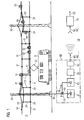
- FIG. 1 shows a monitoring device 10 for monitoring in particular the thermal load of a conductor 2 represented in the form of a catenary of a railway catenary
- FIG. 8 shows a monitoring device 10 for monitoring in particular the thermal load of a conductor 2 shows.
- the overhead line 2 is used to power a Rail traction vehicle 31 via a current collector 32nd
- the overhead line 2 consists essentially of current-carrying Components such as feed line (not shown in Figure 1), carrying cable 22, contact wire 21, and various auxiliary elements such as hangers 23 and mating fasteners 24 for example in the form of clamps or thimbles.
- a plurality of masts 30 are provided for mounting the overhead line 2.
- the contact wire 21 is the operation of the rail traction vehicle 31 required power of, for example, 12 MW and more to the location of the current collector 32 (pantograph) of the railcar 31 transported.
- the contact wire 21 is with a (not shown in Figures 1 and 8) transverse to the contact wire 21 arranged grinding bar of the current collector 32 in Sliding contact.
- the sanding strip is doing with a certain Force, the so-called contact force, against the contact wire 21 pressed. This will be one for the electrical energy supply sufficient electrical contact between contact wire 21 and pantograph 32 formed.
- At least one Catenary 2, which is responsible for a speed of the railcar 31 is designed by over 100 km / h, existing Support cable 22 has a carrying function and also serves in addition for power supply.
- a modern overhead line 2 which allows a very high speed, can for Power supply in addition to the contact wire 21 and the support cable 22nd
- other electrical (part) conductor for example in Form of a so-called reinforcing line, be provided.
- the FBG sensors 41 to 45 and 51 to 53 are in the example of Figure 1 with irregular intervals (optically serial to each other) inscribed in an optical waveguide 40. she are thus integral parts of the same.
- An institution with a plurality, in particular optically parallel to each other Fiber optic cables with integrated FBG sensors is also possible.
- the optical fiber 40 as shown in Figure 1 is a one-piece construction or a Structure of several, at least visually interconnected Subsections are selected.
- the force acting on the contact wire 21 force directions 8 is a coordinate system 80 with a x-, y- and z-axis applied.
- the force component in the z direction can be understood as the contact force.
- the Forces in the Y direction occur as transverse and cutting forces and are, for example, to the partial entrainment of the contact wire 21 in grooves of a defective contact strip.
- Cross and cutting forces also occur due to the zigzag arrangement of the contact wire 21 in the direction of travel on, when driving the rail traction vehicle 31 a transverse movement the contact wire 21 relative to the current collector 32 and entails a frictional force associated with it.
- the Forces in the x-direction are called longitudinal forces by the friction between the contact strip and contact wire 21 at Driving in the direction of travel caused.
- optical sensors 54 to 56 In the form of fiber Bragg grating (FBG) sensors intended.
- FBG fiber Bragg grating
- the distribution shown in Figure 8 this FBG sensors 54 to 56 are only examples. Other Sensor distributions are also possible.
- the single ones Measuring sections along the conductor 2 are each with a Sensor pair 54 to 56 provided in fiber optic strands are inscribed.
- Each sensor of a pair 54 to 56 is assigned to an optical fiber strand.
- the in Figure 8 illustrated optical waveguide 40 is thus as a double strand to understand. There are more at one location as two sensors, each one an optical fiber strand are assigned, conceivable.
- the fiber optic strands can while parts of a single optical waveguide 2 or be each also correspond to an optical waveguide 2. Of the or the optical waveguide 2 may be constructed in one piece or even from several at least visually with each other connected parts.
- Each of the FBG sensors 41 to 45 and 51 to 53 in Figure 1 and 54 to 56 in Fig. 2 has a specific centroid wavelength - the so-called Bragg wavelength - which differs from that the other FBG sensors 41-45 and 51-53 in Figure 1 and 54 to 56 in Figure 2 differs.
- the injected light signal LS a share with the respective center wavelength as a partial-reflection light signal reflected back. The remainder of the light signal
- LS passes through the respective sensor 41 to 45 and 51 to 53 in Figure 1 and 54 to 56 in Figure 2 and applies to the next sensor 41 to 45 and 51 to 53 in FIGS. 1 and 54 to 56 in Figure 2.
- the coupler 62 is then one of the FBG sensors 41 to 45 and 51 to 53 in FIGS. 1 and 54 to 56 in FIG 2 reflected light signal LS 'on, resulting from the partial-reflection light signals of the individual FBG sensors 41 to 45 and 51 to 53 in Figure 1 and 54 to 56 in Figure 2 composed.
- the pending at the coupler 62 reflected light signal LS ' is passed from the coupler 62 to an opto-electrical converter 63.
- the latter includes in particular a spectrally selective Element for selecting the individual partial-reflection light signals, for example in the form of a polychromator and an optionally also multi-part light receiver.
- a spectrally selective Element for selecting the individual partial-reflection light signals, for example in the form of a polychromator and an optionally also multi-part light receiver.
- to Analysis of the light spectrum are grating or diffraction spectrometers conceivable.
- Following the optoelectronic conversion finds in an A / D converter 64 an analog / digital conversion instead of.
- the digitized output signal of the A / D converter 64 is supplied to a digital evaluation unit 65, in the Measured values M1, M2, M3, M4, ...
- the coupler 62 is at one End of the optical waveguide 40 and the optical waveguide 40th the light signal LS coupled by means of the light source 61 and at the other end of the optical waveguide 40 and the optical waveguide 40 detected by an opto-electrical converter 63.
- the light source 61, the coupler 62, the opto-electrical converter 63, the A / D converter 64 and the evaluation unit 65 are in a transmitting / receiving unit 60, wherein the subunit from light source 61 and coupler 62 as means for Feeding the light signal LS into the FBG sensors 41 to 45 and 51 to 53 in Figure 1 and 54 to 56 in Figure 2 and the Subunit of optoelectric transducer 63, A / D converter 64 and evaluation unit 65 as means for determining a measured value M1, M2, M3, M4, ... for the FBG sensors 41 to 45 and 51 to 53 in Figure 1 and 54 to 56 in Figure 2, respectively can be understood.
- these subunits or parts of it are structurally separated, that is, not as a common transmitting / receiving unit 60, be educated.
- a purely analog evaluation for example by means of a hard-wired electronic Circuit possible. Then no A / D converter 64 would be present and the evaluation unit 65 realized analogously.
- the transmitting / receiving unit 60 of each in Figure 1 and FIG 8 is at ground potential, where however, the overhead line 2 on a in the railway energy supply usual potential, in particular from 15 to 25 kV, lies.
- the bridging of this potential difference takes place by means of the optical waveguide 40 or the optical waveguide 40, via the / the also fed light signal LS and the reflected light signal LS 'are transmitted.
- the optical fiber (s) 40 consists of a dielectric material, such as glass or plastic. This is no separate measures for electrical insulation required.
- the generated in the respective transmitting / receiving unit 60 Measured values M1, M2, M3, M4,... In FIG. 1 and FIG by means of a radio transmission to a data acquisition unit 90 transmitted.
- the data transfer can basically also wired electrical or optical'er réelle.
- the transmitting / receiving unit 60 and the data acquisition unit 90 also formed as a common entity be.
- control unit 70 in Figure 1 is a protection concept deposited for the overhead line 2.
- a protective measure for the Catenary 2 is to be initiated.
- the Current flow in the overhead line 2 can be reduced to the overhead line 2 in case of too high thermal or mechanical To protect stress from destruction. in the In extreme cases, the overhead line 2 can also be switched off become.
- These measures are taken over by the control unit 70 generated control signal CS initiated.
- the determined overstress causes the control signal CS in a switching unit, not shown in Figure 1 For example, a reduction of the current flow.
- FIG. 8 shows a further transceiver unit 95, with the data D31 to identify the in the "Quality Gate" received 11 incoming railcars become.
- the transmitting / receiving unit 33 may for example be designed such that their operating energy from one of the transmitting / receiving unit 95 radiated electromagnetic field 96 refers. In principle, it is also conceivable to transfer the data to make optical ways.
- the obtained railway traction vehicle data are passed on by the transmitting / receiving unit 95 transmitted to the data acquisition unit 90 and together with the corresponding, transmitted by the transmitting / receiving unit 60 Measured values M3, M4, ... stored.
- the one for the Catenary 2 responsible infrastructure operators thus has also at a later date the opportunity to be recorded and assigned to the individual rail traction vehicles To access measured values.
- the from the transmitting / receiving unit 60 to the data acquisition unit 90 transmitted measured values M3, M4, ... are above in addition by means of a radio transmission to a control unit 70 transmitted.
- the data transfer can basically also conducted by wire electrical or optical.
- the transmitting / receiving units 60 and 95, the Data acquisition unit 90 and the control unit 70 also as be formed common entity.
- control unit 70 is a protection concept for the overhead line 2 deposited. Depending on the size of the measured values M3, M4, ... for the actual mechanical load is decided in the control unit 70, if a Protective measure for the overhead line 2 is to be initiated. Especially can the current collector from the 32 on the overhead line. 2 acting force is reduced or increased to the catenary 2 in case of excessive mechanical load before one To protect destruction. These measures will be over initiated by the control unit 70 control signal CS initiated for example by radio transmission to the railcar 31 is sent. In addition, the railcar driver can the his railcar 31 assigned measured data M3, M4, ... transmitted by radio transmission so that he has the opportunity, if necessary rules intervene.
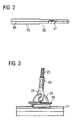
- Figures 2 to 7 are ways to attach the FBG sensors 41 to 45 and 51 to 53 on or in the components the overhead line 2 shown.
- the FBG sensor 41 is shown in FIG. 2 as executed in a housing 55 embedded sensor 59.
- the Optical fiber 40 is located with the integrated FBG sensor 41 itself in a for example round housing, whereby the optical fiber 40 and the FBG sensor 41 to rough Environmental conditions is protected and also a mechanical Decoupling of the FBG sensor 41 from the component to be monitored Catenary 2, on or in the embedded one Sensor 59 is to be attached to ensure.
- a mechanical decoupling is advantageous. In difference this would be in an FBG strain sensor 51 to 53 just one non-positive coupling with the component to be monitored the overhead line 2 sought (positive connection).
- a sensor network as shown in Figure 1 and Figure 8,
- the sensor 59 may be last Sensor used in the light path.
- the sensor 59 in particular in connection with a coupler 62 comparable Element also at any point in the sensor network of Figure 1 and Figure 8 are used.
- a transmissive embodiment possible.
- Then 55 is on the right edge of the housing of the sump or reflector close an outlet for the optical waveguide 40 is provided.
- FIG. 3 is shown schematically how two embedded Sensors 59 according to FIG. 2 on connecting elements 24 and 25 the overhead line 2 are attached.
- the element 24 as a plug-in clamp for attaching the trailer 23rd executed on the contact wire 21.
- the element 25, however, is a Kausche with notch connector.
- the FBG sensors 41 to 45 and 51 to 53 also on other connecting elements attach the overhead line 2.
- Examples of other such attaching an FBG sensor 41 to 45 and 51 to 53 suitable fasteners For example, a tooth clamp, a power terminal for the Support cable 22 or the contact wire 21, a screw-clamp for attachment of the trailer 23 on the support cable 22 or on the contact wire 21, a trolley jumper or a bridge clamp.
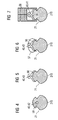
- Figures 4 to 7 are ways to arrange the Optical waveguide 40 including the example selected FBG sensors 41 to 43 shown in or on the contact wire 21.
- the attachment is in each case preferably on or in a region of the contact wire 21, that of a contact side 210 is opposite.
- the contact side 210 is used for sliding contact of the contact wire 21 with the current collector 32nd für the attachment in one of the contact side 210 opposite Range is the mechanical load of the optical fiber 40 kept as low as possible. simultaneously the FBG sensors 41 to 43 are still very close at the actually interesting measuring point, namely at the thermally highly charged contact side 210.
- This accommodation is very space saving.
- the outer dimensions of the overhead line 2 are at this Type of attachment of the optical waveguide 40 and the sensor 42 virtually unchanged.
- the optical fiber 40 with the FBG sensors 43 and 41 is the optical fiber 40 with the FBG sensors 43 and 41, however, not in the contact wire 21 itself, but in an additional provided receiving element 56, for example be designed as an adapter made of copper or a plastic can, arranged.
- the receiving element 56 then contains a Hollow channel in which the optical fiber 40 including FBG sensors 43 and 41 is relocated.
- the receiving element 56 but also positively around the optical fiber 40 and the FBG sensors 43 and 41 may be arranged.
- One such positive fit results in particular when used a customary in plastics processing manufacturing process, for example, a spraying and / or casting process.
- the receiving element 56 is in the embodiment of FIG 5 glued or soldered to the contact wire 21 and in the Embodiments of Figures 6 and 7 on the contact wire 21st clamped.
- the clamp connection is made as shown of Figure 6 by means of an additionally provided clamping device 57, whereas in the embodiment of FIG the clamp connection by means of an already existing clamping device 58 is realized.
- the to accommodate the Receiving member 56 certain cavity within the clamping device 58 can - as in the example of Figure 7 - anyway to be available. But he can also by targeted change the constructive elements of the clamping device 58th have been introduced. Furthermore, in the example of FIG 6 instead of the clamping device 57, a screw connection be provided.
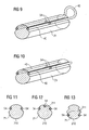
- FIG. 9 shows an exemplary embodiment with an optical waveguide 40, while in Figure 10, an FBG sensor each in a Optical waveguide 40 is arranged.
- the FBG sensor pairs 40 parallel to each other on the same Length of the conductor to be examined 2, as in the two figures represented, arranged.
- FIGS. 11 to 13 show, on the basis of contact wire cross-sections, at which points FBG sensors 54 to 56 are preferably arranged become.
- FIG. 12 shows an embodiment, in which two FBG sensors 54 laterally in each case a groove 211 are arranged.
- FIG 14 is a contact wire section 21 with a contact wire 21 mounted optical fiber 40 shown.
- the optical waveguide 40 with a "Single-ended" sensor 47 executed. It can be seen, in that the optical waveguide 40 is connected by means of connections 81, in particular clamping and / or screw, on the contact wire 21 is guided along and the end of the optical waveguide 40 with the optical sensor 47 of another Clamping and / or screw 82 or 83 on the contact wire 21st is attached.
- connections 81 in particular clamping and / or screw
- Figure 15 shows a clamping connection 81, which by a on a Biasing means 84, for example a screw with nut, introduced bias on the contact wire 21 is fixed.
- a Biasing means 84 for example a screw with nut
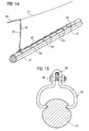
- Figure 16 shows one of a flange 88 and a bow-shaped Body 87 existing two-piece clamp connection 82, the also by a biasing means 84, for example a screw, introduced bias on the contact wire 21 is fixed.
- the clamping connection 82 is designed such that they form-fit on the top of the contact wire 21 can be arranged.
- the optical waveguide 40th with the optical sensor 46 has thereby also through the positive locking, in particular in a bore of Clamping connection 82, force and / or heat-sealing contact with the contact wire 21.
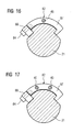
- Figure 17 further shows a corresponding embodiment, with the two optical fibers 40 with optical sensor 46 recorded can be.
- Conceivable are also the embodiments can accommodate more than two optical fibers 40.
- the maximal Number of the receivable optical fiber 40 depends essentially the dimensions of the corresponding clamping connection 82 and the diameters of the optical waveguides 40th from.
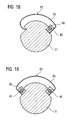
- an exemplary embodiment 83 is one of each Clamping connection shown without additional biasing means 84, such as screws, manages.
- Both shown clamping connections 83 consist of a or two receiving elements 86, wherein each receiving element 86 is in each case provided in particular with a bore and in the form-fitting and thus power and / or heat-dissipating in each case an optical waveguide 40 are arranged can.
- the two clamp connections 83 in each case an elastic strap 85, in particular a leaf spring. With the help of the leaf spring 85, a bias voltage such be constructed that the respective clamping connection 83 without additional biasing means 84 are fixed to the contact wire can.
- FIGS. 16 and 18 are designed in this way that they form-fit contact with the already design-related existing recess of the contact wire 21st to have. This ultimately provides a force and / or heat-conclusive Contact of the optical sensor 46 and the optical Sensors 46 with the contact wire 21.
- the assembly of the clamping connections 83 is very simple, since they only on the contact wire 21 "must be clipped".
- the embodiments shown in FIGS. 16 and 18 are preferably for temperature and strain monitoring while those shown in FIGS. 17 and 19 are used Embodiments with their two optical Sensors 46 preferably for determining the outside of the contact wire
- FIGS. 1 and 8 can be easily combined. So can together with the supervision of the mechanical load always the supervision the thermal load of the monitored control components be performed. This underlines particularly the advantageous flexibility and compatibility of both in the figures 1 and 8 devices shown.
Abstract
Description
Optisches Verfahren und optische Einrichtung zur Überwachung eines elektrischen Leiters. Insbesondere handelt es sich bei dem Leiter um die Oberleitung oder einen Teil der Oberleitung, die zur elektrischen Energieversorgung eines Schienentriebfahrzeuges bestimmt ist.Optical method and optical device for monitoring an electrical conductor. In particular, it is with the conductor around the overhead line or part of the overhead line, for the electrical power supply of a railcar is determined.
Ein Schienentriebfahrzeug wird über einen elektrischen (Strom-)Leiter in Form einer Oberleitung mit elektrischer Energie versorgt. Die Energie gelangt mittels eines mit der Oberleitung in mechanischem Schleifkontakt stehenden Stromabnehmers von der Oberleitung über eine Schleifleiste zum Schienentriebfahrzeug. Um eine hohe Sicherheit, Verfügbarkeit und Zuverlässigkeit zu gewährleisten, sind außer der Oberleitung praktisch alle Betriebsmittel der Bahnenergieübertragung und -verteilung redundant ausgeführt. Bei der Oberleitung erfolgt dies aus technischen und wirtschaftlichen Gründen nicht. Dennoch zieht ein Ausfall der Oberleitung zumindest auf dem vom Oberleitungs-Ausfall betroffenen Streckenabschnitt meistens auch einen Ausfall der kompletten Bahn-Energieversorgung nach sich. Mit jedem derartigen Ausfall sind hohe Kosten verbunden.A railcar is powered by an electric (Electric) conductor in the form of a catenary with electrical Energy supplied. The energy passes through a with the Catenary with current collector in mechanical sliding contact from the overhead contact line via a contact strip for Rail train. For a high security, availability and to ensure reliability are beyond the overhead line practically all equipment of the railway energy transmission and distributed redundant. In the overhead line is done this for technical and economic reasons Not. Nevertheless, a failure of the overhead line pulls at least on the section affected by the trolley failure usually also a failure of the entire rail energy supply after himself. With every such failure are associated with high costs.
Eine Oberleitung besteht im Wesentlichen aus etwa zwanzig, in Reihe geschalteten Teilelementen, die in Form von Maschen angeordnet sind und das sogenannte Kettenwerk bilden. Fällt ein Teilelement aus, so fällt auch die Oberleitung insgesamt aus.A catenary essentially consists of about twenty, in Row of connected sub-elements arranged in the form of meshes are and form the so-called catenary. Come in mind Partial element off, so the overhead line also fails altogether.
Das Ausfallverhalten wird durch zahlreiche Einflussgrößen bestimmt, wobei eine thermische Überlastung einzelner Komponenten der Oberleitung als Hauptursache für die Nichtverfügbarkeit anzusehen ist. The failure behavior is determined by numerous influencing variables, being a thermal overload of individual components the overhead line as the main cause of unavailability is to be considered.
Eine zu hohe thermische Beanspruchung der Oberleitung kann beispielsweise eine unzulässige Längsdehnung des Kettenwerks und damit eine Entgleisung des Stromabnehmers zur Folge haben. Dann ist eine kostenträchtige Beschädigung der Oberleitung und/oder des Stromabnehmers sehr wahrscheinlich. Außerdem kann eine thermische Überlastung zu einer Beeinträchtigung der mechanischen Festigkeit, insbesondere zu einer Entfestigung des Fahrdrahts der Oberleitung führen.Too high thermal stress on the overhead line can For example, an inadmissible longitudinal expansion of the catenary resulting in a derailment of the pantograph. Then there is a costly damage to the overhead line and / or the pantograph very likely. Furthermore Thermal overload can be detrimental the mechanical strength, in particular to a softening lead of the contact wire of the overhead line.
Zu thermischer Überlastung kann es beispielsweise aufgrund einer hohen Außentemperatur, eines hohen Übergangswiderstands an einem sich lockernden Verbindungselement sowie eines zu hohen Stromflusses kommen. Letzteres ist insbesondere angesichts des steigenden Leistungsbedarfs zukünftiger Hochleistungs-Schienentriebfahrzeuge zu beachten. Dieser Bedarf ergibt sich aus dem wachsenden Komfortangebot innerhalb der Fahrzeuge (Vollklimatisierung, TV, Multimedia, usw.), den hohen Stromspitzen durch das Anfahren, den in zunehmendem Maße eingesetzten elektrischen Rückspeisebremsen und der steigenden Zuggeschwindigkeit von 300 km/h und mehr. Daraus resultiert der Wunsch nach einer möglichst hohen Ausnutzung der Oberleitung.For example, due to thermal overload a high outside temperature, a high contact resistance on a loosening connecting element and one to high current flow come. The latter is especially given the increasing power requirements of future high-performance rail traction vehicles to be observed. This need arises from the growing comfort offer within the Vehicles (air conditioning, TV, multimedia, etc.), the high Power spikes by starting, the increasingly used electric regenerative brakes and the rising Train speed of 300 km / h and more. This results the desire for the highest possible utilization of the Catenary.
Um dann aber dennoch eine sichere Energieversorgung zu gewährleisten, ist eine genau arbeitende Überlastschutzeinrichtung erforderlich. Sowohl ein unzulässig hoher Betriebsstrom als auch ein Kurzschlussstrom (bis zu 45 kA) werden von einer solchen Schutzeinrichtung erkannt und abgeschaltet. Dadurch wird die Oberleitung vor Abbrand geschützt und die Zahl der Betriebsunterbrechungen reduziert. Diese Schutz-Funktion bietet eine mehrstufige digitale Distanzschutzeinrichtung, wie sie zum Beispiel in "Digitalschutz für Bahnenergienetze", H.-J. Braun, et al., Elektrische Bahnen 97, 1999, Heft 1/2, S. 32-39, beschrieben ist. Messgrößen sind hierbei in erster Linie die elektrische Spannung und der elektrische Strom. However, in order to ensure a secure power supply, a well-functioning overload protection device is required. Both an impermissibly high operating current and a short-circuit current (up to 45 kA) are detected by such a protective device and switched off. This protects the overhead contact line from burning and reduces the number of business interruptions. This protection function provides a multi-level digital distance protection device, as described, for example, in "Digital Protection for Rail Freight Networks", H.-J. Braun, et al., Electric Railways 97, 1999, Issue 1/2, p. 32-39 . Measurands are primarily the electrical voltage and the electric current.
Um bestehende und neue Bahntrassen für die zukünftigen Anforderungen und gegen zu hohe Ausfallraten zu rüsten, kann zusätzlich ein Monitoring der thermischen Belastung der Oberleitung nützlich sein. Bei einer solchen Einrichtung wird derzeit die primär interessierende thermische Belastung einzelner Komponenten der Oberleitung allerdings nur indirekt anhand verschiedener Hilfs-Messgrößen ermittelt. Wie aus dem Gerätehandbuch "Siemens Digitaler Oberleitungsschutz 7SA517 V3. 4 ", Siemens AG, Transportation Systems, 08/2001, Bestell Nr. E50410-A0011-U501-A2-0091, Seiten 3-12 bis 3-14 hervorgeht, basiert dieser thermische Überlastschutz auf einem thermischen Modell mit Gedächtnisfunktion, das unter Zugrundelegung des Stromeffektivwertes und der Außentemperatur die Temperatur des Fahrdraht der Oberleitung berechnet und diese mit einem einstellbaren zulässigen Maximalwert vergleicht. Die Verwendung des thermischen Modells kann jedoch zu einem ungenauen Resultat führen. Die rechnerisch ermittelte und die tatsächlich vorliegende Temperatur der Oberleitungskomponente können voneinander abweichen mit der Folge, dass eine abgeleitete Schutzmaßnahme nicht optimal auf die tatsächlichen Gegebenheiten abgestimmt ist.In order to equip existing and new railway lines for the future requirements and against too high failure rates, monitoring of the thermal load of the overhead line can additionally be useful. In such a device, however, the thermal load of individual components of the overhead line of primary interest is currently determined only indirectly by means of various auxiliary measured variables. As can be seen from the manual "Siemens Digital Catenary Protection 7SA517 V3.4", Siemens AG, Transportation Systems, 08/2001, Order No. E50410-A0011-U501-A2-0091, pages 3-12 to 3-14 , this thermal is based Overload protection on a thermal model with memory function that calculates the temperature of the contact wire of the overhead contact line based on the effective current value and the outside temperature and compares this with an adjustable permissible maximum value. However, the use of the thermal model can lead to an inaccurate result. The computationally determined and actually present temperature of the overhead line component may differ, with the result that a derived protective measure is not optimally adapted to the actual circumstances.
Ein ähnliches Verfahren zur Zustandsüberwachung einer Hochspannungs-Freileitung, bei dem ein Approximationsmodell zur indirekten Ermittlung der Leitertemperatur zum Einsatz kommt, wird mit der DE 19718186 C1 offenbart.A similar method for condition monitoring of a high-voltage overhead line, in which an approximation model for the indirect determination of the conductor temperature is used, is disclosed in DE 19718186 C1 .
In den Schutzrechten US 4635055 A1, US 4894785 A1, US 4904996 A1, US 5006846 A1 und US 5341088 A1 werden jeweils elektrische Sensoren beschrieben, die zur Montage an einer Hochspannungs-Freileitung bestimmt sind und die aus dem zu überwachenden Leiter mit elektrischer Energie gespeist werden. Erfasst werden auf Hochspannungspotential vielfältige Messgrößen wie Sonneneinstrahlung, Leiterstrom, Leiterspannung, Windgeschwindigkeit und -richtung, relative Feuchte, Außentemperatur, und auch die Temperatur und Dehnung des Hochspannungs-Leiters. Die erfassten Signale werden per Funkverbindung oder bei der in der US 5006846 A1 gezeigten Einrichtung per optischer Verbindung an eine Bodenstation übertragen. Diese Sensoren haben alle eine den zu überwachenden Leiter komplett umschließende Konstruktion, die zur induktiven Auskopplung der zum Betrieb der elektrischen Sensoren benötigten Energie aus dem zu überwachenden Leiter insbesondere auch einen magnetischen Transformator, beispielsweise in Form eines magnetischen Ringkern-Wandlers, beinhaltet. Ein Einsatz in der Bahn-Energieversorgung ist somit wegen des dort üblichen Schleifkontakts zwischen dem Stromabnehmer und dem Fahrdraht technisch nur schwer oder gar nicht möglich.The protective rights US 4635055 A1, US 4894785 A1, US 4904996 A1, US 5006846 A1 and US 5341088 A1 each describe electrical sensors which are intended for mounting on a high-voltage overhead line and which are fed with electrical energy from the conductor to be monitored , High-voltage potentials include various variables such as solar radiation, phase current, conductor voltage, wind speed and direction, relative humidity, outside temperature, as well as the temperature and strain of the high-voltage conductor. The detected signals are transmitted via radio link or in the device shown in US 5006846 A1 by optical link to a ground station. These sensors all have a construction completely enclosing the conductor to be monitored, which in particular also includes a magnetic transformer, for example in the form of a magnetic toroidal core transformer, for inductive decoupling of the energy required to operate the electrical sensors from the conductor to be monitored. An insert in the rail energy supply is thus technically difficult or impossible because of the usual there sliding contact between the pantograph and the contact wire.
Mit dem Aufsatz "Measurements of overhead transmission line loads with Bragg gratings", L.Bjerkam, Conference Proceedings, SPIE Vol. 3746, S.514-517, OFS-13, Kyongju, Korea, 12.-16.04.1999, wird eine Dehnungsmessung an einer Hochspannungsfreileitung mittels Faser-Bragg-Gitter-Sensoren (FBG)-Sensoren offenbart. Zur Messung von dynamischen Dehnungsamplituden des stromführenden Leiters sind an einem 160 m langen Teilstück einer 60 kV-Freileitung insgesamt drei FBG-Sensoren angeordnet. Einer davon dient zur Erfassung einer Temperaturreferenz. Die beiden FBG-Sensoren zur Dehnungsmessung sind direkt auf den zu überwachenden Leiter geklebt. Von einem eingespeisten Lichtsignal wird ein Anteil mit der Schwerpunktswellenlänge des jeweiligen FBG-Sensors zu einer Auswerteeinheit zurückreflektiert. Die Schwerpunktswellenlänge ändert sich mit der am Messort herrschenden Dehnung, so dass ihre Veränderung als Messgröße für die Dehnung verwendet werden kann. Ein Verfahren oder eine Einrichtung zur Überwachung der thermischen Belastung, insbesondere einer Bahn-Oberleitung, wird in dem Aufsatz jedoch nicht erwähnt.The article "Measurements of overhead transmission line loads with Bragg gratings", L.Bjerkam, Conference Proceedings, SPIE Vol. 3746, p.514-517, OFS-13, Kyongju, Korea, 12.-16.04.1999, becomes a Strain measurement on a power transmission line using fiber Bragg grating sensors (FBG) sensors disclosed. To measure dynamic strain amplitudes of the current-carrying conductor, a total of three FBG sensors are arranged on a 160 m long section of a 60 kV overhead line. One of them serves to record a temperature reference. The two FBG sensors for strain measurement are glued directly onto the conductor to be monitored. From an input light signal, a component with the center-of-mass wavelength of the respective FBG sensor is reflected back to an evaluation unit. The centroid wavelength changes with the strain at the measurement site, so that its change can be used as a measure of strain. However, a method or device for monitoring the thermal load, in particular a railway catenary, is not mentioned in the article.
Ein signifikanter Anteil der Ausfallursachen von Oberleitungen kann auch auf eine fehlerhafte Interaktion zwischen Schienentriebfahrzeug und der Oberleitung zurückgeführt werden. A significant proportion of failure causes of overhead lines may also be due to a faulty interaction between Rail traction vehicle and the overhead line are returned.
So kann die Presskraft des Stromabnehmers an den sogenannten Fahrdraht der Oberleitung unangemessen sein. Bei überhöhten Anpresskräften, die auch Kontaktkräfte genannt werden, wird der Fahrdraht und auch die Schleifleiste einem übermäßigen Verschleiß ausgesetzt. Bei zu niedrigen Kontaktkräften kann es im Fahrbetrieb auch zu Kontaktverlusten kommen, die Lichtbögen zwischen Fahrdraht und Schleifleiste hervorrufen können. Durch die sehr hohen Temperaturen im Lichtbogen können Schäden durch Materialabtrag am Fahrdraht und am Stromabnehmer entstehen. Weist die Schleifleiste beispielsweise Riefen auf, kann im Fahrbetrieb der Fahrdraht kurzzeitig in diese Riefen mitgeführt werden. Dies kann zu unspezifischen Auslenkungen des gesamten Kettenwerks führen. Im schlimmsten Fall kann es dabei zu einer "Entgleisung" des Stromabnehmers kommen.Thus, the pressing force of the pantograph on the so-called Contact wire of the overhead line to be inappropriate. In case of excessive Pressing forces, which are also called contact forces, will the contact wire and also the contact strip an excessive Exposed to wear. At too low contact forces can There are also contact losses during driving, the electric arcs between contact wire and contact strip can cause. Due to the very high temperatures in the arc can Damage due to material removal on the contact wire and the pantograph arise. For example, if the sanding strip has grooves can, during driving, the contact wire briefly in this Ridges are carried. This can lead to unspecific deflections of the entire chainwork. In the worst case This can lead to a "derailment" of the pantograph.
Für Infrastrukturbetreiber, die für die Oberleitung verantwortlich sind, ist es daher von großem Interesse, mit einem so genannten "Quality Gate" die Interaktion zwischen der Oberleitung und dem entsprechenden Schienentriebfahrzeug erfassen zu können, um gegebenenfalls regulierend einzugreifen und auch beispielsweise die Schuldfrage bei Vorfällen eindeutig klären zu können. In "Stromabnehmerdiagnose im laufenden Betrieb durch stationäre Anhubmessung", H. Möller, et al., Elektrische Bahnen 100, 2002, Heft 6, S. 198-203 ist ein solches "Quality Gate" beschrieben. Die Veröffentlichung legt dar, wie mit der Ermittlung des Fahrdrahtanhubs auf die Kontaktkraft zwischen Stromabnehmer und Fahrdraht geschlossen wird, um defekte oder falsch eingestellte Stromabnehmer zu erkennen. Dabei wird der Anhub mit einem Seilzugpotentiometer als mechanischem Wegsensor gemessen. Das elektrische Signal des Seilzugpotentiometers wird dann zur Weiterverarbeitung über ein Kabel und einen Trennverstärker einem Messverstärker zugeführt.For infrastructure managers who are responsible for the overhead contact line, it is therefore of great interest to be able to record the interaction between the overhead contact line and the corresponding railcar with a so-called "quality gate" in order to intervene, if necessary, and for example the question of guilt in incidents to clarify. In "Current collector diagnosis during operation by stationary rise measurement", H. Möller, et al., Electric Railways 100, 2002, No. 6, pp. 198-203 such a "Quality Gate" is described. The publication explains how to determine the contact wire force between the pantograph and the contact wire by detecting the contact wire lift in order to detect defective or incorrectly adjusted pantographs. The lift is measured with a pull-cord potentiometer as a mechanical displacement sensor. The electrical signal of the pull-cord potentiometer is then fed to a measuring amplifier for further processing via a cable and a buffer amplifier.
Der Erfindung liegt nun die Aufgabe zugrunde, ein Verfahren und eine Einrichtung anzugeben, die verglichen mit dem Stand der Technik eine verbesserte Überwachung eines elektrischen Leiters im Hinblick auf thermische und/oder mechanische Belastungen ermöglicht. Drüber hinaus wird mit der Erfindung eine detailliertere Ermittlung der auf einen elektrischen Leiter wirkende mechanische Belastung ermöglicht, die darüber hinaus bei einer Anwendung über längere Streckenabschnitte kostengünstiger anzuwenden sind.The invention is based on the object, a method and to provide a facility that compared to the state the technique of improved monitoring of an electrical Ladder with regard to thermal and / or mechanical loads allows. In addition, with the invention a more detailed determination of an electrical Ladder-acting mechanical load allows the above in addition to an application over longer stretches apply more cheaply.
Zur Lösung der das Verfahren betreffenden Aufgabe wird ein Verfahren entsprechend den Merkmalen des unabhängigen Patentanspruchs 1 angegeben.To solve the problem relating to the method is a Method according to the features of the independent claim 1 indicated.
Bei dem erfindungsgemäßen Verfahren handelt es sich um ein optisches Verfahren zur Überwachung eines elektrischen Leiters, bei dem
- mindestens ein optischer Sensor an oder in einer'Komponente des Leiters angeordnet wird,
- ein in den optischen Sensor eingespeistes Lichtsignal aufgrund
einer physikalischen Größe am Ort des optischen Sensors
verändert wird
und - aus der durch die physikalische Größe bedingte Veränderung des Lichtsignals ein Messwert für die physikalische Größe ermittelt wird.
- at least one optical sensor is arranged on or in a component of the conductor,
- a light signal fed to the optical sensor is changed due to a physical quantity at the location of the optical sensor
and - a measured value for the physical quantity is determined from the change in the light signal caused by the physical quantity.
Zur Lösung der die Einrichtung betreffenden Aufgabe wird eine Einrichtung entsprechend den Merkmalen des unabhängigen Patentanspruchs 18 angegeben.To solve the task concerning the device is a Device according to the features of the independent claim 18 indicated.
Bei der erfindungsgemäßen Einrichtung handelt es sich um eine optische Einrichtung zur Überwachung eines elektrischen Leiters umfassend
- mindestens einen an oder in einer Komponente des Leiters angeordneten optischen Sensor,
- Einspeisemittel zur Einspeisung eines Lichtsignals in den
optischen Sensor, wobei
eine zu erfassende physikalische Größe eine Änderung des Lichtsignals bewirkt
und - Auswertemittel zur Bestimmung eines Messwertes für die physikalische Größe aus der durch die physikalische Größe bedingten Änderung des Lichtsignals.
- at least one optical sensor arranged on or in a component of the conductor,
- Feeding means for feeding a light signal into the optical sensor, wherein
a physical quantity to be detected causes a change in the light signal
and - Evaluation means for determining a measured value for the physical quantity from the change in the light signal caused by the physical quantity.
Die Erfindung beruht dabei auf der Erkenntnis, dass durch die Verwendung eines optischen Sensors zur Erfassung einer physikalischen Größe, mit der beispielweise eine thermische und/oder mechanische Belastung der Leiterkomponente einher geht, die tatsächliche physikalische Größe wesentlich genauer bestimmt werden kann, als bei den derzeit aus dem Stand der Technik bekannten Überwachungs- bzw. Schutzeinrichtung für Oberleitungen.The invention is based on the knowledge that through the Use of an optical sensor for detecting a physical Size, with the example of a thermal and / or mechanical stress on the conductor component goes hand in hand, the actual physical size is determined much more accurately can be, as at the moment from the state of the Technik known monitoring or protective device for Overhead lines.
Als zu überwachende Komponenten des Leiters, der insbesondere auch als Leitersystem, wie bei einer Bahn-Oberleitung, ausgebildet sein kann, kommen beispielsweise ein metallischer Draht oder verseilter Drahtstrang, ein Verbindungselement wie eine Klemme oder auch ein massives Gussbauteil in Betracht. Aufgrund seiner geringen Baugröße lässt sich ein optischer Sensor leicht an oder in einer solchen Komponente anbringen. Hierfür ist entweder gar keine oder nur eine sehr geringfügige konstruktive Anpassung der Komponente, beispielsweise in Form einer Nut, eines Bohrlochs oder eines Adapterstücks, erforderlich.As components of the conductor to be monitored, in particular Also designed as a ladder system, as in a railway overhead line can be, come, for example, a metallic Wire or stranded wire strand, a fastener like a clamp or a solid cast component into consideration. Due to its small size can be an optical Lightly attach the sensor to or in such a component. For this is either no or only a very small constructive adaptation of the component, for example in Shape of a groove, a borehole or an adapter piece required.
Ein Vorteil eines optischen Sensors gegenüber einem konventionellen elektrischen Sensor ist seine intrinsische Potentialtrennung. Die optische Abfrage kann mittels einer optischen Freistrahlanordnung oder auch mittels mindestens einer dielektrischen Zuleitung, beispielsweise in Gestalt eines Lichtwellenleiters aus Glas oder aus Kunststoff, erfolgen. Damit ist es möglich, ohne gesondertem oder mit verhältnismäßig geringem Isolationsaufwand eine solche dielektrische Zuoder Ableitung zu installieren. Aufgrund der hohen Verfügbarkeit von Standard-Glasfaserkomponenten, die sich besonders gut für die dielektrische Zu-/Ableitung einsetzen lassen, resultiert neben einem technischen auch ein großer wirtschaftlicher Vorteil.An advantage of an optical sensor over a conventional one electrical sensor is its intrinsic potential separation. The optical query can be performed by means of an optical Free jet arrangement or by at least one dielectric feed line, for example in the form of a Fiber optic of glass or plastic, made. Thus it is possible, without separate or with relative low isolation costs such a dielectric Zuoder Drain to install. Due to the high availability of standard fiberglass components that are special good for the dielectric supply / discharge, results in addition to a technical and a great economic Advantage.
Vorteilhafte Ausgestaltungen des Verfahrens und der Einrichtung gemäß der Erfindung ergeben sich aus den von Anspruch 1 bzw. 18 abhängigen Ansprüchen.Advantageous embodiments of the method and the device According to the invention, it is apparent from those of claim 1 or 18 dependent claims.
Besonders vorteilhaft ist, wenn die physikalische Größe die Temperatur der Komponente des Leiters ist. Die direkte Temperaturerfassung erübrigt das in einer gängigen digitalen Oberleitungsschutzeinrichtung zugrunde gelegte numerische Modell zur Approximation der Leitertemperatur. Damit treten auch die durch das Approximationsmodell bedingten Unsicherheiten und/oder Ungenauigkeiten nicht mehr auf.It is particularly advantageous if the physical size of the Temperature of the component of the conductor is. The direct temperature detection this is unnecessary in a conventional digital trolley line protection device underlying numerical model for approximation of the conductor temperature. This also occurs the inaccuracies caused by the approximation model and / or Inaccuracies no longer up.
Fehlerursachen sind beim Approximationsmodell beispielsweise die Nichtberücksichtigung von Wetterfaktoren wie Windgeschwindigkeit, Windtemperatur, Sonneneinstrahlung, Schattenwurf, relative Luftfeuchte, Niederschlag (Regen, Schnee) und auch die Nichtberücksichtigung topographischer Besonderheiten wie die Höhendifferenz zwischen dem Ort, an dem der elektrische Außentemperatur-Messfühler angebracht ist und dem Ort, an dem die Leitertemperatur eigentlich ermittelt werden soll. Diese Fehlerursachen spielen bei einer direkten Temperaturmessung mittels eines optischen Sensors keine Rolle mehr.Causes of errors are in the approximation model, for example the disregard of weather factors such as wind speed, Wind temperature, sunlight, shadow, relative humidity, precipitation (rain, snow) and also the disregard of topographical features like the height difference between the place where the electric Outside temperature sensor is attached and the place where the conductor temperature should actually be determined. These causes of error play a direct temperature measurement by means of an optical sensor no longer matter.
Wenn der Leiter, wie beispielsweise bei einer Bahn-Oberleitung, als Leitersystem mit mehreren parallelen und/oder verzweigten Teilstrompfaden ausgebildet ist, berücksichtigt das Approximationsmodell die Gesamtstrommenge, nicht jedoch die Teilströme in den einzelnen Teilstrompfaden, so dass eine zunächst nur lokale thermische Überlastung in einem dieser Teilstrompfade auch unerkannt bleiben kann. Durch gezieltes Anbringen eines optischen Temperatur-Sensors an einer als diesbezüglich kritisch bekannten Messstelle, beispielsweise an einer stromführenden Klemmstelle mit erhöhten ohmschen Widerstandsverlusten (Erwärmung), lässt sich auch diese Fehlerquelle des Approximationsmodells wirksam beseitigen.If the ladder, such as a railway catenary, as ladder system with several parallel and / or branched Teilstrompfaden is formed, takes into account the Approximation model the total amount of electricity, but not the Partial flows in the individual Teilstrompfaden, so a first only local thermal overload in one of these Partial current paths can also remain undetected. Through targeted Attaching an optical temperature sensor to one as in this regard critically known measuring point, for example at a live terminal point with increased ohmic resistance losses (Warming), can also be this source of error effectively eliminate the approximation model.
Durch die Einbindung der tatsächlich ermittelten Temperatur in ein entsprechendes Schutzkonzept kann also ein verbesserter Schutz vor thermischer Überlastung des Leiters erzielt werden. Anhand der direkt gemessenen Temperatur-Information kann eine zustandsorientierte Reduzierung des im Leiter fließenden Stroms, oder auch eine zustandsorientierte Wartung erfolgen.By integrating the actually determined temperature in a corresponding protection concept can thus be an improved Protection against thermal overload of the conductor achieved become. Based on the directly measured temperature information can be a condition-based reduction of the flow in the leader Electricity, or even a condition-based maintenance.
Die aufgrund des unsichereren Approximationsmodells bislang vorgesehenen Sicherheitsreserven im Schutzkonzept können bei Ermittlung der tatsächlichen thermischen Belastung außerdem zumindest deutlich reduziert werden, wodurch der Leiter bei einem höheren Strom betrieben werden kann. Gleichzeitig wird eine Schutzmaßnahme, beispielsweise eine Reduzierung des Stromflusses oder eine komplette Freischaltung, nur bei einer tatsächlich vorhandenen thermischen Überlastung, also insbesondere bei Überschreiten eines thermischen Grenzwerts, vorgenommen. Es ist auch ein mehrstufiges oder gestaffeltes Schutzkonzept mit mehreren solcher Grenzwerte möglich, bei dem die eingeleiteten Schutzmaßnahmen dann je nach überschrittenem Grenzwert unterschiedlich ausfallen. Insgesamt wird die Gefahr einer kostenträchtigen irrtümlichen Freischaltung des Leiters aufgrund der Einbeziehung der tatsächlichen thermischen Belastung also erheblich reduziert.The so far due to the less certain approximation model provided safety reserves in the protection concept can at Determining the actual thermal load as well be reduced at least significantly, causing the conductor at can be operated at a higher current. At the same time a protective measure, for example a reduction of the Current flow or a complete activation, only one actually existing thermal overload, ie in particular when a thermal limit is exceeded. It's also a multi-level or staggered one Protection concept with several such limits possible, at which the protective measures taken then depending on exceeded Limit value vary. All in all the risk of a costly erroneous activation of the director due to the inclusion of the actual Thermal load significantly reduced.
Weiterhin kann die betreffende Leiterkomponente bei genauer Kenntnis ihrer Temperatur in einer anderen Ausführungsform, insbesondere mit kleinerem Querschnitt, realisiert werden. Dadurch ergibt sich eine Materialeinsparung und folglich auch ein Kostenvorteil.Furthermore, the relevant conductor component at more Knowledge of their temperature in another embodiment, especially with a smaller cross section, be realized. This results in a material saving and consequently also a cost advantage.
Außerdem lässt sich anhand des optischen Sensors auch die Temperatur einer nicht stromführenden Komponente des Leiters erfassen. Dies ist bei dem Approximationsmodell, das im Wesentlichen auf einer Auswertung gemessener aktueller und vergangener Stromwerte basiert, nicht möglich. Eine thermische Überlastung, die die Veranlassung einer geeigneten Schutzmaßnahme erforderlich macht, kann aber auch in einer nicht stromführenden Komponente des Leiters auftreten. Auch diesbezüglich wird somit ein verbesserter Schutz erreicht.In addition, based on the optical sensor and the Temperature of a non-current-carrying component of the conductor to capture. This is in the approximation model, which is essentially on an evaluation of measured current and past Current values based, not possible. A thermal Overload, which is the occasion of a suitable protective measure requires, but can not in one current-carrying component of the conductor occur. Also in this regard Thus, an improved protection is achieved.
Günstig ist es insbesondere, wenn Steuermittel zur Veranlassung einer Schutzmaßnahme für den Leiter in Abhängigkeit des Temperaturmesswerts vorgesehen sind. Damit kann beispielsweise durch eine automatische Regelung unmittelbar bei Auftreten von die Oberleitung gefährdenden Unregelmäßigkeiten entgegengewirkt werden.It is particularly advantageous if control means for instigation a protective measure for the leader depending on the Temperature reading are provided. This can, for example by automatic regulation immediately upon occurrence counteracted by the overhead line endangering irregularities become.
Weiter ist es dabei von Vorteil, dass weitere optische Sensoren zur Temperaturerfassung vorgesehen sind. Diese Sensoren können dann über eine bestimmte Strecke längs des zu überwachenden Leiters an oder in verschiedenen Komponenten des Leiters angeordnet sein. Damit lässt sich ein besserer Gesamteindruck von der tatsächlichen thermischen Belastung des Leiters gewinnen. Außerdem ist es ebenfalls möglich, dass die optischen Sensoren an verschiedenen Teilleitern des Leiters angebracht sind. Dies ist dann von Vorteil, wenn der Leiter als Leitersystem ausgebildet ist, das sich unter anderem auch aus den genannten mehreren Teilleitern zusammensetzt.Furthermore, it is advantageous that further optical sensors are provided for temperature detection. These sensors can then be over a certain distance along the monitored Conductor on or in different components of the conductor be arranged. This leaves a better overall impression from the actual thermal load of the conductor win. It is also possible that the optical sensors on different partial conductors of the conductor are attached. This is an advantage if the leader is designed as a ladder system, including, among other things composed of the said several sub-leaders.
Vorzugsweise wird zumindest längs eines gewissen Teilabschnitts des Leiters ein Profil für die lokale Temperaturverteilung erstellt. Dies kann insbesondere durch Zugrundelegung von Temperaturmesswerten von verschiedenen Messstellen erfolgen. Die so bestimmte lokale Temperaturverteilung vermittelt einen sehr guten Eindruck der tatsächlichen thermischen Belastung - zumindest längs des betreffenden Teilabschnitts des Leiters. Preferably, at least along a certain subsection of the conductor a profile for the local temperature distribution created. This can in particular be based on of temperature readings from different measuring points. The so determined local temperature distribution mediates a very good impression of the actual thermal load at least along the relevant subsection of the Conductor.
Außer der Temperatur können auch andere Messgrößen optisch erfasst werden. Insbesondere von Interesse ist hierbei die mechanische Dehnung des Leiters oder einer Leiterkomponente. Hierzu wird, analog zur Temperaturerfassung, ein optischer Dehnungssensor an oder in der Komponente des Leiters angeordnet. Eine gute kraftschlüssige Verbindung zum Messobjekt wirkt sich dabei positiv auf die Qualität der Dehnungsmessung aus. Dies kann beispielsweise durch eine insbesondere wetterfeste Klebstoffverbindung, eine mechanische Klemmverbindung, eine Schraubverbindung oder eine Lötverbindung bewerkstelligt werden. Auch die Dehnung kann an verschiedenen Messorten, die insbesondere längs eines Teilabschnitts des zu überwachenden Leiters angeordnet sind, erfasst werden. Ebenso ist es möglich, eine Dehnungsverteilung zumindest längs eines Teilabschnitts des zu überwachenden Leiters zu bestimmen. Eine übermäßige mechanische Dehnung des Leiters oder auch nur einer Komponente des Leiters ist ein Indiz für eine - dann mechanische - Überlastung. Zum Schutz vor derartiger Überbeanspruchung können auch die optisch erfassten Dehnungsmesswerte und/oder die Dehnungsverteilüng in ein entsprechendes Schutzkonzept eingebunden werden.Apart from the temperature, other quantities can be optically be recorded. Of particular interest here is the mechanical stretching of the conductor or a conductor component. For this purpose, analogous to the temperature detection, an optical Strain sensor is arranged on or in the component of the conductor. A good non-positive connection to the test object has a positive effect on the quality of the strain measurement out. This can for example by a particular weatherproof Adhesive connection, a mechanical clamping connection, accomplished a screw or a solder joint become. Also, the stretching can be done at different locations in particular along a portion of the monitored Ladder are arranged to be detected. It is also possible a strain distribution at least along a subsection of the conductor to be monitored. A Excessive mechanical stretching of the conductor or even one Component of the conductor is an indication of a - then mechanical - overload. To protect against such overuse can also be the optically recorded strain measurements and / or the Dehnungsverteilüng in a corresponding protection concept be involved.
Insbesondere kann der optische Sensor als Faser-Bragg-Gitter(FBG)-Sensor ausgebildet sein. Dieser Sensor-Typ zeichnet sich durch seine besondere Multiplexfähigkeit aus, so dass auf einfache Weise ein Sensor-Netzwerk realisiert werden kann, wobei die einzelnen FBG-Sensoren auch auf unterschiedliche Einflussgrößen wie beispielsweise auf die Temperatur oder die Dehnung des Leiters empfindlich sein können. Ein weiterer Vorteil der FBG-Technologie ist die Möglichkeit einer praktisch punktförmigen, also einer lokal sehr eng begrenzten Messung. Demgegenüber hat ein grundsätzlich ebenfalls denkbarer optischer Sensor nach dem Brilloin- oder Raman-Prinzip üblicherweise eine gewisse lokal integrierende Wirkung, die zum Beispiel über mehrere Meter reicht. Eine punktförmige Messung, d.h. insbesondere eine lokale Beschränkung der Erfassungsstelle auf wenige Millimeter, wäre mit diesen Typen von optischen Sensoren dann also nur sehr schwer zu erreichen. Mit einem FBG-Sensor ist dies jedoch ohne weiteres möglich.In particular, the optical sensor may be a Fiber Bragg Grating (FBG) sensor be educated. This sensor type draws characterized by its special multiplexing capability, so that in a simple way, a sensor network can be realized can, with the individual FBG sensors also on different Influencing factors such as the temperature or the strain of the conductor can be sensitive. One Another advantage of FBG technology is the possibility of a practically punctiform, ie a locally very narrow Measurement. In contrast, a basically also has conceivable optical sensor according to the Brilloin or Raman principle usually a certain locally integrating Effect, for example, extends over several meters. A punctiform measurement, i. especially a local restriction the detection point to a few millimeters, would be with These types of optical sensors then very difficult to reach. However, with an FBG sensor this is easy possible.
Die einzelnen FBG-Sensoren können beispielsweise mit vorbestimmten Abständen zwischen 1 cm und mehreren km in Serie in einen einzigen Lichtwellenleiter eingeschrieben sein. Ein Aufbau mit mehreren parallelen Lichtwellenleitern, in denen jeweils mehrere FBG-Sensoren angeordnet sind, ist ebenfalls möglich. Damit ist es möglich 100 und mehr Sensoren in einem Lichtwellenleiter-Strang unterzubringen und auszulesen. Zur besseren Unterscheidbarkeit haben zumindest die in einem Lichtwellenleiter angeordneten FBG-Sensoren vorzugsweise jeweils eine voneinander verschiedene Schwerpunktwellenlänge. Dies ist jedoch keine absolute Bedingung, denn auch bei gleicher Schwerpunktwellenlänge lassen sich Antwortsignale verschiedener FBG-Sensoren beispielsweise mittels eines OTDR's (Optical Time Domain Reflectometer) voneinander unterscheiden.The individual FBG sensors can, for example, with predetermined Distances between 1 cm and several km in series in a single optical fiber to be inscribed. One Construction with several parallel optical waveguides, in which each multiple FBG sensors are arranged, is also possible. This makes it possible to have 100 or more sensors in one Accommodate fiber optic strand and read. to At least those in one have better distinctness Fiber optic arranged FBG sensors preferably each a different center of gravity wavelength. However, this is not an absolute condition, because even with the same Focus wavelength can be response signals different FBG sensors, for example by means of an OTDR (Optical Time Domain Reflectometer) differ from each other.
In jedem FBG-Sensor wird vom eingespeisten Lichtsignal ein durch die jeweilige Schwerpunktwellenlänge bestimmter Anteil zurückreflektiert. Die Schwerpunktwellenlänge ändert sich mit der am Messort herrschenden Einflussgröße, hier insbesondere der Temperatur und/oder der Dehnung. Diese Veränderung im Wellenlängengehalt (oder Wellenlängenspektrum) des jeweiligen zurückreflektierten (Teil-)Lichtsignals kann als Maß für die zu erfassende Einflussgröße verwendet werden. Zur Abfrage mittels des Lichtsignals kommt insbesondere eine breitbandige Lichtquelle, wie beispielsweise eine LED mit einer Bandbreite von etwa 45 nm, eine SLD mit einer Bandbreite von etwa 20 nm oder ein durchstimmbarer Laser mit einer Bandbreite von etwa 100 nm zum Einsatz. Der Einsatz eines anderen optischen Sensors zur unmittelbaren Temperaturerfassung ist grundsätzlich ebenfalls möglich. So ist beispielsweise ein optischer Sensor einsetzbar, der eine temperaturbedingte Intensitätsänderung im eingespeisten Lichtsignal hervorruft oder der auf Thermolumineszenz beruht. Auch für die Dehnungsmessung lässt sich prinzipiell ein anderer optischer Sensor einsetzen, beispielsweise auf Basis eines faseroptischen Fabry-Perot-Interferometers.In each FBG sensor is from the input light signal determined proportion by the respective centroid wavelength reflected back. The center wavelength changes with the influencing variable prevailing at the measuring location, in particular the temperature and / or the elongation. This change in Wavelength content (or wavelength spectrum) of the respective back-reflected (partial) light signal can be used as a measure of the used to be detected. To query By means of the light signal is in particular a broadband Light source, such as a LED with a bandwidth of about 45 nm, an SLD with a bandwidth of about 20 nm or a tunable laser with a bandwidth of about 100 nm used. The use of another optical sensor for immediate temperature detection is basically also possible. For example, an optical sensor can be used, the temperature-induced intensity change in the injected light signal causes or on thermoluminescence based. Also for the strain measurement can be in principle, use a different optical sensor, for example based on a fiber optic Fabry-Perot interferometer.
Vorzugsweise wird das Verfahren und die Einrichtung zur Überwachung eines in der elektrischen Energieversorgung eines Schienentriebsfahrzeugs (= Bahn-Energieversorgung) vorhandenen Leiters eingesetzt. Insbesondere handelt es sich hierbei um die Oberleitung der Bahn-Energie-Versorgung. Eine Oberleitung beinhaltet hierbei Tragmasten, an denen in einigen Metern Höhe über den Bahngleisen ein Kettenwerk befestigt ist. Das Kettenwerk umfasst im Wesentlichen ein an den Masten befestigtes Tragseil, an dem unter Zwischenschaltung von Hängern der Fahrdraht befestigt ist. Insbesondere zur Überwachung dieses Kettenwerks, das bislang nur schwer oder überhaupt nicht auf eine tatsächliche thermische oder mechanische Beanspruchung zu überwachen war, lassen sich die genannten optischen Sensoren mit Vorteil einsetzen.Preferably, the method and the device for monitoring one in the electrical power supply of a Rail traction vehicle (= rail energy supply) existing Head used. In particular, this is around the overhead line of the railway energy supply. A catenary includes here pylons, in which in a few meters Height above the railway tracks a chainwork is attached. The catenary essentially comprises a fastened to the masts Carrying rope, with the interposition of hangers the contact wire is attached. In particular for monitoring this chainwork, which has been difficult or even so far not on an actual thermal or mechanical Stress was to be monitored, can be said use optical sensors with advantage.
Sowohl die Temperaturmesswerte von verschiedenen Messstellen am Leiter als auch eine gegebenenfalls ermittelte Temperaturverteilung lassen sich mit Vorteil in das Schutzkonzept für den Leiter einbinden. Anhand dieser zusätzlichen Informationen kann ein besonders wirksamer Schutz des Leiters vor thermischer Überbeanspruchung erreicht werden.Both the temperature readings from different measuring points on the conductor as well as an optionally determined temperature distribution can be used with advantage in the protection concept for integrate the ladder. Based on this additional information can be a particularly effective protection of the conductor from thermal Overuse can be achieved.
Weitere vorteilhafte Ausgestaltungen der Einrichtung, insbesondere zur Temperaturüberwachung, beziehen sich auf verschiedene Anbringungs- oder Befestigungsmöglichkeiten des optischen Sensors an der zu überwachenden Leiterkomponente.Further advantageous embodiments of the device, in particular for temperature monitoring, refer to different Attachment or mounting options of the optical Sensors on the monitored conductor component.
Zum Schutz vor einer zu hohen mechanischen und/oder klimatischen Beanspruchung kann der optische Sensor in einem gesonderten Gehäuse untergebracht sein. To protect against excessive mechanical and / or climatic Stress, the optical sensor in a separate Housing be housed.
Der optische Sensor lässt sich aufgrund seiner geringen Baugröße bevorzugt in einem Hohlraum innerhalb der zu überwachenden Leiterkomponente unterbringen. Dieser Hohlraum kann gezielt zur Befestigung des optischen Sensors in die Leiterkomponente eingebracht werden, es kann sich jedoch auch um einen in der Leiterkomponente bereits ohnehin vorhandenen Hohlraum handeln. Bei Bedarf kann der optische Sensor zusammen mit einem Gehäuse in einem derartigen Hohlraum untergebracht werden.The optical sensor can be due to its small size preferably in a cavity within the monitored Accommodate ladder component. This cavity can specifically for mounting the optical sensor in the conductor component but it can also be about one in the ladder component already existing anyway Act cavity. If necessary, the optical sensor can be combined housed with a housing in such a cavity become.
Weiterhin kann ein an der Leiterkomponente angebrachtes Aufnahmeelement vorgesehen sein, in dem der optische Sensor platziert werden kann.Furthermore, an attached to the conductor component receiving element be provided, in which the optical sensor can be placed.
Unabhängig davon, ob der optische Sensor als solcher, mittels eines Gehäuses oder mittels eines Aufnahmeelements an oder in der Leiterkomponente angeordnet ist, lassen sich zur Verbindung des optischen Sensors mit der Leiterkomponente eine Kleb-, Löt-, Klemm- oder Schraubverbindung sinnvoll einsetzen. Je nach Bedarf kann insbesondere so auch problemlos ein guter thermischer Kontakt zur Messstelle hergestellt werden. Insbesondere kann so auch problemlos ein guter kraftschlüssiger Kontakt zur Messstelle hergestellt werden.Regardless of whether the optical sensor as such, by means of a housing or by means of a receiving element on or in the conductor component is arranged, can be connected of the optical sensor with the conductor component a Use glued, soldered, clamped or screwed connection sensibly. Depending on your needs, this is especially easy good thermal contact to the measuring point are produced. In particular, so can easily a good non-positive Contact to the measuring point to be made.
Es ist besonders vorteilhaft, wenn die physikalische Größe eine den Leiterabschnitt verformende mechanische Belastung ist, wobei an dem Leiterabschnitt mindestens ein zweiter optischer Sensor angeordnet wird, mit dem mindestens ein zweiter Messwert in entsprechender Weise ermittelt wird und wobei mindestens eine von außen auf den Leiter wirkende Kraft den mindestens zwei Messwerten der mechanischen Belastung zugeordnet wird. Denn bei einer Krafteinwirkung, beispielsweise senkrecht auf die Längsachse eines verformbaren Leiters, wird dieser gekrümmt. Durch die Krümmung wird die Oberfläche des Leiters an einer Seite eines Längenabschnittes gedehnt, während sie auf der anderen, insbesondere gegenüberliegenden Seite desselben Längenabschnittes weniger stark gedehnt oder gar gestaucht wird. Durch Anbringen mindestens zweier optischer Sensoren zur Ermittlung der Verformung des Leiters an diese beiden Oberflächenbereiche kann durch Vergleich der dabei erlangten Messwerte bestimmt werden, wie stark und in welcher Richtung der Leiter durch die Krümmung verformt wird. Daraus lässt sich dann auf die Richtung und Stärke der auf den Leiter wirkenden Kraft schließen.It is particularly advantageous if the physical size a mechanical stress which deforms the conductor section is, wherein at the conductor portion at least a second optical Sensor is arranged, with the at least one second Measured value is determined in a similar manner and where at least one force acting on the outside of the conductor at least two measured values of the mechanical load assigned becomes. Because at a force, for example perpendicular to the longitudinal axis of a deformable conductor this curved. Due to the curvature, the surface of the Ladder on one side of a length stretched while on the other, especially opposite Side of the same length less stretched or stretched is even compressed. By attaching at least two optical Sensors for determining the deformation of the conductor These two surface areas can be compared by doing so obtained readings are determined as strong and in which direction the conductor is deformed by the curvature. It can then be based on the direction and strength of close the force acting on the conductor.
Günstig ist es insbesondere, wenn weitere optische Sensoren entlang des Leiters zur Ermittlung einer auf den Leiter wirkenden mechanischen Belastung vorgesehen sind. Diese Sensoren, insbesondere Sensorenpaare, können dann über eine bestimmte Strecke längs des zu überwachenden Leiters an verschiedenen Komponenten des Leiters angeordnet sein. Damit lässt sich ein besserer Gesamteindruck von der tatsächlichen mechanischen Belastung des Leiters gewinnen. Darüber hinaus ist es auch denkbar, bei einer gleichzeitigen Zeitnahme die Dynamik des Leitersystems bei Krafteinwirkung zu untersuchen.It is particularly advantageous if further optical sensors along the conductor to determine a conductor acting on the conductor mechanical load are provided. These sensors, In particular, sensor pairs, can then have a specific Distance along the conductor to be monitored at different Components of the conductor to be arranged. In order to Gives a better overall impression of the actual gain mechanical stress of the conductor. Furthermore It is also conceivable, with a simultaneous timekeeping the Dynamics of the ladder system to investigate when force.
Insbesondere können die optischen Sensoren als Faser-Bragg-Gitter(FBG)-Sensoren ausgebildet sein. Neben der bereits vorangehend beschriebenen Vorteile dieses Sensorentyps kommt hinzu, dass es möglich ist, bei Notwendigkeit einer höheren Messgenauigkeit mehrere Sensoren nahe beieinander an der Leiteroberfläche zu platzieren. Zudem haben auch diejenigen Sensoren, insbesondere Sensorenpaare, die zur Verformungsmessung eines bestimmten Leiterabschnitts verwendet werden, vorzugsweise unterschiedliche Schwerpunktswellenlängen.In particular, the optical sensors may be fiber Bragg grating (FBG) sensors be educated. In addition to the already preceding described benefits of this type of sensor comes added that it is possible, if necessary, a higher Measuring accuracy several sensors close to each other on the conductor surface to place. In addition, those sensors, in particular pairs of sensors used for deformation measurement a particular conductor section are used, preferably different center of gravity wavelengths.
Ferner ist neben der vorangehend beschriebenen Messung im Reflektionsmodus auch eine Messung im Transmissionsmodus möglich. Dabei ist das transmittierte (Teil-)Lichtsignal auf die Veränderung im Wellenlängenspektrum zu untersuchen.Further, in addition to the measurement described above, in the reflection mode also a measurement in the transmission mode possible. Here, the transmitted (partial) light signal on the To study changes in the wavelength spectrum.
Der Einsatz eines anderen optischen Sensors zur unmittelbaren Erfassung der Leiterverformung ist grundsätzlich ebenfalls möglich. So ist beispielsweise ein optischer Sensor auf Basis eines faseroptischen Fabry-Perot-Interferometers denkbar.The use of another optical sensor for immediate Detection of the conductor deformation is basically also possible. For example, an optical sensor based on a fiber optic Fabry-Perot interferometer conceivable.
Damit das Schienentriebfahrzeug mit Energie versorgt werden kann, muss es über einen Stromabnehmer mit dem Leiter, insbesondere dem Fahrdraht, in Kontakt sein. Die dabei vom Stromabnehmer auf den Leiter wirkende Kraft, die auch Kontaktkraft genannt wird, wird mit dem erfindungsgemäßen Verfahren und der erfindungsgemäßen Einrichtung in besonders vorteilhafter Weise ermittelt.So that the rail traction vehicle to be supplied with energy can, it must have a pantograph with the conductor, in particular the contact wire, be in contact. The case of the pantograph force acting on the conductor, also the contact force is called, with the inventive method and the device according to the invention in a particularly advantageous Determined way.
Es ist insbesondere vorteilhaft, dass zur Überwachung der mechanischen Belastung die optischen Sensoren kraftschlüssig an der Komponente des Leiters angeordnet sind. Dies gewährleistet, dass die kraftbedingte Verformung des Leiters vollständig auf die Sensoren übertragen wird.It is particularly advantageous that for monitoring the mechanical Load the optical sensors non-positively the component of the conductor are arranged. This ensures that the force-induced deformation of the conductor is complete is transmitted to the sensors.
Dabei ist es besonders vorteilhaft, dass die optischen Sensoren in mindestens einer Nut an der Komponente des Leiters angeordnet sind. Damit vergrößert sich der Kontaktbereich zwischen den Sensoren und dem zu untersuchenden Leiter. Dies gewährt eine verbesserte Kontaktierung.It is particularly advantageous that the optical sensors arranged in at least one groove on the component of the conductor are. This increases the contact area between the sensors and the conductor to be examined. This granted an improved contact.
Dabei lassen sich zur Verbindung des optischen Sensors mit der Leiterkomponente eine Klebe- oder Lötverbindung sinnvoll einsetzen. Diese Verbindungsarten sind leicht auszuführen, gewähren eine kraftschlüssige Verbindung und sind zudem kostengünstig in ihrer Anwendung.This can be used to connect the optical sensor the conductor component makes an adhesive or soldered sense deploy. These types of connections are easy to carry out, provide a positive connection and are also inexpensive in their application.
Insbesondere bei einem Einsatz zur Überwachung der thermischen und/oder mechanischen Belastung einer Bahn-Oberleitung ist es bevorzugt, mindestens einen optischen Sensor an einer Seite des zu überwachenden Leiters, vorzugsweise des Fahrdrahtes, anzubringen, die derjenigen Seite gegenüber liegt, an der der Stromabnehmer des Schienentriebfahrzeuges mit dem Leiter in Schleifkontakt tritt. Dadurch wird eine Beschädigung des mindestens einen optischen Sensors durch die Schleifleiste des Schienentriebfahrzeuges verhindert.In particular, in an application for monitoring the thermal and / or mechanical loading of a railway catenary it is preferable to have at least one optical sensor on one Side of the conductor to be monitored, preferably the contact wire, to be located facing the side opposite, at the pantograph of the railcar with the Ladder enters sliding contact. This will cause damage the at least one optical sensor through the Grinding strip of rail traction vehicle prevented.
Weiter ist es vorteilhaft, dass Mittel zur Identifikation des Schienenfahrzeugs vorgesehen sind und dem Schienenfahrzeug, welches die Kraft auf die Leiterkomponente ausübt, die Messwerte zuzuordnen sind. Zudem kann es von Vorteil sein, dass diese Daten erfasst und gespeichert werden können. Beispielsweise ermöglicht dies, bei verursachten Schäden den Verursacher auch zu einem späteren Zeitpunkt eindeutig zu identifizieren. Als Identifikationsmittel ist es denkbar, eine Sende-/Empfangseinheit zu verwenden, die bei der Einfahrt des Schienentriebfahrzeuges in das "Quality Gate" beispielsweise von einem am Schienentriebfahrzeug angebrachten elektromagnetischen Sender die zur Identifizierung des Fahrzeuges notwendigen Daten empfängt.Further, it is advantageous that means for identifying the Rail vehicle are provided and the rail vehicle, which exerts the force on the conductor component, the measured values are assigned. It may also be an advantage that this data can be captured and stored. For example This allows the cause of damage caused also be clearly identified at a later date. As an identification means, it is conceivable a transmitting / receiving unit to use at the entrance of the Railcar in the "Quality Gate" for example from a mounted on the railcar electromagnetic Sender necessary for the identification of the vehicle Receives data.
Weiter ist es dabei von Vorteil, dass Steuermittel zur Veranlassung einer Schutzmaßnahme für den Leiter in Abhängigkeit der von außen auf den Leiter wirkenden Kraft vorgesehen sind. Hierbei könnten beispielsweise per Funkübertragung Regelsignale an das Schienentriebfahrzeug gesendet werden.Further, it is advantageous that control means for cause a protective measure for the leader depending on the forces acting from outside on the conductor are provided. In this case, for example, by radio transmission control signals sent to the railcar.
Weitere vorteilhafte Ausgestaltungen der Einrichtung, insbesondere zur Überwachung der Temperatur und/oder zur Überwachung der mechanischen Belastung, beziehen sich auf verschiedene Anbringungs- oder Befestigungsmöglichkeiten, insbesondere in Form von Klemmenverbindungen.Further advantageous embodiments of the device, in particular for monitoring the temperature and / or for monitoring the mechanical stress, refer to different Attachment or mounting options, in particular in the form of terminal connections.
Besonders vorteilhaft ist, wenn Mittel zur Fixierung der Klemmverbindung an dem Fahrdraht unter Ausbildung einer Vorspannung vorgesehen sind. Somit können in einfachster und zuverlässigster Weise Lichtwellenleiter zum Messort geführt werden und optische Sensoren am Messort den Messbedingungen entsprechend fixiert werden. It is particularly advantageous if means for fixing the Clamping on the contact wire to form a bias are provided. Thus, in the simplest and most reliable Way guided optical fiber to the site and optical sensors at the measuring location meet the measuring conditions be fixed accordingly.
Dabei ist es besonders von Vorteil, wenn mit Hilfe der Vorspannung in der Klemmverbindung mindestens ein optischer Sensor an der Klemmverbindung fixiert ist. Damit ist nur ein Vorspannmittel zum gleichzeitigen Fixieren von optischem Sensor und Klemmverbindung am Fahrdraht notwendig.It is particularly advantageous when using the bias in the clamp connection at least one optical sensor is fixed to the clamp connection. This is just one Biasing means for simultaneously fixing optical sensor and clamp connection on the contact wire necessary.
Vorzugsweise ist mit Hilfe der Vorspannung die Klemmverbindung formschlüssig und/oder kraftschlüssig und/oder wärmeschlüssig an den Fahrdraht angeordnet. Dies ermöglicht eine möglichst zuverlässige Temperatur- und/oder Verformungsübertragung von der zu untersuchenden Leiterkomponente auf den optischen Sensor.Preferably, with the aid of the bias voltage, the clamping connection positive and / or non-positive and / or heat-resistant arranged on the contact wire. This allows a most reliable temperature and / or deformation transmission from the conductor component to be examined to the optical sensor.
Bevorzugt günstig ist es, das die Klemmverbindung an einem oder an jeweils einem Ende ein Aufnahmeelement umfasst und mit einer klammerartigen Umfassung mit einem elastischen Bügel ausgestaltet ist, wobei mit Hilfe des elastischen Bügels das eine bzw. die beiden Aufnahmeelemente formschlüssig und/oder kraftschlüssig und/oder wärmeschlüssig unter Ausbildung der Vorspannung jeweils in einer Aussparung des Fahrdrahtes angeordnet sind. Dabei kann auf ein zusätzliches Vorspannungsmittel verzichtet werden. Damit erreicht man eine schnellere und vereinfachtere Anbringung der Klemmvorrichtung an die entsprechende Leiterkomponente.It is preferably favorable that the clamping connection on a or at one end comprises a receiving element and with a clip-like frame with an elastic strap is designed, with the help of the elastic strap the one or the two receiving elements form fit and / or non-positive and / or heat-sound under training the bias voltage in each case in a recess of the contact wire are arranged. It can be on an additional biasing means be waived. With this one reaches one faster and easier attachment of the clamping device to the corresponding conductor component.
Die vorstehend genannten Möglichkeiten zur Anbringung des mindestens einen optischen Sensors an der zu überwachenden Leiterkomponente sind auch für sich genommen, also insbesondere auch ohne Einbindung in ein nachgeschaltetes Überwachungs- und/oder Schutzkonzept, vorteilhaft.The above possibilities for attaching the at least one optical sensor to be monitored Ladder components are also taken separately, ie in particular even without integration into a downstream monitoring and / or protection concept, advantageous.
Bevorzugte, jedoch keinesfalls einschränkende Ausführungsbeispiele der Erfindung werden nunmehr anhand der Zeichnung näher erläutert. Zur Verdeutlichung ist die Zeichnung nicht maßstäblich ausgeführt, und gewisse Aspekte sind schematisiert dargestellt. Im Einzelnen zeigt die
- Figur 1
- eine Einrichtung zur Überwachung insbesondere der thermischen Belastung eines Leiters ,
Figur 2- ein in einem Gehäuse angeordneter Faser-Bragg-Gitter-Sensor,
- Figur 3
- Anbringung eines eingebetteten Sensors gemäß
Figur 2 an Verbindungselementen des Leiters, - Figur 4 bis Figur 7
- Anbringung eines Lichtwellenleiters inklusive eines Faser-Bragg-Gitter-Sensors an oder in einem Fahrdraht,
- Figur 8
- eine Einrichtung zur Überwachung insbesondere der mechanischen Belastung eines Leiters,
- Figur 9
- einen Fahrdrahtabschnitt mit einem FBG-Sensorpaar, eingeschrieben in einem Lichtwellenleiter,
Figur 10- einen Fahrdrahtabschnitt mit einem FBG-Sensorpaar, eingeschrieben in zwei Lichtwellenleitern,
Figur 11bis Figur 13- Anbringungsbeispiele für mindestens eines Lichtwellenleiters inklusive Faser-Bragg-Gitter-Sensoren an einem Fahrdraht, dargestellt im Fahrdrahtquerschnitt,
- Figur 14
- einen Fahrdrahtabschnitt mit einem an den Fahrdraht angebrachten Lichtwellenleiter mit einem "Single-Ended"-Faser-Bragg-Gitter-Sensor,
- Figur 15
- ein Anbringungsbeispiel für einen Lichtwellenleiter an einem Fahrdraht,
- Figur 16 bis Figur 17
- Anbringungsbeispiele für mindestens einen Lichtwellenleiter inklusive Faser-Bragg-Gitter-Sensoren an einem Fahrdraht mit zusätzlichem Vorspannmittel und
- Figur 18 bis Figur 19
- ein Anbringungsbeispiel für mindestens einen Lichtwellenleiter inklusive Faser-Bragg-Gitter-Sensoren an einem Fahrdraht ohne zusätzlichem Vorspannmittel.
- FIG. 1
- a device for monitoring in particular the thermal load of a conductor,
- FIG. 2
- a fiber Bragg grating sensor disposed in a housing,
- FIG. 3
- Attachment of an embedded sensor according to FIG. 2 to connection elements of the conductor,
- FIG. 4 to FIG. 7
- Attaching an optical waveguide including a fiber Bragg grating sensor on or in a contact wire,
- FIG. 8
- a device for monitoring in particular the mechanical load of a conductor,
- FIG. 9
- a contact wire section with an FBG sensor pair inscribed in an optical waveguide,
- FIG. 10
- a contact wire section with an FBG sensor pair, inscribed in two optical waveguides,
- FIG. 11 to FIG. 13
- Attachment examples for at least one optical waveguide including fiber Bragg grating sensors on a contact wire, shown in the contact wire cross-section,
- FIG. 14
- a trolley wire section having a trolley wire-mounted optical fiber with a single-ended fiber Bragg grating sensor;
- FIG. 15
- A mounting example of an optical waveguide on a contact wire,
- FIG. 16 to FIG. 17
- Attachment examples for at least one optical waveguide including fiber Bragg grating sensors on a contact wire with additional biasing means and
- FIG. 18 to FIG. 19
- a mounting example of at least one optical fiber including fiber Bragg grating sensors on a contact wire without additional biasing means.
Einander entsprechende Teile sind in den Figuren 1 bis 19 mit denselben Bezugszeichen versehen.Corresponding parts are in the figures 1 to 19 with provided the same reference numerals.
In Figur 1 ist eine Überwachungseinrichtungen 10 zur Überwachung
insbesondere der thermischen Belastung eines Leiters 2
in Form eines Kettenwerks einer Bahn-Oberleitung dargestellt,
während Figur 8 eine Überwachungseinrichtungen 10 zur Überwachung
insbesondere der thermischen Belastung eines Leiters 2
zeigt. Die Oberleitung 2 dient zur Energieversorgung eines
Schienentriebfahrzeugs 31 über einen Stromabnehmer 32.FIG. 1 shows a
Die Oberleitung 2 besteht im Wesentlichen aus stromtragfähigen
Komponenten wie Einspeiseleitung (nicht dargestellt in
Figur 1), Tragseil 22, Fahrdraht 21, und diversen Hilfs-Elementen
wie Hängern 23 und passenden Verbindungselementen 24
beispielsweise in Gestalt von Klemmen oder Kauschen. Zur Halterung
der Oberleitung 2 sind mehrere Masten 30 vorgesehen.
Über den Fahrdraht 21 wird die zum Betrieb des Schienentriebfahrzeugs
31 benötigte Leistung von beispielsweise 12 MW und
mehr an den Ort des Stromabnehmers 32 (Pantograph) des Schienentriebfahrzeugs
31 transportiert. Der Fahrdraht 21 steht
mit einer (in Figur 1 und 8 nicht gezeigten) quer zum Fahrdraht
21 angeordneten Schleifleiste des Stromabnehmers 32 in
Schleifkontakt. Die Schleifleiste wird dabei mit einer gewissen
Kraft, der sogenannten Kontaktkraft, gegen den Fahrdraht
21 gedrückt. Dadurch wird ein für die elektrische Energieeinspeisung
ausreichender elektrischer Kontakt zwischen Fahrdraht
21 und Stromabnehmer 32 gebildet. Das zumindest bei einer
Oberleitung 2, die für eine Geschwindigkeit des Schienentriebfahrzeugs
31 von über 100 km/h ausgelegt ist, vorhandene
Tragseil 22 hat eine Tragefunktion und dient aber auch zusätzlich
zur Stromzuführung. Bei einer modernen Oberleitung
2, die eine sehr hohe Geschwindigkeit ermöglicht, können zur
Stromzuführung neben dem Fahrdraht 21 und dem Tragseil 22
auch weitere elektrische (Teil-)Leiter, beispielsweise in
Form einer sogenannten Verstärkungsleitung, vorgesehen sein. The
Zur Verdeutlichung des verteilten Stromflusses in der Oberleitung
2 sind in der Darstellung von Figur 1 beispielhaft im
Fahrdraht 21, im Tragseil 22 und in einem Hänger 23 fließende
Ströme I1, I2 bzw. I3 eingetragen. Diese Ströme I1 I2 und I3
können in Verbindung mit äußeren Einflüssen, wie beispielsweise
Temperatur und anderen klimatischen Bedingungen, zu einer
thermischen und auch mechanischen Belastung von einzelnen
Komponenten der Oberleitung 2 oder der gesamten Oberleitung 2
führen. Um diese thermische und mechanische Belastung möglichst
frühzeitig zu erkennen, sind optische Sensoren in Form
von Faser-Bragg-Gitter(FBG)-Sensoren 41 bis 45 und 51 bis 53
vorgesehen. Die in Figur 1 dargestellte Verteilung dieser
FBG-Sensoren 41 bis 45 und 51 bis 53 ist nur beispielhaft zu
verstehen. Andere Sensor-Verteilungen sind ebenso möglich.
Die FBG-Sensoren 41 bis 45 sind temperaturempfindlich und die
FBG-Sensoren 51 bis 53 sind dehnungsempfindlich.To clarify the distributed current flow in the
Die FBG-Sensoren 41 bis 45 sowie 51 bis 53 sind im Beispiel
von Figur 1 mit unregelmäßigen Abständen (optisch seriell zueinander)
in einen Lichtwellenleiter 40 eingeschrieben. Sie
sind damit integrale Bestandteile desselben. Eine Einrichtung
mit mehreren, insbesondere optisch parallel zueinander angeordneten
Lichtwellenleitern mit integrierten FBG-Sensoren ist
ebenfalls möglich. Auch kann für den Lichtwellenleiter 40 wie
in Figur 1 dargestellt ein einstückiger Aufbau oder aber ein
Aufbau aus mehreren, zumindest optisch miteinander verbundenen
Teilabschnitten gewählt werden.The
Zur Verdeutlichung der auf den Fahrdraht 21 wirkenden Kraftrichtungen
ist in Figur 8 ein Koordinatensystem 80 mit einer
x-, y- und z-Achse aufgetragen. Die Kraftkomponente in z-Richtung
kann als die Kontaktkraft verstanden werden. Die
Kräfte in Y-Richtung treten als Quer- und Schnittkräfte auf
und sind beispielsweise auf die abschnittsweise Mitführung
des Fahrdrahtes 21 in Riefen einer defekten Schleifleiste zurückzuführen.
Quer- und Schnittkräfte treten auch aufgrund
der Zickzack-Anordnung des Fahrdrahtes 21 in Fahrtrichtung
auf, die bei Fahrt des Schienentriebfahrzeugs 31 eine Querbewegung
des Fahrdrahtes 21 relativ zum Stromabnehmer 32 und
eine damit einhergehende Reibungskraft zur Folge hat. Die
Kräfte in x-Richtung werden Längskräfte genannt und werden
durch die Reibung zwischen Schleifleiste und Fahrdraht 21 bei
Fahrt in Fahrtrichtung hervorgerufen.To illustrate the force acting on the
Zur Ermittlung der mechanischen Belastung sind optische Sensoren
54 bis 56 in Form von Faser-Bragg-Gitter(FBG)-Sensoren
vorgesehen. Die in Figur 8 dargestellte Verteilung dieser
FBG-Sensoren 54 bis 56 ist nur beispielhaft zu verstehen. Andere
Sensor-Verteilungen sind ebenso möglich. Die einzelnen
Messabschnitte längs des Leiters 2 sind jeweils mit einem
Sensorenpaar 54 bis 56 versehen, die in Lichtwellenleitersträngen
eingeschrieben sind. Jeder Sensor eines Paares 54
bis 56 ist einem Lichtwellenleiterstrang zugeordnet. Der in
Figur 8 dargestellte Lichtwellenleiter 40 ist somit als Doppelstrang
zu verstehen. Es sind an einem Messort auch mehr
als zwei Sensoren, die jeweils einem Lichtwellenleiterstrang
zugeordnet sind, denkbar. Die Lichtwellenleiterstränge können
dabei Teile eines einzigen Lichtwellenleiters 2 sein oder aber
auch jeweils einem Lichtwellenleiter 2 entsprechen. Der
bzw. die Lichtwellenleiter 2 können einstückig aufgebaut sein
oder aber auch aus mehreren zumindest optisch miteinander
verbundenen Teilen.To determine the mechanical load are
Das durch diese FBG-Sensoren 41 bis 45 und 51 bis 53 in Figur
1 und 54 bis 56 in Figur 2 gebildete Sensor-Netzwerk wird
durch ein Lichtsignal LS, das von einer breitbandigen Lichtquelle
61 erzeugt wird, abgefragt. Über einen Koppler 62 und
den Lichtwellenleiter(n) 2 wird das Lichtsignal LS in die
FBG-Sensoren 54 bis 56 eingespeist.By this
Jeder der FBG-Sensoren 41 bis 45 und 51 bis 53 in Figur 1 und
54 bis 56 in Figur 2 hat eine spezifische Schwerpunktswellenlänge
- die sogenannte Bragg-Wellenlänge -, die sich von derjenigen
der anderen FBG-Sensoren 41 bis 45 und 51 bis 53 in
Figur 1 und 54 bis 56 in Figur 2 unterscheidet. In jedem Sensor
41 bis 45 und 51 bis 53 in Figur 1 und 54 bis 56 in Figur
2 wird von dem eingespeisten Lichtsignal LS ein Anteil mit
der jeweiligen Schwerpunktwellenlänge als Teil-Reflex-Lichtsignal
zurückreflektiert. Der übrige Anteil des Lichtsignals
LS passiert dagegen den betreffenden Sensor 41 bis 45 und 51
bis 53 in Figur 1 und 54 bis 56 in Figur 2 und trifft auf den
nächsten Sensor 41 bis 45 und 51 bis 53 in Figur 1 und 54 bis
56 in Figur 2. Am Koppler 62 steht dann ein von den FBG-Sensoren
41 bis 45 und 51 bis 53 in Figur 1 und 54 bis 56 in Figur
2 zurückreflektiertes Lichtsignal LS' an, das sich aus
den Teil-Reflex-Lichtsignalen der einzelnen FBG-Sensoren 41
bis 45 und 51 bis 53 in Figur 1 und 54 bis 56 in Figur 2 zusammensetzt.
Unter dem Einfluss der mechanischen Belastung am
Ort des jeweiligen Sensors 41 bis 45 und 51 bis 53 in Figur 1
und 54 bis 56 in Figur 2 verändert sich die Schwerpunktwellenlänge
des jeweiligen Sensors und damit auch der Wellenlängengehalt
(= das Wellenlängenspektrum) des vom betreffenden
Sensor 41 bis 45 und 51 bis 53 in Figur 1 und 54 bis 56 in
Figur 2 reflektierten Teil-Reflex-Lichtsignals. Diese Veränderung
im Lichtwellengehalt dient als Maß für die zu erfassende
Größe. Es ist aber auch ein Transmissionsbetrieb denkbar
(in Figur 1 und 8 nicht gezeigt). Hier muss im Gegensatz
zum Reflexionsbetrieb das gesamte von der Lichtquelle LS ausgesandte
Wellenlängenspektrum auf fehlende Wellenlängenbereiche
untersucht werden. Denn diese fehlenden Wellenlängenbereiche
entsprechen den jeweiligen Schwerpunktswellenlängen
der einzelnen Sensoren 41 bis 45 und 51 bis 53 in Figur 1 und
54 bis 56 in Figur 2.Each of the
Das am Koppler 62 anstehende reflektierte Lichtsignal LS'
wird vom Koppler 62 zu einem optoelektrischen Wandler 63 geleitet.
Letzterer beinhaltet insbesondere ein spektral selektives
Element zur Selektion der einzelnen Teil-Reflex-Lichtsignale,
beispielsweise in Gestalt eines Polychromators und
einem gegebenenfalls auch mehrteiligen Lichtempfänger. Zur
Analyse des Lichtspektrums sind Gitter- oder Beugungsspektrometer
denkbar. Im Anschluss an die optoelektronische Wandlung
findet in einem A/D-Wandler 64 eine Analog/Digital-Wandlung
statt. Das digitalisierte Ausgangssignal des A/D-Wandlers 64
wird einer digitalen Auswerteeinheit 65 zugeführt, in der
Messwerte M1, M2, M3, M4, ... für die in den einzelnen FBG-Sensoren
54 bis 56 erfassten mechanischen Belastungen auf den
Leiter 2 ermittelt werden. Im Transmissionsbetrieb hingegen
kann auf den Koppler 62 verzichtet werden. Hier wird an einem
Ende des Lichtwellenleiter 40 bzw. der Lichtwellenleiter 40
das Lichtsignal LS mittels der Lichtquelle 61 angekoppelt und
am anderen Ende des Lichtwellenleiters 40 bzw. der Lichtwellenleiter
40 von einem optoelektrischen Wandler 63 detektiert.The pending at the
Die Lichtquelle 61, der Koppler 62, der optoelektrische Wandler
63, der A/D-Wandler 64 und die Auswerteeinheit 65 sind in
einer Sende/Empfangseinheit 60 zusammengefasst, wobei die Untereinheit
aus Lichtquelle 61 und Koppler 62 als Mittel zur
Einspeisung des Lichtsignals LS in die FBG-Sensoren 41 bis 45
und 51 bis 53 in Figur 1 und 54 bis 56 in Figur 2 sowie die
Untereinheit aus optoelektrischem Wandler 63, A/D-Wandler 64
und Auswerteeinheit 65 als Mittel zur Bestimmung eines Messwertes
M1, M2, M3, M4, ... für die von den FBG-Sensoren 41
bis 45 und 51 bis 53 in Figur 1 und 54 bis 56 in Figur 2 jeweils
erfasste Einflussgröße aufgefasst werden kann. In einem
anderen nicht gezeigten Ausführungsbeispiel können diese Untereinheiten
oder Teile davon auch baulich voneinander getrennt,
also nicht als gemeinsame Sende-/Empfangseinheit 60,
ausgebildet sein. Außerdem ist auch eine rein analoge Auswertung,
beispielsweise mittels einer festverdrahteten elektronischen
Schaltung möglich. Dann wäre kein A/D-Wandler 64 vorhanden
und die Auswerteeinheit 65 analog realisiert.The
Die Sende-/Empfangseinheit 60 des jeweils in Figur 1 und Figur
8 gezeigten Beispiels befindet sich auf Erdpotential, wo
hingegen die Oberleitung 2 auf einem in der Bahn-Energieversorgung
üblichen Potential, insbesondere von 15 bis 25 kV,
liegt. Die Überbrückung dieser Potentialdifferenz erfolgt
mittels des Lichtwellenleiters 40 bzw. der Lichtwellenleiter
40, über den/die auch das eingespeiste Lichtsignal LS und das
reflektierte Lichtsignal LS' übertragen werden. Dadurch ergibt
sich ein besonders kompakter Aufbau. Der/Die Lichtwellenleiter
40 besteht/bestehen aus einem dielektrischen Material,
wie beispielsweise Glas oder Kunststoff. Damit sind
keine gesonderten Maßnahmen zur elektrischen Isolation erforderlich.The transmitting / receiving unit 60 of each in Figure 1 and FIG
8 is at ground potential, where
however, the
Die in der jeweiligen Sende-/Empfangseinheit 60 erzeugten
Messwerte M1, M2, M3, M4, ... in Figur 1 und Figur 8 werden
mittels einer Funkübertragung zu einer Datenerfassungseinheit
90 übermittelt. Die Datenübertragung kann jedoch grundsätzlich
auch leitungsgebunden elektrisch oder optisch'erfolgen.
Außerdem können die Sende-/Empfangseinheit 60 und die Datenerfassungseinheit
90 auch als gemeinsame Einheit ausgebildet
sein.The generated in the respective transmitting / receiving unit 60
Measured values M1, M2, M3, M4,... In FIG. 1 and FIG
by means of a radio transmission to a
In der Kontrolleinheit 70 in Figur 1 ist ein Schutzkonzept
für die Oberleitung 2 hinterlegt. Je nach Größe der ermittelten
Messwerte M1, M2, ... für die tatsächlich vorliegende
thermische und mechanische Beanspruchung wird in der Kontrolleinheit
70 entschieden, ob eine Schutzmaßnahme für die
Oberleitung 2 zu veranlassen ist. Insbesondere kann der
Stromfluss in der Oberleitung 2 reduziert werden, um die Oberleitung
2 im Falle einer zu hohen thermischen oder mechanischen
Beanspruchung vor einer Zerstörung zu schützen. Im
Extremfall kann die Oberleitung 2 auch stromfrei geschaltet
werden. Diese Maßnahmen werden über ein von der Kontrolleinheit
70 generiertes Steuersignal CS eingeleitet. Je nach Grad
der festgestellten Überbeanspruchung veranlasst das Steuersignal
CS in einer in Figur 1 nicht dargestellten Schalteinheit
beispielsweise eine Reduzierung des Stromflusses.In the
In Figur 8 ist eine weitere Sende-/Empfangseinheit 95 dargestellt,
mit der Daten D31 zur Identifizierung der in das
"Quality Gate" 11 einfahrenden Schienentriebfahrzeuge empfangen
werden. Insbesondere kann ein am Schienentriebfahrzeug 31
angebrachter elektromagnetische Sende-/Empfangseinheit 33 zum
Übermitteln dieser Informationen dienen. Die Sende-/Empfangseinheit
33 kann beispielsweise derart ausgeführt sein, dass
sie ihre Betriebsenergie aus einem von der Sende-/Empfangseinheit
95 abgestrahlten elektromagnetischen Feld 96 bezieht.
Grundsätzlich ist es auch denkbar, die Datenübertragung auf
optischem Wege zu vollziehen. Die erhaltenen Schienentriebfahrzeugdaten
werden von der Sende-/Empfangseinheit 95 weiter
an die Datenerfassungseinheit 90 übermittelt und zusammen mit
den entsprechenden, von der Sende-/Empfangseinheit 60 übermittelten
Messwerten M3, M4, ... gespeichert. Der für die
Oberleitung 2 verantwortliche Infrastrukturbetreiber,hat somit
auch zu einem späteren Zeitpunkt die Möglichkeit, auf erfasste
und den einzelnen Schienentriebfahrzeugen zügeordnete
Messwerte zuzugreifen.FIG. 8 shows a
Die von der Sende-/Empfangseinheit 60 an die Datenerfassungseinheit
90 übermittelten Messwerte M3, M4, ... werden darüber
hinaus mittels einer Funkübertragung zu einer Kontrolleinheit
70 übermittelt. Die Datenübertragung kann jedoch grundsätzlich
auch leitungsgebunden elektrisch oder optisch erfolgen.
Außerdem können die Sende-/Empfangseinheiten 60 und 95, die
Datenerfassungseinheit 90 und die Kontrolleinheit 70 auch als
gemeinsame Einheit ausgebildet sein.The from the transmitting / receiving unit 60 to the
In der Kontrolleinheit 70 ist ein Schutzkonzept für die Oberleitung
2 hinterlegt. Je nach Größe der ermittelten Messwerte
M3, M4, ... für die tatsächlich vorliegende mechanische Belastung
wird in der Kontrolleinheit 70 entschieden, ob eine
Schutzmaßnahme für die Oberleitung 2 zu veranlassen ist. Insbesondere
kann die vom Stromabnehmer 32 auf die Oberleitung 2
wirkende Kraft reduziert oder erhöht werden, um die Oberleitung
2 im Falle einer zu hohen mechanischen Belastung vor einer
Zerstörung zu schützen. Diese Maßnahmen werden über ein
von der Kontrolleinheit 70 generiertes Steuersignal CS eingeleitet,
das beispielsweise per Funkübertragung an das Schienentriebfahrzeug
31 gesendet wird. Außerdem können dem Schienentriebfahrzeugführer
die seinem Schienentriebfahrzeug 31
zugeordneten Messdaten M3, M4, ... per Funkübertragung übermittelt
werden, damit dieser die Möglichkeit hat, bei Notwendigkeit
regeln einzugreifen.In the
In den Figuren 2 bis 7 sind Möglichkeiten zur Anbringung der
FBG-Sensoren 41 bis 45 sowie 51 bis 53 an oder in den Komponenten
der Oberleitung 2 dargestellt.In Figures 2 to 7 are ways to attach the
Der FBG-Sensor 41 ist gemäß der Darstellung von Figur 2 als
in einem Gehäuse 55 eingebetteter Sensor 59 ausgeführt. Der
Lichtwellenleiter 40 mit dem integrierten FBG-Sensor 41 befindet
sich in einem beispielsweise runden Gehäuse, wodurch
der Lichtwellenleiter 40 und der FBG-Sensor 41 vor zu rauen
Umgebungsbedingungen geschützt wird und auch eine mechanische
Entkopplung des FBG-Sensors 41 von der zu überwachenden Komponente
der Oberleitung 2, an oder in der der eingebettete
Sensor 59 angebracht werden soll, zu gewährleisten. Bei dem
als Temperatursensor ausgeführten FBG-Sensor 41 kommt es nämlich
nur auf eine gute thermische Kopplung an, wohingegen eine
mechanische Entkopplung vorteilhaft ist. Im Unterschied
dazu wäre bei einem FBG-Dehnungssensor 51 bis 53 gerade eine
kraftschlüssige Kopplung mit der zu überwachenden Komponente
der Oberleitung 2 angestrebt (kraftschlüssige Verbindung).The
In Figur 2 ist ein sogenannter "Single Ended"-Sensor gezeigt,
bei dem der Lichtpfad nach dem FBG-Sensor 41 beispielsweise
in einem optischen Sumpf (= in Figur 2 die nicht näher bezeichnete
halbrunde Kappe am rechten Gehäuserand) endet. In
einem Sensornetzwerk wie in Figur 1 und Figur 8 dargestellt,
kann ein solcher Sensor 59 dann beispielsweise als letzter
Sensor im Lichtpfad zum Einsatz kommen. Bei einem Abschluss
mit einem Reflektor anstelle mit dem Sumpf kann der Sensor 59
insbesondere in Verbindung mit einem dem Koppler 62 vergleichbaren
Element auch an einer beliebigen Stelle im Sensornetzwerk
von Figur 1 und Figur 8 verwendet werden. Darüber
hinaus ist grundsätzlich auch eine transmissive Ausführungsform
möglich. Dann ist am rechten Rand des Gehäuses 55 anstelle
des Sumpf- oder Reflektor-Abschlusses ein Auslass für
den Lichtwellenleiter 40 vorgesehen.FIG. 2 shows a so-called "single-ended" sensor,
in which the light path after the
In Figur 3 ist schematisch dargestellt, wie zwei eingebettete
Sensoren 59 gemäß Figur 2 an Verbindungselementen 24 und 25
der Oberleitung 2 angebracht sind. Dabei ist das Element 24
als zusammensteckbare Klemme zur Befestigung des Hängers 23
am Fahrdraht 21 ausgeführt. Das Element 25 ist dagegen eine
Kausche mit Kerbverbinder. In ähnlicher Weise lassen sich die
FBG-Sensoren 41 bis 45 und 51 bis 53 auch an anderen Verbindungselementen
der Oberleitung 2 anbringen.In Figure 3 is shown schematically how two embedded
Beispiele für weitere solcher zur Anbringung eines FBG-Sensors
41 bis 45 und 51 bis 53 geeignete Verbindungselemente
sind beispielsweise eine Zahnklemme, eine Stromklemme für das
Tragseil 22 oder den Fahrdraht 21, eine schraubbare Klemme
zur Befestigung des Hängers 23 am Tragseil 22 oder am Fahrdraht
21, eine Fahrdrahtstoßklemme oder eine Stegklemme.Examples of other such attaching an
In den Figuren 4 bis 7 sind Möglichkeiten zur Anordnung des
Lichtwellenleiters 40 inklusive der beispielhaft ausgewählten
FBG-Sensoren 41 bis 43 im bzw. am Fahrdraht 21 dargestellt.
Die Anbringung erfolgt dabei jeweils vorzugsweise an oder in
einem Bereich des Fahrdrahts 21, der einer Kontaktseite 210
gegenüber liegt. Die Kontaktseite 210 dient zur Schleifkontaktierung
des Fahrdrahts 21 mit dem Stromabnehmer 32. Durch
die Befestigung in einem der Kontaktseite 210 gegenüber liegenden
Bereich wird die mechanische Belastung des Lichtwellenleiters
40 so gering wie möglich gehalten. Gleichzeitig
befinden sich die FBG-Sensoren 41 bis 43 immer noch sehr nah
an der eigentlich interessierenden Messstelle, nämlich an der
thermisch hoch belasteten Kontaktseite 210. In Figures 4 to 7 are ways to arrange the
Gemäß Figur 4 ist der Lichtwellenleiter inklusive des Sensors
42 in einem im Fahrdraht 21 vorgesehenen Hohlraum 59 in Form
eines in Längsrichtung des Fahrdrahts 21 verlaufenden Hohlkanals
angeordnet. Diese Unterbringung ist sehr platzsparend.
Die äußeren Abmessungen der Oberleitung 2 werden bei dieser
Art der Anbringung des Lichtwellenleiters 40 und des Sensors
42 praktisch nicht verändert.According to Figure 4, the optical waveguide including the
Bei den in den Figuren 5 bis 7 gezeigten Ausführungsbeispielen
ist der Lichtwellenleiter 40 mit den FBG-Sensoren 43 und
41 dagegen nicht im Fahrdraht 21 selbst, sondern in einem zusätzlich
vorgesehenen Aufnahmeelement 56, das beispielsweise
als Adapter aus Kupfer oder einem Kunststoff ausgebildet sein
kann, angeordnet. Das Aufnahmeelement 56 enthält dann einen
Hohlkanal, in dem der Lichtwellenleiter 40 inklusive FBG-Sensoren
43 und 41 verlegt ist. Alternativ kann das Aufnahmeelement
56 aber auch formschlüssig um den Lichtwellenleiter
40 und die FBG-Sensoren 43 und 41 angeordnet sein. Eine solcher
formschlüssiger Aufbau resultiert insbesondere bei Einsatz
eines in der Kunststoffverarbeitung üblichen Herstellungsverfahrens,
beispielsweise eines Spritz- und/oder Gussverfahrens.In the embodiments shown in Figures 5 to 7
is the
Das Aufnahmeelement 56 ist im Ausführungsbeispiel nach Figur
5 auf den Fahrdraht 21 aufgeklebt oder aufgelötet und in den
Ausführungsbeispielen nach Figur 6 und 7 auf den Fahrdraht 21
aufgeklemmt. Die Klemmverbindung erfolgt gemäß Darstellung
von Figur 6 mittels einer zusätzlich vorgesehenen Klemmvorrichtung
57, wohingegen in der Ausführungsform von Figur 7
die Klemmverbindung mittels einer ohnehin vorhandenen Klemmvorrichtung
58 realisiert wird. Der zur Unterbringung des
Aufnahmeelements 56 bestimmte Hohlraum innerhalb der Klemmvorrichtung
58 kann dabei - wie im Beispiel von Figur 7 - ohnehin
vorhanden sein. Er kann aber auch durch gezieltes Verändern
der konstruktiven Elemente der Klemmvorrichtung 58
eingebracht worden sein. Weiterhin kann im Beispiel von Figur
6 anstelle der Klemmvorrichtung 57 auch eine Schraubverbindung
vorgesehen sein.The receiving
In den Figuren 9 und 10 sind jeweils ein an einem Fahrdrahtabschnitt
21 angebrachtes FBG-Sensorenpaar 54 dargestellt.
Figur 9 zeigt ein Ausführungsbeispiel mit einem Lichtwellenleiter
40, während in Figur 10 ein FBG-Sensor jeweils in einem
Lichtwellenleiter 40 angeordnet ist. Vorzugsweise sind
die FBG-Sensorenpaare 40 parallel zueinander auf gleicher
Länge des zu untersuchenden Leiters 2, wie in den beiden Figuren
dargestellt, angeordnet.In Figures 9 and 10 are each one on a
Figuren 11 bis 13 zeigen anhand von Fahrdrahtquerschnitten,
an welchen Stellen FBG-Sensoren 54 bis 56 vorzugsweise angeordnet
werden.FIGS. 11 to 13 show, on the basis of contact wire cross-sections,
at which points
In Figur 11 sind zwei FBG-Sensoren 54 in den bereits konstruktionsbedingten
Aussparungen des Fahrdrahtes 21 angeordnet.
Auch eine Anordnung am Fahrdraht 21 außerhalb der Aussparung
ist denkbar. Es muss lediglich ein kraftschlüssiger
Kontakt der beiden FBG-Sensoren 54 zum Fahrdraht 21 gewährleistet
sein. Hierzu kommen insbesondere Klebe- oder Lötverbindungen
in Frage. Da der Stromabnehmer 32 mit der Unterseite
des Fahrdrahtes, der Kontaktseite 210, in Kontakt ist,
sollte von einer exponierten Anordnung an der Unterseite des
Fahrdrahtes 21 möglichst abgesehen werden, um eine Beschädigung
der FBG-Sensoren 54 oder der Lichtwellenleiter 40 zu
vermeiden.In Figure 11, two
Es besteht aber auch die Möglichkeit, FBG-Sensoren 54 in Nuten
211 anzuordnen. Damit erhöht sich die Kontaktfläche der
FBG-Sensoren 54 mit dem Leiter 2. Dies bringt einen großen
Vorteil beim Herstellen einer kraftschlüssigen Verbindung. In
Figur 12 ist der Fahrdraht 21 im oberen Teil mit einer Nut
211 versehen dargestellt. In dieser Nut 211 ist ein FBG-Sensor
54 kraftschlüssig eingebettet. Auf der gegenüberliegenden
Seite des Fahrdrahtquerschnittes im Stromabnehmerkontaktbereich
210 ist ebenfalls ein in einer Nut 211 eingebetteter
FBG-Sensor 54 denkbar. Er muss dabei so tief eingebettet
sein, um einen Kontakt mit der Schleifleiste des Stromabnehmers
32 zu vermeiden (diese Ausführungsform ist in den Figuren
nicht dargestellt). Figur 13 zeigt eine Ausführungsform,
in welcher zwei FBG-Sensoren 54 seitlich in jeweils einer Nut
211 angeordnet sind.But there is also the possibility of
Prinzipiell sind auch andere Positionen der FBG-Sensoren 54
am Leiter 2 über den Rand des Querschnitts verteilt denkbar.
Es ist auch denkbar vier oder mehr FBG-Sensoren 54 an einem
Leiterabschnitt 2 zu verwenden. Vorzugsweise sind jeweils
zwei FBG-Sensoren 54 an den gegenüberliegenden Seiten der
Leiteroberfläche eines Leiterabschnitts 2 angeordnet, damit
der Unterschied in der Wellenlängenänderung des eingestrahlten
Lichtes LS bei Reflexion an den FBG-Sensoren 54, beispielsweise
bei einer Biegung des Leiterabschnitts 2, maximal
ausfällt.In principle, other positions of the
In Figur 14 ist ein Fahrdrahtabschnitt 21 mit einem am Fahrdraht
21 angebrachten Lichtwellenleiter 40 abgebildet. Der
Einfachheit halber ist hier der Lichtwellenleiter 40 mit einem
"Single-Ended"-Sensor 47 ausgeführt. Es ist zu sehen,
dass der Lichtwellenleiter 40 mit Hilfe von Verbindungen 81,
insbesondere Klemm- und/oder Schraubverbindungen, am Fahrdraht
21 entlang geführt wird und das Ende des Lichtwellenleiters
40 mit dem optischen Sensor 47 von einer weiteren
Klemm- und/oder Schraubverbindung 82 oder 83 am Fahrdraht 21
befestigt wird. Neben den in den Figuren 4 bis 7 und 11 bis
13 dargestellten Ausführungsformen für eine Lichtwellenleiteranbringung
an den Fahrdraht 21, sind in den Figuren 15 bis
19 weitere Ausführungsformen, insbesondere als Klemmverbindungen
81 bis 83, abgebildet.In Figure 14 is a
Figur 15 zeigt eine Klemmverbindung 81, die durch eine an einem
Vorspannmittel 84, beispielsweise einer Schraube mit Mutter,
eingebrachte Vorspannung am Fahrdraht 21 fixiert wird. Figure 15 shows a
Da das Einbringen der Vorspannung gleichzeitig eine Verkleinerung
des Krümmungsradius des Bereiches der Klemmverbindung
oberhalb des Vorspannmittels 84 hervorruft, wird dadurch der
Lichtwellenleiter 40 von der Klemmverbindung 81 selbst festgehalten.Since the introduction of the bias voltage at the same time a reduction
the radius of curvature of the area of the clamping connection
above the biasing
Figur 16 zeigt eine aus einem Flansch 88 und einem bügelartigen
Körper 87 bestehende zweiteilige Klemmverbindung 82, die
ebenfalls durch eine an einem Vorspannmittel 84, beispielsweise
einer Schraube, eingebrachte Vorspannung am Fahrdraht
21 fixiert wird. Die Klemmverbindung 82 ist derart ausgeführt,
dass sie formschlüssig auf der Oberseite des Fahrdrahtes
21 angeordnet werden kann. Der Lichtwellenleiter 40
mit dem optischen Sensor 46 hat dabei durch die ebenfalls
formschlüssige Fixierung, insbesondere in einer Bohrung der
Klemmverbindung 82, kraft- und/oder wärmeschlüssigen Kontakt
mit dem Fahrdraht 21.Figure 16 shows one of a
Figur 17 zeigt weiter eine entsprechende Ausführungsform, mit
der zwei Lichtwellenleiter 40 mit optischem Sensor 46 aufgenommen
werden können. Denkbar sind auch Ausführungsformen die
mehr als zwei Lichtwellenleiter 40 aufnehmen können. Die maximale
Zahl der aufnehmbaren Lichtwellenleiter 40 hängt dabei
im Wesentlichen von den Abmessungen der entsprechenden Klemmverbindung
82 und den Durchmessern der Lichtwellenleiter 40
ab.Figure 17 further shows a corresponding embodiment, with
the two
In Figur 18 und 19 ist jeweils ein Ausführungsbeispiel 83 einer
Klemmverbindung dargestellt, die ohne zusätzliche Vorspannmittel
84, wie beispielsweise Schrauben, auskommt. Beide
abgebildeten Klemmverbindungen 83 bestehen dabei aus einem
bzw. zwei Aufnahmeelementen 86, wobei jedes Aufnahmeelement
86 jeweils insbesondere mit einer Bohrung versehen ist
und in der formschlüssig und damit kraft- und/oder wärmeschlüssig
jeweils ein Lichtwellenleiter 40 angeordnet werden
kann. Darüber hinaus haben die beiden Klemmverbindungen 83
jeweils eine elastische Bügel 85, insbesondere eine Blattfeder.
Mit Hilfe der Blattfeder 85 kann eine Vorspannung derart
aufgebaut werden, dass die jeweilige Klemmverbindung 83 ohne
zusätzliches Vorspannmittel 84 am Fahrdraht fixiert werden
kann. Das eine Aufnahmeelement 86 aus Figur 18 bzw. die beiden
Aufnahmeelemente 86 aus Figur 19 sind dabei so ausgeführt,
dass sie formschlüssig Kontakt mit der bereits konstruktionsbedingt
vorhandenen Aussparung des Fahrdrahtes 21
haben. Dies gewährt letztendlich einen kraft- und/oder wärmeschlüssigen
Kontakt des optischen Sensors 46 bzw. der optischen
Sensoren 46 mit dem Fahrdraht 21. Darüber hinaus ist
die Montage der Klemmverbindungen 83 denkbar einfach, da sie
lediglich auf den Fahrdraht 21 "aufgeklippt" werden müssen.
Insbesondere sind die in Figur 16 und 18 gezeigten Ausführungsformen
vorzugsweise zur Temperatur- und Dehnungsüberwachung
zu verwenden, während die in Figur 17 und 19 dargestellten
Ausführungsformen mit ihren jeweils zwei optischen
Sensoren 46 vorzugsweise zur Bestimmung der von außen auf den
FahrdrahtIn FIGS. 18 and 19, an
Die in den Figuren 1 und 8 gezeigten Überwachungseinrichten lassen sich ohne weiteres auch kombinieren. So kann zusammen mit der Übehrwachung der mechanischen Belastung stets die Übehrwachung der thermische Belastung der zu überwachenden Leitekomponenten durchgeführt werden. Dies unterstreicht besonders die vorteilhafte Flexibilität und Kompatibilität beider in den Figuren 1 uns 8 dargestellten Einrichtungen.The monitoring devices shown in FIGS. 1 and 8 can be easily combined. So can together with the supervision of the mechanical load always the supervision the thermal load of the monitored control components be performed. This underlines particularly the advantageous flexibility and compatibility of both in the figures 1 and 8 devices shown.
Claims (44)
und
and
und
and
eine zu erfassende physikalische Größe eine Änderung des Lichtsignals (LS`)bewirkt
und
a physical quantity to be detected causes a change in the light signal (LS ')
and
und
and
Applications Claiming Priority (6)
| Application Number | Priority Date | Filing Date | Title |
|---|---|---|---|
| DE10321790 | 2003-05-14 | ||
| DE10321790 | 2003-05-14 | ||
| DE102004015875 | 2004-03-31 | ||
| DE102004015875 | 2004-03-31 | ||
| DE102004016741 | 2004-04-05 | ||
| DE102004016741 | 2004-04-05 |
Publications (2)
| Publication Number | Publication Date |
|---|---|
| EP1496369A1 true EP1496369A1 (en) | 2005-01-12 |
| EP1496369B1 EP1496369B1 (en) | 2008-04-09 |
Family
ID=33457983
Family Applications (1)
| Application Number | Title | Priority Date | Filing Date |
|---|---|---|---|
| EP04010128A Not-in-force EP1496369B1 (en) | 2003-05-14 | 2004-04-28 | Optical method and apparatus for monitoring an electric conductor |
Country Status (4)
| Country | Link |
|---|---|
| EP (1) | EP1496369B1 (en) |
| AT (1) | ATE391919T1 (en) |
| DE (2) | DE102004020324A1 (en) |
| ES (1) | ES2304564T3 (en) |
Cited By (16)
| Publication number | Priority date | Publication date | Assignee | Title |
|---|---|---|---|---|
| EP1717567A1 (en) * | 2005-04-29 | 2006-11-02 | Siemens Aktiengesellschaft | Force measuring device for determining a contact force |
| WO2006114562A1 (en) * | 2005-04-27 | 2006-11-02 | Morganite Electrical Carbon Limited | Monitoring system for electrical vehicles drawing current from conductors |
| FR2904687A1 (en) * | 2006-08-01 | 2008-02-08 | Commissariat Energie Atomique | Mechanical deformation e.g. traction deformation, measuring device for electric supply contact line of electric train, has Bragg grating optical fiber sensors arranged at distinct distances from neutral axis plane of line |
| WO2008070766A2 (en) * | 2006-12-07 | 2008-06-12 | University Of Florida Research Foundation, Inc. | Fiber optic fault detection system and method for underground power lines |
| FR2924499A1 (en) * | 2007-12-03 | 2009-06-05 | Faiveley Transp Tours Soc Par | MEASURING INSTALLATION FOR THE ENERGY COUNTING OF ROLLING EQUIPMENT |
| WO2010006824A1 (en) * | 2008-07-14 | 2010-01-21 | Siemens Aktiengesellschaft | Method for the construction of an overhead line system and such an overhead line system |
| WO2010119095A1 (en) | 2009-04-15 | 2010-10-21 | Sintef | Monitoring temperature of an overhead electrical line |
| CN101452628B (en) * | 2007-12-04 | 2011-09-14 | 淄博智洋电气有限公司 | On-line monitoring system for temperature of contact line for electrified railway |
| CN102288350A (en) * | 2011-06-30 | 2011-12-21 | 李丰良 | Sensor for positioning tube of contact network |
| WO2013045242A3 (en) * | 2011-09-29 | 2014-01-16 | Siemens Aktiengesellschaft | Contact line system for traction supply of an electrical tractive vehicle |
| EP2857256A1 (en) * | 2013-10-02 | 2015-04-08 | Nearic Business Solutions | Network system |
| AT14113U1 (en) * | 2013-12-10 | 2015-04-15 | Karl U Albert Kruch Ges M B H & Co Kg Ing | Device for compensating temperature-induced changes in length of overhead lines of electric railways |
| US9746393B2 (en) | 2012-06-29 | 2017-08-29 | Optasense Holdings Limited | Fibre optic sensing |
| EP3693207A1 (en) * | 2019-02-11 | 2020-08-12 | Lef Holding S.r.l. | Heating system for overhead lines of electrified railway lines |
| CN112129445A (en) * | 2020-09-27 | 2020-12-25 | 中国科学院力学研究所 | Bow net contact force on-line test scheme |
| CN112378428A (en) * | 2020-09-18 | 2021-02-19 | 云南电网有限责任公司昭通供电局 | Sag real-time monitoring device and method for ice melting through-flow process of optical fiber composite overhead ground wire |
Families Citing this family (8)
| Publication number | Priority date | Publication date | Assignee | Title |
|---|---|---|---|---|
| DE102004055524A1 (en) | 2004-11-17 | 2006-05-24 | Siemens Ag | Optical method and optical device for monitoring an electrical conductor |
| DE102005017797B4 (en) * | 2005-04-13 | 2010-10-28 | Fachhochschule Jena | Welding arrangement, in particular for joining workpieces by resistance or pressure welding |
| DE102005057404A1 (en) * | 2005-11-30 | 2007-06-06 | Deutsche Bahn Ag | Overhead contact line and/or chain work and/or electricity consumer`s deflection and/or force measuring device for electrically operated railway track, has fiber-optic cable transmitting optical output signals of sensor to computer |
| DE102006016644A1 (en) * | 2006-04-08 | 2007-10-11 | Dürr Systems GmbH | System for supplying media, e.g. power and compressed air, to car assembly line work stations comprises cable which supports media supply lines above assembly line, cable being slung between supporting platforms fixed to floor |
| DE102009057877B4 (en) | 2009-12-11 | 2016-03-03 | Deutsche Bahn Ag | Method and device for the imaging, optical measurement of forces, deflections, rotations and torsions in catenaries electrically operated traffic |
| RU2011118415A (en) | 2011-05-06 | 2012-11-20 | Сименс Акциенгезелльшафт (DE) | METHOD FOR MONITORING RAILWAYS BASED ON FIBER OPTICS |
| DE102016116396A1 (en) | 2016-09-01 | 2018-03-15 | Conductix-Wampfler Gmbh | Conductor line, pantograph, conductor rail system and method for contactless data transmission |
| DE102019120927A1 (en) * | 2019-09-23 | 2021-03-25 | Kromberg & Schubert Gmbh & Co. Kg | Functional model line diagnosis |
Citations (2)
| Publication number | Priority date | Publication date | Assignee | Title |
|---|---|---|---|---|
| US5493390A (en) * | 1993-09-06 | 1996-02-20 | Finmeccanica S.P.A.-Ramo Aziendale Alenia | Integrated optical instrumentation for the diagnostics of parts by embedded or surface attached optical sensors |
| WO2000068657A1 (en) * | 1999-05-06 | 2000-11-16 | Leiv Eiriksson Nyfotek As | System for monitoring cables |
-
2004
- 2004-04-26 DE DE102004020324A patent/DE102004020324A1/en not_active Ceased
- 2004-04-28 ES ES04010128T patent/ES2304564T3/en active Active
- 2004-04-28 AT AT04010128T patent/ATE391919T1/en not_active IP Right Cessation
- 2004-04-28 DE DE502004006752T patent/DE502004006752D1/en not_active Expired - Fee Related
- 2004-04-28 EP EP04010128A patent/EP1496369B1/en not_active Not-in-force
Patent Citations (2)
| Publication number | Priority date | Publication date | Assignee | Title |
|---|---|---|---|---|
| US5493390A (en) * | 1993-09-06 | 1996-02-20 | Finmeccanica S.P.A.-Ramo Aziendale Alenia | Integrated optical instrumentation for the diagnostics of parts by embedded or surface attached optical sensors |
| WO2000068657A1 (en) * | 1999-05-06 | 2000-11-16 | Leiv Eiriksson Nyfotek As | System for monitoring cables |
Non-Patent Citations (2)
| Title |
|---|
| ARAUJO F M ET AL: "SURVEILLANCE OF FIBER OPTIC CABLES AND ELECTRIC POWER CABLES USING FIBER BRAGG GRATING SENSORS", PROCEEDINGS OF THE SPIE, SPIE, BELLINGHAM, VA, US, vol. 3541, November 1998 (1998-11-01), pages 278 - 289, XP002931504, ISSN: 0277-786X * |
| KALINOWSKI H J ET AL: "MULTIPLEXED FIBER OPTICS BRAGG GRATING SENSORS FOR STRAIN AND TEMPERATURE MEASUREMENTS IN POWER SYSTEMS", PROCEEDINGS OF THE SPIE, SPIE, BELLINGHAM, VA, US, vol. 3666, 1999, pages 544 - 553, XP002931503, ISSN: 0277-786X * |
Cited By (22)
| Publication number | Priority date | Publication date | Assignee | Title |
|---|---|---|---|---|
| WO2006114562A1 (en) * | 2005-04-27 | 2006-11-02 | Morganite Electrical Carbon Limited | Monitoring system for electrical vehicles drawing current from conductors |
| EP1717567A1 (en) * | 2005-04-29 | 2006-11-02 | Siemens Aktiengesellschaft | Force measuring device for determining a contact force |
| FR2904687A1 (en) * | 2006-08-01 | 2008-02-08 | Commissariat Energie Atomique | Mechanical deformation e.g. traction deformation, measuring device for electric supply contact line of electric train, has Bragg grating optical fiber sensors arranged at distinct distances from neutral axis plane of line |
| EP1887316A1 (en) | 2006-08-01 | 2008-02-13 | Commissariat A L'energie Atomique | Device for the measurement of deformations of a profile subject to one or more forces |
| US8022708B2 (en) | 2006-12-07 | 2011-09-20 | University Of Florida Research Foundation, Inc. | Fiber optic fault detection system and method for underground power lines |
| WO2008070766A2 (en) * | 2006-12-07 | 2008-06-12 | University Of Florida Research Foundation, Inc. | Fiber optic fault detection system and method for underground power lines |
| WO2008070766A3 (en) * | 2006-12-07 | 2008-12-11 | Univ Florida | Fiber optic fault detection system and method for underground power lines |
| FR2924499A1 (en) * | 2007-12-03 | 2009-06-05 | Faiveley Transp Tours Soc Par | MEASURING INSTALLATION FOR THE ENERGY COUNTING OF ROLLING EQUIPMENT |
| CN101452628B (en) * | 2007-12-04 | 2011-09-14 | 淄博智洋电气有限公司 | On-line monitoring system for temperature of contact line for electrified railway |
| EP2296935B1 (en) | 2008-07-14 | 2020-06-24 | Siemens Mobility GmbH | Overhead line system |
| WO2010006824A1 (en) * | 2008-07-14 | 2010-01-21 | Siemens Aktiengesellschaft | Method for the construction of an overhead line system and such an overhead line system |
| WO2010119095A1 (en) | 2009-04-15 | 2010-10-21 | Sintef | Monitoring temperature of an overhead electrical line |
| NO333161B1 (en) * | 2009-04-15 | 2013-03-18 | Sintef | Monitoring temperature on high voltage line |
| CN102288350A (en) * | 2011-06-30 | 2011-12-21 | 李丰良 | Sensor for positioning tube of contact network |
| WO2013045242A3 (en) * | 2011-09-29 | 2014-01-16 | Siemens Aktiengesellschaft | Contact line system for traction supply of an electrical tractive vehicle |
| CN103842206A (en) * | 2011-09-29 | 2014-06-04 | 西门子公司 | Contact line system for traction supply of an electrical tractive vehicle |
| US9746393B2 (en) | 2012-06-29 | 2017-08-29 | Optasense Holdings Limited | Fibre optic sensing |
| EP2857256A1 (en) * | 2013-10-02 | 2015-04-08 | Nearic Business Solutions | Network system |
| AT14113U1 (en) * | 2013-12-10 | 2015-04-15 | Karl U Albert Kruch Ges M B H & Co Kg Ing | Device for compensating temperature-induced changes in length of overhead lines of electric railways |
| EP3693207A1 (en) * | 2019-02-11 | 2020-08-12 | Lef Holding S.r.l. | Heating system for overhead lines of electrified railway lines |
| CN112378428A (en) * | 2020-09-18 | 2021-02-19 | 云南电网有限责任公司昭通供电局 | Sag real-time monitoring device and method for ice melting through-flow process of optical fiber composite overhead ground wire |
| CN112129445A (en) * | 2020-09-27 | 2020-12-25 | 中国科学院力学研究所 | Bow net contact force on-line test scheme |
Also Published As
| Publication number | Publication date |
|---|---|
| DE502004006752D1 (en) | 2008-05-21 |
| ATE391919T1 (en) | 2008-04-15 |
| EP1496369B1 (en) | 2008-04-09 |
| DE102004020324A1 (en) | 2005-03-10 |
| ES2304564T3 (en) | 2008-10-16 |
Similar Documents
| Publication | Publication Date | Title |
|---|---|---|
| EP1496369B1 (en) | Optical method and apparatus for monitoring an electric conductor | |
| EP3069952B1 (en) | Axle counting method and axle counting device | |
| EP1759914B1 (en) | Method for monitoring the state of a current collector | |
| DE10249896A1 (en) | Method and device for measuring the contact force of a pantograph | |
| WO2009037271A1 (en) | Fibre-optic sensor for measuring deformations on wind power installations | |
| DE102006041461A1 (en) | Wind energy plant comprises measuring device, which has measuring element with fiber optic cable provided with optical sensor and electrical heating element | |
| EP1726473B1 (en) | Force measuring device and method for determining a transversal force | |
| EP2246681B1 (en) | Device for measuring forces generated between a wheel and a rail, in particular measuring wheel assembly for rail vehicles | |
| EP2838752B1 (en) | Method and device for monitoring pantograph failure | |
| DE19738651A1 (en) | Device for determining the temperature of an object and method for producing such a device | |
| EP1839990B1 (en) | Assembly for checking the wheels of rail vehicles | |
| DE102012218067A1 (en) | Method for monitoring a plurality of electrical power lines of a wiring harness | |
| DE102005057404A1 (en) | Overhead contact line and/or chain work and/or electricity consumer`s deflection and/or force measuring device for electrically operated railway track, has fiber-optic cable transmitting optical output signals of sensor to computer | |
| DE102005020125B3 (en) | Device to measure contact force on a current pick up on the drive wire of an overhead wire for a rail driven vehicle has extension sensor with force measuring cells and an evaluation system | |
| EP1726472B1 (en) | Force measuring device and method for determining a contact force | |
| DE102009024518A1 (en) | Automation unit in conveyor systems | |
| DE102017122774A1 (en) | Method and system for monitoring track systems | |
| EP1659019B1 (en) | Optical method and system for controlling an electrical cable | |
| DE102016202662A1 (en) | Device for fiber-based temperature detection | |
| DE102016207312A1 (en) | Measuring device and method for measuring a state of wear | |
| DE102009057877B4 (en) | Method and device for the imaging, optical measurement of forces, deflections, rotations and torsions in catenaries electrically operated traffic | |
| DE102006002084A1 (en) | Optical device for determination of contact force of current collector, has optical sensor arranged within trailer area, at or in, overhead traction line section following overhead traction line section running towards driving direction | |
| WO2018153592A1 (en) | Method and measurement device for determining contact wire wear in a traffic system | |
| DE102017204034B3 (en) | Apparatus and method for testing an optical fiber to be tested | |
| DE102021114425A1 (en) | measuring wheelset |
Legal Events
| Date | Code | Title | Description |
|---|---|---|---|
| PUAI | Public reference made under article 153(3) epc to a published international application that has entered the european phase |
Free format text: ORIGINAL CODE: 0009012 |
|
| AK | Designated contracting states |
Kind code of ref document: A1 Designated state(s): AT BE BG CH CY CZ DE DK EE ES FI FR GB GR HU IE IT LI LU MC NL PL PT RO SE SI SK TR |
|
| AX | Request for extension of the european patent |
Extension state: AL HR LT LV MK |
|
| 17P | Request for examination filed |
Effective date: 20050207 |
|
| 17Q | First examination report despatched |
Effective date: 20050303 |
|
| AKX | Designation fees paid |
Designated state(s): AT BE BG CH CY CZ DE DK EE ES FI FR GB GR HU IE IT LI LU MC NL PL PT RO SE SI SK TR |
|
| 17Q | First examination report despatched |
Effective date: 20050303 |
|
| GRAP | Despatch of communication of intention to grant a patent |
Free format text: ORIGINAL CODE: EPIDOSNIGR1 |
|
| GRAS | Grant fee paid |
Free format text: ORIGINAL CODE: EPIDOSNIGR3 |
|
| GRAA | (expected) grant |
Free format text: ORIGINAL CODE: 0009210 |
|
| AK | Designated contracting states |
Kind code of ref document: B1 Designated state(s): AT BE BG CH CY CZ DE DK EE ES FI FR GB GR HU IE IT LI LU MC NL PL PT RO SE SI SK TR |
|
| REG | Reference to a national code |
Ref country code: GB Ref legal event code: FG4D Free format text: NOT ENGLISH |
|
| REG | Reference to a national code |
Ref country code: CH Ref legal event code: EP |
|
| REG | Reference to a national code |
Ref country code: IE Ref legal event code: FG4D Free format text: LANGUAGE OF EP DOCUMENT: GERMAN |
|
| REF | Corresponds to: |
Ref document number: 502004006752 Country of ref document: DE Date of ref document: 20080521 Kind code of ref document: P |
|
| REG | Reference to a national code |
Ref country code: CH Ref legal event code: NV Representative=s name: SIEMENS SCHWEIZ AG |
|
| REG | Reference to a national code |
Ref country code: SE Ref legal event code: TRGR |
|
| PG25 | Lapsed in a contracting state [announced via postgrant information from national office to epo] |
Ref country code: SI Free format text: LAPSE BECAUSE OF FAILURE TO SUBMIT A TRANSLATION OF THE DESCRIPTION OR TO PAY THE FEE WITHIN THE PRESCRIBED TIME-LIMIT Effective date: 20080409 |
|
| NLV1 | Nl: lapsed or annulled due to failure to fulfill the requirements of art. 29p and 29m of the patents act | ||
| REG | Reference to a national code |
Ref country code: ES Ref legal event code: FG2A Ref document number: 2304564 Country of ref document: ES Kind code of ref document: T3 |
|
| BERE | Be: lapsed |
Owner name: IEMENS A.G. Effective date: 20080430 |
|
| PG25 | Lapsed in a contracting state [announced via postgrant information from national office to epo] |
Ref country code: NL Free format text: LAPSE BECAUSE OF FAILURE TO SUBMIT A TRANSLATION OF THE DESCRIPTION OR TO PAY THE FEE WITHIN THE PRESCRIBED TIME-LIMIT Effective date: 20080409 Ref country code: BG Free format text: LAPSE BECAUSE OF FAILURE TO SUBMIT A TRANSLATION OF THE DESCRIPTION OR TO PAY THE FEE WITHIN THE PRESCRIBED TIME-LIMIT Effective date: 20080709 Ref country code: FI Free format text: LAPSE BECAUSE OF FAILURE TO SUBMIT A TRANSLATION OF THE DESCRIPTION OR TO PAY THE FEE WITHIN THE PRESCRIBED TIME-LIMIT Effective date: 20080409 Ref country code: PT Free format text: LAPSE BECAUSE OF FAILURE TO SUBMIT A TRANSLATION OF THE DESCRIPTION OR TO PAY THE FEE WITHIN THE PRESCRIBED TIME-LIMIT Effective date: 20080909 |
|
| PG25 | Lapsed in a contracting state [announced via postgrant information from national office to epo] |
Ref country code: PL Free format text: LAPSE BECAUSE OF FAILURE TO SUBMIT A TRANSLATION OF THE DESCRIPTION OR TO PAY THE FEE WITHIN THE PRESCRIBED TIME-LIMIT Effective date: 20080409 Ref country code: MC Free format text: LAPSE BECAUSE OF NON-PAYMENT OF DUE FEES Effective date: 20080430 |
|
| REG | Reference to a national code |
Ref country code: IE Ref legal event code: FD4D |
|
| ET | Fr: translation filed | ||
| PG25 | Lapsed in a contracting state [announced via postgrant information from national office to epo] |
Ref country code: CZ Free format text: LAPSE BECAUSE OF FAILURE TO SUBMIT A TRANSLATION OF THE DESCRIPTION OR TO PAY THE FEE WITHIN THE PRESCRIBED TIME-LIMIT Effective date: 20080409 Ref country code: DK Free format text: LAPSE BECAUSE OF FAILURE TO SUBMIT A TRANSLATION OF THE DESCRIPTION OR TO PAY THE FEE WITHIN THE PRESCRIBED TIME-LIMIT Effective date: 20080409 Ref country code: EE Free format text: LAPSE BECAUSE OF FAILURE TO SUBMIT A TRANSLATION OF THE DESCRIPTION OR TO PAY THE FEE WITHIN THE PRESCRIBED TIME-LIMIT Effective date: 20080409 Ref country code: IE Free format text: LAPSE BECAUSE OF FAILURE TO SUBMIT A TRANSLATION OF THE DESCRIPTION OR TO PAY THE FEE WITHIN THE PRESCRIBED TIME-LIMIT Effective date: 20080409 |
|
| PLBE | No opposition filed within time limit |
Free format text: ORIGINAL CODE: 0009261 |
|
| STAA | Information on the status of an ep patent application or granted ep patent |
Free format text: STATUS: NO OPPOSITION FILED WITHIN TIME LIMIT |
|
| PG25 | Lapsed in a contracting state [announced via postgrant information from national office to epo] |
Ref country code: SK Free format text: LAPSE BECAUSE OF FAILURE TO SUBMIT A TRANSLATION OF THE DESCRIPTION OR TO PAY THE FEE WITHIN THE PRESCRIBED TIME-LIMIT Effective date: 20080409 Ref country code: RO Free format text: LAPSE BECAUSE OF FAILURE TO SUBMIT A TRANSLATION OF THE DESCRIPTION OR TO PAY THE FEE WITHIN THE PRESCRIBED TIME-LIMIT Effective date: 20080409 |
|
| 26N | No opposition filed |
Effective date: 20090112 |
|
| PG25 | Lapsed in a contracting state [announced via postgrant information from national office to epo] |
Ref country code: BE Free format text: LAPSE BECAUSE OF NON-PAYMENT OF DUE FEES Effective date: 20080430 |
|
| REG | Reference to a national code |
Ref country code: CH Ref legal event code: PCAR Free format text: SIEMENS SCHWEIZ AG;INTELLECTUAL PROPERTY FREILAGERSTRASSE 40;8047 ZUERICH (CH) |
|
| PGFP | Annual fee paid to national office [announced via postgrant information from national office to epo] |
Ref country code: ES Payment date: 20090512 Year of fee payment: 6 |
|
| PGFP | Annual fee paid to national office [announced via postgrant information from national office to epo] |
Ref country code: AT Payment date: 20090311 Year of fee payment: 6 Ref country code: FR Payment date: 20090424 Year of fee payment: 6 Ref country code: IT Payment date: 20090428 Year of fee payment: 6 Ref country code: SE Payment date: 20090407 Year of fee payment: 6 |
|
| PG25 | Lapsed in a contracting state [announced via postgrant information from national office to epo] |
Ref country code: CY Free format text: LAPSE BECAUSE OF FAILURE TO SUBMIT A TRANSLATION OF THE DESCRIPTION OR TO PAY THE FEE WITHIN THE PRESCRIBED TIME-LIMIT Effective date: 20080409 |
|
| PGFP | Annual fee paid to national office [announced via postgrant information from national office to epo] |
Ref country code: CH Payment date: 20090703 Year of fee payment: 6 Ref country code: DE Payment date: 20090619 Year of fee payment: 6 Ref country code: GB Payment date: 20090409 Year of fee payment: 6 |
|
| PG25 | Lapsed in a contracting state [announced via postgrant information from national office to epo] |
Ref country code: HU Free format text: LAPSE BECAUSE OF FAILURE TO SUBMIT A TRANSLATION OF THE DESCRIPTION OR TO PAY THE FEE WITHIN THE PRESCRIBED TIME-LIMIT Effective date: 20081010 Ref country code: LU Free format text: LAPSE BECAUSE OF NON-PAYMENT OF DUE FEES Effective date: 20080428 |
|
| PG25 | Lapsed in a contracting state [announced via postgrant information from national office to epo] |
Ref country code: TR Free format text: LAPSE BECAUSE OF FAILURE TO SUBMIT A TRANSLATION OF THE DESCRIPTION OR TO PAY THE FEE WITHIN THE PRESCRIBED TIME-LIMIT Effective date: 20080409 |
|
| PG25 | Lapsed in a contracting state [announced via postgrant information from national office to epo] |
Ref country code: GR Free format text: LAPSE BECAUSE OF FAILURE TO SUBMIT A TRANSLATION OF THE DESCRIPTION OR TO PAY THE FEE WITHIN THE PRESCRIBED TIME-LIMIT Effective date: 20080710 |
|
| EUG | Se: european patent has lapsed | ||
| REG | Reference to a national code |
Ref country code: CH Ref legal event code: PL |
|
| GBPC | Gb: european patent ceased through non-payment of renewal fee |
Effective date: 20100428 |
|
| REG | Reference to a national code |
Ref country code: FR Ref legal event code: ST Effective date: 20101230 |
|
| PG25 | Lapsed in a contracting state [announced via postgrant information from national office to epo] |
Ref country code: FR Free format text: LAPSE BECAUSE OF NON-PAYMENT OF DUE FEES Effective date: 20100430 Ref country code: AT Free format text: LAPSE BECAUSE OF NON-PAYMENT OF DUE FEES Effective date: 20100428 |
|
| PG25 | Lapsed in a contracting state [announced via postgrant information from national office to epo] |
Ref country code: CH Free format text: LAPSE BECAUSE OF NON-PAYMENT OF DUE FEES Effective date: 20100430 Ref country code: DE Free format text: LAPSE BECAUSE OF NON-PAYMENT OF DUE FEES Effective date: 20101103 Ref country code: LI Free format text: LAPSE BECAUSE OF NON-PAYMENT OF DUE FEES Effective date: 20100430 |
|
| PG25 | Lapsed in a contracting state [announced via postgrant information from national office to epo] |
Ref country code: GB Free format text: LAPSE BECAUSE OF NON-PAYMENT OF DUE FEES Effective date: 20100428 Ref country code: IT Free format text: LAPSE BECAUSE OF NON-PAYMENT OF DUE FEES Effective date: 20100428 |
|
| REG | Reference to a national code |
Ref country code: ES Ref legal event code: FD2A Effective date: 20110711 |
|
| PG25 | Lapsed in a contracting state [announced via postgrant information from national office to epo] |
Ref country code: ES Free format text: LAPSE BECAUSE OF NON-PAYMENT OF DUE FEES Effective date: 20110629 |
|
| PG25 | Lapsed in a contracting state [announced via postgrant information from national office to epo] |
Ref country code: ES Free format text: LAPSE BECAUSE OF NON-PAYMENT OF DUE FEES Effective date: 20100429 |
|
| PG25 | Lapsed in a contracting state [announced via postgrant information from national office to epo] |
Ref country code: SE Free format text: LAPSE BECAUSE OF NON-PAYMENT OF DUE FEES Effective date: 20100429 |