EP1484081A1 - Systems and methods for treating ischemia - Google Patents
Systems and methods for treating ischemia Download PDFInfo
- Publication number
- EP1484081A1 EP1484081A1 EP04021459A EP04021459A EP1484081A1 EP 1484081 A1 EP1484081 A1 EP 1484081A1 EP 04021459 A EP04021459 A EP 04021459A EP 04021459 A EP04021459 A EP 04021459A EP 1484081 A1 EP1484081 A1 EP 1484081A1
- Authority
- EP
- European Patent Office
- Prior art keywords
- cells
- implant according
- delivery
- myocardium
- therapeutic agent
- Prior art date
- Legal status (The legal status is an assumption and is not a legal conclusion. Google has not performed a legal analysis and makes no representation as to the accuracy of the status listed.)
- Granted
Links
Images


Classifications
-
- A—HUMAN NECESSITIES
- A61—MEDICAL OR VETERINARY SCIENCE; HYGIENE
- A61M—DEVICES FOR INTRODUCING MEDIA INTO, OR ONTO, THE BODY; DEVICES FOR TRANSDUCING BODY MEDIA OR FOR TAKING MEDIA FROM THE BODY; DEVICES FOR PRODUCING OR ENDING SLEEP OR STUPOR
- A61M37/00—Other apparatus for introducing media into the body; Percutany, i.e. introducing medicines into the body by diffusion through the skin
- A61M37/0069—Devices for implanting pellets, e.g. markers or solid medicaments
-
- A—HUMAN NECESSITIES
- A61—MEDICAL OR VETERINARY SCIENCE; HYGIENE
- A61K—PREPARATIONS FOR MEDICAL, DENTAL OR TOILETRY PURPOSES
- A61K38/00—Medicinal preparations containing peptides
- A61K38/16—Peptides having more than 20 amino acids; Gastrins; Somatostatins; Melanotropins; Derivatives thereof
- A61K38/17—Peptides having more than 20 amino acids; Gastrins; Somatostatins; Melanotropins; Derivatives thereof from animals; from humans
- A61K38/18—Growth factors; Growth regulators
-
- A—HUMAN NECESSITIES
- A61—MEDICAL OR VETERINARY SCIENCE; HYGIENE
- A61K—PREPARATIONS FOR MEDICAL, DENTAL OR TOILETRY PURPOSES
- A61K38/00—Medicinal preparations containing peptides
- A61K38/16—Peptides having more than 20 amino acids; Gastrins; Somatostatins; Melanotropins; Derivatives thereof
- A61K38/17—Peptides having more than 20 amino acids; Gastrins; Somatostatins; Melanotropins; Derivatives thereof from animals; from humans
- A61K38/19—Cytokines; Lymphokines; Interferons
- A61K38/191—Tumor necrosis factors [TNF], e.g. lymphotoxin [LT], i.e. TNF-beta
-
- A—HUMAN NECESSITIES
- A61—MEDICAL OR VETERINARY SCIENCE; HYGIENE
- A61M—DEVICES FOR INTRODUCING MEDIA INTO, OR ONTO, THE BODY; DEVICES FOR TRANSDUCING BODY MEDIA OR FOR TAKING MEDIA FROM THE BODY; DEVICES FOR PRODUCING OR ENDING SLEEP OR STUPOR
- A61M25/00—Catheters; Hollow probes
- A61M25/0043—Catheters; Hollow probes characterised by structural features
- A61M2025/0057—Catheters delivering medicament other than through a conventional lumen, e.g. porous walls or hydrogel coatings
Definitions
- the invention relates to the local delivery of therapeutic agents, and more particularly, to systems and methods that deliver depots of therapeutic agents into a body of tissue to allow for the treatment of a variety of conditions, including coronary conditions and cardiovascular indications.
- occlusive vascular diseases angioplasty
- restenosis re-narrowing
- restenosis can result in the dangerous and localized renarrowing of a patient's vessel at the site of the recent angioplasty.
- restenosis is complex and at present there is no clinically effective treatment for this disease. Gibbons et al ., Molecular Therapies for Vascular Diseases, Science vol. 272, pages 617-780 (May 1996).
- systems that attempt to achieve localized delivery of therapeutic agents. These systems include dual balloon delivery systems that have proximal and distal balloons that are simultaneously inflated to isolate a treatment space within an arterial lumen.
- a catheter extends between the two balloons and includes a port that can admit within the treatment space between the balloons an aqueous medium, typically one containing a therapeutic agent. Pressure can be applied to the medium to create conditions conducive to intramural infusion.
- Other balloon-based localized delivery systems include porous balloon systems, hydrogel-coated balloons and porous balloons that have an interior metallic stent.
- Other systems include locally placed drug-loaded coated metallic stents and drug-filled polymer stents. Wilensky et al., Methods and Devices for Local Drug Delivery in Coronary and Peripheral Arteries, Trend Cardiovasc Med, vol. 3 (1993).
- Reperfusion can salvage injured tissue even after some cells have become necrotic. However, following reperfusion, cells that have been already injured are particularly vulnerable to further injury. This phenomenon, termed “reperfusion injury,” paradoxically results in cellular necrosis when circulation returns to a cell population that survived the initial ischemic insult. Many factors contribute to this situation.
- the endothelium of vessels in the reperfused region have been damaged, causing platelet adherence and leukocyte activation with inflammatory sequelae. Oxygen free radicals are released by damaged cells, causing further cell and organelle damage.
- the sodium-potassium pump damaged with the initial ischemia, can lose its regulatory ability and allow free water accumulation during reperfusion, resulting in cell swelling and rupture.
- Unstable and leaky cell membranes can also lead to calcium accumulation within the cytoplasm with uptake of calcium into mitochondria and formation of insoluble calcium-phosphate crystals. As a consequence, there may be a population of cells killed by the initial ischemic insult, and a further population killed following reperfusion.
- an object of the invention to provide methods of treatment of a coronary artery or cardiac indication that provide a longer duration of drug pendency at the site of a localized disease.
- the invention provides systems and methods for implanting a depot into a tissue wall to thereby deliver a therapeutic agent selected for the condition being treated.
- the invention provides systems and methods for delivering a therapeutic agent into the myocardial tissue wall for treating various vascular conditions including restenosis, ischemic tissue, and myocardial infarction.
- Other applications of the systems and methods described herein include the delivery of angiogenesis compounds that can be implanted into ischemic tissue; and/or antiarrhythmic drugs that can be implanted at the sites of conduction abnormalities.
- a further application of the systems and methods described herein includes the delivery of cells for implantation into the myocardium, accompanied by angiogenesis compounds that will promote local circulation.
- agent being locally delivered can depend on the application at hand, and the term agent, or therapeutic agent, as employed herein will be understood to encompass any agent capable of being locally delivered including, but not limited to, pharmaceutical compositions or formulations, viral or non-viral vectors (e.g., adenovirus vectors, retroviral vectors and the like), implantable (genetically engineered) cells, plasmid-liposome complexes or other DNA delivery complexes, oligonucleotides or any other suitable composition compatible with the subject being treated.
- pharmaceutical compositions or formulations e.g., adenovirus vectors, retroviral vectors and the like
- implantable (genetically engineered) cells e.g., adenovirus vectors, retroviral vectors and the like
- plasmid-liposome complexes or other DNA delivery complexes oligonucleotides or any other suitable composition compatible with the subject being treated.
- the invention provides systems and methods for local delivery of at least two therapeutic agents, one of which promotes angiogenesis and the other of which contains cells adapted for implantation into the myocardium.
- the therapeutic agent that promotes angiogenesis can include any substance that induces the formation of blood vessels, including but not limited to such substances as vascular endothelial growth factor (VEGF), tumor angiogenesis factor (TAF), tumor necrosis factor (TNF), fibroblast growth factor (FGF), wound angiogenesis factor (WAF), other growth factors, and other substances including but not limited to angiogenin, fibrin, prostaglandin E and heparin.
- VEGF vascular endothelial growth factor
- TAF tumor angiogenesis factor
- TNF tumor necrosis factor
- FGF fibroblast growth factor
- WAF wound angiogenesis factor
- other growth factors and other substances including but not limited to angiogenin, fibrin, prostaglandin E and heparin.
- Cells adapted for implantation into the myocardium include, but are not limited to, cardiomyocytes and their precursors, skeletal myoblast-derived cells, fibroblasts, genetically modified fibroblasts and bone marrow stromal cells and their derivatives. Cells adapted for implantation into the myocardium can be subjected to genetic manipulation prior to or subsequent to implantation.
- the invention is understood as an apparatus for delivering therapeutic agents into the myocardium.
- These apparatus can comprise an outer mechanical element made of a biocompatible material which promotes angiogenesis locally by its contact with the myocardial tissues and further comprising an inner reservoir adapted for delivering cells adapted for implantation in the myocardial tissue.
- the inner reservoir contains molecular ligands that possess specific affinity for the cell surface markers on circulating myocyte precursor cells, so that these cells are affixed within the reservoir and subsequently released.
- the biocompatible material of the apparatus comprises a drug releasing compound capable of releasing at least one therapeutic agent.
- this therapeutic agent is capable of promoting angiogenesis.
- this apparatus is bioresorbable.
- the invention can also be understood to include apparatus for delivering at least two therapeutic agents comprising a body formed of a biocompatible material containing at least one reservoir permeable to at least one therapeutic agent.
- the biocompatible material of the delivery system can include a drug releasing compound capable of releasing at least one therapeutic agent.
- Therapeutic agents released by the drug releasing compound include, but are not limited to, those capable of promoting angiogenesis.
- at least two therapeutic agents are disposed within separate reservoirs, each reservoir permeable to the therapeutic agent within it.
- this apparatus is bioresorbable.
- the apparatus can comprise an elongate flexible body having a proximal end and a distal end, a delivery chamber coupled to the distal end of the body and having a space for carrying the therapeutic agent, and a port for releasing the therapeutic agent therefrom.
- the apparatus can further include an actuator coupled to the distal delivery chamber and being capable of driving therapeutic agent through the port.
- proximal and distal as used herein will be understood to describe opposite ends of a device or element, and generally will be employed so that proximal is understood as “away from the heart” and distal is understood as “towards the heart” or to mean “toward the physician” and “away from the physician” respectively.
- the methods and devices illustrated herein are described with reference to the application of treating cardiac indications by implanting drug delivery pellets into myocardial tissue for the treatment of coronary artery restenosis, ischemic heart disease, cardiac conduction disturbances and other similar conditions.
- the systems and methods described herein are applicable to any condition that can benefit from the implanting of a depot of a therapeutic agent, and the invention is not to be limited to the applications illustrated herein.
- the techniques herein are directly applicable for implanting therapeutic agents to stimulate angiogenesis.
- the techniques herein are also directly applicable to the methods for delivering therapeutic agents to infarcted myocardium where these therapeutic agents include substances for promoting angiogenesis and cells adapted for implantation in the myocardium.
- the techniques herein are further applicable to the manipulation of the cellular environment following ischemic injury, either to protect against reperfusion injury or to enhance recovery in the stunned myocardium.
- the depot implanting systems illustrated herein include catheter systems for delivery via the chambers of the heart, endoscopic systems for pericardial approach via minimally invasive trans-thoracic access, and systems for use during intraoperative pericardial approach during open-chest surgery.
- the devices deliver a plurality of pellets that surround, or partially surround, an artery being treated. This is understood to achieve the effect of implanting a drug-filled ring around the artery.
- the pellets remain in the myocardial tissue, and can give off drug(s) for a selected time period and then be absorbed by the body.
- the systems described herein can implant pellets that contain radio-opaque markers to facilitate viewing the pellets by fluoroscopy during catheter delivery.
- Fig. 1 depicts one embodiment of a system for providing local delivery of a therapeutic agent.
- the delivery device 10 includes a catheter 12, a delivery chamber 14, steering switches 16a and 16b, a handle 18, and a delivery control switch 20.
- the depicted system 10 is a catheter system that can be guided through vascular access at the femoral artery or vein of a patient until the delivery chamber 14 enters into the interior chambers of the patient's heart to implant a depot of drug within the myocardium.
- the catheter 12 which extends between the delivery chamber 14 and the handle 18 can be approximately 175 cm to 200 cm in length and can include an elongated rotationally rigid, longitudinally flexible body optionally made of woven polyester fibers, stainless steel wires, thermoset or thermoplastic polymers or any other material suitable for use as a catheter shaft.
- the catheter can have a substantial uniform diameter of approximately 0.025 to 0.100 inches (.62 to 2.5 mm).
- the catheter 12 is a steerable catheter that allows or facilitates the guiding of the catheter through the patient's vasculature and into the chamber of the patient's heart. Further, the steerable catheter 12 allows the physician to bend the catheter once the catheter has entered into the interior of the heart, to thereby position the delivery chamber 14 adjacent the area of the endocardial wall through which the delivery chamber is to penetrate.
- the steering capability of the catheter 12 is illustrated by the bend located at the distal end of the catheter 12.
- Steering catheters suitable for use with the present invention are known in the art, and include steering catheters employed in Electrophysiology procedures. Electrophysiology catheters typically provide steering through a combination of rotation and tip bending.
- U.S. Patent 5,656,029 which is incorporated herein by reference.
- This catheter provides an elongate flexible body that carries a bending mechanism at its distal end.
- the bending mechanism consists of a shape-memory element typically formed of Nitinol which is provided with a memory which makes it assume a straight condition when it is heated, such as by application of an electrical current.
- the shape memory element extends through the distal portion of the catheter and is adapted to remain straight along its full length in response to a current passing through the element.
- an electrical bypass is slidably mounted about the bending element.
- the bypass element can be an elongate cylindrical sleeve formed of a conductive material and through which the bending element can extend.
- the bypass element can act as a short circuit that bypasses current away from the bending element. Accordingly, the bypass element prevents current from heating the bending element at the location of the bypass. Consequently, the bending element will bend at the location of the bypass.
- the physician can select the location of the bypass, thereby selecting the location of bending. As the delivery chamber 14 is carried at the distal extremity of the catheter 12, this allows the physician to selectively position the delivery chamber 14 within the interior of the patient's heart.
- bending elements and bypass elements described above are carried within the catheter 12 and are not shown in Fig. 1, but however are described in detail in the above identified reference. Additionally, it is noted that although the catheter 12 has been described with reference to one type of steerable catheter it will be apparent to one of ordinary skill in the art that other suitable steering mechanisms can be employed with the present invention including steering mechanisms that include actuating poles or wires that extend longitudinally through the catheter body. Moreover, it will be further understood that although the depicted catheter 12 is optionally a steerable catheter, the devices of the invention are not to be limited to steerable devices, and will be understood to encompass conventional catheter systems as well.
- Control of the depicted catheter 12 and the delivery chamber 14 is provided by the integrated hand-held control mechanism and handle 18 mounted on the proximal end of the catheter 12.
- the control mechanism/handle 18 can be of various types, and the depicted handle 18 is adapted for operating a steerable catheter wherein the bend of the catheter can be selectively controlled by the physician.
- the hand-held control/handle 18 is dimensionally adapted to provide the treating physician with a device that is facile to manipulate and comfortable to hold.
- the hand-held mechanism/handle 18 includes a set of control switches, 16a, 16b and 20 that allow the physician to control the steering of the catheter 12 and the implanting of the depot. Switches 16a and 16b can provide steering control for the catheter 12.
- the switch 16a can be a slidable switch that allows the physician to control the longitudinal position of the bend within the distal tip of the catheter.
- the switch 16a can activate the bending mechanism to cause the catheter tip to bend as needed.
- the control switch 20 can activate the delivery chamber 14 to cause a pellet containing a therapeutic agent to be delivered into a tissue wall.
- control mechanisms/handles can be employed with the systems of the invention without departing from the scope thereof.
- other systems can include joystick controls for operating the steerable catheters and can include controls for rotating the angle at which the distal end of the catheter bends.
- Still other control mechanisms/handles can include pistol grips for providing manual activation of the delivery chamber 14.
- Other modifications and additions can be made to the control mechanism/handle without departing from the scope of the invention.
- Fig. 2A depicts in greater detail one delivery chamber 14 which is suitable for being carried at the distal end of the catheter 12 depicted in Fig. 1.
- the delivery chamber 14 is sized to hold the plurality of minispheres 22, each of which contains a therapeutic agent.
- the minispheres 22 are carried within an interior chamber 24 which is bound at the proximal end by a plunger 33 and bound at the distal end by a wall formed of a plurality of flexible finger elements 36 that define a port 30.
- an optional detent 34 is connected to a sidewall of the chamber 24 to provide a mechanical stop that prevents the minispheres 22 from freely exiting through the port 30.
- the minispheres 22 can be pushed over the detent 34, for allowing one minisphere 22 to be ejected through port 30.
- the plunger 33 depicted in Fig. 2A includes a plate 38 and an actuating rod 40.
- the plate 38 is dimensioned to fill substantially the diameter of interior chamber 24 to provide thereby a surface that is adapted for forcing the minispheres 22 through the chamber 24 and out of port 30.
- the actuating rod 40 is connected to the plate 38 and provides a mechanical force to plate 38 to advance, or drive, the plate 38 distally into the chamber 24.
- the actuating rod 40 extends through the catheter 12 and couples to the control mechanism/handle 18 at the proximal end of device 10.
- the control mechanism/handle 18 includes a mechanism that drives the actuating rod 40 distally causing minispheres 22 to be delivered through port 30.
- this embodiment can include a control mechanism/handle 18 that incorporates a ratchet assembly that drives the actuating rod 40 distally in discreet steps wherein a predetermined number of steps corresponds substantially to the diameter of one of the minispheres 22.
- the depicted control switch 20 can be a rotatable switch that allows for manual actuation of a ratchet assembly contained within the control mechanism/handle 18.
- the ratchet assembly allows the physician to drive the plunger 33 distally into the chamber 24 thereby driving the minisphere 22 out of the port 30. In this way, the device 10 can allow for the discreet and sequential delivery of minispheres 22 from the delivery chamber 14.
- the plunger 33 is threaded to mate with a threaded interior portion of chamber 24.
- Manual or motor-driven rotation of actuating rod 40 will advance or retract the plunger with a finer degree of control than that provided by strictly linear actuation.
- FIG. 2B provides a head-on perspective of the delivery chamber 14, showing the distal most portion of the delivery chamber 14 as viewed from a position along the longitudinal axis of the delivery chamber 14.
- FIGS. 2A and 2B show that the distal end of the delivery chamber 14 includes a port 30 that is formed from the convergence of a plurality of flexible arched fingers 36, each of which is formed from a resilient material and each of which is biased to hold the minispheres 22 within the interior chamber 24.
- the plunger 33 Upon action of the plunger 33 to move the minispheres 22 distally, the fingers 36 will yield to the axial pressure and release a minisphere 22.
- the optional detent 34 provides further resistance that prevents minispheres 22 from exiting chamber 24 through the port 30 and for providing a tactile sensation that indicates when a minisphere 22 has been released, or has become available to be released, through port 30.
- the delivery chamber 14 is adapted to facilitate the implantation of a depot of drug within a tissue wall.
- the delivery chamber 14 can be sized and made of a material rigid enough to facilitate the penetration of the delivery chamber within a tissue wall.
- the depicted delivery chamber 14 can be about 0.010 to 0.050 inches in diameter, and about .05 to .075 inches in length, to have a needle-like profile that is suitable for penetrating tissue.
- the depicted delivery chamber 14 can be formed of stainless steel or of plastic material that is sufficiently rigid to allow the delivery chamber 14 to pass into a tissue wall.
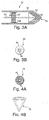
- FIGS. 3A and 3B depict an alternative embodiment of a delivery chamber suitable for use with the catheter system 10 shown in FIG. 1.
- the depicted delivery chamber 50 includes a cylindrical sidewall 58 that defines an interior space that houses a plunger 52.
- the plunger 52 includes a grooved plate 62 that can be rotatably driven along the threads 64 that extend along a portion of the sidewall 58. Accordingly, in this embodiment, the plunger 52 advances into the delivery chamber 50 as the plate 62 turns across, and travels over the threads 64.
- the distal end of the plunger 52 butts against a stack of nested drug delivery pellets 60 and forces the pellets 60 against the elongate flexible finger elements 54 that, as shown by FIG. 3B, define the port 56.
- the delivery chamber 50 implants drug pellets having a hollow, conical shape which facilitates the penetration of the implants 60 into the tissue wall.
- the plunger 52 can drive the pellets 60 through the port 56 and into the tissue wall.
- the flexible fingers 54 are biased to hold the pellets 60 within the chamber 50, however, the mechanical force applied by the plunger 52 will be sufficient to overcome the bias force of the fingers 54.
- a ratchet assembly, a rotary actuator, and/or optionally a detent can be employed to help the physician control the number of pellets being delivered into the tissue wall.
- the ratchet assembly or rotary actuator controls the distance the plunger 52 is driven into the chamber 50 and the detent provides a tactile sensation each time a pellet 60 is moved a predetermined distance.
- the delivery chamber 50 provides an alternative embodiment that allows for the implantation of larger pellets of drugs where the size of the pellet may require a delivery chamber that is too large to readily penetrate through a tissue wall. Accordingly, delivery chambers can be selectively developed for the implantation systems described herein based on the applications of interest and the size of the pellet being delivered. For example, in systems that implant microspheres of drugs having diameters of about 5-15 ⁇ m, the delivery chamber can be adapted to hold the microspheres in a fluid medium and a plunger assembly, or other suitable system, can be employed to flush the microspheres from the delivery chamber and into the tissue wall.
- the delivery chamber can be simply a hypodermic needle, and a syringe connected to the proximal end of the system can inject the fluid medium through a lumen in the catheter 12.
- Other delivery chambers can be employed with the systems described herein without departing from the scope hereof.
- the systems described above are capable of implanting pellets that contain a therapeutic agent.
- the therapeutic agent can be any compound that is biologically active and suitable for long term administration to a tissue or organ.
- the pellets described above can be formed as mini-spheres that are on the order of about 0.005 inches to about 0.040 inches in diameter. Particles of this size are capable of providing a therapeutically effective dose of agent and can remain where implanted, resisting fluid flux through the tissue wall.
- Cardiomyocytes introduced into damaged myocardium are understood in the following articles, incorporated herein by reference, to improve cardiac function.
- Jia et al. Transplanted Cardiomyocytes Survived in Scar Tissue and Improved Heart Function, Cell Transplantation vol. 5, page 42 (1997);
- Li et al. Natural History of Fetal Rat Cardiomyocytes Transplanted into Adult Rat Myocardial Scar Tissue, Circ. vol. 96, Supp. II, pages 179-187 (1997).
- other cells besides cardiomyocytes can be introduced into the damaged myocardium and will differentiate into cells that function like cardiomyocytes.
- Sources of cells include the skeletal muscle satellite cells and cells from the bone marrow, are described in the following articles, incorporated herein by reference.
- Chiu et al. Cellular Cardiomyoplasty: Myocardial Regeneration with Satellite Cell Implantation, Ann. Thorac. Surg. vol. 60, pages 12-18 (1995); Ferrari et al., Muscle Regeneration by Bone Marrow-derivedMyogenic Progenitors, Science vol. 279, pages 1528-1530 (March 6, 1998); Pennisi, Bone Marrow Cells May Provide Muscle Power, Science vol. 279, page 1456 (March 6, 1998).
- non-cardiomyocytes can be induced to differentiate into cells with structure and function analogous to cardiomyocytes, thus making a variety of cells available for transplantation into the damaged myocardium with the anticipation of functional benefit.
- the pellets described above can be adapted for delivery of a combination of therapeutic agents, including those agents capable of stimulating angiogenesis and those agents containing cells adapted for implantation in the myocardium.
- the pellet can be formed of a biocompatible material with a plurality of surfaces contacting the tissues of the myocardium and thereby promoting localized angiogenesis.
- a biocompatible material as described herein is one that does not incite systemic toxic reactions.
- the pellet contains an inner reservoir that delivers into the myocardium cells adapted for implantation.
- the pellet can be formed to contain at least one inner reservoir which contains at least one therapeutic agent. In this embodiment, the reservoir is permeable to at least one of the therapeutic agents it contains.
- cells adapted for implantation in the myocardium can be contained in this reservoir, to be delivered into the surrounding tissues by permeating the reservoir wall.
- the pellet or the reservoir within it may be made of a bioresorbable material, holding the cells inside until it has undergone some degree of resorption.
- the reservoir can contain molecular ligands that have affinity for surface markers of circulating myocyte precursor cells, so these cells become enclosed within the reservoir until their release.
- the delivery system includes a pellet made of a biocompatible material that contains at least one reservoir permeable to at least one of the therapeutic agents it contains. Within this pellet are at least two therapeutic agents, one agent capable of promoting angiogenesis and another agent containing cells adapted for implantation in the myocardium.
- the pellet contains at least two reservoirs, with one therapeutic agent disposed in each. These reservoirs can have different permeability characteristics, so there is differential release of the two agents.
- the pellet includes a drug releasing compound capable of releasing at least one therapeutic agent, while the other agent is retained within a reservoir contained within the pellet.
- the pellet or any reservoir within it can be made of a bioresorbable material.
- the reservoir can contain molecular ligands that have affinity for surface markers of circulating myocyte precursor cells, so these cells become enclosed within the reservoir until their release.
- pellets capable of acting as drug delivery implants are well known in the art.
- a solid pellet is formed from a biodegradable polymer that has been doped or "seeded" with the desired therapeutic agent.
- the polymer is a synthetic polymer, such as poly(lactic acid) or polyorthoesters, and is formed by solvent evaporation, spray drying, or phase separation.
- Such a pellet 70 is depicted in FIG. 4A.
- the polymer is capable of breaking down over time, allowing the drug to be released into the adjacent tissue.
- a sphere of a precious metal such as gold or platinum
- the drug-filled polymer 72 can be covered with the drug-filled polymer 72 in a thickness that provides the desired volume, dosage and/or time release profile.
- Other acceptable drug delivery implants include the "container" implant which is filled with a liquid drug.
- a wall of the container is at least partially made of a biodegradable polymer that permits passage of drug molecules at a certain rate. This design is common for injectable microspheres.
- One advantage is that it can work for drugs that are not amenable to doping in polymers because of heat processes or other incompatibilities.
- a radio-opaque metal core could be incorporated into this "container" type pellet to facilitate viewing.
- pellets delivered into or against the tissue wall can be coated with or include adhesive materials that adhere to tissue. Further, coatings can be provided that facilitate the absorption of the pellet into the tissue wall. Such coatings can include fumaric acid, sebacic acid and other similar materials.
- FIG. 4B depicts in more detail a pellet 76 suitable for delivery by the delivery chamber 50 depicted in FIGS. 3A and 3B.
- the pellet 76 is a hollow conical body that provides a pointed end that facilitates delivery of the pellet 76 into a tissue wall.
- the pellet 76 can carry a radio opaque marker (not shown) and, in one embodiment, the radio opaque marker comprises grains of a noble metal which are incorporated into the material of which the pellet 76 is formed.
- FIGS. 5 and 6 depict more explicitly one method according to the invention for implanting a therapeutic agent into a tissue wall.
- the depicted method is a cardiovascular treatment for restenosis that can occur in a coronary artery.
- the method includes the steps of employing an elongate flexible surgical instrument (e.g., a catheter) having a distal end that carries a delivery chamber 14.
- the distal end is inserted into a vascular system of a patient, such as by insertion via a femoral artery or vein.
- the delivery chamber 14 is guided through the patient's vascular system until the delivery chamber 14 is disposed within the heart, such as within the left ventricle. Once within the heart, the delivery chamber is employed to implant a therapeutic agent into the tissue of the heart.
- the physician can determine the therapeutic agent, or agents, to be implanted and the depot for the selected agents.
- the depot may be selected by considering, inter alia , the desired time of drug residence within the tissue and the desired dosage to be eluted during the course of the residence.
- the pellets can carry a plurality of therapeutic agents, either by solidifying a plurality of agents within the polymer coating of each pellet, or by providing pellets carrying different therapeutic agents. This latter practice allows the physician to load both active therapeutic agents and agents capable of activating therapeutic agents upon contact, or capable of degrading the polymer wall of an implanted pellet. This can allow for greater time delay before activation of an agent, and for greater selection in the delivery vehicle and the agents and drugs being delivered.
- the physician can select the delivery chamber to use and can pre-load the delivery chamber with a plurality of pellets, each of which can be a minisphere, a helical, conical pellet, a cylindrical container, or other device capable of being implanted into the myocardium.
- the physician can preload the delivery chamber 14 with the set of pellets that have been selected to deliver the proper depot of therapeutic agent to the tissue around an artery that is suffering from, or may suffer from, restentosis.
- pellets containing a desired therapeutic agent can be preloaded into the delivery system, which is provided to the physician as a sterile, disposable item.
- the treating physician Before delivering the preloaded delivery chamber 14 into the heart, the treating physician optionally performs a preliminary step of positioning a radio-opaque marker at the site of restenosis. This allows the treating physician to view the marker during delivery of the pellets.
- the marker can be a stent, or any viewable marker that will remain present at the site of the localized disease during the implanting of the drug delivery pellets.
- the marker can be the radio-opaque marker of a balloon being employed during a PTCA procedure.
- a PTCA procedure Specifically, as restenosis may arise from the site of the angioplasty, one practice of the invention performs the drug delivery at the same time as the angioplasty. In this procedure, the treating physician leaves the PTCA catheter in place, while the delivery implant system is guided to the target area.
- a radiopaque marker in the balloon gives fluoroscopic guidance during the implant procedure.
- the physician can guide the implant system along the appropriate delivery route until the catheter enters the interior of the patient's heart.
- the delivery chamber can approach target areas from within any chamber of the heart. Notably, the practices described herein allow that even septal arteries can be treated for cardiac conditions or to stimulate angiogenisis.
- the delivery chamber is shown as approaching the target area from the interior of the heart, and positioning the delivery chamber against the endocardial tissue over the myocardium.
- the physician drives the delivery chamber into the tissue and to the targeted area.
- the physician actuates the control mechanism and ejects a pellet from the delivery chamber, implanting the pellet within the targeted area of the myocardium.
- tunneled epicardial coronary arteries may represent a normal variant being recognized in up to 86% of vessels. Waller, Anatomy, Histology, and Pathology of the Major Epicardial Coronary Arteries Relevant to Echocardiographic Imaging Techniques, Journal of American Society of Echocardiographic Imaging, vol. 2 (1989).
- FIG. 6 illustrates a further realization of the present invention.
- FIG. 6 shows that it is desirable to implant the pellets as close as possible to the artery being treated, and that providing an array of implanted pellets about the periphery of the artery may provide sufficient localized elution of therapeutic agent to prevent restenosis.
- the pellets are implanted through a single point of entry through the myocardium. The physician manipulates the distal tip of the catheter to dispose the port of the delivery chamber at the depicted locations. At each location, a pellet is ejected from the delivery chamber and implanted into the myocardium.
- FIG. 7 depicts a further alternative embodiment of the invention.
- the depicted system 80 includes a short catheter 82 that carries a delivery chamber 84 at its distal end and that connects at its proximal end to a pistol grip control mechanism 88.
- the system 80 is adapted for use during an endoscopic procedure and to that end the depicted catheter 84 is a short catheter adapted to slide within a endoscopic port that has been placed through the chest and positioned abutting the pericardium.
- the delivery chamber 84 can be a delivery chamber as discussed above and can be dimensionally adapted to penetrate and extend through the pericardial sac. The delivery chamber can penetrate into the myocardium and thereby allow the physician to implant pellets into the myocardium.
- the catheter 82 can be a steerable catheter which allows the physician to bend the distal tip of the catheter 82 to place the delivery chamber 84 where needed.
- the catheter can include a deflectable tip, as is known in the art, which the physician can direct to the targeted area.
- Other modifications to the system 80 including providing the catheter with a fiber optic viewing device to allow the physician to view the interior of the pericardial sac, can be made without departing from the scope of the invention.
- the depicted pistol grip 88 provides the physician with a manual actuator that allows the physician to control the implanting of pellets within the myocardium.
- the pistol grip 88 can be a molded plastic assembly of the type well known in the art for actuating a mechanical assembly, such as the plunger assembly of the delivery chamber 14 described above.
- the techniques of the invention can be employed during an open chest procedure.
- the surgeon performing the open chest operation can employ a delivery device that includes a delivery chamber as described above to implant pellets into the myocardium.
- the physician can employ a hypodermic needle to inject a solution containing microspheres of a therapeutic agent.
- Other practices of the invention can be practiced without departing from the scope thereof.
- the systems and methods for implanting depots of therapeutic agents can be applied to conditions other than those relating to. cardiac failure.
- the systems described herein can be applied to the treatment of muscle tissue afflicted by insufficient circulation.
- the systems described herein are employed to deliver a human angiogenic growth factor, such as VGEF, which is understood to stimulate the growth of blood vessels.
- VGEF human angiogenic growth factor
- the systems described herein can promote the survival of muscle tissue that is moribund as a result of poor circulation due to failing or occluding blood vessels.
- the devices described herein can be used in cooperation with drilling elements or laser devices capable of forming an opening in a tissue wall, such as the myocardium.
- the delivery chamber can be inserted into the preformed openings for delivering a therapeutic agent therein.
- pellets according to the invention can include threaded exterior surfaces that facilitate implanting the pellet within a tissue wall. Accordingly, it will be understood that the invention is not to be limited to the embodiments disclosed herein, but is to be understood from the following claims, which are to be interpreted as broadly as allowed under the law.
Abstract
Description
- The invention relates to the local delivery of therapeutic agents, and more particularly, to systems and methods that deliver depots of therapeutic agents into a body of tissue to allow for the treatment of a variety of conditions, including coronary conditions and cardiovascular indications.
- Disease, injury and surgery can result in localized tissue damage and morbidity. For example, the principal treatment for occlusive vascular diseases is angioplasty, a procedure in which a balloon is inserted into the vessel and then inflated to dilate the area of narrowing. During inflation, the balloon can damage the vessel wall. It appears that as a result of this damage, in 30 to 50% of cases, the initial increase in lumen dimensions is followed by a localized re-narrowing (restenosis) of the vessel over a time of three to six months. Thus, restenosis can result in the dangerous and localized renarrowing of a patient's vessel at the site of the recent angioplasty. Like many other localized diseases, restenosis is complex and at present there is no clinically effective treatment for this disease. Gibbons et al., Molecular Therapies for Vascular Diseases, Science vol. 272, pages 617-780 (May 1996).
- Restenosis, like many other localized injuries and diseases, has responded poorly to pharmacological therapies and agents. Numerous pharmacological agents have been clinically tested, and none have demonstrated an unequivocal reduction in the incidence of restenosis. However, the failure of these pharmacological therapies may arise from the systemic intolerance of the doses required to achieve local beneficial effects or in the difficulty of providing controlled administration of proper dosages over time. Accordingly, one possible reason for the failure of these therapies is that submaximal doses of pharmacological agents are being administered to avoid the serious side-effects that might result from systemic administration of the proper dosage.
- To address this problem, various researchers have proposed methods for site-specific delivery of pharmacologic and molecular therapies. These methods include the direct deposition of therapeutic agents into the arterial wall through an intravascular delivery system, systemic administration of therapeutic agents that have a specific affinity for the injured or diseased tissue, and systemic administration of inactive agents followed by local activation.
- At present, systems exist that attempt to achieve localized delivery of therapeutic agents. These systems include dual balloon delivery systems that have proximal and distal balloons that are simultaneously inflated to isolate a treatment space within an arterial lumen. A catheter extends between the two balloons and includes a port that can admit within the treatment space between the balloons an aqueous medium, typically one containing a therapeutic agent. Pressure can be applied to the medium to create conditions conducive to intramural infusion. Other balloon-based localized delivery systems include porous balloon systems, hydrogel-coated balloons and porous balloons that have an interior metallic stent. Other systems include locally placed drug-loaded coated metallic stents and drug-filled polymer stents. Wilensky et al., Methods and Devices for Local Drug Delivery in Coronary and Peripheral Arteries, Trend Cardiovasc Med, vol. 3 (1993).
- Although these systems can provide working devices for local drug delivery, the efficacy of these devices turns on, and is limited by, a number of factors including the rate of fluid flux through the vascular wall, the residence time of the deposited agent and the local conditions and vasculature of the deposition site. Essentially, the success of these systems is limited by the amount of time that a delivered drug will stay resident locally before being carried downstream by circulating blood. Further, to the extent that these systems allow the therapeutic agent to be carried away, these systems run the risk of applying a therapeutic agent to areas of the patient's vasculature where such agents may not be beneficial. Additionally, these existing systems are limited by the amount of drug that can be delivered to the diseased site. Moreover, drug filled polymer stents have structural problems that argue against their use.
- Existing systems for local drug delivery, including direct deposition of therapeutic agents through an intravascular delivery system, systemic administration of therapeutic agents that have a specific affinity for the injured or diseased tissue, and systemic administration of inactive agents followed by local activation, all require a functioning vascular system for delivery of the therapeutic agent to the affected tissue. These systems, therefore, are inapplicable in conditions characterized by myocardial ischemia or infarction. When ischemic injury is of sufficient severity and duration, groups of involved cells die and myocardial infarction results. Within the ischemic area, not all cells are equally injured. As ischemia persists, there is wave-like progression of cell death or coagulation necrosis. The prospect for recovery decreases with increasing duration or severity of the ischemic insult. It is difficult to quantitate the extent to which ischemic injury will result in cell necrosis.
- Reperfusion can salvage injured tissue even after some cells have become necrotic. However, following reperfusion, cells that have been already injured are particularly vulnerable to further injury. This phenomenon, termed "reperfusion injury," paradoxically results in cellular necrosis when circulation returns to a cell population that survived the initial ischemic insult. Many factors contribute to this situation. The endothelium of vessels in the reperfused region have been damaged, causing platelet adherence and leukocyte activation with inflammatory sequelae. Oxygen free radicals are released by damaged cells, causing further cell and organelle damage. The sodium-potassium pump, damaged with the initial ischemia, can lose its regulatory ability and allow free water accumulation during reperfusion, resulting in cell swelling and rupture. Unstable and leaky cell membranes can also lead to calcium accumulation within the cytoplasm with uptake of calcium into mitochondria and formation of insoluble calcium-phosphate crystals. As a consequence, there may be a population of cells killed by the initial ischemic insult, and a further population killed following reperfusion.
- Both ischemia and infarction can adversely affect myocardial contractile function. The more extensive the injury, the more severe its impact on ventricular function. Following severe myocardial ischemia, there may be a reversible hypocontractile state called "hibemation," a condition of impaired contractility amenable to recovery (the so-called "stunned" myocardium, and frank myocardial infarction, characterized by cell death. Once a population of myocytes becomes necrotic, the injured tissue cannot regenerate itself; mature myocytes lack the capacity for cellular replication. The contribution these necrotic myocytes made to contractile function is, thus irreversibly lost. Restoration of functioning myocardium after frank infarction requires both a restoration of tissue perfusion and a replenishing of viable cells that can assume the contractile role of the infarcted tissues.
- In view of the variety of localized cardiovascular conditions affecting human health, it would be advantageous to develop other methods of treatment for patients having localized cardiovascular conditions and in particular to develop methods of treatment that reduce adverse side effects and have heightened efficacy. It would furthermore be advantageous to permit treatment of localized cardiovascular conditions resulting from myocardial ischemia and myocardial infarction through local delivery of therapeutic agents.
- It is therefore, an object of the invention to provide methods of treatment of a coronary artery or cardiac indication that provide a longer duration of drug pendency at the site of a localized disease.
- It is a further object of the invention to provide systems and methods that reduce or eliminate the downstream flow of a locally delivered agent.
- It is a further object of the invention to provide delivery of local therapeutic agents to areas of impaired vascularity.
- It is yet a further object of the invention to allow improvement of contractile function in infarcted myocardial tissue.
- Other objects of the invention will, in part, be obvious, and, in part, be shown from the following description of the systems and methods shown herein.
- To these ends, the invention provides systems and methods for implanting a depot into a tissue wall to thereby deliver a therapeutic agent selected for the condition being treated. In one embodiment, the invention provides systems and methods for delivering a therapeutic agent into the myocardial tissue wall for treating various vascular conditions including restenosis, ischemic tissue, and myocardial infarction. Other applications of the systems and methods described herein include the delivery of angiogenesis compounds that can be implanted into ischemic tissue; and/or antiarrhythmic drugs that can be implanted at the sites of conduction abnormalities. A further application of the systems and methods described herein includes the delivery of cells for implantation into the myocardium, accompanied by angiogenesis compounds that will promote local circulation. Accordingly, the agent being locally delivered can depend on the application at hand, and the term agent, or therapeutic agent, as employed herein will be understood to encompass any agent capable of being locally delivered including, but not limited to, pharmaceutical compositions or formulations, viral or non-viral vectors (e.g., adenovirus vectors, retroviral vectors and the like), implantable (genetically engineered) cells, plasmid-liposome complexes or other DNA delivery complexes, oligonucleotides or any other suitable composition compatible with the subject being treated.
- In one embodiment, the invention provides systems and methods for local delivery of at least two therapeutic agents, one of which promotes angiogenesis and the other of which contains cells adapted for implantation into the myocardium. The therapeutic agent that promotes angiogenesis can include any substance that induces the formation of blood vessels, including but not limited to such substances as vascular endothelial growth factor (VEGF), tumor angiogenesis factor (TAF), tumor necrosis factor (TNF), fibroblast growth factor (FGF), wound angiogenesis factor (WAF), other growth factors, and other substances including but not limited to angiogenin, fibrin, prostaglandin E and heparin. Cells adapted for implantation into the myocardium include, but are not limited to, cardiomyocytes and their precursors, skeletal myoblast-derived cells, fibroblasts, genetically modified fibroblasts and bone marrow stromal cells and their derivatives. Cells adapted for implantation into the myocardium can be subjected to genetic manipulation prior to or subsequent to implantation.
- In a further embodiment, the invention is understood as an apparatus for delivering therapeutic agents into the myocardium. These apparatus can comprise an outer mechanical element made of a biocompatible material which promotes angiogenesis locally by its contact with the myocardial tissues and further comprising an inner reservoir adapted for delivering cells adapted for implantation in the myocardial tissue. In another embodiment, the inner reservoir contains molecular ligands that possess specific affinity for the cell surface markers on circulating myocyte precursor cells, so that these cells are affixed within the reservoir and subsequently released. In a further embodiment, the biocompatible material of the apparatus comprises a drug releasing compound capable of releasing at least one therapeutic agent. In yet another embodiment, this therapeutic agent is capable of promoting angiogenesis. In a further embodiment, this apparatus is bioresorbable.
- The invention can also be understood to include apparatus for delivering at least two therapeutic agents comprising a body formed of a biocompatible material containing at least one reservoir permeable to at least one therapeutic agent. The biocompatible material of the delivery system can include a drug releasing compound capable of releasing at least one therapeutic agent. Therapeutic agents released by the drug releasing compound include, but are not limited to, those capable of promoting angiogenesis. In another embodiment, at least two therapeutic agents are disposed within separate reservoirs, each reservoir permeable to the therapeutic agent within it. In a further embodiment, this apparatus is bioresorbable.
- The apparatus can comprise an elongate flexible body having a proximal end and a distal end, a delivery chamber coupled to the distal end of the body and having a space for carrying the therapeutic agent, and a port for releasing the therapeutic agent therefrom. The apparatus can further include an actuator coupled to the distal delivery chamber and being capable of driving therapeutic agent through the port.
- The terms proximal and distal as used herein will be understood to describe opposite ends of a device or element, and generally will be employed so that proximal is understood as "away from the heart" and distal is understood as "towards the heart" or to mean "toward the physician" and "away from the physician" respectively.
- The foregoing and other objects and advantages of the invention will be appreciated more fully from the following further description thereof, with reference to the accompanying drawings wherein;
- FIG. 1 depicts one embodiment of a catheter having a delivery chamber carried at the distal end;
- FIGS. 2A and 2B depict in more detail the delivery chamber of the catheter depicted in FIG. 1;
- FIGS. 3A and 3B depict an alternative delivery chamber for use with the catheter of FIG. 1;
- FIGS. 4A and 4B depict two embodiments of pellets suitable for implantation by the catheter of FIG. 1;
- FIG. 5 depicts one method for delivering a therapeutic agent to the myocardium;
- FIG. 6 provides a cross-cut perspective of a coronary artery extending through the myocardium and having pellets of therapeutic agent disposed around the artery; and
- FIG. 7 depicts a local drug delivery device having a pistol grip and being suitable for use during an endoscopic procedure.
-
- To provide an overall understanding of the invention, the methods and devices illustrated herein are described with reference to the application of treating cardiac indications by implanting drug delivery pellets into myocardial tissue for the treatment of coronary artery restenosis, ischemic heart disease, cardiac conduction disturbances and other similar conditions. However, it will be understood that the systems and methods described herein are applicable to any condition that can benefit from the implanting of a depot of a therapeutic agent, and the invention is not to be limited to the applications illustrated herein. For example, the techniques herein are directly applicable for implanting therapeutic agents to stimulate angiogenesis. The techniques herein are also directly applicable to the methods for delivering therapeutic agents to infarcted myocardium where these therapeutic agents include substances for promoting angiogenesis and cells adapted for implantation in the myocardium. The techniques herein are further applicable to the manipulation of the cellular environment following ischemic injury, either to protect against reperfusion injury or to enhance recovery in the stunned myocardium.
- The depot implanting systems illustrated herein include catheter systems for delivery via the chambers of the heart, endoscopic systems for pericardial approach via minimally invasive trans-thoracic access, and systems for use during intraoperative pericardial approach during open-chest surgery. In one practice, the devices deliver a plurality of pellets that surround, or partially surround, an artery being treated. This is understood to achieve the effect of implanting a drug-filled ring around the artery. The pellets remain in the myocardial tissue, and can give off drug(s) for a selected time period and then be absorbed by the body. The systems described herein can implant pellets that contain radio-opaque markers to facilitate viewing the pellets by fluoroscopy during catheter delivery.
- Fig. 1 depicts one embodiment of a system for providing local delivery of a therapeutic agent. The
delivery device 10 includes acatheter 12, adelivery chamber 14,steering switches handle 18, and adelivery control switch 20. - The depicted
system 10 is a catheter system that can be guided through vascular access at the femoral artery or vein of a patient until thedelivery chamber 14 enters into the interior chambers of the patient's heart to implant a depot of drug within the myocardium. To that end, thecatheter 12 which extends between thedelivery chamber 14 and thehandle 18 can be approximately 175 cm to 200 cm in length and can include an elongated rotationally rigid, longitudinally flexible body optionally made of woven polyester fibers, stainless steel wires, thermoset or thermoplastic polymers or any other material suitable for use as a catheter shaft. The catheter can have a substantial uniform diameter of approximately 0.025 to 0.100 inches (.62 to 2.5 mm). - In the embodiment depicted in Fig. 1, the
catheter 12 is a steerable catheter that allows or facilitates the guiding of the catheter through the patient's vasculature and into the chamber of the patient's heart. Further, thesteerable catheter 12 allows the physician to bend the catheter once the catheter has entered into the interior of the heart, to thereby position thedelivery chamber 14 adjacent the area of the endocardial wall through which the delivery chamber is to penetrate. The steering capability of thecatheter 12 is illustrated by the bend located at the distal end of thecatheter 12. Steering catheters suitable for use with the present invention are known in the art, and include steering catheters employed in Electrophysiology procedures. Electrophysiology catheters typically provide steering through a combination of rotation and tip bending. - One suitable steerable catheter is described in U.S. Patent 5,656,029, which is incorporated herein by reference. This catheter provides an elongate flexible body that carries a bending mechanism at its distal end. The bending mechanism consists of a shape-memory element typically formed of Nitinol which is provided with a memory which makes it assume a straight condition when it is heated, such as by application of an electrical current. The shape memory element extends through the distal portion of the catheter and is adapted to remain straight along its full length in response to a current passing through the element. To control the location of the bending, an electrical bypass is slidably mounted about the bending element. The bypass element can be an elongate cylindrical sleeve formed of a conductive material and through which the bending element can extend. The bypass element can act as a short circuit that bypasses current away from the bending element. Accordingly, the bypass element prevents current from heating the bending element at the location of the bypass. Consequently, the bending element will bend at the location of the bypass. By allowing the bypass to be slid along the length of the bending element, the physician can select the location of the bypass, thereby selecting the location of bending. As the
delivery chamber 14 is carried at the distal extremity of thecatheter 12, this allows the physician to selectively position thedelivery chamber 14 within the interior of the patient's heart. - The bending elements and bypass elements described above are carried within the
catheter 12 and are not shown in Fig. 1, but however are described in detail in the above identified reference. Additionally, it is noted that although thecatheter 12 has been described with reference to one type of steerable catheter it will be apparent to one of ordinary skill in the art that other suitable steering mechanisms can be employed with the present invention including steering mechanisms that include actuating poles or wires that extend longitudinally through the catheter body. Moreover, it will be further understood that although the depictedcatheter 12 is optionally a steerable catheter, the devices of the invention are not to be limited to steerable devices, and will be understood to encompass conventional catheter systems as well. - Control of the depicted
catheter 12 and thedelivery chamber 14 is provided by the integrated hand-held control mechanism and handle 18 mounted on the proximal end of thecatheter 12. The control mechanism/handle 18 can be of various types, and the depictedhandle 18 is adapted for operating a steerable catheter wherein the bend of the catheter can be selectively controlled by the physician. To these ends, the hand-held control/handle 18 is dimensionally adapted to provide the treating physician with a device that is facile to manipulate and comfortable to hold. Additionally, the hand-held mechanism/handle 18 includes a set of control switches, 16a, 16b and 20 that allow the physician to control the steering of thecatheter 12 and the implanting of the depot.Switches catheter 12. Theswitch 16a can be a slidable switch that allows the physician to control the longitudinal position of the bend within the distal tip of the catheter. Theswitch 16a can activate the bending mechanism to cause the catheter tip to bend as needed. Thecontrol switch 20 can activate thedelivery chamber 14 to cause a pellet containing a therapeutic agent to be delivered into a tissue wall. - It will be apparent to one of ordinary skill in the art that other control mechanisms/handles can be employed with the systems of the invention without departing from the scope thereof. Specifically, other systems can include joystick controls for operating the steerable catheters and can include controls for rotating the angle at which the distal end of the catheter bends. Still other control mechanisms/handles can include pistol grips for providing manual activation of the
delivery chamber 14. Other modifications and additions can be made to the control mechanism/handle without departing from the scope of the invention. - Fig. 2A depicts in greater detail one
delivery chamber 14 which is suitable for being carried at the distal end of thecatheter 12 depicted in Fig. 1. Thedelivery chamber 14 is sized to hold the plurality ofminispheres 22, each of which contains a therapeutic agent. Theminispheres 22 are carried within aninterior chamber 24 which is bound at the proximal end by aplunger 33 and bound at the distal end by a wall formed of a plurality offlexible finger elements 36 that define aport 30. In the embodiment depicted in Fig. 2A, anoptional detent 34 is connected to a sidewall of thechamber 24 to provide a mechanical stop that prevents theminispheres 22 from freely exiting through theport 30. Upon application of mechanical force by theplunger 33, theminispheres 22 can be pushed over thedetent 34, for allowing oneminisphere 22 to be ejected throughport 30. - More specifically, the
plunger 33 depicted in Fig. 2A includes aplate 38 and anactuating rod 40. Theplate 38 is dimensioned to fill substantially the diameter ofinterior chamber 24 to provide thereby a surface that is adapted for forcing theminispheres 22 through thechamber 24 and out ofport 30. The actuatingrod 40 is connected to theplate 38 and provides a mechanical force to plate 38 to advance, or drive, theplate 38 distally into thechamber 24. In one embodiment, the actuatingrod 40 extends through thecatheter 12 and couples to the control mechanism/handle 18 at the proximal end ofdevice 10. In this embodiment, the control mechanism/handle 18 includes a mechanism that drives the actuatingrod 40 distally causingminispheres 22 to be delivered throughport 30. Optionally, this embodiment can include a control mechanism/handle 18 that incorporates a ratchet assembly that drives the actuatingrod 40 distally in discreet steps wherein a predetermined number of steps corresponds substantially to the diameter of one of theminispheres 22. For example, the depictedcontrol switch 20 can be a rotatable switch that allows for manual actuation of a ratchet assembly contained within the control mechanism/handle 18. The ratchet assembly allows the physician to drive theplunger 33 distally into thechamber 24 thereby driving theminisphere 22 out of theport 30. In this way, thedevice 10 can allow for the discreet and sequential delivery ofminispheres 22 from thedelivery chamber 14. - In an alternative embodiment of the invention, the
plunger 33 is threaded to mate with a threaded interior portion ofchamber 24. Manual or motor-driven rotation of actuatingrod 40 will advance or retract the plunger with a finer degree of control than that provided by strictly linear actuation. Such control over the travel distance of theplunger 33 into and out of theinterior chamber 24, gives control over the number ofminispheres 22 delivered throughport 30. - FIG. 2B provides a head-on perspective of the
delivery chamber 14, showing the distal most portion of thedelivery chamber 14 as viewed from a position along the longitudinal axis of thedelivery chamber 14. Together, FIGS. 2A and 2B show that the distal end of thedelivery chamber 14 includes aport 30 that is formed from the convergence of a plurality of flexiblearched fingers 36, each of which is formed from a resilient material and each of which is biased to hold theminispheres 22 within theinterior chamber 24. Upon action of theplunger 33 to move theminispheres 22 distally, thefingers 36 will yield to the axial pressure and release aminisphere 22. Additionally, in the embodiment depicted in FIG. 2A theoptional detent 34 provides further resistance that preventsminispheres 22 from exitingchamber 24 through theport 30 and for providing a tactile sensation that indicates when aminisphere 22 has been released, or has become available to be released, throughport 30. - The
delivery chamber 14 is adapted to facilitate the implantation of a depot of drug within a tissue wall. For example thedelivery chamber 14 can be sized and made of a material rigid enough to facilitate the penetration of the delivery chamber within a tissue wall. Accordingly, the depicteddelivery chamber 14 can be about 0.010 to 0.050 inches in diameter, and about .05 to .075 inches in length, to have a needle-like profile that is suitable for penetrating tissue. Additionally, the depicteddelivery chamber 14 can be formed of stainless steel or of plastic material that is sufficiently rigid to allow thedelivery chamber 14 to pass into a tissue wall. - FIGS. 3A and 3B depict an alternative embodiment of a delivery chamber suitable for use with the
catheter system 10 shown in FIG. 1. The depicteddelivery chamber 50 includes acylindrical sidewall 58 that defines an interior space that houses aplunger 52. Theplunger 52 includes a grooved plate 62 that can be rotatably driven along thethreads 64 that extend along a portion of thesidewall 58. Accordingly, in this embodiment, theplunger 52 advances into thedelivery chamber 50 as the plate 62 turns across, and travels over thethreads 64. The distal end of theplunger 52 butts against a stack of nesteddrug delivery pellets 60 and forces thepellets 60 against the elongateflexible finger elements 54 that, as shown by FIG. 3B, define theport 56. - The
delivery chamber 50 implants drug pellets having a hollow, conical shape which facilitates the penetration of theimplants 60 into the tissue wall. As shown, theplunger 52 can drive thepellets 60 through theport 56 and into the tissue wall. As discussed above, theflexible fingers 54 are biased to hold thepellets 60 within thechamber 50, however, the mechanical force applied by theplunger 52 will be sufficient to overcome the bias force of thefingers 54. Again as discussed above, a ratchet assembly, a rotary actuator, and/or optionally a detent, can be employed to help the physician control the number of pellets being delivered into the tissue wall. Specifically, the ratchet assembly or rotary actuator controls the distance theplunger 52 is driven into thechamber 50 and the detent provides a tactile sensation each time apellet 60 is moved a predetermined distance. - The
delivery chamber 50 provides an alternative embodiment that allows for the implantation of larger pellets of drugs where the size of the pellet may require a delivery chamber that is too large to readily penetrate through a tissue wall. Accordingly, delivery chambers can be selectively developed for the implantation systems described herein based on the applications of interest and the size of the pellet being delivered. For example, in systems that implant microspheres of drugs having diameters of about 5-15 µm, the delivery chamber can be adapted to hold the microspheres in a fluid medium and a plunger assembly, or other suitable system, can be employed to flush the microspheres from the delivery chamber and into the tissue wall. In this case, the delivery chamber can be simply a hypodermic needle, and a syringe connected to the proximal end of the system can inject the fluid medium through a lumen in thecatheter 12. Other delivery chambers can be employed with the systems described herein without departing from the scope hereof. - The systems described above are capable of implanting pellets that contain a therapeutic agent. The therapeutic agent can be any compound that is biologically active and suitable for long term administration to a tissue or organ. The pellets described above can be formed as mini-spheres that are on the order of about 0.005 inches to about 0.040 inches in diameter. Particles of this size are capable of providing a therapeutically effective dose of agent and can remain where implanted, resisting fluid flux through the tissue wall.
- An understanding of the technologies upon which the present invention draws is based on articles in the scientific literature, such as those cited below which are herein incorporated by reference. It is a realization of the present invention that ischemia can be treated by promoting angiogenesis in the ischemic area. It is a further realization of the present invention that the introduction of cardiomyocyte precursor cells into a damaged area of the myocardium can result in the production of functioning myocardial elements.
- Molecular bases for vascular growth and remodeling have been described in the scientific literature. Folkman and D'Amore, Blood Vessel Formation: What is its Molecular Basis? Cell vol. 87, pages 1153-1155 (December 27, 1996); Kim et al., Inhibition of Vascular Endothelial Growth Factor-induced Angiogenesis Suppresses Tumor Growth In Vivo, Nature vol. 362, pages 841-844 (April, 1993); Knighton et al., Wound Healing Angiogenesis: Indirect Stimulation by Basic Fibroblast Growth Factor, J. Trauma vol. 30, pages S134-S144 (December, 1990). These findings have been applied to the myocardium, showing that increased neovascularization can be induced by angiogenic therapy. Folkman, Angiogenic Therapy of the Human Heart, Circ. vol. 97, pages 628-629 (1998); Schumacher et al., Induction of Neoangiogenesis in Ischemic Myocardium by Human Growth Factors, Circ. vol. 97, pages 645-650 (1998). The abovementioned articles, describing the basis for applying the techniques of angiogenesis to the ischemic myocardium, are hereby incorporated by reference. In an area of the myocardium where the native circulation has been impaired, it is understood that promoting angiogenesis can lead to the ingrowth of new blood vessels and thereby can help restore the level ofperfusion needed for effective tissue nutrition.
- In light of the fact that mammalian cardiomyocytes are terminally differentiated early in the development of the heart, it is understood that the myocardium cannot regenerate its muscle cells after myocardial infarction. Smith and Claycomb, Adult Rat Cardiomyocyte Proliferation Assay, In Vitro Cell Dev. Biol. vol. 33, pages 428-431 (June, 1997); Parker and Schneider, Growth Factors, Proto-oncogenes, and Plasticity of the Cardiac Phenotype, Ann. Rev. Physiol. vol. 53, pages 179-200 (1991). These articles, incorporated herein by reference, describe the ways in which the functioning myocardium responds to the loss of viable cardiomyocytes following ischemic injury. Terminal differentiation, and the factors that regulate it, are described by Olwin et al, Are Fibroblast Growth Factors Regulators of Myogenesis In Vivo? Progress in Growth Factor Research, vol. 5, pages 145-158 (1994), incorporated herein by reference. It has been further described that transplanted myocytes can be introduced into an area of the myocardium that has been damaged by ischemia or infarction. Li et al., Cardiomyocyte Transplantation Improves Heart Function, Ann. Thor. Surg. vol. 62, pages 654-661 (1996). According to this article, incorporated herein by reference, cardiomyocytes are understood to survive and function when placed within an area of injured or necrotic myocardium, or within myocardial scar tissue. It has been further described that genetically modified cardiomyocytes transplanted into damaged myocardium survive in ischemic areas. Aoki et al., Survival of Grafts of Genetically Modified Cardiac Myocytes Transfected with FITC-labeled Oligodeoxynucleotides and the Beta-Galactosidase Gene in the Noninfarcted Area but not in the Myocardial Infarcted Area, Gene Therapy vol. 4, pages 120-127 (1997); Gojo et al., Transplantation of Genetically Marked Cardiac Muscle Cells, J. Thorac. Cardiovasc. Surg. vol. 113, pages 10-18 (1997); Gojo et al, Ex Vivo Gene Transfer into Myocardium Using Replication-defective Retrovirus, Cell Transplantation, vol. 5, pages S81-S84 (1996). These articles, incorporated herein by reference, further teach the possibility of genetic modification of cells implanted within the myocardium whereby the implanted cells would express factors that would contribute to the clinical treatment of the damaged area. Growth factors expressed by genetically modified cells are understood to produce angiogenesis in vivo. Ueno et al., Adenovirus-Mediated Expression of the Secreted Form of Basic Fibroblast Growth Factor (FGF-2) Induces Cellular Proliferation and Angiogenesis In Vivo, Arterioscler. Thromb. Vasc. Biol. vol. 17, pages 2453-2460 (1997).
- Cardiomyocytes introduced into damaged myocardium are understood in the following articles, incorporated herein by reference, to improve cardiac function. Jia et al., Transplanted Cardiomyocytes Survived in Scar Tissue and Improved Heart Function, Cell Transplantation vol. 5, page 42 (1997); Li et al., Natural History of Fetal Rat Cardiomyocytes Transplanted into Adult Rat Myocardial Scar Tissue, Circ. vol. 96, Supp. II, pages 179-187 (1997). It is further understood, however, that other cells besides cardiomyocytes can be introduced into the damaged myocardium and will differentiate into cells that function like cardiomyocytes. Sources of cells, include the skeletal muscle satellite cells and cells from the bone marrow, are described in the following articles, incorporated herein by reference. Chiu et al., Cellular Cardiomyoplasty: Myocardial Regeneration with Satellite Cell Implantation, Ann. Thorac. Surg. vol. 60, pages 12-18 (1995); Ferrari et al., Muscle Regeneration by Bone Marrow-derivedMyogenic Progenitors, Science vol. 279, pages 1528-1530 (March 6, 1998); Pennisi, Bone Marrow Cells May Provide Muscle Power, Science vol. 279, page 1456 (March 6, 1998). According to these publications, non-cardiomyocytes can be induced to differentiate into cells with structure and function analogous to cardiomyocytes, thus making a variety of cells available for transplantation into the damaged myocardium with the anticipation of functional benefit.
- Methods described in the abovementioned publications for introducing cells into the myocardium have been substantially limited to direct intramural needle injections of cell suspensions under direct visualization in the operative setting. An alternative method of intra-arterial or intraventricular injection of cell suspensions into the bloodstream has been described that resulted in successful engraftation of cells within the myocardium. Robinson et al., Arterial Delivery of Genetically Labeled Skeletal Myoblasts to the Murine Heart: Long-term Survival and Phenotypic Modification of Implanted Myoblasts, Cell Transplantation vol. 5, pages 77-91 (1996). Microsphere technology, well-known to practitioners in the art, has been described for the delivery of angiogenic factors to the heart. Arras et al., The Delivery of Angiogenic Factors to the Heart by Microsphere Therapy, Nature Biotechnology vol. 16, pages 159-162 (1998). It is a realization of the present invention that the delivery of a combination of therapeutic agents, including those agents adapted for stimulating angiogenesis and those agents containing cells adapted for implantation in the myocardium, can be provided by a system of pellets that are introduced into the myocardium. The teachings of the abovementioned articles are incorporated herein by reference.
- The pellets described above can be adapted for delivery of a combination of therapeutic agents, including those agents capable of stimulating angiogenesis and those agents containing cells adapted for implantation in the myocardium. In one embodiment, the pellet can be formed of a biocompatible material with a plurality of surfaces contacting the tissues of the myocardium and thereby promoting localized angiogenesis. A biocompatible material as described herein is one that does not incite systemic toxic reactions. In this embodiment, the pellet contains an inner reservoir that delivers into the myocardium cells adapted for implantation. In yet another embodiment, the pellet can be formed to contain at least one inner reservoir which contains at least one therapeutic agent. In this embodiment, the reservoir is permeable to at least one of the therapeutic agents it contains. For example, cells adapted for implantation in the myocardium can be contained in this reservoir, to be delivered into the surrounding tissues by permeating the reservoir wall. Alternatively, the pellet or the reservoir within it may be made of a bioresorbable material, holding the cells inside until it has undergone some degree of resorption. The reservoir can contain molecular ligands that have affinity for surface markers of circulating myocyte precursor cells, so these cells become enclosed within the reservoir until their release.
- In another embodiment, the delivery system includes a pellet made of a biocompatible material that contains at least one reservoir permeable to at least one of the therapeutic agents it contains. Within this pellet are at least two therapeutic agents, one agent capable of promoting angiogenesis and another agent containing cells adapted for implantation in the myocardium. In one embodiment, the pellet contains at least two reservoirs, with one therapeutic agent disposed in each. These reservoirs can have different permeability characteristics, so there is differential release of the two agents. In one embodiment, the pellet includes a drug releasing compound capable of releasing at least one therapeutic agent, while the other agent is retained within a reservoir contained within the pellet. The pellet or any reservoir within it can be made of a bioresorbable material. The reservoir can contain molecular ligands that have affinity for surface markers of circulating myocyte precursor cells, so these cells become enclosed within the reservoir until their release.
- Techniques and materials for forming pellets capable of acting as drug delivery implants are well known in the art. In one practice, a solid pellet is formed from a biodegradable polymer that has been doped or "seeded" with the desired therapeutic agent. Typically, the polymer is a synthetic polymer, such as poly(lactic acid) or polyorthoesters, and is formed by solvent evaporation, spray drying, or phase separation. Such a
pellet 70 is depicted in FIG. 4A. The polymer is capable of breaking down over time, allowing the drug to be released into the adjacent tissue. To aid in visualizing the implant by fluoroscopy or x-ray, a sphere of a precious metal, such as gold or platinum, can be covered with the drug-filledpolymer 72 in a thickness that provides the desired volume, dosage and/or time release profile. Other acceptable drug delivery implants include the "container" implant which is filled with a liquid drug. A wall of the container is at least partially made of a biodegradable polymer that permits passage of drug molecules at a certain rate. This design is common for injectable microspheres. One advantage is that it can work for drugs that are not amenable to doping in polymers because of heat processes or other incompatibilities. A radio-opaque metal core could be incorporated into this "container" type pellet to facilitate viewing. - Additionally, pellets delivered into or against the tissue wall can be coated with or include adhesive materials that adhere to tissue. Further, coatings can be provided that facilitate the absorption of the pellet into the tissue wall. Such coatings can include fumaric acid, sebacic acid and other similar materials.
- FIG. 4B depicts in more detail a
pellet 76 suitable for delivery by thedelivery chamber 50 depicted in FIGS. 3A and 3B. Thepellet 76 is a hollow conical body that provides a pointed end that facilitates delivery of thepellet 76 into a tissue wall. Optionally, thepellet 76 can carry a radio opaque marker (not shown) and, in one embodiment, the radio opaque marker comprises grains of a noble metal which are incorporated into the material of which thepellet 76 is formed. - It will be apparent to one of ordinary skill in the art that other drug delivery implants can be employed with the systems described herein, including disc shaped pills or cylindrical implants that incorporate a solid, drug-filled polymer core with the container-type biodegradable polymer wall. One such implant is described in U.S. patent 5,629,008, which is incorporated herein in its entirety by reference.
- FIGS. 5 and 6 depict more explicitly one method according to the invention for implanting a therapeutic agent into a tissue wall. The depicted method is a cardiovascular treatment for restenosis that can occur in a coronary artery. The method includes the steps of employing an elongate flexible surgical instrument (e.g., a catheter) having a distal end that carries a
delivery chamber 14. The distal end is inserted into a vascular system of a patient, such as by insertion via a femoral artery or vein. Thedelivery chamber 14 is guided through the patient's vascular system until thedelivery chamber 14 is disposed within the heart, such as within the left ventricle. Once within the heart, the delivery chamber is employed to implant a therapeutic agent into the tissue of the heart. - In a first step the physician can determine the therapeutic agent, or agents, to be implanted and the depot for the selected agents. The depot may be selected by considering, inter alia, the desired time of drug residence within the tissue and the desired dosage to be eluted during the course of the residence. Optionally, the pellets can carry a plurality of therapeutic agents, either by solidifying a plurality of agents within the polymer coating of each pellet, or by providing pellets carrying different therapeutic agents. This latter practice allows the physician to load both active therapeutic agents and agents capable of activating therapeutic agents upon contact, or capable of degrading the polymer wall of an implanted pellet. This can allow for greater time delay before activation of an agent, and for greater selection in the delivery vehicle and the agents and drugs being delivered. Once the agents are selected, the physician can select the delivery chamber to use and can pre-load the delivery chamber with a plurality of pellets, each of which can be a minisphere, a helical, conical pellet, a cylindrical container, or other device capable of being implanted into the myocardium. The physician can preload the
delivery chamber 14 with the set of pellets that have been selected to deliver the proper depot of therapeutic agent to the tissue around an artery that is suffering from, or may suffer from, restentosis. Alternatively, pellets containing a desired therapeutic agent can be preloaded into the delivery system, which is provided to the physician as a sterile, disposable item. - Before delivering the preloaded
delivery chamber 14 into the heart, the treating physician optionally performs a preliminary step of positioning a radio-opaque marker at the site of restenosis. This allows the treating physician to view the marker during delivery of the pellets. The marker can be a stent, or any viewable marker that will remain present at the site of the localized disease during the implanting of the drug delivery pellets. - In one practice, the marker can be the radio-opaque marker of a balloon being employed during a PTCA procedure. Specifically, as restenosis may arise from the site of the angioplasty, one practice of the invention performs the drug delivery at the same time as the angioplasty. In this procedure, the treating physician leaves the PTCA catheter in place, while the delivery implant system is guided to the target area. A radiopaque marker in the balloon gives fluoroscopic guidance during the implant procedure.
- At this time, the physician can guide the implant system along the appropriate delivery route until the catheter enters the interior of the patient's heart. The delivery chamber can approach target areas from within any chamber of the heart. Notably, the practices described herein allow that even septal arteries can be treated for cardiac conditions or to stimulate angiogenisis. In FIG. 5, the delivery chamber is shown as approaching the target area from the interior of the heart, and positioning the delivery chamber against the endocardial tissue over the myocardium. Upon positioning the delivery chamber adjacent the interior tissue wall of the heart, the physician drives the delivery chamber into the tissue and to the targeted area. The physician actuates the control mechanism and ejects a pellet from the delivery chamber, implanting the pellet within the targeted area of the myocardium.
- It is a realization of the present invention that the practices described herein are often suitable for arteries normally considered epicardial, with little surrounding myocardial tissue or subepicardial fat in which to implant the drug delivery pellets. Specifically, researchers have noted that tunneled epicardial coronary arteries may represent a normal variant being recognized in up to 86% of vessels. Waller, Anatomy, Histology, and Pathology of the Major Epicardial Coronary Arteries Relevant to Echocardiographic Imaging Techniques, Journal of American Society of Echocardiographic Imaging, vol. 2 (1989).
- FIG. 6 illustrates a further realization of the present invention. FIG. 6 shows that it is desirable to implant the pellets as close as possible to the artery being treated, and that providing an array of implanted pellets about the periphery of the artery may provide sufficient localized elution of therapeutic agent to prevent restenosis. In one practice, the pellets are implanted through a single point of entry through the myocardium. The physician manipulates the distal tip of the catheter to dispose the port of the delivery chamber at the depicted locations. At each location, a pellet is ejected from the delivery chamber and implanted into the myocardium.
- FIG. 7 depicts a further alternative embodiment of the invention. The depicted
system 80 includes ashort catheter 82 that carries adelivery chamber 84 at its distal end and that connects at its proximal end to a pistolgrip control mechanism 88. - The
system 80 is adapted for use during an endoscopic procedure and to that end the depictedcatheter 84 is a short catheter adapted to slide within a endoscopic port that has been placed through the chest and positioned abutting the pericardium. Thedelivery chamber 84 can be a delivery chamber as discussed above and can be dimensionally adapted to penetrate and extend through the pericardial sac. The delivery chamber can penetrate into the myocardium and thereby allow the physician to implant pellets into the myocardium. Optionally, thecatheter 82 can be a steerable catheter which allows the physician to bend the distal tip of thecatheter 82 to place thedelivery chamber 84 where needed. Alternatively, the catheter can include a deflectable tip, as is known in the art, which the physician can direct to the targeted area. Other modifications to thesystem 80, including providing the catheter with a fiber optic viewing device to allow the physician to view the interior of the pericardial sac, can be made without departing from the scope of the invention. - The depicted
pistol grip 88 provides the physician with a manual actuator that allows the physician to control the implanting of pellets within the myocardium. Thepistol grip 88 can be a molded plastic assembly of the type well known in the art for actuating a mechanical assembly, such as the plunger assembly of thedelivery chamber 14 described above. - In a further practice, the techniques of the invention can be employed during an open chest procedure. Specifically, the surgeon performing the open chest operation can employ a delivery device that includes a delivery chamber as described above to implant pellets into the myocardium. Additionally, in this practice, the physician can employ a hypodermic needle to inject a solution containing microspheres of a therapeutic agent. Other practices of the invention can be practiced without departing from the scope thereof.
- Moreover, the systems and methods for implanting depots of therapeutic agents can be applied to conditions other than those relating to. cardiac failure. For example, the systems described herein can be applied to the treatment of muscle tissue afflicted by insufficient circulation. In one practice, the systems described herein are employed to deliver a human angiogenic growth factor, such as VGEF, which is understood to stimulate the growth of blood vessels. Thus, the systems described herein can promote the survival of muscle tissue that is moribund as a result of poor circulation due to failing or occluding blood vessels.
- Those skilled in the art will know or be able to ascertain using no more than routine experimentation, many equivalents to the embodiments and practices described herein. For example, the devices described herein can be used in cooperation with drilling elements or laser devices capable of forming an opening in a tissue wall, such as the myocardium. The delivery chamber can be inserted into the preformed openings for delivering a therapeutic agent therein. Further, pellets according to the invention can include threaded exterior surfaces that facilitate implanting the pellet within a tissue wall. Accordingly, it will be understood that the invention is not to be limited to the embodiments disclosed herein, but is to be understood from the following claims, which are to be interpreted as broadly as allowed under the law.
Claims (12)
- An implant for delivering at least one therapeutic agent to the myocardium comprising:a body (22,60,70,76) formed from a biocompatible material with a plurality of surfaces contacting the tissues of the myocardium to promote localized angiogenesis; anda reservoir disposed within said body adapted for delivering cells capable of implantation in said myocardial tissue.
- An implant according to Claim 1, wherein said biocompatible material comprises a drug releasing compound for releasing at least one therapeutic agent.
- An implant according to Claim 2, wherein said drug releasing compound releases at least one therapeutic agent capable of promoting angiogenesis.
- An implant according to any preceding claim, wherein said biocompatible material is a bioresorbable material.
- An implant according to Claim 1, wherein said body includes at least a first and a second member, each having a different therapeutic agent.
- An implant according to any preceding claim, wherein said reservoir contains molecular ligands, said ligands possessing specific affinity for cell surface markers expressed on circulating myocyte precursor cells, whereby said myocyte precursor cells become affixed within said reservoir.
- An implant according to any of Claims 1 to 6, wherein said cells for implantation include myoblast-derived cells.
- An implant according to any of Claims 1 to 6, wherein said cells for implantation include cardiomyocytes.
- An implant according to any of Claims 1 to 6, wherein said cells for implantation include precursors to cardiomyocytes.
- An implant according to any of Claims 1 to 6, wherein said cells for implantation include genetically modified fibroblasts.
- An implant according to any of Claims 1 to 6, wherein said cells for implantation include precursors to fibroblasts.
- An implant according to any of Claims 1 to 6, wherein said cells for implantation include bone marrow stromal cells.
Applications Claiming Priority (3)
| Application Number | Priority Date | Filing Date | Title |
|---|---|---|---|
| US159834 | 1998-09-24 | ||
| US09/159,834 US6689121B1 (en) | 1998-09-24 | 1998-09-24 | Systems and methods for treating ischemia |
| EP99949916A EP1115452B1 (en) | 1998-09-24 | 1999-09-24 | System for treating ischemia |
Related Parent Applications (1)
| Application Number | Title | Priority Date | Filing Date |
|---|---|---|---|
| EP99949916A Division EP1115452B1 (en) | 1998-09-24 | 1999-09-24 | System for treating ischemia |
Publications (2)
| Publication Number | Publication Date |
|---|---|
| EP1484081A1 true EP1484081A1 (en) | 2004-12-08 |
| EP1484081B1 EP1484081B1 (en) | 2007-08-15 |
Family
ID=22574269
Family Applications (2)
| Application Number | Title | Priority Date | Filing Date |
|---|---|---|---|
| EP99949916A Expired - Lifetime EP1115452B1 (en) | 1998-09-24 | 1999-09-24 | System for treating ischemia |
| EP04021459A Expired - Lifetime EP1484081B1 (en) | 1998-09-24 | 1999-09-24 | System for treating ischemia |
Family Applications Before (1)
| Application Number | Title | Priority Date | Filing Date |
|---|---|---|---|
| EP99949916A Expired - Lifetime EP1115452B1 (en) | 1998-09-24 | 1999-09-24 | System for treating ischemia |
Country Status (7)
| Country | Link |
|---|---|
| US (2) | US6689121B1 (en) |
| EP (2) | EP1115452B1 (en) |
| JP (1) | JP2002541879A (en) |
| AU (1) | AU6268899A (en) |
| DE (2) | DE69936890T2 (en) |
| ES (1) | ES2234307T3 (en) |
| WO (1) | WO2000016848A1 (en) |
Cited By (11)
| Publication number | Priority date | Publication date | Assignee | Title |
|---|---|---|---|---|
| WO2007105239A1 (en) * | 2006-03-14 | 2007-09-20 | Luciano Ciuro | The system for the implantation of cardiac staminal cells with the ' ciuro method' |
| US7704222B2 (en) | 1998-09-10 | 2010-04-27 | Jenavalve Technology, Inc. | Methods and conduits for flowing blood from a heart chamber to a blood vessel |
| US10993805B2 (en) | 2008-02-26 | 2021-05-04 | Jenavalve Technology, Inc. | Stent for the positioning and anchoring of a valvular prosthesis in an implantation site in the heart of a patient |
| US11065138B2 (en) | 2016-05-13 | 2021-07-20 | Jenavalve Technology, Inc. | Heart valve prosthesis delivery system and method for delivery of heart valve prosthesis with introducer sheath and loading system |
| US11185405B2 (en) | 2013-08-30 | 2021-11-30 | Jenavalve Technology, Inc. | Radially collapsible frame for a prosthetic valve and method for manufacturing such a frame |
| US11197754B2 (en) | 2017-01-27 | 2021-12-14 | Jenavalve Technology, Inc. | Heart valve mimicry |
| US11337800B2 (en) | 2015-05-01 | 2022-05-24 | Jenavalve Technology, Inc. | Device and method with reduced pacemaker rate in heart valve replacement |
| US11357624B2 (en) | 2007-04-13 | 2022-06-14 | Jenavalve Technology, Inc. | Medical device for treating a heart valve insufficiency |
| US11517431B2 (en) | 2005-01-20 | 2022-12-06 | Jenavalve Technology, Inc. | Catheter system for implantation of prosthetic heart valves |
| US11564794B2 (en) | 2008-02-26 | 2023-01-31 | Jenavalve Technology, Inc. | Stent for the positioning and anchoring of a valvular prosthesis in an implantation site in the heart of a patient |
| US11589981B2 (en) | 2010-05-25 | 2023-02-28 | Jenavalve Technology, Inc. | Prosthetic heart valve and transcatheter delivered endoprosthesis comprising a prosthetic heart valve and a stent |
Families Citing this family (16)
| Publication number | Priority date | Publication date | Assignee | Title |
|---|---|---|---|---|
| US6309384B1 (en) | 1999-02-01 | 2001-10-30 | Adiana, Inc. | Method and apparatus for tubal occlusion |
| US8702727B1 (en) | 1999-02-01 | 2014-04-22 | Hologic, Inc. | Delivery catheter with implant ejection mechanism |
| US6719805B1 (en) * | 1999-06-09 | 2004-04-13 | C. R. Bard, Inc. | Devices and methods for treating tissue |
| DE10215751B4 (en) * | 2002-04-10 | 2006-09-28 | Mathys Medizinaltechnik Ag | Device for implanting marking bodies in a bone |
| EP1536743A2 (en) * | 2002-08-27 | 2005-06-08 | SDGI Holdings, Inc. | Systems and methods for intravertebral reduction |
| EP2087905A2 (en) * | 2003-08-08 | 2009-08-12 | Novo Nordisk A/S | Interleukin-20 for treating and diagnosing conditions associated with neovascularisation |
| US20090036840A1 (en) * | 2006-11-22 | 2009-02-05 | Cytyc Corporation | Atraumatic ball tip and side wall opening |
| US20090081276A1 (en) * | 2007-08-13 | 2009-03-26 | Eben Alsberg | Bioresorbable implant composition |
| US8470360B2 (en) | 2008-04-18 | 2013-06-25 | Warsaw Orthopedic, Inc. | Drug depots having different release profiles for reducing, preventing or treating pain and inflammation |
| CA2699597C (en) * | 2007-09-28 | 2016-10-11 | Ut-Battelle, Llc | Treatment of cardiovascular disorders using the cell differentiation signaling protein nell1 |
| US20090263456A1 (en) * | 2008-04-18 | 2009-10-22 | Warsaw Orthopedic, Inc. | Methods and Compositions for Reducing Preventing and Treating Adhesives |
| WO2011031299A1 (en) * | 2009-08-28 | 2011-03-17 | Mount Sinai School Of Medicine Of New York University | Intrapericardial injections |
| US8231619B2 (en) | 2010-01-22 | 2012-07-31 | Cytyc Corporation | Sterilization device and method |
| US8550086B2 (en) | 2010-05-04 | 2013-10-08 | Hologic, Inc. | Radiopaque implant |
| US9205241B2 (en) * | 2011-07-12 | 2015-12-08 | Warsaw Orthopedic, Inc. | Medical devices and methods comprising an adhesive material |
| US20140371685A1 (en) * | 2013-06-14 | 2014-12-18 | Peter Troesch | Cannula |
Citations (7)
| Publication number | Priority date | Publication date | Assignee | Title |
|---|---|---|---|---|
| US5180366A (en) * | 1990-10-10 | 1993-01-19 | Woods W T | Apparatus and method for angioplasty and for preventing re-stenosis |
| WO1994027612A1 (en) * | 1993-05-20 | 1994-12-08 | Baylor College Of Medicine | Genetic therapy for cardiovascular disease |
| WO1995033511A1 (en) * | 1994-06-07 | 1995-12-14 | C.R. Bard, Inc. | Method and device for long-term delivery of drugs |
| WO1996020698A2 (en) * | 1995-01-05 | 1996-07-11 | The Board Of Regents Acting For And On Behalf Of The University Of Michigan | Surface-modified nanoparticles and method of making and using same |
| US5656029A (en) | 1992-12-01 | 1997-08-12 | Cardiac Pathways Corporation | Steerable catheter with adjustable bend location and/or radius and method |
| WO1997045105A1 (en) * | 1996-05-24 | 1997-12-04 | Angiotech Pharmaceuticals, Inc. | Compositions and methods for treating or preventing diseases of body passageways |
| EP0853921A2 (en) * | 1996-12-27 | 1998-07-22 | Eclipse Surgical Technologies, Inc. | Laser assisted drug delivery |
Family Cites Families (132)
| Publication number | Priority date | Publication date | Assignee | Title |
|---|---|---|---|---|
| FR1278969A (en) | 1960-01-28 | 1961-12-15 | Dunlop Sa | Improvements to pneumatic tires |
| US3680544A (en) | 1970-09-09 | 1972-08-01 | James P Shinnick | Transthoracic cannula-type device for cardiopulmonary resuscitation |
| US3995617A (en) | 1972-05-31 | 1976-12-07 | Watkins David H | Heart assist method and catheter |
| US3991750A (en) | 1975-04-28 | 1976-11-16 | Syntex Corporation | Dromostanolone propionate implant pellet useful for producing weight gains in animals and suppressing estrus in female animals |
| WO1980000007A1 (en) | 1978-06-02 | 1980-01-10 | A Rockey | Medical sleeve |
| US4307722A (en) | 1979-08-14 | 1981-12-29 | Evans Joseph M | Dilators for arterial dilation |
| US4396021A (en) | 1980-12-15 | 1983-08-02 | Baumgartner George C | Surgical instrument and process |
| US4451253A (en) | 1980-12-18 | 1984-05-29 | Harman Sherman M | Means and method for administering medicinals |
| SE445884B (en) | 1982-04-30 | 1986-07-28 | Medinvent Sa | DEVICE FOR IMPLANTATION OF A RODFORM PROTECTION |
| US4546499A (en) | 1982-12-13 | 1985-10-15 | Possis Medical, Inc. | Method of supplying blood to blood receiving vessels |
| US4503569A (en) | 1983-03-03 | 1985-03-12 | Dotter Charles T | Transluminally placed expandable graft prosthesis |
| US4774949A (en) | 1983-06-14 | 1988-10-04 | Fogarty Thomas J | Deflector guiding catheter |
| US4548206A (en) | 1983-07-21 | 1985-10-22 | Cook, Incorporated | Catheter wire guide with movable mandril |
| US4582181A (en) | 1983-08-12 | 1986-04-15 | Advanced Cardiovascular Systems, Inc. | Steerable dilatation catheter |
| RU2026640C1 (en) | 1984-09-13 | 1995-01-20 | Адолий Яковлевич Кононов | Method for surgical treatment of ischemia |
| US5114414A (en) | 1984-09-18 | 1992-05-19 | Medtronic, Inc. | Low profile steerable catheter |
| US4580568A (en) | 1984-10-01 | 1986-04-08 | Cook, Incorporated | Percutaneous endovascular stent and method for insertion thereof |
| US4658817A (en) | 1985-04-01 | 1987-04-21 | Children's Hospital Medical Center | Method and apparatus for transmyocardial revascularization using a laser |
| JPH066113B2 (en) | 1985-05-29 | 1994-01-26 | 三井東圧化学株式会社 | Catheter with pressure sensor |
| FR2583985B1 (en) | 1985-06-27 | 1988-08-05 | Nivarox Sa | STYLET FOR ELECTRODE IMPLANTABLE IN THE BODY |
| US4785815A (en) | 1985-10-23 | 1988-11-22 | Cordis Corporation | Apparatus for locating and ablating cardiac conduction pathways |
| US4733665C2 (en) | 1985-11-07 | 2002-01-29 | Expandable Grafts Partnership | Expandable intraluminal graft and method and apparatus for implanting an expandable intraluminal graft |
| US4681110A (en) | 1985-12-02 | 1987-07-21 | Wiktor Dominik M | Catheter arrangement having a blood vessel liner, and method of using it |
| US4700692A (en) | 1985-12-23 | 1987-10-20 | Baumgartner George C | Surgical implantation method and apparatus |
| US4665918A (en) | 1986-01-06 | 1987-05-19 | Garza Gilbert A | Prosthesis system and method |
| US4649922A (en) | 1986-01-23 | 1987-03-17 | Wiktor Donimik M | Catheter arrangement having a variable diameter tip and spring prosthesis |
| EP0257091B1 (en) | 1986-02-24 | 1993-07-28 | Robert E. Fischell | An intravascular stent and percutaneous insertion system |
| US4852580A (en) | 1986-09-17 | 1989-08-01 | Axiom Medical, Inc. | Catheter for measuring bioimpedance |
| US4861330A (en) | 1987-03-12 | 1989-08-29 | Gene Voss | Cardiac assist device and method |
| US4813925A (en) | 1987-04-21 | 1989-03-21 | Medical Engineering Corporation | Spiral ureteral stent |
| US4894057A (en) | 1987-06-19 | 1990-01-16 | Howes Randolph M | Flow enhanced multi-lumen venous catheter device |
| DK163713C (en) | 1987-09-02 | 1992-09-07 | Ole Gyring Nieben | DEVICE FOR THE POSITION OF A PARTICULAR CATHETTE IN A BODY |
| US4920980A (en) | 1987-09-14 | 1990-05-01 | Cordis Corporation | Catheter with controllable tip |
| US5487739A (en) | 1987-11-17 | 1996-01-30 | Brown University Research Foundation | Implantable therapy systems and methods |
| US5266073A (en) | 1987-12-08 | 1993-11-30 | Wall W Henry | Angioplasty stent |
| US4889137A (en) | 1988-05-05 | 1989-12-26 | The United States Of America As Reprsented By The Department Of Health And Human Services | Method for improved use of heart/lung machine |
| US4917102A (en) | 1988-09-14 | 1990-04-17 | Advanced Cardiovascular Systems, Inc. | Guidewire assembly with steerable adjustable tip |
| US4950227A (en) | 1988-11-07 | 1990-08-21 | Boston Scientific Corporation | Stent delivery system |
| US4917666A (en) | 1988-11-14 | 1990-04-17 | Medtronic Versaflex, Inc. | Steerable thru-lumen catheter |
| US5328470A (en) | 1989-03-31 | 1994-07-12 | The Regents Of The University Of Michigan | Treatment of diseases by site-specific instillation of cells or site-specific transformation of cells and kits therefor |
| US4995857A (en) | 1989-04-07 | 1991-02-26 | Arnold John R | Left ventricular assist device and method for temporary and permanent procedures |
| DE3915636C1 (en) | 1989-05-12 | 1990-04-26 | Sass, Wolfgang, Dr. | |
| US5056517A (en) | 1989-07-24 | 1991-10-15 | Consiglio Nazionale Delle Ricerche | Biomagnetically localizable multipurpose catheter and method for magnetocardiographic guided intracardiac mapping, biopsy and ablation of cardiac arrhythmias |
| US4997431A (en) | 1989-08-30 | 1991-03-05 | Angeion Corporation | Catheter |
| EP0419729A1 (en) | 1989-09-29 | 1991-04-03 | Siemens Aktiengesellschaft | Position finding of a catheter by means of non-ionising fields |
| US5049138A (en) | 1989-11-13 | 1991-09-17 | Boston Scientific Corporation | Catheter with dissolvable tip |
| US5158548A (en) | 1990-04-25 | 1992-10-27 | Advanced Cardiovascular Systems, Inc. | Method and system for stent delivery |
| US5087243A (en) | 1990-06-18 | 1992-02-11 | Boaz Avitall | Myocardial iontophoresis |
| US5040543A (en) | 1990-07-25 | 1991-08-20 | C. R. Bard, Inc. | Movable core guidewire |
| US5172699A (en) | 1990-10-19 | 1992-12-22 | Angelase, Inc. | Process of identification of a ventricular tachycardia (VT) active site and an ablation catheter system |
| US5389096A (en) | 1990-12-18 | 1995-02-14 | Advanced Cardiovascular Systems | System and method for percutaneous myocardial revascularization |
| WO1992007525A1 (en) | 1990-10-31 | 1992-05-14 | Baxter International Inc. | Close vascularization implant material |
| US5344454A (en) | 1991-07-24 | 1994-09-06 | Baxter International Inc. | Closed porous chambers for implanting tissue in a host |
| CA2054961C (en) | 1990-12-14 | 1997-09-30 | James R. Gross | Multilumen catheter |
| US5380316A (en) | 1990-12-18 | 1995-01-10 | Advanced Cardiovascular Systems, Inc. | Method for intra-operative myocardial device revascularization |
| US5312456A (en) | 1991-01-31 | 1994-05-17 | Carnegie Mellon University | Micromechanical barb and method for making the same |
| NZ242509A (en) | 1991-05-01 | 1996-03-26 | Univ Columbia | Myocardial revascularisation using laser |
| US5190058A (en) | 1991-05-22 | 1993-03-02 | Medtronic, Inc. | Method of using a temporary stent catheter |
| US5324325A (en) | 1991-06-27 | 1994-06-28 | Siemens Pacesetter, Inc. | Myocardial steroid releasing lead |
| US5358474A (en) | 1991-07-02 | 1994-10-25 | Intermed, Inc. | Subcutaneous drug delivery device |
| US5562613A (en) | 1991-07-02 | 1996-10-08 | Intermed, Inc. | Subcutaneous drug delivery device |
| US5452733A (en) | 1993-02-22 | 1995-09-26 | Stanford Surgical Technologies, Inc. | Methods for performing thoracoscopic coronary artery bypass |
| WO1993006792A1 (en) | 1991-10-04 | 1993-04-15 | Scimed Life Systems, Inc. | Biodegradable drug delivery vascular stent |
| US5256146A (en) | 1991-10-11 | 1993-10-26 | W. D. Ensminger | Vascular catheterization system with catheter anchoring feature |
| US5269326A (en) | 1991-10-24 | 1993-12-14 | Georgetown University | Method for transvenously accessing the pericardial space via the right auricle for medical procedures |
| US5167614A (en) | 1991-10-29 | 1992-12-01 | Medical Engineering Corporation | Prostatic stent |
| US5372600A (en) | 1991-10-31 | 1994-12-13 | Instent Inc. | Stent delivery systems |
| DE69228680D1 (en) | 1991-12-23 | 1999-04-22 | Sims Deltec Inc | GUIDE WIRE DEVICE WITH LOCATOR |
| US5176626A (en) | 1992-01-15 | 1993-01-05 | Wilson-Cook Medical, Inc. | Indwelling stent |
| CA2087132A1 (en) | 1992-01-31 | 1993-08-01 | Michael S. Williams | Stent capable of attachment within a body lumen |
| US5290295A (en) | 1992-07-15 | 1994-03-01 | Querals & Fine, Inc. | Insertion tool for an intraluminal graft procedure |
| US5287861A (en) | 1992-10-30 | 1994-02-22 | Wilk Peter J | Coronary artery by-pass method and associated catheter |
| US5409019A (en) | 1992-10-30 | 1995-04-25 | Wilk; Peter J. | Coronary artery by-pass method |
| US5429144A (en) | 1992-10-30 | 1995-07-04 | Wilk; Peter J. | Coronary artery by-pass method |
| US5682906A (en) | 1993-02-22 | 1997-11-04 | Heartport, Inc. | Methods of performing intracardiac procedures on an arrested heart |
| JPH08507715A (en) | 1993-03-18 | 1996-08-20 | シーダーズ サイナイ メディカル センター | Drug-inducing and releasable polymeric coatings for bioartificial components |
| US5464650A (en) | 1993-04-26 | 1995-11-07 | Medtronic, Inc. | Intravascular stent and method |
| US20020055710A1 (en) | 1998-04-30 | 2002-05-09 | Ronald J. Tuch | Medical device for delivering a therapeutic agent and method of preparation |
| US5425757A (en) | 1993-05-21 | 1995-06-20 | Tiefenbrun; Jonathan | Aortic surgical procedure |
| US5409004A (en) | 1993-06-11 | 1995-04-25 | Cook Incorporated | Localization device with radiopaque markings |
| US5458615A (en) | 1993-07-06 | 1995-10-17 | Advanced Cardiovascular Systems, Inc. | Stent delivery system |
| US5391199A (en) | 1993-07-20 | 1995-02-21 | Biosense, Inc. | Apparatus and method for treating cardiac arrhythmias |
| US5562619A (en) | 1993-08-19 | 1996-10-08 | Boston Scientific Corporation | Deflectable catheter |
| US5405376A (en) | 1993-08-27 | 1995-04-11 | Medtronic, Inc. | Method and apparatus for ablation |
| US5464404A (en) | 1993-09-20 | 1995-11-07 | Abela Laser Systems, Inc. | Cardiac ablation catheters and method |
| RU2063179C1 (en) | 1993-10-06 | 1996-07-10 | Новосибирский медицинский институт | Multifunctional scalpel-tunnelizer |
| US5558091A (en) | 1993-10-06 | 1996-09-24 | Biosense, Inc. | Magnetic determination of position and orientation |
| WO1995010989A1 (en) | 1993-10-19 | 1995-04-27 | Scimed Life Systems, Inc. | Intravascular stent pump |
| US5602301A (en) | 1993-11-16 | 1997-02-11 | Indiana University Foundation | Non-human mammal having a graft and methods of delivering protein to myocardial tissue |
| US5476505A (en) | 1993-11-18 | 1995-12-19 | Advanced Cardiovascular Systems, Inc. | Coiled stent and delivery system |
| EP0666065A1 (en) | 1994-02-02 | 1995-08-09 | Katsushi Mori | Stent for biliary, urinary or vascular system |
| US5453090A (en) | 1994-03-01 | 1995-09-26 | Cordis Corporation | Method of stent delivery through an elongate softenable sheath |
| US5441516A (en) | 1994-03-03 | 1995-08-15 | Scimed Lifesystems Inc. | Temporary stent |
| EP0757562A1 (en) | 1994-04-29 | 1997-02-12 | W.L. Gore & Associates, Inc. | Improved blood contact surfaces using endothelium on a subendothelial extracellular matrix |
| FR2725615B1 (en) | 1994-10-17 | 1997-06-13 | Caffiniere Jean Yves De | BONE ANCHORING DEVICE FOR FIXATION THREADS USED IN ORTHOPEDIC SURGERY |
| US5614578A (en) | 1994-10-28 | 1997-03-25 | Alza Corporation | Injection-molded dosage form |
| EP0714640A1 (en) | 1994-11-28 | 1996-06-05 | Advanced Cardiovascular Systems, Inc. | System and method for delivering multiple stents |
| US5814062A (en) | 1994-12-22 | 1998-09-29 | Target Therapeutics, Inc. | Implant delivery assembly with expandable coupling/decoupling mechanism |
| US5514176A (en) | 1995-01-20 | 1996-05-07 | Vance Products Inc. | Pull apart coil stent |
| US5551427A (en) | 1995-02-13 | 1996-09-03 | Altman; Peter A. | Implantable device for the effective elimination of cardiac arrhythmogenic sites |
| US5792453A (en) | 1995-02-28 | 1998-08-11 | The Regents Of The University Of California | Gene transfer-mediated angiogenesis therapy |
| US5643308A (en) | 1995-02-28 | 1997-07-01 | Markman; Barry Stephen | Method and apparatus for forming multiple cavities for placement of hair grafts |
| US5614206A (en) | 1995-03-07 | 1997-03-25 | Wright Medical Technology, Inc. | Controlled dissolution pellet containing calcium sulfate |
| CA2171896C (en) | 1995-03-17 | 2007-05-15 | Scott C. Anderson | Multi-anchor stent |
| US5571168A (en) | 1995-04-05 | 1996-11-05 | Scimed Lifesystems Inc | Pull back stent delivery system |
| US5666970A (en) | 1995-05-02 | 1997-09-16 | Heart Rhythm Technologies, Inc. | Locking mechanism for catheters |
| JP3318578B2 (en) | 1995-05-26 | 2002-08-26 | サーモディックス,インコーポレイティド | Methods for promoting endothelialization and implantable products |
| CA2178541C (en) | 1995-06-07 | 2009-11-24 | Neal E. Fearnot | Implantable medical device |
| US5840059A (en) | 1995-06-07 | 1998-11-24 | Cardiogenesis Corporation | Therapeutic and diagnostic agent delivery |
| US5797870A (en) | 1995-06-07 | 1998-08-25 | Indiana University Foundation | Pericardial delivery of therapeutic and diagnostic agents |
| US5861032A (en) | 1996-01-31 | 1999-01-19 | Surface Genesis, Inc. | Medical device having a biocompatible coating and oxidation method of coupling therefor |
| US5769843A (en) | 1996-02-20 | 1998-06-23 | Cormedica | Percutaneous endomyocardial revascularization |
| US5690643A (en) | 1996-02-20 | 1997-11-25 | Leocor, Incorporated | Stent delivery system |
| US5810836A (en) | 1996-03-04 | 1998-09-22 | Myocardial Stents, Inc. | Device and method for trans myocardial revascularization (TMR) |
| US5782823A (en) | 1996-04-05 | 1998-07-21 | Eclipse Surgical Technologies, Inc. | Laser device for transmyocardial revascularization procedures including means for enabling a formation of a pilot hole in the epicardium |
| CA2207570A1 (en) | 1996-06-13 | 1997-12-13 | Eclipse Surgical Technologies, Inc. | Intraoperative myocardial device and stimulation procedure |
| US5662124A (en) | 1996-06-19 | 1997-09-02 | Wilk Patent Development Corp. | Coronary artery by-pass method |
| US5755682A (en) | 1996-08-13 | 1998-05-26 | Heartstent Corporation | Method and apparatus for performing coronary artery bypass surgery |
| US5655548A (en) | 1996-09-16 | 1997-08-12 | Circulation, Inc. | Method for treatment of ischemic heart disease by providing transvenous myocardial perfusion |
| JP3754145B2 (en) | 1996-09-20 | 2006-03-08 | 株式会社カネカメディックス | Medical wire having in-vivo indwelling member |
| US5785702A (en) | 1996-10-15 | 1998-07-28 | Eclipse Surgical Technologies, Inc. | Method for non-synchronous laser-assisted transmyocardial revascularization |
| US5756127A (en) | 1996-10-29 | 1998-05-26 | Wright Medical Technology, Inc. | Implantable bioresorbable string of calcium sulfate beads |
| US5971993A (en) | 1996-11-07 | 1999-10-26 | Myocardial Stents, Inc. | System for delivery of a trans myocardial device to a heart wall |
| US5899915A (en) | 1996-12-02 | 1999-05-04 | Angiotrax, Inc. | Apparatus and method for intraoperatively performing surgery |
| US5807384A (en) | 1996-12-20 | 1998-09-15 | Eclipse Surgical Technologies, Inc. | Transmyocardial revascularization (TMR) enhanced treatment for coronary artery disease |
| DE19703482A1 (en) | 1997-01-31 | 1998-08-06 | Ernst Peter Prof Dr M Strecker | Stent |
| US6045565A (en) | 1997-11-04 | 2000-04-04 | Scimed Life Systems, Inc. | Percutaneous myocardial revascularization growth factor mediums and method |
| US5817101A (en) | 1997-03-13 | 1998-10-06 | Schneider (Usa) Inc | Fluid actuated stent delivery system |
| US5980548A (en) | 1997-10-29 | 1999-11-09 | Kensey Nash Corporation | Transmyocardial revascularization system |
| US6197324B1 (en) * | 1997-12-18 | 2001-03-06 | C. R. Bard, Inc. | System and methods for local delivery of an agent |
| US6251418B1 (en) * | 1997-12-18 | 2001-06-26 | C.R. Bard, Inc. | Systems and methods for local delivery of an agent |
| WO1999066978A1 (en) | 1998-06-22 | 1999-12-29 | Neovasys, Inc. | Method, implant and delivery system for enhancing blood flow in tissue |
-
1998
- 1998-09-24 US US09/159,834 patent/US6689121B1/en not_active Expired - Fee Related
-
1999
- 1999-09-24 EP EP99949916A patent/EP1115452B1/en not_active Expired - Lifetime
- 1999-09-24 AU AU62688/99A patent/AU6268899A/en not_active Abandoned
- 1999-09-24 JP JP2000573807A patent/JP2002541879A/en not_active Withdrawn
- 1999-09-24 DE DE69936890T patent/DE69936890T2/en not_active Expired - Fee Related
- 1999-09-24 ES ES99949916T patent/ES2234307T3/en not_active Expired - Lifetime
- 1999-09-24 DE DE69922226T patent/DE69922226T2/en not_active Expired - Fee Related
- 1999-09-24 EP EP04021459A patent/EP1484081B1/en not_active Expired - Lifetime
- 1999-09-24 WO PCT/US1999/022392 patent/WO2000016848A1/en active IP Right Grant
-
2004
- 2004-01-29 US US10/767,551 patent/US20040186423A1/en not_active Abandoned
Patent Citations (7)
| Publication number | Priority date | Publication date | Assignee | Title |
|---|---|---|---|---|
| US5180366A (en) * | 1990-10-10 | 1993-01-19 | Woods W T | Apparatus and method for angioplasty and for preventing re-stenosis |
| US5656029A (en) | 1992-12-01 | 1997-08-12 | Cardiac Pathways Corporation | Steerable catheter with adjustable bend location and/or radius and method |
| WO1994027612A1 (en) * | 1993-05-20 | 1994-12-08 | Baylor College Of Medicine | Genetic therapy for cardiovascular disease |
| WO1995033511A1 (en) * | 1994-06-07 | 1995-12-14 | C.R. Bard, Inc. | Method and device for long-term delivery of drugs |
| WO1996020698A2 (en) * | 1995-01-05 | 1996-07-11 | The Board Of Regents Acting For And On Behalf Of The University Of Michigan | Surface-modified nanoparticles and method of making and using same |
| WO1997045105A1 (en) * | 1996-05-24 | 1997-12-04 | Angiotech Pharmaceuticals, Inc. | Compositions and methods for treating or preventing diseases of body passageways |
| EP0853921A2 (en) * | 1996-12-27 | 1998-07-22 | Eclipse Surgical Technologies, Inc. | Laser assisted drug delivery |
Cited By (15)
| Publication number | Priority date | Publication date | Assignee | Title |
|---|---|---|---|---|
| US7704222B2 (en) | 1998-09-10 | 2010-04-27 | Jenavalve Technology, Inc. | Methods and conduits for flowing blood from a heart chamber to a blood vessel |
| US7736327B2 (en) | 1998-09-10 | 2010-06-15 | Jenavalve Technology, Inc. | Methods and conduits for flowing blood from a heart chamber to a blood vessel |
| US8216174B2 (en) | 1998-09-10 | 2012-07-10 | Jenavalve Technology, Inc. | Methods and conduits for flowing blood from a heart chamber to a blood vessel |
| US8597226B2 (en) | 1998-09-10 | 2013-12-03 | Jenavalve Technology, Inc. | Methods and conduits for flowing blood from a heart chamber to a blood vessel |
| US11517431B2 (en) | 2005-01-20 | 2022-12-06 | Jenavalve Technology, Inc. | Catheter system for implantation of prosthetic heart valves |
| WO2007105239A1 (en) * | 2006-03-14 | 2007-09-20 | Luciano Ciuro | The system for the implantation of cardiac staminal cells with the ' ciuro method' |
| US11357624B2 (en) | 2007-04-13 | 2022-06-14 | Jenavalve Technology, Inc. | Medical device for treating a heart valve insufficiency |
| US11564794B2 (en) | 2008-02-26 | 2023-01-31 | Jenavalve Technology, Inc. | Stent for the positioning and anchoring of a valvular prosthesis in an implantation site in the heart of a patient |
| US11154398B2 (en) | 2008-02-26 | 2021-10-26 | JenaValve Technology. Inc. | Stent for the positioning and anchoring of a valvular prosthesis in an implantation site in the heart of a patient |
| US10993805B2 (en) | 2008-02-26 | 2021-05-04 | Jenavalve Technology, Inc. | Stent for the positioning and anchoring of a valvular prosthesis in an implantation site in the heart of a patient |
| US11589981B2 (en) | 2010-05-25 | 2023-02-28 | Jenavalve Technology, Inc. | Prosthetic heart valve and transcatheter delivered endoprosthesis comprising a prosthetic heart valve and a stent |
| US11185405B2 (en) | 2013-08-30 | 2021-11-30 | Jenavalve Technology, Inc. | Radially collapsible frame for a prosthetic valve and method for manufacturing such a frame |
| US11337800B2 (en) | 2015-05-01 | 2022-05-24 | Jenavalve Technology, Inc. | Device and method with reduced pacemaker rate in heart valve replacement |
| US11065138B2 (en) | 2016-05-13 | 2021-07-20 | Jenavalve Technology, Inc. | Heart valve prosthesis delivery system and method for delivery of heart valve prosthesis with introducer sheath and loading system |
| US11197754B2 (en) | 2017-01-27 | 2021-12-14 | Jenavalve Technology, Inc. | Heart valve mimicry |
Also Published As
| Publication number | Publication date |
|---|---|
| WO2000016848A1 (en) | 2000-03-30 |
| EP1115452A1 (en) | 2001-07-18 |
| DE69922226D1 (en) | 2004-12-30 |
| AU6268899A (en) | 2000-04-10 |
| JP2002541879A (en) | 2002-12-10 |
| US20040186423A1 (en) | 2004-09-23 |
| DE69922226T2 (en) | 2005-11-10 |
| ES2234307T3 (en) | 2005-06-16 |
| EP1115452B1 (en) | 2004-11-24 |
| US6689121B1 (en) | 2004-02-10 |
| DE69936890D1 (en) | 2007-09-27 |
| EP1484081B1 (en) | 2007-08-15 |
| DE69936890T2 (en) | 2008-04-30 |
Similar Documents
| Publication | Publication Date | Title |
|---|---|---|
| US6689121B1 (en) | Systems and methods for treating ischemia | |
| US6251418B1 (en) | Systems and methods for local delivery of an agent | |
| US6197324B1 (en) | System and methods for local delivery of an agent | |
| US5997509A (en) | Minimally invasive gene therapy delivery device and method | |
| US8529550B2 (en) | Implant delivery catheter system and methods for its use | |
| EP1301228B1 (en) | Deployment system for myocardial cellular material | |
| US8388581B2 (en) | System for treating the heart with potentially embolic agents through a right heart approach | |
| JP2003529409A (en) | Drug delivery catheter attached to tissue and method of use | |
| AU2002320369A1 (en) | Methods for controlled depth injections into interior body cavities | |
| WO2003006089A1 (en) | Methods for controlled depth injections into interior body cavities | |
| JP2003506143A (en) | Implant and drug supply device | |
| EP1588731B1 (en) | Local drug delivery catheter | |
| WO2001010315A9 (en) | Gene therapy platformed needle and method of administering a therapeutic solution to a heart |
Legal Events
| Date | Code | Title | Description |
|---|---|---|---|
| PUAI | Public reference made under article 153(3) epc to a published international application that has entered the european phase |
Free format text: ORIGINAL CODE: 0009012 |
|
| AC | Divisional application: reference to earlier application |
Ref document number: 1115452 Country of ref document: EP Kind code of ref document: P |
|
| AK | Designated contracting states |
Kind code of ref document: A1 Designated state(s): DE ES FR GB IT |
|
| 17P | Request for examination filed |
Effective date: 20050512 |
|
| AKX | Designation fees paid |
Designated state(s): DE ES FR GB IT |
|
| RTI1 | Title (correction) |
Free format text: SYSTEM FOR TREATING ISCHEMIA |
|
| GRAP | Despatch of communication of intention to grant a patent |
Free format text: ORIGINAL CODE: EPIDOSNIGR1 |
|
| GRAS | Grant fee paid |
Free format text: ORIGINAL CODE: EPIDOSNIGR3 |
|
| GRAA | (expected) grant |
Free format text: ORIGINAL CODE: 0009210 |
|
| AC | Divisional application: reference to earlier application |
Ref document number: 1115452 Country of ref document: EP Kind code of ref document: P |
|
| AK | Designated contracting states |
Kind code of ref document: B1 Designated state(s): DE ES FR GB IT |
|
| REG | Reference to a national code |
Ref country code: GB Ref legal event code: FG4D |
|
| REF | Corresponds to: |
Ref document number: 69936890 Country of ref document: DE Date of ref document: 20070927 Kind code of ref document: P |
|
| ET | Fr: translation filed | ||
| PG25 | Lapsed in a contracting state [announced via postgrant information from national office to epo] |
Ref country code: ES Free format text: LAPSE BECAUSE OF FAILURE TO SUBMIT A TRANSLATION OF THE DESCRIPTION OR TO PAY THE FEE WITHIN THE PRESCRIBED TIME-LIMIT Effective date: 20071126 |
|
| PLBE | No opposition filed within time limit |
Free format text: ORIGINAL CODE: 0009261 |
|
| STAA | Information on the status of an ep patent application or granted ep patent |
Free format text: STATUS: NO OPPOSITION FILED WITHIN TIME LIMIT |
|
| 26N | No opposition filed |
Effective date: 20080516 |
|
| PGFP | Annual fee paid to national office [announced via postgrant information from national office to epo] |
Ref country code: FR Payment date: 20080915 Year of fee payment: 10 |
|
| PGFP | Annual fee paid to national office [announced via postgrant information from national office to epo] |
Ref country code: GB Payment date: 20080924 Year of fee payment: 10 |
|
| PGFP | Annual fee paid to national office [announced via postgrant information from national office to epo] |
Ref country code: DE Payment date: 20081002 Year of fee payment: 10 |
|
| GBPC | Gb: european patent ceased through non-payment of renewal fee |
Effective date: 20090924 |
|
| REG | Reference to a national code |
Ref country code: FR Ref legal event code: ST Effective date: 20100531 |
|
| PG25 | Lapsed in a contracting state [announced via postgrant information from national office to epo] |
Ref country code: FR Free format text: LAPSE BECAUSE OF NON-PAYMENT OF DUE FEES Effective date: 20090930 Ref country code: DE Free format text: LAPSE BECAUSE OF NON-PAYMENT OF DUE FEES Effective date: 20100401 |
|
| PG25 | Lapsed in a contracting state [announced via postgrant information from national office to epo] |
Ref country code: GB Free format text: LAPSE BECAUSE OF NON-PAYMENT OF DUE FEES Effective date: 20090924 |
|
| PG25 | Lapsed in a contracting state [announced via postgrant information from national office to epo] |
Ref country code: IT Free format text: LAPSE BECAUSE OF NON-PAYMENT OF DUE FEES Effective date: 20070930 |