-
This invention relates to the monitoring and
prediction of the remaining useful life of an electric
storage battery, such as a Lead acid battery. It also
relates to determination of the state of charge of the
battery. It is thought that the present invention will
assist current supply management for systems using
batteries as alternative or primary sources of electric
power.
-
The state of charge of a battery is a measure of the
instantaneous energy level of the battery and is
expressed as a percentage from 0%, when the battery is
flat, to 100% for a fully charged battery, which has not
yet been used. For a Lead acid battery the state of
charge can be determined from the open circuit terminal
voltage of the battery, as there is an approximately
linear relationship between the two.
-
However the instantaneous state of charge of the
battery does not give a good indication of the future
life of the battery, or how many times it can be
recharged before it will fail. Each time a Lead acid
battery is discharged, and recharged, irreversible
changes occur in the structure of the active components.
These irreversible changes progressively degrade the
ability of the battery usefully to store electrical
energy. Eventually the ability of the battery to usefully
store electrical energy is degraded to the point that the
battery has to be replaced.
-
In this application the remaining "life" of the
battery and similar terms refer to the remaining useful
life (usually extending over many discharge/charging
cycles) before this gradual degradation means that the
battery can no longer function adequately and should be
replaced. The point at which the battery should be
replaced can be derived from the manufacturer's
specification or criteria set by the battery's user. It
may depend on the particular application and may be
defined, for example, by the lowest acceptable battery
capacity when the battery is fully charged. For example,
the maximum acceptable degradation may be 60% of
capacity; i.e. when due to degradation the battery, when
fully charged, has a state of charge of only 60% (i.e.
60% of the maximum available capacity of the battery when
it was new).
-
Previously the state of health of an electric
storage battery has been monitored by measurements of the
electrolyte specific gravity, internal resistance and
battery voltage during a controlled discharge test. These
methods require specialist test equipment, cannot be
applied frequently and need detailed technical knowledge
for the interpretation of the results.
-
Furthermore, it is intrinsic to sealed batteries
that electrolyte is not accessible in the battery cells,
and that the battery voltage is dependent on the
conditions under which the battery is being used. These
conditions include the ambient temperature and whether
the battery is subject to a charge current or supplying a
discharge current. Thus, when the state of charge is
calculated from the terminal voltage, it is difficult to
get a reliable reading of the terminal voltage from which
to calculate the state of charge.
-
Another difficulty with the above approach is that
the deliverable electrical capacity and the impedance of
an electric storage battery do not change significantly
during the majority of the life of the battery.
Measurement of these characteristics as isolated events
can only provide information about the current capability
of the battery and does not allow predictive evaluation.
-
Towards the end of the battery's life, the capacity
and impedance values of an electric storage battery
change more rapidly and comparisons with earlier tests
have been used to indicate that failure is imminent. When
such measurements are made repeatedly, through the life
of the battery, it is often difficult to assure that the
tests are performed reproducibly and that records are
maintained reliably enough for accurate technical
evaluation to be performed.
-
GB2377833 discloses a battery monitor which
indicates battery health by illuminating one of five LEDs
on a display (each LED corresponding to a level of health
from good to poor). The level of battery health is
periodically estimated by determining the battery
terminal voltage level as a percentage of the calibration
voltage level measured when the battery was first used
and adjusting this figure based on the change in battery
internal resistance and voltage drop in service compared
to that when the battery was first used. The resultant
figure is used to decide which of the five LEDs to
illuminate. However because the indicator is based on a
comparison of instantaneous readings with the initial
calibration, the battery's history is not properly taken
into account. Therefore for some purposes the monitor may
not give as accurate or timely prediction of the
battery's future performance as desired. As noted above,
in most cases the maximum state of charge and internal
resistance of the battery only change significantly near
the end of a battery's life, which limits the information
given by this method.
-
US5895440 discloses a battery monitor which monitors
the number of battery charging cycles, age of the battery
and other parameters and displays them on an LCD display
together with the measured state of charge of the
battery. However, there is no analysis of these figures.
Therefore the unskilled user is left essentially with no
information on which to judge how much longer the battery
will last and even the skilled user is in a similar
position unless he has access to a calculating apparatus
and/or battery tables.
-
The invention has been discussed above and will
continue to be discussed below with reference to lead
acid batteries and it is envisaged that the present
invention will be particularly applicable to such
batteries. However, the principles of the present
invention can also be applied to other types of battery
which have a measurable state of charge and which degrade
over time with use.
-
The present invention aims to provide battery life
monitor and/or a battery state of charge monitor that
enables the above mentioned problems to be mitigated. In
its various aspects the present invention may allow the
battery user to:
- Plan preventative maintenance and battery
replacement to avoid failure.
- Avoid modes of operation that may not be achievable
towards the end of battery life.
- Provide information to make cost effective battery
replacement strategies.
-
At its most general, one aspect of the present invention
proposes a battery monitor that subtracts a predetermined
amount from a battery life counter representing the
remaining available life of the battery whenever an event
is detected which affects the battery life. Usually the
battery monitor will be able to respond to several types of
event and each event type will have its own corresponding
predetermined amount to be subtracted from the battery life
counter. The events may comprise discharge/charge cycles,
the age of the battery, and the amount of time the battery
has spent in a charging state, idle state, discharging or
in a state of over or undercharge. The predetermined
amounts may be based on predetermined patterns of battery
performance, e.g. empirical data or the battery
manufacturer's specification. The predetermined amount may
differ according to the parameters of a particular event,
e.g. the depth of discharge of a detected discharge/charge
cycle.
-
Accordingly a first aspect of the present invention may
provide a battery monitor for use with a Lead acid battery
comprising:
- a monitor for taking measurements from the battery,
- a memory for storing a life counter having a life counter
value representing the remaining available life of the
battery being monitored,
- and a processor configured to detect one or more types of
event based on measurements taken by the monitor and to
debit the life counter when an event is detected by
subtracting from the life counter value a predetermined
amount corresponding to the detected event to give a new
life counter value representing the remaining available
battery life after the event has been detected.
-
-
In this way the battery's history is taken into account
by subtracting a predetermined amount from the life
counter each time an event is detected. Usually the life
counter will be initialized with a predetermined initial
value depending on the type of battery with which the
monitor is to be used. The life counter value held by the
life counter will then gradually decrease as the
processor debits the life counter when events (such as
charging and discharging) are detected.
-
Preferably the battery monitor is permanently connected
to the terminals of the battery. This ensures that
readings can be continuously taken and that the battery's
entire history can be taken into account. Most preferably
the battery monitor is connected to the terminals of the
battery when the battery is new, this may be as part of
the manufacturing process of the battery. The battery
monitor is preferably mounted on the battery itself. It
can conveniently be made integral with the battery or the
battery casing. If the battery monitor is not integral
with the battery then preferably it is mounted suitably
close to the battery.
-
Preferably the battery monitor comprises a voltage
sensor for measuring the voltage across the terminals of
the battery. This information can be used by the
processor to determine if the battery is charging,
discharging or to gauge the open circuit terminal voltage
of the battery. It can also be used to calculate the
state of charge of the battery.
-
Preferably the processor is capable of measuring the
rate of change of voltage sensed by the voltage sensor.
This enables the processor to use only the voltage
readings taken when there is not excessive fluctuation,
i.e. when the rate of change is below a given threshold.
-
Preferably the events comprise a battery
discharge/charge cycle. Each time the battery is
discharged and then recharged its life is reduced, so the
processor subtracts a corresponding predetermined amount
from the life counter. The degradation of the battery
from a discharge/charge cycle is related to the depth of
discharge of the cycle. Therefore the predetermined
amount is preferably based on the depth of discharge of
the cycle, which may be assumed to be the depth of
discharge before the processor detected the charging part
of the cycle.
-
A discharge/charge cycle of the battery can be
detected on the assumption that the battery is charged
(by the user) after it has been discharged. Thus, the
processor can be configured to debit the appropriate
predetermined amount for a discharge/charge cycle when it
detects that a new charging event has begun. The
processor may be configured to detect that the battery is
charging when the voltage across the battery terminals
detected by the monitor exceeds a first predetermined
threshold. This first predetermined threshold may be the
maximum possible theoretical open voltage of the battery,
on the assumption that if the battery terminal voltage
exceeds this then it must be due to an external voltage
being applied across the terminals of the battery.
However, this can lead to erroneous detection of a
charging event due to small, random fluctuations in the
battery terminal voltage. Therefore, it is preferred
that the first predetermined threshold is significantly
greater than the maximum possible open circuit terminal
voltage of the battery; preferably at least 1% greater,
more preferably at least 2, 3 or 4% greater. It is
possible that the voltage across the terminals of the
battery will dip during charging. Therefore it is
preferred that the end of a battery charging event (i.e.
when the battery is no longer charging) is determined by
a drop of the voltage across the battery terminals to
below a second predetermined threshold, which second
predetermined threshold is less than said first
predetermined threshold. Said second predetermined
threshold may be below the maximum possible open circuit
terminal voltage of the battery, for example 1% or 2%
less. In one embodiment, where the battery monitor is
for use with a battery having cells with a maximum
possible open circuit voltage of 2.23 V per cell, the
first predetermined threshold is 2.3 V per cell and the
second predetermined threshold is 2.2 V per cell.
-
Independent from the degradation associated with
each discharge/charge cycle, simply continuously charging
a battery over an extended period of time can in itself
degrade the battery. Therefore, the processor may be
configured to subtract a predetermined amount from the
life counter for each unit time it detects that the
battery is charging. This debit of the life counter
being in addition to any debit per discharge/charge
cycle.
-
Preferably the events which the processor is
configured to detect comprise one or more of the battery
being in a state of over discharge, the battery being in
a state of equilibrium and the battery being charged.
Each of these battery conditions results in the life of
the battery being reduced. Therefore the processor is
configured to subtract a corresponding predetermined
amount from the life counter according to the amount of
time (e.g. measured in hours) that the battery is
detected to be in each condition.
-
The various predetermined thresholds and debit amounts
may be determined on the basis of the battery
manufacturer's performance tables or empirical data
relating to the battery with which the monitor is to be
used. In most cases this approach should lead to the
life counter value, stored in the life counter,
accurately reflecting the health and future performance
of the battery. However, there may be some 'dud'
batteries which are defective. Equally, if a battery is
used to power faulty equipment, then it may fail to
perform as expected due to excessive demands made by the
faulty equipment. It would be desirable to provide the
battery monitor with a way of detecting such batteries
and alerting the user that the battery may not perform as
expected even if the life counter indicates that it is
healthy. Therefore the processor may be configured to
send an alert signal when the instantaneous voltage,
across the terminals of the battery, detected by the
monitor, falls below a predetermined threshold for at
least a predetermined period of time or at least a
predetermined number of times. Said predetermined
threshold should be a relatively low value, which the
terminal voltage of a healthy battery would not normally
fall below, for example 70% of the maximum possible open
circuit terminal voltage of the battery. The alert
signal may be sent to a display to give a visual
indication, for example by lighting an appropriate LED.
Alternatively, it may give an audible signal.
-
Although the battery state of charge can be calculated
from the open circuit terminal voltage of the battery,
this is only possible if the battery is at or near a
state of equilibrium. Accordingly a second aspect of the
present invention may provide a battery state of charge
measuring apparatus for use with a Lead acid battery
comprising:
- a voltage sensor for measuring the voltage across the
terminals of the battery,
- a rate of change measurer for measuring the rate of
change with respect to time of the voltage across the
terminals of the battery,
- a state of charge calculator for calculating the state
of charge of the battery based on the voltage measured by
the voltage sensing means,
- an equilibrium determiner for determining that the
battery is in equilibrium when the rate of change of the
voltage measured by the rate of change measuring means is
below a predetermined level; and
- an output means for outputting the calculated state of
charge when the equilibrium determining means determines
that the battery is in equilibrium.
-
-
In this way a relatively accurate reading of the state
of charge can be achieved. Preferably the predetermined
level is a threshold level below which the battery can be
considered to effectively be in equilibrium.
-
The output means will usually output the calculated
state of charge to a display means or a memory.
Alternatively, it may output a signal to an external
device.
-
The second aspect of the invention may be combined with
the first aspect of the invention.
-
A dual function display may be provided for displaying
the state of charge and state of life (as indicated by
the life counter) of the battery, either alternately or
simultaneously.
-
The battery monitor of the first aspect of the present
invention may communicate battery history information to
an external management system. It may be provided with a
communication device for doing this, e.g. a data sending
device for a non contacting data link. Preferably the
information it is configured to communicate comprises one
or more of: the number of charge cycles the battery has
experienced, total charging time, total rest time, total
discharge time, over-discharge time, mean depth of
discharge, total operating time, maximum charging
temperature, mean charging temperature, minimum voltage
experience and the value of the life counter (i.e. the
predicted remaining life of the battery).
-
Further preferred features of the first and second
aspects of the invention can be found in the claims.
-
An embodiment of the present invention will now be
described with reference to Figures 1 to 5 in which:
- Figure 1 is a schematic diagram of a battery and a
battery monitor according to the present invention;
- Figure 2 is a schematic diagram of a state of charge
measuring apparatus according to the present invention;
- Figure 3 is a graph showing the relationship between
open circuit terminal voltage and state of charge for a
Lead acid battery;
- Figure 4 is a graph showing the effect which the depth
of discharge of a discharge/charge cycle has on the
effective life of the battery;
- Figure 5 shows a display panel for displaying the state
of charge or alternatively the remaining available life
of a battery;
- Figure 6 is a flow chart showing the operation of a
processor for determining the state of charge and
remaining available life of a battery; and
- Figure 7 is a graph showing instantaneous battery
terminal voltage against time for a defective battery.
-
-
A battery monitor 1 shown schematically in Fig 1 is
integrated into the casing of a Lead acid battery 5. The
battery monitor 1 comprises a monitor 10 for taking
measurements from the battery. The monitoring means
comprises a state of charge measuring means 15 including
a voltage sensor 16 which is permanently connected to the
terminals 25 of the battery and configured to measure the
voltage across the terminals 25. The monitor 10 also
includes a temperature sensor 20 for measuring the
temperature of the battery 5. Because the battery monitor
1 is integrated into the battery casing the temperature
sensor 20 effectively reads the battery temperature. In
alternative embodiments in which the battery monitor is
not integral with the battery the temperature sensor may
be mounted on the battery and transmit data to the
monitor 10.
-
The battery monitor 1 also comprises a processor in the
form of processor 25 and a memory 30 for storing a life
counter 35 having a life counter value representing the
remaining available life of the monitored battery 5. The
processor 25 is configured to detect events occurring in
the battery based on measurements taken by the monitor 10
and to debit the value held in the life counter 35 by a
predetermined amount corresponding to the detected event.
When the processor "debits" the life counter it subtracts
the predetermined amount from the value stored in the
counter to arrive at a new life counter value. The new
life counter value which is then stored in the life
counter represents the remaining available life of the
battery after occurrence of the detected event.
-
The memory 30 may also contain data pertaining to the
type of battery 5 which it is designed to monitor, for
example the number of cells, maximum theoretical open
circuit voltage per cell and data relating to
predetermined patterns of expected battery performance
taken from empirical data or the battery manufacturer's
specification.
-
While the monitor 10, processor 25 and memory 30 have
been shown separately in Fig 1 in practice they may be
provided by a single integrated chip, although it may be
convenient to have the voltage sensor, the temperature
sensor and any other apparatus taking direct physical
measurements as separate parts or devices.
-
As shown schematically in Fig 2, the state of charge
measuring apparatus 15 comprises a voltage sensor 16, a
rate of change measurer 40, a state of charge calculator
45, an equilibrium determiner 50 and an output means 55.
While they are shown as separate parts in Fig 2, some or
all of these parts may in fact be integrated together as
a single chip or provided as a single dedicated processor
or program running on a processor, as will be apparent to
a person skilled in the art. The functions of the various
parts will be described in more detail shortly, but first
it is necessary to give some background.
-
The state of charge of the Lead acid battery 5 can only
accurately determined from measurement of the open
circuit terminal voltage (Voc) of the battery when there
is a uniform acid concentration throughout the
electrolyte volume of each cell of the battery. Typically
this state of equilibrium can only be achieved after a
stabilisation period, following either a charge or
discharge event. The length of the stabilisation period
will depend on the rate and duration of the previous
charge or discharge event. In practice the battery never
attains complete equilibrium even when there is no
current flowing and conditions are stable. This is
because a number of internal chemical reactions take
place which result in loss of charge in the battery. So
there will always be a continuous, but very slow
background decay rate of the terminal voltage.
-
After a charge or discharge event, the rate of change
decreases exponentially towards a stable voltage. This
rate of change can be monitored, and once a sufficiently
small value is reached it is indicative that an
acceptably accurate state of charge value can be derived
from the Voc measurement. For the purposes of this
invention it is also acceptable to measure Voc when very
small discharge currents continue to flow (e.g. due to
background decay). Providing the voltage is stable,
indicating that the difference from equilibrium
conditions is negligible, the state of charge can be
derived to within 5% of a true reading.
-
The relationship between the equilibrium Voc and state
of charge for a particular model of valve regulated Lead
acid battery is shown in the graph of Figure 3; the x-axis
represents state of charge and the y-axis the open
circuit terminal voltage when the battery is in
equilibrium. The relationship is temperature dependent.
The values shown in Fig 3 were recorded at 20°C.
Therefore to calculate the state of charge accurately
across the normal operating temperature range of the
battery it is necessary to take account of the readings
of the temperature measuring device 20 which is in
intimate contact with the battery 5 that is being
monitored.
-
The functions of the various notional components of the
state of charge measuring means will now be described.
There is a voltage sensor 16 which has already been
described above, a rate of change measurer 40 for
measuring the rate of change with respect to time of the
voltage measured by the voltage sensor 16 and an
equilibrium determiner 50 which determines whether or not
the monitored battery 5 is in equilibrium on the basis of
the rate of change of voltage measured by the rate of
change measuring means 40. When the rate of change is
below a predetermined threshold, it is determined that
the battery 5 is in equilibrium. The threshold is chosen
to be above the background decay level mentioned above.
In the present embodiment a threshold of 1.5mV per
minute per battery cell (e.g. 9mV per minute if there are
six cells) is used and the battery is deemed be in
equilibrium if the rate of change is less than that.
While it would in principle be possible to choose a lower
threshold level down to the background decay rate, the
resolution of the voltage sensing means and the expected
time period between periods of charge and discharge need
to be taken into account as these affect the minimum
accurately measurable rate of change of the terminal
voltage.
-
When the equilibrium determiner means 50 determines
that the battery is in equilibrium, the state of charge
calculator 45 calculates the state of charge of the
battery 5. The state of charge is calculated based on the
voltage measured by the voltage sensing means and taking
account of the relationship between open circuit terminal
voltage and state of charge for the battery in question
(e.g. as shown in Fig 3) and the temperature measured by
the temperature measuring device 20. The state of charge
is then output to processing means 25 from where it may
be output to a display of the battery monitor 1 as
described later or to memory 30.
-
As the state of charge is only calculated when the
battery is in equilibrium, a better accuracy is obtained
than with prior art methods. Alternatively the state of
charge may be calculated continuously, but only output
when the battery is in equilibrium.
-
Optionally the equilibrium determiner 50 may also check
that the battery is not being charged and only determine
that the battery is in equilibrium if it is not being
charged. The equilibrium determiner may be configured to
determine that the battery is being charged when the
voltage sensed by the voltage sensor is greater than the
maximum possible open circuit voltage of the battery.
-
Operation of the processor 25 with regard to the memory
30 and the life counter 35 will now be described in more
detail.
-
The life counter 35 in the memory 30 is initialized
with an initial value when the battery monitor is first
set up. The initial value is determined according to the
characteristics of the battery type with which the
battery monitor is to be used. The memory 30 may also
contain instructions to be read by the processor and data
relating to the predetermined amounts to be debited when
events are detected.
-
The battery monitor 1 continually monitors the voltage
at the battery terminals and the temperature of the
battery as described above and also the elapsed time (by
use of a timer in the processing means 25). This
information is processed continually by the processor 25
to determine the mode of operation of the monitored
battery 5 either as charging, discharging or open circuit
state. Each of these modes has a different effect on the
aging rate of the battery. The processor calculates the
effects of each mode, based on data provided by the
battery manufacturer, on the life of the product. The
aging caused by each mode event is debited from a life
counter that is initialised at the time of activation of
the battery and battery monitor as explained above.
-
Each time that a Lead acid battery is discharged, and
recharged, irreversible changes occur in the structure of
the active components that progressively degrade the
ability of the battery usefully to store electrical
energy. Therefore one event which the processor 25 is
configured to detect is a discharge/charge cycle of the
battery.
-
The battery will be charged by the user after it has
been discharged. Therefore, the processor is configured
to detect a discharge/charge cycle of the battery when it
detects that the battery 5 is being charged again after a
period of non-charging. The processing means 25
determines that battery 5 is being charged when the
voltage sensed by the voltage sensing means 16 is greater
than a first predetermined threshold which is appreciably
higher than the maximum possible open circuit voltage of
the battery 5. In this embodiment the maximum possible
open circuit terminal voltage is 2.23 V per cell of the
battery, making a total of 13.38 V as the battery 5 has
six cells.
-
The first predetermined threshold is 2.3V per cell or
11.5V for a six cell battery. In general the thresholds
and predetermined debit amounts discussed above may be
set by reference to the battery manufacturer's reference
tables or empirical data relating to the battery type
with which the battery monitor is to be used. However,
if the battery is defective or if it is used with fault
equipment, then its performance may not reflect the
expected standard given by this data. Therefore the
processor 25 is configured to send an alert signal when
the instantaneous voltage, detected by the monitor 10
across the terminals of the battery 5, falls below a
predetermined threshold for at least a predetermined
period of time. This threshold is a low voltage, which a
healthy battery would not normally fall below. For
example, 70% of the maximum possible open circuit
terminal voltage of the battery. In the present
embodiment, which is designed for a battery having a
maximum possible open terminal voltage of 2.23 V per
cell, this threshold is set at 1.6 V per cell. The alert
signal is generated by the processor 25 when the total
amount of time which the battery has spent with a
terminal voltage below this threshold is equal to or
greater than 10 seconds. Other embodiments will have a
different threshold or a different predetermined period
of time which must be exceeded in order to generate the
alert signal. The appropriate values will be determined
by the battery with which the battery monitor is to be
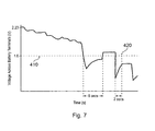
used. Fig. 7 is a graph showing terminal voltage against
time for a defective battery. The alert signal is
generated at point 420 when the instantaneous terminal
voltage (as detected by the voltage sensor 16) has
dropped below the threshold 410 for a total of 10
seconds. This 10 seconds is made up from 2 successive
drops below the threshold 410, the first lasting 8
seconds and the second lasting more than 2 seconds. The
alert signal is then sent to a display to light an LED
indicating that the battery is defective and/or liable to
fail. This LED is not shown in the accompanying drawings
illustrating the battery monitor display, but it can
easily be added as will be appreciated by a person
skilled in the art. In alternative embodiments the alert
signal could be used to generate a different visual
indication or even an audible alarm, so as to alert the
user to the battery's status. The processor detects that
the battery is no longer being charged (the end of a
charge event) when the terminal voltage drops below a
second predetermined threshold which is appreciably (e.g.
1%) below the maximum possible open circuit voltage of
the battery. In this embodiment the second predetermined
threshold is 2.2 V per cell. The first and second
predetermined thresholds are set depending on the maximum
possible open circuit voltage and the number of cells.
They are entered into the memory 30 of the battery
monitor when it is first set up. As will be clear to a
person skilled in the art, the maximum possible open
circuit voltage (both per cell and total) will depend on
the type of battery being monitored.
-
When the processor detects a discharge/charge cycle
event as described above it debits the life counter 35 by
subtracting a predetermined amount from the value held in
the life counter 35 to arrive at a new life counter value
35 reflecting the remaining life after the detected event
has occurred. The predetermined amount that is subtracted
is based on predetermined patterns of battery performance
taken from the manufacturer's specification for the
battery 5. However, not all discharge/charge cycles
result in equal degradation of the battery, therefore the
debited amount depends upon the characteristics of the
detected discharge/charge cycle.
-
The main factor that determines the amount of
degradation of each cycle is the depth of discharge. The
depth of discharge of the battery is a measure of how
much the battery was discharged during the discharge part
of the discharge/charge cycle. It can be expressed as
100% - the state of charge of the battery at the end of
the discharge part of the cycle. For example if the state
of charge at the end of the discharge part of the cycle
is 80% then the depth of discharge is 20%.
The relationship between the depth of discharge and
cycle life (i.e. number of cycles in the useful life of
the battery) for a particular type of Lead acid battery
is illustrated in Figure 4. Figure 4 is a graph in which
the x-axis represents the number of cycles and the y-axis
represents the percentage of capacity available (measured
from the battery state of charge after recharging)
compared to the capacity of the battery when it was new.
The line with crosses is where all the discharge cycles
are to 30% depth of discharge, the line with triangles
50% depth of discharge, the line with squares 75% depth
of discharge and the line with diamonds 100% depth of
discharge. It can be seen that greater depths of
discharge yield fewer cycles before the battery capacity
is significantly reduced. Thus, if the available battery
life is deemed to be up when the percentage of capacity
is reduced to 60% then there is a cycle life of less than
400 cycles if the depth of discharge of the cycles is
100%, but around 1500 cycles if the depth of discharge of
each cycle is only 30%.
-
Therefore the processor is configured to debit a
predetermined amount from the life counter based on the
measured depth of discharge of the detected
discharge/charge cycle and predetermined patterns of
battery performance such as those shown in Figure 4. The
depth of discharge of the discharge/charge cycle is
deemed to be the depth of discharge measured just before
the processing means 25 detected that the battery 5 was
being charged.
-
When a Lead acid battery is allowed to remain in a very
low state of charge the degradation of the electrode
plates is accelerated significantly, reducing life to a
period of weeks rather than years. Therefore another
event, which the processor 25 is configured to detect, is
when the battery 5 is in a state of very low charge such
that the battery performance will be permanently degraded
(e.g. due to irreversible deterioration of active
materials in the battery). The voltage level at which
this occurs may depend on the particular type of battery
being monitored. In the present embodiment the processor
is configured to detect that the battery is in a state of
'over discharge' which will damage the battery when the
voltage sensor measures a terminal voltage of less than
1.5V per cell of the battery (e.g. 9V if the battery has
six cells, the overall voltage or number of cells of the
battery being input into the memory 30 when the battery
monitor is first set up). The processor monitors the
amount of time which the battery 5 spends in this state
of over discharge and debits (subtracts) a predetermined
amount from the battery life counter 35 for each unit
time (e.g. each hour) that it detects that the battery 5
is in a state of over discharge.
-
A common means of operating Lead Acid batteries is to
attach them to a continuous DC electrical supply at a
fixed voltage that will just allow sufficient current to
flow into the fully charged battery to replace energy
lost by spontaneous self discharge reactions. This is
known as float charging. In this condition several
corrosive side reactions also occur that degrade the life
of the battery. Therefore, another event which the
processor 25 is configured to debit from the life counter
for, is when it detects that the battery is being
charged.
-
The processor 25 is configured to detect that the
monitored battery 5 is being charged as discussed above
(with reference to the discharge/charge cycle). However,
the debiting of life counter for charging of the battery
is in addition to and independent of the debiting of the
life counter each time a discharge/charge cycle is
detected. The debit for charging is per unit time spent
charging. The debit for a discharge/charge event is per
discharge/charge event, as detected by the start of a new
charging event.
-
The rate of degradation caused by charging is dependent
both on battery temperature and charging voltage. By
monitoring both these factors the device is able to
derive life degradation for the specific conditions. The
processor 25 records the time elapsed in the charging
mode and debits the life counter by a suitable
predetermined amount according to the specific conditions
for each unit time elapsed in this mode.
-
Because the combination of components within a Lead
acid battery are inherently thermodynamically unstable
all Lead acid batteries have a finite life even if they
are not subjected to periods of discharge and float
charge. The rate of degradation is temperature dependent
and by monitoring the amount of time elapsed during which
the battery 5 is neither in charge, nor discharge, nor
over-discharge mode the processor is able to debit the
life counter 35 at a suitable rate (i.e. by a suitable
predetermined amount per unit time the battery is idle
and in none of the above modes). The processor detects
that the battery 5 is idle when it detects that is in
equilibrium (it does this by monitoring the rate of
change of the voltage measured by the voltage sensor as
discussed above) and that it is not charging.
-
The state of charge measured by the state of charge
measuring apparatus 15 and the remaining available life
of the battery as indicated by the life counter 35 may be
stored in memory 30, they are displayed on a display of
the battery monitor or state of charge measuring
apparatus. The state of charge and available remaining
life may be displayed on separate displays or both on the
same display (either simultaneously or alternately by way
of a toggle switch or dependent on the detected mode of
operation of the battery). For example the battery
monitor can display the remaining available life when it
detects that the battery is charging and the state of
charge of the battery when the battery is not in a
charging mode.
-
The display may have simple coloured indicators (e.g.
green, amber, red lights or LEDs) to indicate the state
of charge or available life. Alternatively it may use
traditional analogue gauge representation, digitally
displayed values, or could communicate electronically via
a communication port and suitable protocol with an
external device.
-
In general the thresholds and predetermined debit
amounts discussed above may be set by reference to the
battery manufacturer's reference tables or empirical data
relating to the battery type with which the battery
monitor is to be used. However, if the battery is
defective or if it is used with fault equipment, then its
performance may not reflect the expected standard given
by this data. Therefore the processor 25 is configured
to send an alert signal when the instantaneous voltage,
detected by the monitor 10 across the terminals of the
battery 5, falls below a predetermined threshold for at
least a predetermined period of time. This threshold is
a low voltage, which a healthy battery would not normally
fall below. For example, 70% of the maximum possible
open circuit terminal voltage of the battery. In the
present embodiment, which is designed for a battery
having a maximum possible open terminal voltage of 2.23 V
per cell, this threshold is set at 1.6 V per cell. The
alert signal is generated by the processor 25 when the
total amount of time which the battery has spent with a
terminal voltage below this threshold is equal to or
greater than 10 seconds. Other embodiments will have a
different threshold or a different predetermined period
of time which must be exceeded in order to generate the
alert signal. The appropriate values will be determined
by the battery with which the battery monitor is to be
used. Fig. 7 is a graph showing terminal voltage against
time for a defective battery. The alert signal is
generated at point 420 when the instantaneous terminal
voltage (as detected by the voltage sensor 16) has
dropped below the threshold 410 for a total of 10
seconds. This 10 seconds is made up from 2 successive
drops below the threshold 410, the first lasting 8
seconds and the second lasting more than 2 seconds. The
alert signal is then sent to a display to light an LED
indicating that the battery is defective and/or liable to
fail. This LED is not shown in the accompanying drawings
illustrating the battery monitor display, but it can
easily be added as will be appreciated by a person
skilled in the art. In alternative embodiments the alert
signal could be used to generate a different visual
indication or even an audible alarm, so as to alert the
user to the battery's status.
-
One suitable display will now be described and is shown
in Figure 5. The display comprises a dual function
display based on an array of light emitting diodes
(LEDs). The display comprises 8 LEDs (although another
number may be used; for reasons of resolution the number
of LEDs will in most cases be a minimum of three and
maximum of eight). The LEDs are arranged in a row. The
first LED 105 is a green LED for showing full state of
charge or full battery life available, the next five LEDs
110 are also green and are used to indicate progressively
lower state of charge or lower amounts of remaining life.
The seventh LED 115 is amber and is used to indicate very
low state of charge or that the battery is close to the
end of its life. The final, eighth, LED 120 in the array
is red and is used to indicate a fully discharged battery
(i.e. close to or at 0% state of charge) or that the end
of the battery's useful life has been reached.
-
During discharge and open circuit periods (i.e. when
the battery is not charging) the flashing of a relevant
LED of the array indicates the state of charge. The
duration, frequency and intensity the LED flashes may be
chosen to limit discharge of the monitored battery to an
acceptable level above the normal self discharge of the
open circuit battery. During charging, when electrical
supply is effectively unlimited, the LED array can be
used to illuminate a relevant LED to indicate the state
of life of the battery.
One or more of the LED units can also be used to
transmit data concerning the battery 5 collected by the
battery monitor 1 to a decoder and/or storage device
where detailed information collated during the life of
the battery can be analyzed further.
-
The dual information display for State of Life and
State of Charge can be used to estimate the capability to
perform particular discharge duties as the battery
deteriorates towards the end of life. For example the
State of Charge display may indicate that a particular
duty cycle results in 90-100% depth of discharge of the
battery. In this case it will not be possible perform
this duty cycle for the full life duration indicated by
the LED array. This is because the performance of the
battery will fall below the initial level as indicated in
Figure 4. In contrast a duty cycle resulting in only 50-60%
depth of discharge will be supportable throughout the
life indicated by the LED array.
-
This type of interaction between State of Charge and
State of life (as represented by the life counter 35) is
particularly useful where variable duty cycles are
experienced in the battery application. For example where
a battery is used to supply an electrically powered wheel
chair, the available driving range will start to decrease
before the battery becomes completely unserviceable. If
the user only travels short distances a decision can be
made delay replacement, but if a change to longer ranges
is anticipated a decision can be made to purchase a new
battery.
-
The functions of measurement, data processing and
display may be carried out by way of a continuously
recurring software routine embedded in the processing
means 25. Figure 6 shows the operation of one suitable
software routine. As will be apparent to a person
skilled in the art, other routines would be possible. It
would also be possible to have the software routine
embedded on a custom made chip.
-
The routine starts in step 200 and progresses to
step 210 where the processor 25 reads the ambient
temperature detected by the temperature sensor 20 of the
monitor 10. The processor 25 then reads the voltage
across the battery's terminals as measured by the voltage
sensor 16 and the rate of change of the voltage as
measured by the rate of change measurer 40 of the state
of charge measuring apparatus 15 in step 220. The
processor than proceeds to step 230 in which it
determines whether or not the battery 5 is being charged.
It determines that the battery 5 is being charged when
the rate of change of the sensed terminal voltage is
below a predetermined level and the measured terminal
voltage is above a predetermined level corresponding to
the maximum possible open circuit terminal voltage for
the battery 5. These predetermined levels are set when
the battery monitor is initialised and depend on the
characteristics of the battery with which it is to be
used. For the battery in the present embodiment, 1.5 mV
volts per minute per battery cell is a suitable
predetermined threshold level for the voltage rate of
change and the maximum possible open circuit voltage of
the battery 5 is 2.23 V per cell of the battery.
-
If at step 230 the processor 25 determines that the
battery 5 is being charged (on charge) then it progresses
to step 240 where the life counter is debited
(decremented) according to the depth of the last
discharge (as described above) which is stored in memory
30 and according to the average values of the detected
temperature. In other words a predetermined amount
corresponding to the detected discharge/charge cycle is
subtracted from the value of the life counter 35. The
new life counter value is broadcast in an information
data stream to the display 200 in step 250 so that the
appropriate LED is lit according to the remaining
percentage of the battery's useful life as indicated by
the life counter value, in step 260.
-
The processor 25 then progresses to step 270 in
which it updates the memory 30 to record the total amount
of time that the battery 5 has spent respectively in the
charge state, discharge state and the equilibrium state.
This information can be read from the memory 30 and a
processor 25 or output to an external unit as described
below. The processor 25 then progresses from step 270
back to the start 100 of the program and the program
cycle is repeated.
-
If at step 230 the processor 25 determines that the
battery 5 is not being charged, then it progresses to
step 280 in which it determines whether or not the
battery 5 is in a state of equilibrium. The processor 25
determines that the battery is in a state of equilibrium
if the rate of change of the measured battery terminal
voltage is below a predetermined level as discussed
above. If the processor 25 determines that the battery
is in a state of equilibrium then it calculates the state
of charge of the battery (and the corresponding depth of
discharge) on the basis of the measured steady terminal
voltage and with a correction according to the ambient
temperature measured in step 210. The processor carries
out these calculations in step 290 of the program and
updates the depth of discharge of the battery in memory
30 and also the minimum recorded voltage of the battery
if the current measured terminal voltage is less than the
previous lowest recorded terminal voltage.
-
After step 290 the processor progresses to step 300
in which it outputs the measured state of charge of the
battery 5 to the display unit 100. The appropriate LED
is lit according to the measured state of charge
(expressed as a percentage). If the processor at step
280 determines that the battery 5 is not in equilibrium
then the measured state of charge and depth of discharge
of the battery are not updated and the processor proceeds
directly to step 300 in which it displays the measured
state of charge of the battery (which has not been
updated). From step 300 the processor 25 proceeds to
step 270 in which the total amount of time which the
battery has spent in charge, discharge and equilibrium
states is updated in the memory 30. The processor 25
then proceeds from step 270 back to the start of the
program cycle as described above.
-
Another aspect of the battery monitor 1 is its data
storage function, which allows the device to capture and
record significant operational data relating to the
battery and its environment. This information can be
transmitted to an external reading device, preferably by
a non-contacting method, to allow more detailed analysis
of the service history of a battery. This can be used to
investigate failure modes and assess the effects of
design enhancements as part of continuous improvement
activities. It can also be used as an integral part of a
battery management system where information about each
section of an electrical system can be co-ordinated to
provide enhanced performance or life.
-
The type of information that can be logged for
future display includes Charge cycle number, total
charging time, total rest time, total discharge time,
over-discharge time, mean depth of discharge, total
operating time, maximum charging temperature, mean
charging temperature, minimum voltage experienced and
calculated remaining life account.
-
A preferred method for the communication of data is
to utilise at least one of the LED components included in
the array used to indicate the State of Charge and State
of Life conditions. This LED is controlled by the
processing chip of the device to switch on and off
according to a standard digital communication code (e.g.
RS485). This signal is received and decoded by an optical
device for display and storage. For example an embodiment
of the device uses the LED that indicates the final
segment of life, which is conveniently coloured red, as
the transmitting component. The meter transmits data at
intervals while the battery is in charging mode, in
alternation with display of the state of life of the
battery.