EP1481702B1 - Breathing assistance apparatus - Google Patents
Breathing assistance apparatus Download PDFInfo
- Publication number
- EP1481702B1 EP1481702B1 EP04012752A EP04012752A EP1481702B1 EP 1481702 B1 EP1481702 B1 EP 1481702B1 EP 04012752 A EP04012752 A EP 04012752A EP 04012752 A EP04012752 A EP 04012752A EP 1481702 B1 EP1481702 B1 EP 1481702B1
- Authority
- EP
- European Patent Office
- Prior art keywords
- nasal cannula
- gases
- cannula assembly
- patient
- nasal
- Prior art date
- Legal status (The legal status is an assumption and is not a legal conclusion. Google has not performed a legal analysis and makes no representation as to the accuracy of the status listed.)
- Active
Links
Images


Classifications
-
- A—HUMAN NECESSITIES
- A61—MEDICAL OR VETERINARY SCIENCE; HYGIENE
- A61M—DEVICES FOR INTRODUCING MEDIA INTO, OR ONTO, THE BODY; DEVICES FOR TRANSDUCING BODY MEDIA OR FOR TAKING MEDIA FROM THE BODY; DEVICES FOR PRODUCING OR ENDING SLEEP OR STUPOR
- A61M16/00—Devices for influencing the respiratory system of patients by gas treatment, e.g. mouth-to-mouth respiration; Tracheal tubes
- A61M16/08—Bellows; Connecting tubes ; Water traps; Patient circuits
- A61M16/0875—Connecting tubes
-
- A—HUMAN NECESSITIES
- A61—MEDICAL OR VETERINARY SCIENCE; HYGIENE
- A61M—DEVICES FOR INTRODUCING MEDIA INTO, OR ONTO, THE BODY; DEVICES FOR TRANSDUCING BODY MEDIA OR FOR TAKING MEDIA FROM THE BODY; DEVICES FOR PRODUCING OR ENDING SLEEP OR STUPOR
- A61M16/00—Devices for influencing the respiratory system of patients by gas treatment, e.g. mouth-to-mouth respiration; Tracheal tubes
- A61M16/0003—Accessories therefor, e.g. sensors, vibrators, negative pressure
-
- A—HUMAN NECESSITIES
- A61—MEDICAL OR VETERINARY SCIENCE; HYGIENE
- A61M—DEVICES FOR INTRODUCING MEDIA INTO, OR ONTO, THE BODY; DEVICES FOR TRANSDUCING BODY MEDIA OR FOR TAKING MEDIA FROM THE BODY; DEVICES FOR PRODUCING OR ENDING SLEEP OR STUPOR
- A61M16/00—Devices for influencing the respiratory system of patients by gas treatment, e.g. mouth-to-mouth respiration; Tracheal tubes
- A61M16/0057—Pumps therefor
- A61M16/0066—Blowers or centrifugal pumps
-
- A—HUMAN NECESSITIES
- A61—MEDICAL OR VETERINARY SCIENCE; HYGIENE
- A61M—DEVICES FOR INTRODUCING MEDIA INTO, OR ONTO, THE BODY; DEVICES FOR TRANSDUCING BODY MEDIA OR FOR TAKING MEDIA FROM THE BODY; DEVICES FOR PRODUCING OR ENDING SLEEP OR STUPOR
- A61M16/00—Devices for influencing the respiratory system of patients by gas treatment, e.g. mouth-to-mouth respiration; Tracheal tubes
- A61M16/021—Devices for influencing the respiratory system of patients by gas treatment, e.g. mouth-to-mouth respiration; Tracheal tubes operated by electrical means
- A61M16/022—Control means therefor
- A61M16/024—Control means therefor including calculation means, e.g. using a processor
-
- A—HUMAN NECESSITIES
- A61—MEDICAL OR VETERINARY SCIENCE; HYGIENE
- A61M—DEVICES FOR INTRODUCING MEDIA INTO, OR ONTO, THE BODY; DEVICES FOR TRANSDUCING BODY MEDIA OR FOR TAKING MEDIA FROM THE BODY; DEVICES FOR PRODUCING OR ENDING SLEEP OR STUPOR
- A61M16/00—Devices for influencing the respiratory system of patients by gas treatment, e.g. mouth-to-mouth respiration; Tracheal tubes
- A61M16/04—Tracheal tubes
- A61M16/0402—Special features for tracheal tubes not otherwise provided for
- A61M16/0415—Special features for tracheal tubes not otherwise provided for with access means to the stomach
-
- A—HUMAN NECESSITIES
- A61—MEDICAL OR VETERINARY SCIENCE; HYGIENE
- A61M—DEVICES FOR INTRODUCING MEDIA INTO, OR ONTO, THE BODY; DEVICES FOR TRANSDUCING BODY MEDIA OR FOR TAKING MEDIA FROM THE BODY; DEVICES FOR PRODUCING OR ENDING SLEEP OR STUPOR
- A61M16/00—Devices for influencing the respiratory system of patients by gas treatment, e.g. mouth-to-mouth respiration; Tracheal tubes
- A61M16/06—Respiratory or anaesthetic masks
- A61M16/0605—Means for improving the adaptation of the mask to the patient
- A61M16/0616—Means for improving the adaptation of the mask to the patient with face sealing means comprising a flap or membrane projecting inwards, such that sealing increases with increasing inhalation gas pressure
- A61M16/0622—Means for improving the adaptation of the mask to the patient with face sealing means comprising a flap or membrane projecting inwards, such that sealing increases with increasing inhalation gas pressure having an underlying cushion
-
- A—HUMAN NECESSITIES
- A61—MEDICAL OR VETERINARY SCIENCE; HYGIENE
- A61M—DEVICES FOR INTRODUCING MEDIA INTO, OR ONTO, THE BODY; DEVICES FOR TRANSDUCING BODY MEDIA OR FOR TAKING MEDIA FROM THE BODY; DEVICES FOR PRODUCING OR ENDING SLEEP OR STUPOR
- A61M16/00—Devices for influencing the respiratory system of patients by gas treatment, e.g. mouth-to-mouth respiration; Tracheal tubes
- A61M16/06—Respiratory or anaesthetic masks
- A61M16/0666—Nasal cannulas or tubing
- A61M16/0672—Nasal cannula assemblies for oxygen therapy
-
- A—HUMAN NECESSITIES
- A61—MEDICAL OR VETERINARY SCIENCE; HYGIENE
- A61M—DEVICES FOR INTRODUCING MEDIA INTO, OR ONTO, THE BODY; DEVICES FOR TRANSDUCING BODY MEDIA OR FOR TAKING MEDIA FROM THE BODY; DEVICES FOR PRODUCING OR ENDING SLEEP OR STUPOR
- A61M16/00—Devices for influencing the respiratory system of patients by gas treatment, e.g. mouth-to-mouth respiration; Tracheal tubes
- A61M16/06—Respiratory or anaesthetic masks
- A61M16/0683—Holding devices therefor
- A61M16/0688—Holding devices therefor by means of an adhesive
-
- A—HUMAN NECESSITIES
- A61—MEDICAL OR VETERINARY SCIENCE; HYGIENE
- A61M—DEVICES FOR INTRODUCING MEDIA INTO, OR ONTO, THE BODY; DEVICES FOR TRANSDUCING BODY MEDIA OR FOR TAKING MEDIA FROM THE BODY; DEVICES FOR PRODUCING OR ENDING SLEEP OR STUPOR
- A61M16/00—Devices for influencing the respiratory system of patients by gas treatment, e.g. mouth-to-mouth respiration; Tracheal tubes
- A61M16/08—Bellows; Connecting tubes ; Water traps; Patient circuits
- A61M16/0816—Joints or connectors
-
- A—HUMAN NECESSITIES
- A61—MEDICAL OR VETERINARY SCIENCE; HYGIENE
- A61M—DEVICES FOR INTRODUCING MEDIA INTO, OR ONTO, THE BODY; DEVICES FOR TRANSDUCING BODY MEDIA OR FOR TAKING MEDIA FROM THE BODY; DEVICES FOR PRODUCING OR ENDING SLEEP OR STUPOR
- A61M16/00—Devices for influencing the respiratory system of patients by gas treatment, e.g. mouth-to-mouth respiration; Tracheal tubes
- A61M16/10—Preparation of respiratory gases or vapours
- A61M16/1075—Preparation of respiratory gases or vapours by influencing the temperature
- A61M16/109—Preparation of respiratory gases or vapours by influencing the temperature the humidifying liquid or the beneficial agent
-
- A—HUMAN NECESSITIES
- A61—MEDICAL OR VETERINARY SCIENCE; HYGIENE
- A61M—DEVICES FOR INTRODUCING MEDIA INTO, OR ONTO, THE BODY; DEVICES FOR TRANSDUCING BODY MEDIA OR FOR TAKING MEDIA FROM THE BODY; DEVICES FOR PRODUCING OR ENDING SLEEP OR STUPOR
- A61M16/00—Devices for influencing the respiratory system of patients by gas treatment, e.g. mouth-to-mouth respiration; Tracheal tubes
- A61M16/10—Preparation of respiratory gases or vapours
- A61M16/1075—Preparation of respiratory gases or vapours by influencing the temperature
- A61M16/1095—Preparation of respiratory gases or vapours by influencing the temperature in the connecting tubes
-
- A—HUMAN NECESSITIES
- A61—MEDICAL OR VETERINARY SCIENCE; HYGIENE
- A61M—DEVICES FOR INTRODUCING MEDIA INTO, OR ONTO, THE BODY; DEVICES FOR TRANSDUCING BODY MEDIA OR FOR TAKING MEDIA FROM THE BODY; DEVICES FOR PRODUCING OR ENDING SLEEP OR STUPOR
- A61M16/00—Devices for influencing the respiratory system of patients by gas treatment, e.g. mouth-to-mouth respiration; Tracheal tubes
- A61M16/10—Preparation of respiratory gases or vapours
- A61M16/14—Preparation of respiratory gases or vapours by mixing different fluids, one of them being in a liquid phase
- A61M16/16—Devices to humidify the respiration air
-
- A—HUMAN NECESSITIES
- A61—MEDICAL OR VETERINARY SCIENCE; HYGIENE
- A61M—DEVICES FOR INTRODUCING MEDIA INTO, OR ONTO, THE BODY; DEVICES FOR TRANSDUCING BODY MEDIA OR FOR TAKING MEDIA FROM THE BODY; DEVICES FOR PRODUCING OR ENDING SLEEP OR STUPOR
- A61M16/00—Devices for influencing the respiratory system of patients by gas treatment, e.g. mouth-to-mouth respiration; Tracheal tubes
- A61M16/0003—Accessories therefor, e.g. sensors, vibrators, negative pressure
- A61M2016/003—Accessories therefor, e.g. sensors, vibrators, negative pressure with a flowmeter
-
- A—HUMAN NECESSITIES
- A61—MEDICAL OR VETERINARY SCIENCE; HYGIENE
- A61M—DEVICES FOR INTRODUCING MEDIA INTO, OR ONTO, THE BODY; DEVICES FOR TRANSDUCING BODY MEDIA OR FOR TAKING MEDIA FROM THE BODY; DEVICES FOR PRODUCING OR ENDING SLEEP OR STUPOR
- A61M2202/00—Special media to be introduced, removed or treated
- A61M2202/02—Gases
- A61M2202/0208—Oxygen
-
- A—HUMAN NECESSITIES
- A61—MEDICAL OR VETERINARY SCIENCE; HYGIENE
- A61M—DEVICES FOR INTRODUCING MEDIA INTO, OR ONTO, THE BODY; DEVICES FOR TRANSDUCING BODY MEDIA OR FOR TAKING MEDIA FROM THE BODY; DEVICES FOR PRODUCING OR ENDING SLEEP OR STUPOR
- A61M2205/00—General characteristics of the apparatus
- A61M2205/33—Controlling, regulating or measuring
- A61M2205/3331—Pressure; Flow
- A61M2205/3334—Measuring or controlling the flow rate
-
- A—HUMAN NECESSITIES
- A61—MEDICAL OR VETERINARY SCIENCE; HYGIENE
- A61M—DEVICES FOR INTRODUCING MEDIA INTO, OR ONTO, THE BODY; DEVICES FOR TRANSDUCING BODY MEDIA OR FOR TAKING MEDIA FROM THE BODY; DEVICES FOR PRODUCING OR ENDING SLEEP OR STUPOR
- A61M2205/00—General characteristics of the apparatus
- A61M2205/33—Controlling, regulating or measuring
- A61M2205/3368—Temperature
-
- A—HUMAN NECESSITIES
- A61—MEDICAL OR VETERINARY SCIENCE; HYGIENE
- A61M—DEVICES FOR INTRODUCING MEDIA INTO, OR ONTO, THE BODY; DEVICES FOR TRANSDUCING BODY MEDIA OR FOR TAKING MEDIA FROM THE BODY; DEVICES FOR PRODUCING OR ENDING SLEEP OR STUPOR
- A61M2205/00—General characteristics of the apparatus
- A61M2205/50—General characteristics of the apparatus with microprocessors or computers
- A61M2205/52—General characteristics of the apparatus with microprocessors or computers with memories providing a history of measured variating parameters of apparatus or patient
Definitions
- the present invention relates particularly, though not solely, to the delivery of high flow humidified pressurised oxygen and/or air to a patient in need of respiratory support by way of a nasal cannula.
- Nasal cannula assemblies generally consist of entry tubing, either symmetric or single sided that lies across the upper lip. Protruding from this tubing are open ended prongs which extend into the nares of the patient to deliver oxygen.
- a symmetrical nasal cannula assembly which has a face mounted part that includes a pair of prongs and a detachable manifold part which in use is connected to a gases supply, is described in DE 28036 .
- Nasal cannulae have the advantage of being more comfortable and acceptable than a face mask to most patients.
- the existing market for nasal cannula is well serviced by devices suitable for the delivery of gases in the 0 to 5 litre per minute range. These devices are typically supplied by a double entry lumen of small diameter (2-3mm range) that supplies both sides of the nasal cannula and provides even airflow to each nasal prong. These devices work well for the delivery of low humidity gas flows of between 0 to 5 litre per minute and have been well received by patients over the last 30 years.
- a nasal cannula that is disclosed in US2,868,199 that consists of a single flow entry nasal cannula.
- This single flow entry has the advantage of being unobtrusive, and more relevant to delivering humidity than a dual flow entry style of nasal cannula, simply due to the advantage of flow rates and surface area for heat loss.
- the single flow entry is on the left side only, which causes the user difficulty in use if the flow source is on the opposite side of the user requiring longer lengths of tubing and causing the tube to cross the body.
- the cannula itself is manufactured as one part only, of PVC plastic. This product is not designed for delivering high flow or high humidity gases.
- the nasal prongs are less than 3mm in diameter resulting in noise and high velocity jetting of gas causing severe irritation at high flows. These cannulae are difficult to clean inside, are uncomfortable, and the prongs are too rigid for extended therapies.
- US3,754,552 of Sandoz-Wander, Inc discloses a nasal cannula, having two nasal prongs, adapted for the intake of therapeutic gas from either the right or left side of the patient.
- the nasal cannula has a bore within it that feeds each prong. The bore is able to receive a tube for supplying gases to the cannula in either end and in use a plug is required to obstruct the unused end.
- the NASALAIRETM manufactures a nasal cannula device called the NASALAIRETM.
- This nasal cannula is a dual flow entry style cannula where two large tubes come from behind the ears, through the field of vision to the upper lip. In this device air or oxygen travels down a wide bore conduit to the nasal cannula.
- the NASALAIRETM creates a physical seal between the nares and itself, and relies on the absence of leaks around itself and the nares to deliver pressure supplied by a continuous positive airway pressure (CPAP) blower to the airway of the wearer. The wearer is required to breathe in and out of the NASALAIRETM, thereby rebreathing some of the exhaled air from the lungs.
- CPAP continuous positive airway pressure
- the NASALAIRETM is not designed to deliver humidified gases to the patient, being unheated and without insulation of any type.
- the NASALAIRETM cannula is uncomfortable especially if a patient rests on the tube, as would happen during sleep, and is also obtrusive.
- cannulae are made from soft polymeric material (for example, silicone) that absorbs heat and does not breathe and therefore sweat is generated under the contact points with the skin.
- soft polymeric material for example, silicone
- This heat in combination with the polymeric materials waterproof properties results in sweat being trapped against a patient's skin and the patient has the sensation of overheating. The trapped sweat is uncomfortable and could lead to rashes.
- Oxygen is generally supplied as a dry gas, but it is well known in the art to either heat and/or humidify gases before delivering them for breathing by a patient. In particular when delivering oxygen, or an oxygen air mixture, it has proven beneficial to humidify the gases first.
- WO 01/41854 of Vapotherm, Inc. a system is disclosed that allows the delivery of humidified oxygen through a nasal cannula. This system uses a narrow bore conduit and nasal cannula with a high resistance to gas flows, thereby requiring the oxygen be of a high pressure. Air, as well as oxygen, can also be passed down the conduit and nasal cannula and it too must be of a high pressure.
- This system allows the delivery of high flows of oxygen enriched air to the patient, but is limited in the flows achievable due to the narrow bore of the cannula resulting in high resistance gas flow and excessive velocity and noise upon exiting the cannula. Furthermore, the narrowness of the nasal cannula in this system allows the patient to easily expire gases from their nostrils as there is a reasonable gap between the prongs and the patient's nares. Thus positive airway pressure is not created and as such this cannula is not suitable for the treatment of Obstructive Sleep Apnea (OSA).
- OSA Obstructive Sleep Apnea
- a heated breathing circuit or tube delivering heated and humidified gases to the patient, followed by a short length of non-heated tube close to the patient.
- This unheated tube may be a short unheated extension tube or catheter mount.
- the unheated section of tube is usually intended to be very flexible to reduce torsion or pulling on the patient interface, to allow the gases to cool slightly towards the dew point of the gas, and also to eliminate hot surface temperatures near the patient.
- a nasal cannula assembly according to claim 1.
- the nasal cannula assembly of the present invention will generally have associated three main pieces of apparatus. Firstly an active humidifier that controls the temperature of a heater plate heating a body of water to achieve a desired temperature and humidity of the gases being humidified. Secondly a transport conduit from the humidifier to the patient is also required, which is preferably heated to reduce condensation, or "rain out”. Thirdly a nasal cannula designed to fit into the nasal cavity of a patient or user and deliver humidified, pressurized gases.
- FIG. 1 a humidifying circuit as might be used with the nasal cannula of the present invention is shown.
- a patient 1 is receiving humidified and pressurised gases through a nasal cannula assembly 20 connected to a humidified gases transportation pathway or inspiratory conduit 3 that in turn is connected to a humidifier 8 (including humidification chamber 5) that is supplied with gases from a blower 15 or other appropriate gases supply means.
- the inspiratory conduit 3 is connected to the outlet 4 of a humidification chamber 5 which contains a volume of water 6.
- Humidification chamber 5 is preferably formed from a plastics material and may have a highly heat conductive base (for example an aluminium base) which is in direct contact with a heater plate 7 of humidifier 8.
- the humidifier 8 is provided with control means or electronic controller 9 which may comprise a microprocessor based controller executing computer software commands stored in associated memory. Gases flowing through the inspiratory conduit 3 are passed to the patient by way of the nasal cannula 20.
- Controller 9 receives input from sources such as user input means or dial 10 through which a user of the device may, for example, set a predetermined required value (preset value) of humidity or temperature of the gases supplied to patient 1.
- a user of the device may, for example, set a predetermined required value (preset value) of humidity or temperature of the gases supplied to patient 1.
- controller 9 determines when (or to what level) to energise heater plate 7 to heat the water 6 within humidification chamber 5.
- the blower 15 may be provided with a variable speed pump or fan 2 which draws air or other gases through the blower inlet 17.
- the speed of variable speed pump or fan 2 may be controlled by a further control means or electronic controller 18 (or alternatively the function of this controller 18 could be carried out by the other controller 9) in response to inputs from controller 9 and a user set predetermined required value (preset value) of pressure or fan speed via dial 19.
- a heating element 11 may be provided within the conduit or tubing 3 to help prevent condensation of the humidified gases within the conduit. Such condensation is due to the temperature of the walls of the conduit being close to the ambient temperature, (being the temperature of the surrounding atmosphere) which is usually lower than the temperature of the humidified gases within the conduit.
- the heater element is effectively replaces the energy lost from the gases through conduction and convection during transit through the conduit. Thus the conduit heater element ensures the gases delivered are at an optimal temperature and humidity.
- the nasal cannula assembly of the present invention provides a patient with a patient interface suitable for the delivery of high airflow, high humidity gas flow to the patient's nasal cavity.
- a particular aspect of the nasal cannula of the present invention is the suitability for long term therapy where the patient, for example, a patient suffering from Chronic Obstructive Pulmonary Disease (COPD), will wear the cannula for several hours per day over weeks, months and in some cases years. Therefore, for patient's to accept use of nasal cannula under these circumstances the cannula need to be unobtrusive, comfortable to wear, noise free, suitable for wearing while sleeping, easy to clean and have prongs that can generate Positive End Expiry Pressure (PEEP).
- PEEP Positive End Expiry Pressure
- the cannula of the present invention may also be used for other therapies such as for Continuous Positive Airway Pressure (CPAP) therapy and the like.
- CPAP Continuous Positive Airway Pressure
- FIG. 2 A first form of the nasal cannula assembly of the present invention is shown in Figures 2 and 3 .
- This nasal cannula assembly generally indicated as 20, comprises a face mount part 21 including a pair of tubular nasal prongs 22, 23 integrally molded with or removably attached to the face mount part 21, and a gases flow manifold part 24 that is integrally molded with or attached to tubing 3, such as that described above.
- the face mount part 21 and prongs 22, 23 are preferably moulded from silicone or other flexible material as is known is the art of cannula construction.
- the gases flow manifold part 24 is preferably made from a hard plastics material, although it may be manufactured in other suitable materials.
- the face mount part 21 is preferably integrally molded with the prongs 22, 23 and is shaped to generally follow the contours of a patient's face around the upper lip area.
- the inner side (not shown) of the face mount part 21 may be provided with a breathable pad, to be described below.
- the outer side 25 of the face mount part 21 has moulded in it an elongated oval recess 26 and two oval recesses 27, 28 that extend through the face mount part 21 and each meet the tubular passageway's formed within each of the tubular prongs 22, 23.
- the gases flow manifold part 24 is generally tubular in shape having a substantially circular inlet (not shown) on one side that curves around to an elongated oval outlet 29.
- the circular inlet receives the end of the conduit or tubing 3, so that gases are supplied to the gases flow manifold part 24 and are able to flow through the inlet and out the outlet 29.
- the tubing 3 is preferably permanently fixed to the manifold part 24, but may be releasably attachable.
- the face mount part 21 is flexible and the manifold part 24 made from a harder plastics material it is possible for the manifold part outlet 29 to be easily pushed or forced into the elongated recess 26.
- the face mount part elongate recess 26 and manifold part outlet 29 are symmetrical in shape and configuration and therefore the manifold part 24 is capable of being switched or flipped such that the tubing 3 extends from either the left or right side of the patient's nares.
- the nasal cannula assembly of the present invention is more comfortable to wear as it sits under the septum of the nose and supports the two nasal prongs.
- the prongs are made in one moulding of a soft material such as silicone the prongs are easy to insert in the patient's nares and comfortable to the patient.
- a nasal cannula assembly For a nasal cannula assembly to be suitable for wearing during sleep each night the cannula must be noise free. Many prior art cannulas are prone to whistling. With a range of airflows generally being between 0 to 40 litres per minute, although airflows of 60 litres per minute are envisaged for the present nasal cannula, and with the air or gases being supplied to a single horizontal entry point it has proved difficult to prevent whistling. For this reason the face mount part 21 is contoured such that the pressure distribution within the face mount part 21 forces even airflows up each nasal prong.
- the cannula assembly of the present invention As the nasal cannula assembly of the present invention is likely to be used while a patient is sleeping, the cannula must be easily tailored for the patients sleeping arrangement.
- the cannula of the present invention supplies high flow humidified gases to the patient from either the left side or the right side of the cannula thus allowing the minimum length connection circuit to the bedside unit supplying the humidified gas.
- the nasal cannula assembly of the present invention allows for the horizontal entry of gases from either side the patient can configure the unit as left or right entry for their particular sleeping arrangement. It is envisaged that the tubing 3 is approximately two meters in length to allow for added flexibility of the cannula.
- the nasal cannula assembly 30 is of a substantially similar form to the first form described above in relation to Figures 2 and 3 , and has a face mount part 32, a pair of nasal prongs 33, 34, gases flow manifold part 35 and tubing 3.
- the face mount part 32 and pair of nasal prongs 33, 34 are preferably integrally molded as one piece from a soft plastics material such as silicone, although in other forms the face mount part and prongs may be separate, but capable of attachment together for use.
- the nasal prongs 33, 34 are tubular in shape and may be consistent in diameter but may be shaped to fit the contours of the human nares.
- a strap or strap attachment means 31 may be integrally formed or attached to the face mount part 32 in order to enable the nasal cannula assembly 30 to be held in place about a patient's face.
- the face mount part 32 has an open tubular recess 38 extending below the nasal prongs 33, 34 that is capable of receiving a gases flow manifold part 35 that is attached to or integrally formed with tubing 3.
- the tubular passageways within the nasal prongs 33, 34 extend through the face mount part and into the recess 38.
- the gases flow manifold part 35 is blocked at one end 39 but attached to the tubing at the other end and has an elongate opening 37 that acts as an exit for gases received from the tubing 3.
- the face mount part 32 Due to the flexible nature of the material the face mount part 32 is made from, and as the gases flow manifold part 35 is made from a hard plastics material, the gases flow manifold part 35 can be pushed through the tubular recess 38 in the face mount part 32 and the elongate opening 37 in the gases flow manifold part 35 meets with the tubular passageways of the prongs 33, 34. Therefore, in use, gases flowing through the tubing and into the gases flow manifold part 35 exit through the opening 37 and into the tubular passageways in the prongs 33, 34, then into the patient's nares.
- the manifold part 35 is provided with an inner recessed portion 60 and contoured lip areas 58, 59.
- the tubular body forming the recess 38 sits within the inner recessed portion 60 and the edges of the tubular body abut the lips 58, 59 formed on the manifold part 35.
- a breathable pad may be supplied with any of the nasal cannula assemblies described above.
- a pad 36 is shown in Figure 7 in the second form of the nasal cannula assembly as described above. It must be appreciated that a pad of this type may be provided with any of the other two forms as herein described.
- the pad is preferably attached to the inside surface of the face mount part 32 that connects with the upper lip of the patient wearing the cannula.
- the pad 36 which is preferably made from an absorbent cloth, reduces the incidence of heat and moisture on the patient's upper lip, where the face mount part 32 sits against their face.
- the pad 36 is preferably attached to the face mount part 32 by adhesive, for example, the pad could be supplied with a sticky backing that adheres to the face mount part, so that the pad can be easily removed from the face mount part and replaced as necessary.
- the pad reduces the effects of heat against the patient's skin and improves hygiene, as any contaminants or cultures that may grow close to the patient's skin, in the warm environment can be removed on removal and replacement of the pad.
- FIG. 8 to 11 a third form of the nasal cannula assembly of the present invention is shown where the nasal cannula assembly comprises three parts.
- a gases flow manifold part 40 is shown in Figure 8 which is designed for either left or right hand orientation and provides a symmetrical flow to a pair of nasal cannula assembly prongs 41, 42 (see Figures 10 or 11 ).
- a pair of soft nasal prongs 41 or 42 are provided that are capable of being attached to the top of the gases flow manifold part 40 allowing for a large range of different shaped and spaced prongs to be available to the patient.
- Two such configurations of prongs 41, 42 are shown in Figures 10 and 11 .
- the prongs 41 of Figure 10 are narrow elongate tubular members 43, 44 of a substantially constant diameter that are fittable into a patient's nares.
- the prongs are integrally molded with a body 45 that is fittable with the gases flow manifold part 40 (see Figure 8 ) by appropriate means, for example, friction or snap fit.
- the prongs 42 of Figure 11 are tapered tubular members 46, 47 moulded to a body 48. Again, this body 48 is capable of being fitted (friction, snap or other) to the gases flow manifold part of Figure 8 .
- These prongs are preferably made from a soft plastics material such as silicon, although other suitable materials
- prongs With the prongs being removable they are easily cleaned and could also be disinfected for second or subsequent use.
- the third part to the third form of the nasal cannula assembly shown in Figures 8 to 11 is the face mount part 49 of Figure 9 .
- the face mount part 49 comprises a head strap 53 attached to a pad 50, that may be a moulded or shaped substantially rigid pad, for example, made from a plastics material such as polypropylene.
- the pad 36 may include a breathable cloth pad on its surface that abuts a patient's face, similar to that pad 36 described in relation to Figure 7 , or the head straps 53 may extend to sit behind the pad.
- the head strap 53 is preferably made from a flexible material, such as neoprene.
- the plastic pad 50 is shown in Figure 9 and has a plurality of apertures 61 formed into to allow for heat and moisture to dissipate from the patient's facial surface.
- the pad 50 has fastening means 51, 52 for holding the gases flow manifold part 49 in the correct position on the upper lip of the patient.
- the fastening means may be clips 51, 52 that are fittable into complimentary recesses 54, 55, 56, 57 provided in or on the manifold part 40 (see Figure 8 ), but other appropriate fastening means may be provided with the cannula.
- fastening means is a loop that is integrally moulded as part of the prongs which wraps around the face mount part and latches over a protrusion on the manifold part thus encapsulating the face mount part and holding the assembly together stably and securely.
- a fastening means is a plastic VelcroTM type attachment where one side would attach to one side of the manifold part 40 and the other side to the plastic pad 50.
- at least one recess must be provided on either side of the manifold 40.
- two recesses 54, 55 are provided on one side of the manifold 40 and two other recesses 56, 57 on the other side of the manifold 40.
- the attachment between the face mount part 49 and the manifold part 40 allows for either left or right hand orientation of the manifold part and associated tubing.
- the cannula of the present invention will be reusable for several wearings on a single patient and as such the nasal cannula assembly must be hygienic. It is envisaged that all the embodiments of the nasal cannula assembly of the present invention as herein described can be disassembled so that the cannula is easier to clean.
- the prongs and integrally attached parts are capable of being stored in a sterile solution until reused, much like false teeth are currently stored while not in use.
- detachable nasal cannula assembly described in relation to Figures 8 to 11 allows a patient on long-term therapy to order their particular prong size but maintain a common tubing connection system right to the point of connection into the manifold under the nose.
- tubing can be provided that has vapour transmission properties.
- the nasal cannula of the present invention (in particular, that of the second form described herein) may be provided with a short piece of breathable tubing 62 between the nasal cannula 30 and heated tubing 3.
- the tubing 62 is preferably made from a material that allows for transmission of water, such as a hydrophilic material, for example SYMPATEXTM.
- Test results show the performance of a 420mm length of breathable tube, operating with air input at an absolute humidity of 42.2 mg/L, an airflow of 10 litres per minute, in a room with ambient air at 22 degrees C and 50% RH, only lowered the air temperature to 37 and the absolute humidity to 41.15 mg/L at the exit of the dry tube.
- a 420mm length of non-breathable but insulated polyethylene tube under exactly the same conditions also output air at 41.15 mg/L.
- the breathable tube there was significantly less condensate measured, therefore, some of the humidity that would otherwise be lost as condensate on the wall is being transmitted through the breathable wall.
- the result of providing the short section of breathable tubing 62 is that a majority of humidity in the gases is transported to the patient, and there is an insignificant and immeasurable loss of humidity through the breathable wall of the short tube 62, while condensate is reduced.
- the design of the high airflow high humidity system has been optimized to deliver a breathable gas treatment to patients at temperatures approximating body temperature and fully saturated with water vapour for long treatment periods.
- the use of an unheated breathable conduit proximal to the patient to provide a connection that is highly flexible and avoids condensation by breathing would be expected to lower the humidity of the gas treatment thereby decreasing the efficacy of the treatment.
- This short tube 62 is envisaged to be used with any tube delivering heated and humidified gases to a patient.
- a neck tie or lanyard may be provided with the nasal cannula assembly of the present invention.
- Figure 12 shows such a tie 63.
- the tie 63 is preferably connected to the tubing 3 or connection 67 between the tubing 3 and breathable tube 62.
- a toggle 64 is preferably provided with the neck tie 63 in order to adjust the neck tie's length.
- the neck tie has the purpose of taking some of the weight of the tubing 3 and prevents the weight of the tubing 3 pulling on the nasal cannula assembly 30. This helps to prevent the prongs interfering with the very sensitive lining of the nasal passages.
- the loose fitting neck tie also provides a convenient way of connecting the tubing 3 to the patient outside the blankets. This allows the patient to turn in the bed and avoids the tubing 3 overheating if placed under the blankets.
- the tie or lanyard described may be used with any breathing apparatus that supplies gases to a patient; for example it may be used with a nasal or face mask or with a tracheostomy fitting or connector.
- the tie or lanyard When the tie or lanyard is used with such apparatus it takes the weight of the conduit(s) or tubing supplying gases to the mask, connector or cannulae and helps reduce the pull on the mask, connector or cannulae.
- Figures 15 5 and 16 show a tracheostomy fitting or connector that may utilise a neck tie or lanyard of the present invention.
- the tracheostomy connector 69 attaches to a tracheostomy mount 72 that extends into a tracheostomy tube (not shown) through hole in a patient's 68 neck and into their airway passages.
- the connector 69 provides a direct coupling of a tracheostomy tube to the breathing supply of gases received through a conduit 71.
- the conduit 71 is constructed in a breathable material, similar to that described above, but may be a heated tube.
- the connector 69 has the conduit 71 attached directly to it and also includes an expiratory port 70 to allow for expiration of gases. On inspiration no gases flow occurs out the port 70 due to the flow of gases to the connector 69 being greater than a patient's peak inspiratory flow. Therefore, there is also no or very little entraining of gases from the ambient air.
- a tie or lanyard 73 can be connected to the conduit 71 or additional connector 74. (that may for example connector the conduit 71 to an additional conduit 75 that supplies gases).
- the tie or lanyard 73 transfers the weight of the conduits 71, 75 and connector 74 from the tracheostomy tube or mount 72 and distributes it onto the neck of the patient leaving a minimal load directly on the tracheostomy tube or mount 72.
- the tie or lanyard 73 is adjustable so that the tie or lanyard length can be altered to suit a patient's requirements.
- nasal cannula Orientation of a nasal cannula is an essential requirement to patient comfort. If the nasal cannular is not held firmly in position, it can skew, placing unwanted load on the inside surfaces of the patient's nares. However, to overcome this head gear is often provided with nasal cannula, although, if the head gear is not tight the nasal cannula can still move. This type of tight tension can then compromise patient comfort with pressure on the head and face, while forcing the cannula further up the patient's nose. Ideally nasal cannula should attach to the patient's face in a rigid manner, yet with low loading on the head and face.
- nasal cannula attachment means may be provided to hold the nasal cannula assembly 30 to the patient's face.
- the attachment means are preferably ear loops 65, 66 that are connected to the straps 31 of the face mount part 32 of the nasal cannula assembly 30.
- the loops 65, 66 extend from the face mount part 32 around the patient's ears, and provide rigid anchoring when an inelastic material is used.
- the loops 65, 66 are preferably made from a thin, round cord with the ends captured in plastic, and are preferably adjustable.
- the plastic ends of the loops 65, 66 are inserted into purpose made cavities in the straps 31, enabling adjustment of length for a comfortable, yet firm fit.
- a first loop for example, loop 65
- the nasal cannula assembly positioned on the patient's face and in their nose, then the other ear is passed through the second loop (for example, loop 66), so both loops sit snugly behind the ears.
- This method of fitting the nasal cannula avoids the initial discomfort of gases being blown into the patient's eyes when the cannula assembly is pulled down the face for fitting with other headgear.
- Fastening the nasal cannula in this method provides an attachment means that is horizontally secure with minimum tension applied to the ear connection loops.
- the ear loops have the added advantage for a patient lying on their back that there are no straps behind the back of the head that are moved by head movement on the pillow.
Description
- The present invention relates particularly, though not solely, to the delivery of high flow humidified pressurised oxygen and/or air to a patient in need of respiratory support by way of a nasal cannula.
- Nasal cannula assemblies generally consist of entry tubing, either symmetric or single sided that lies across the upper lip. Protruding from this tubing are open ended prongs which extend into the nares of the patient to deliver oxygen.
- A symmetrical nasal cannula assembly which has a face mounted part that includes a pair of prongs and a detachable manifold part which in use is connected to a gases supply, is described in
DE 28036 . - Nasal cannulae have the advantage of being more comfortable and acceptable than a face mask to most patients. The existing market for nasal cannula is well serviced by devices suitable for the delivery of gases in the 0 to 5 litre per minute range. These devices are typically supplied by a double entry lumen of small diameter (2-3mm range) that supplies both sides of the nasal cannula and provides even airflow to each nasal prong. These devices work well for the delivery of low humidity gas flows of between 0 to 5 litre per minute and have been well received by patients over the last 30 years.
- Hudson Respiratory Care Incorporated manufactures a nasal cannula that is disclosed in
US2,868,199 that consists of a single flow entry nasal cannula. This single flow entry has the advantage of being unobtrusive, and more relevant to delivering humidity than a dual flow entry style of nasal cannula, simply due to the advantage of flow rates and surface area for heat loss. The single flow entry is on the left side only, which causes the user difficulty in use if the flow source is on the opposite side of the user requiring longer lengths of tubing and causing the tube to cross the body. The cannula itself is manufactured as one part only, of PVC plastic. This product is not designed for delivering high flow or high humidity gases. The nasal prongs are less than 3mm in diameter resulting in noise and high velocity jetting of gas causing severe irritation at high flows. These cannulae are difficult to clean inside, are uncomfortable, and the prongs are too rigid for extended therapies. -
US3,754,552 of Sandoz-Wander, Inc discloses a nasal cannula, having two nasal prongs, adapted for the intake of therapeutic gas from either the right or left side of the patient. Here the nasal cannula has a bore within it that feeds each prong. The bore is able to receive a tube for supplying gases to the cannula in either end and in use a plug is required to obstruct the unused end. - Innomed Technologies, Inc. manufactures a nasal cannula device called the NASALAIRE™. This nasal cannula is a dual flow entry style cannula where two large tubes come from behind the ears, through the field of vision to the upper lip. In this device air or oxygen travels down a wide bore conduit to the nasal cannula. The NASALAIRE™ creates a physical seal between the nares and itself, and relies on the absence of leaks around itself and the nares to deliver pressure supplied by a continuous positive airway pressure (CPAP) blower to the airway of the wearer. The wearer is required to breathe in and out of the NASALAIRE™, thereby rebreathing some of the exhaled air from the lungs. The NASALAIRE™ is not designed to deliver humidified gases to the patient, being unheated and without insulation of any type. The NASALAIRE™ cannula is uncomfortable especially if a patient rests on the tube, as would happen during sleep, and is also obtrusive.
- The new application of high airflow extended therapies using nasal cannulae generally result in the nasal cannula reaching temperatures in excess of 35 degrees C. Usually cannulae are made from soft polymeric material (for example, silicone) that absorbs heat and does not breathe and therefore sweat is generated under the contact points with the skin. This heat in combination with the polymeric materials waterproof properties results in sweat being trapped against a patient's skin and the patient has the sensation of overheating. The trapped sweat is uncomfortable and could lead to rashes.
- Oxygen is generally supplied as a dry gas, but it is well known in the art to either heat and/or humidify gases before delivering them for breathing by a patient. In particular when delivering oxygen, or an oxygen air mixture, it has proven beneficial to humidify the gases first. In
WO 01/41854 - In breathing circuits that supply respiratory gases to a patient by way of a patient interface, such as a nasal cannula, mask or tracheal tube, it is common, to have a heated breathing circuit or tube delivering heated and humidified gases to the patient, followed by a short length of non-heated tube close to the patient. This unheated tube may be a short unheated extension tube or catheter mount. The unheated section of tube is usually intended to be very flexible to reduce torsion or pulling on the patient interface, to allow the gases to cool slightly towards the dew point of the gas, and also to eliminate hot surface temperatures near the patient. As this tube is unheated the temperature of the tube walls are colder than the dew point temperature of the gas, as a result the vapour in the gases passing near these walls will begin to condense out. Over time a build up of condensate close to the patient may lead to a build-up of bacteria which may cause infection. Build up of condensation may also create noise, such as gurgling, which may wake a patient, and in extreme circumstances the fluid build up may cause drowning.
- When providing humidified gases to a patient it is common to use a heated breathing circuit (tubing). This circuit is heavy and can drag and pull on the patient interface. This is more pronounced if the patient is mobile and can be painful and/or dangerous if the patient interface is invasive such as an endotracheal tube. It is common to use a short flexible tube between the heated circuit and patient interface to reduce any torque or twisting. In order to stop the weight pulling on the patient interface, circuit hangers are occasionally used. This is a large extendable metal arm to take the weight. It also has been known in the art to clip part of the tubing to the patient's clothes or bedclothes. Both of these solutions have been found to be quite unsuitable for mobile patients especially when sleeping and turning in bed.
- With patient interfaces such as nasal cannulae the stability of the nasal prongs on the face is very important, as movement of the prongs within the nares can cause severe irritation. Current methods employed to retain a single entry nasal cannula on the face use a simple elastic band of material around the back of the patients head. This is prone to rotating the nasal cannula relative to the patient's head especially when turning ones head on a pillow. This rotation causes the prongs move within the nares, irritating this sensitive area.
- It is an object of the present invention to provide a breathing assistance apparatus which goes someway to overcoming the above mentioned disadvantages or which will at least provide the public a useful choice.
- According to the present invention there is provided a nasal cannula assembly according to claim 1.
- The invention consists in the forgoing and also envisages constructions of which the following gives examples.
- Preferred forms of the present invention will now be described with reference to the accompanying drawings.
-
Figure 1 is an illustration of a respiratory humidifier system that may be used with the nasal cannula assembly of the present invention. -
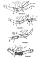
Figure 2 is a perspective view of a first form of the nasal cannula assembly of the present invention. -
Figure 3 is an exploded perspective view of the first form of the nasal cannula assembly ofFigure 2 , showing two parts making up the nasal cannula, a face mount part and gases flow manifold part attached to tubing supplying gases to the patient. -
Figure 4 is a perspective view of a second form of the nasal cannula assembly of the present invention, showing tubing providing gases supply to a gases flow manifold part and face mount part when in connection. -
Figure 5 is a perspective view of the second form of the nasal cannula assembly ofFigure 4 where the gases flow manifold part is disengaged from the face mount part. -
Figure 6 is a perspective view of the second form of the nasal cannula assembly ofFigure 4 where the gases flow manifold part is disengaged from the face mount part, showing the manifold part can be fitted to cither side of the face mount part. -
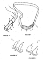
Figure 7 is a back perspective view of the second form of the nasal cannula ofFigure 4 , showing a removable breathable pad on the inner side of the face mount part that abuts the patients face. -
Figure 8 is a perspective view of a third form of the nasal cannula assembly of the present invention, particularly showing a gases flow manifold part that allows for the attachment of removable prongs. -
Figure 9 is a perspective view of the third form of the nasal cannula assembly of the present invention, showing a strap and breathable pad fittable to the manifold part ofFigure 8 . -
Figure 10 is a perspective view of a first form of removable prongs capable of being attached to the manifold part ofFigure 8 . -
Figure 11 is a perspective view of a second form of removable prongs capable of being attached to the manifold part ofFigure 8 . -
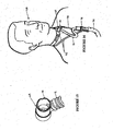
Figure 12 is a perspective view of a patient wearing the nasal cannula assembly ofFigure 4 , showing the use of a neck tie to take some weight of the tubing and a head strap assisting in the maintaining of the assembly to the patient's face. -
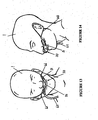
Figure 13 is a front view of a patient wearing a nasal cannula assembly present invention where the assembly is held to the patient's face with the assistance of ear loops. -
Figure 14 is a side view of the patient and nasal cannula assembly ofFigure 13 . -
Figure 15 is a perspective view of a tracheostomy fitting. -
Figure 16 is a front view of a patient with a tracheostomy and fitting attached to a breathing supply where a neck tie or lanyard is used to support the conduit supplying gases to the patient. - Whether used in a hospital environment or in a home environment, the nasal cannula assembly of the present invention will generally have associated three main pieces of apparatus. Firstly an active humidifier that controls the temperature of a heater plate heating a body of water to achieve a desired temperature and humidity of the gases being humidified. Secondly a transport conduit from the humidifier to the patient is also required, which is preferably heated to reduce condensation, or "rain out". Thirdly a nasal cannula designed to fit into the nasal cavity of a patient or user and deliver humidified, pressurized gases.
- Referring to
Figure 1 a humidifying circuit as might be used with the nasal cannula of the present invention is shown. A patient 1 is receiving humidified and pressurised gases through anasal cannula assembly 20 connected to a humidified gases transportation pathway orinspiratory conduit 3 that in turn is connected to a humidifier 8 (including humidification chamber 5) that is supplied with gases from ablower 15 or other appropriate gases supply means. Theinspiratory conduit 3 is connected to the outlet 4 of a humidification chamber 5 which contains a volume of water 6. Humidification chamber 5 is preferably formed from a plastics material and may have a highly heat conductive base (for example an aluminium base) which is in direct contact with a heater plate 7 ofhumidifier 8. Thehumidifier 8 is provided with control means or electronic controller 9 which may comprise a microprocessor based controller executing computer software commands stored in associated memory. Gases flowing through theinspiratory conduit 3 are passed to the patient by way of thenasal cannula 20. - Controller 9 receives input from sources such as user input means or dial 10 through which a user of the device may, for example, set a predetermined required value (preset value) of humidity or temperature of the gases supplied to patient 1. In response to the user set humidity or temperature value input via
dial 10 and other possible inputs such as internal sensors that sense gases flow or temperature, or by parameters calculated in the controller, controller 9 determines when (or to what level) to energise heater plate 7 to heat the water 6 within humidification chamber 5. As the volume of water 6 within humidification chamber 5 is heated, water vapour begins to fill the volume of the chamber above the water's surface and is passed out of the humidification chamber 5 outlet 4 with the flow of gases (for example air) provided from a gases supply means orblower 15 which enters the chamber throughinlet 16. It should be noted that it is possible to obtain the relationship between the humidity of the gases in humidification chamber 5 and the temperature of the heater plate 7. Accordingly, it is possible to utilise the heater plate temperature in an algorithm or a look-up table to determine the humidity of the gases. - The
blower 15 may be provided with a variable speed pump or fan 2 which draws air or other gases through theblower inlet 17. The speed of variable speed pump or fan 2 may be controlled by a further control means or electronic controller 18 (or alternatively the function of thiscontroller 18 could be carried out by the other controller 9) in response to inputs from controller 9 and a user set predetermined required value (preset value) of pressure or fan speed viadial 19. - A heating element 11 may be provided within the conduit or
tubing 3 to help prevent condensation of the humidified gases within the conduit. Such condensation is due to the temperature of the walls of the conduit being close to the ambient temperature, (being the temperature of the surrounding atmosphere) which is usually lower than the temperature of the humidified gases within the conduit. The heater element is effectively replaces the energy lost from the gases through conduction and convection during transit through the conduit. Thus the conduit heater element ensures the gases delivered are at an optimal temperature and humidity. - The nasal cannula assembly of the present invention provides a patient with a patient interface suitable for the delivery of high airflow, high humidity gas flow to the patient's nasal cavity. A particular aspect of the nasal cannula of the present invention is the suitability for long term therapy where the patient, for example, a patient suffering from Chronic Obstructive Pulmonary Disease (COPD), will wear the cannula for several hours per day over weeks, months and in some cases years. Therefore, for patient's to accept use of nasal cannula under these circumstances the cannula need to be unobtrusive, comfortable to wear, noise free, suitable for wearing while sleeping, easy to clean and have prongs that can generate Positive End Expiry Pressure (PEEP). The cannula of the present invention may also be used for other therapies such as for Continuous Positive Airway Pressure (CPAP) therapy and the like.
- A first form of the nasal cannula assembly of the present invention is shown in
Figures 2 and 3 . This nasal cannula assembly, generally indicated as 20, comprises aface mount part 21 including a pair of tubularnasal prongs face mount part 21, and a gases flowmanifold part 24 that is integrally molded with or attached totubing 3, such as that described above. - The
face mount part 21 andprongs manifold part 24 is preferably made from a hard plastics material, although it may be manufactured in other suitable materials. - The
face mount part 21 is preferably integrally molded with theprongs face mount part 21 may be provided with a breathable pad, to be described below. Theouter side 25 of theface mount part 21 has moulded in it an elongatedoval recess 26 and twooval recesses face mount part 21 and each meet the tubular passageway's formed within each of thetubular prongs - The gases flow
manifold part 24 is generally tubular in shape having a substantially circular inlet (not shown) on one side that curves around to an elongatedoval outlet 29. The circular inlet receives the end of the conduit ortubing 3, so that gases are supplied to the gases flowmanifold part 24 and are able to flow through the inlet and out theoutlet 29. Thetubing 3 is preferably permanently fixed to themanifold part 24, but may be releasably attachable. - The
outlet 29, being elongated and oval in shape, fits into theelongated recess 26 in a friction or snap fit engagement with the manifold 21, such that a substantial force is required to remove themanifold part 24 from theelongated recess 26. Further, as theface mount part 21 is flexible and themanifold part 24 made from a harder plastics material it is possible for themanifold part outlet 29 to be easily pushed or forced into theelongated recess 26. When themanifold part 24 is engaged with theface mount part 21 and in use, gases flow from thetubing 3, through the gases flowmanifold part 24 out itsoutlet 29, into each of the oval recesses 27, 28, into each of theprongs - The face mount
part elongate recess 26 andmanifold part outlet 29 are symmetrical in shape and configuration and therefore themanifold part 24 is capable of being switched or flipped such that thetubing 3 extends from either the left or right side of the patient's nares. This means that thenasal cannula assembly 20 and associatedtubing 3 are relatively unobtrusive as thecannula assembly 20 only requires a single horizontal side entry, not two entries as that of the prior art. - The nasal cannula assembly of the present invention is more comfortable to wear as it sits under the septum of the nose and supports the two nasal prongs. As the prongs are made in one moulding of a soft material such as silicone the prongs are easy to insert in the patient's nares and comfortable to the patient.
- For a nasal cannula assembly to be suitable for wearing during sleep each night the cannula must be noise free. Many prior art cannulas are prone to whistling. With a range of airflows generally being between 0 to 40 litres per minute, although airflows of 60 litres per minute are envisaged for the present nasal cannula, and with the air or gases being supplied to a single horizontal entry point it has proved difficult to prevent whistling. For this reason the
face mount part 21 is contoured such that the pressure distribution within theface mount part 21 forces even airflows up each nasal prong. - As the nasal cannula assembly of the present invention is likely to be used while a patient is sleeping, the cannula must be easily tailored for the patients sleeping arrangement. The cannula of the present invention supplies high flow humidified gases to the patient from either the left side or the right side of the cannula thus allowing the minimum length connection circuit to the bedside unit supplying the humidified gas. As the nasal cannula assembly of the present invention allows for the horizontal entry of gases from either side the patient can configure the unit as left or right entry for their particular sleeping arrangement. It is envisaged that the
tubing 3 is approximately two meters in length to allow for added flexibility of the cannula. - Reference is now made to
Figures 4 to 7 that show a second form of the nasal cannula assembly of the present invention. In this form thenasal cannula assembly 30 is of a substantially similar form to the first form described above in relation toFigures 2 and 3 , and has aface mount part 32, a pair ofnasal prongs manifold part 35 andtubing 3. Theface mount part 32 and pair ofnasal prongs - The nasal prongs 33, 34 are tubular in shape and may be consistent in diameter but may be shaped to fit the contours of the human nares.
- A strap or strap attachment means 31 may be integrally formed or attached to the
face mount part 32 in order to enable thenasal cannula assembly 30 to be held in place about a patient's face. - The
face mount part 32 has an opentubular recess 38 extending below thenasal prongs manifold part 35 that is attached to or integrally formed withtubing 3. The tubular passageways within thenasal prongs recess 38. The gases flowmanifold part 35 is blocked at oneend 39 but attached to the tubing at the other end and has anelongate opening 37 that acts as an exit for gases received from thetubing 3. Due to the flexible nature of the material theface mount part 32 is made from, and as the gases flowmanifold part 35 is made from a hard plastics material, the gases flowmanifold part 35 can be pushed through thetubular recess 38 in theface mount part 32 and theelongate opening 37 in the gases flowmanifold part 35 meets with the tubular passageways of theprongs manifold part 35 exit through theopening 37 and into the tubular passageways in theprongs - In order to assist with maintaining the gases flow
manifold part 35 within the opentubular recess 38 themanifold part 35 is provided with an inner recessedportion 60 and contouredlip areas 58, 59. When engaged with theface mount part 32 the tubular body forming therecess 38 sits within the inner recessedportion 60 and the edges of the tubular body abut thelips 58, 59 formed on themanifold part 35. - A breathable pad may be supplied with any of the nasal cannula assemblies described above. In particular, such a
pad 36 is shown inFigure 7 in the second form of the nasal cannula assembly as described above. It must be appreciated that a pad of this type may be provided with any of the other two forms as herein described. - The pad is preferably attached to the inside surface of the
face mount part 32 that connects with the upper lip of the patient wearing the cannula. Thepad 36, which is preferably made from an absorbent cloth, reduces the incidence of heat and moisture on the patient's upper lip, where theface mount part 32 sits against their face. - The
pad 36 is preferably attached to theface mount part 32 by adhesive, for example, the pad could be supplied with a sticky backing that adheres to the face mount part, so that the pad can be easily removed from the face mount part and replaced as necessary. - The pad reduces the effects of heat against the patient's skin and improves hygiene, as any contaminants or cultures that may grow close to the patient's skin, in the warm environment can be removed on removal and replacement of the pad.
- Referring now to
Figures 8 to 11 , a third form of the nasal cannula assembly of the present invention is shown where the nasal cannula assembly comprises three parts. - Firstly, a gases flow
manifold part 40 is shown inFigure 8 which is designed for either left or right hand orientation and provides a symmetrical flow to a pair of nasal cannula assembly prongs 41, 42 (seeFigures 10 or 11 ). - Next, a pair of soft
nasal prongs 41 or 42 are provided that are capable of being attached to the top of the gases flowmanifold part 40 allowing for a large range of different shaped and spaced prongs to be available to the patient. Two such configurations ofprongs 41, 42 are shown inFigures 10 and 11 . The prongs 41 ofFigure 10 are narrow elongatetubular members body 45 that is fittable with the gases flow manifold part 40 (seeFigure 8 ) by appropriate means, for example, friction or snap fit. Theprongs 42 ofFigure 11 are taperedtubular members body 48. Again, thisbody 48 is capable of being fitted (friction, snap or other) to the gases flow manifold part ofFigure 8 . These prongs are preferably made from a soft plastics material such as silicon, although other suitable materials may be used. - With the prongs being removable they are easily cleaned and could also be disinfected for second or subsequent use.
- The third part to the third form of the nasal cannula assembly shown in
Figures 8 to 11 is theface mount part 49 ofFigure 9 . Theface mount part 49 comprises ahead strap 53 attached to a pad 50, that may be a moulded or shaped substantially rigid pad, for example, made from a plastics material such as polypropylene. Thepad 36 may include a breathable cloth pad on its surface that abuts a patient's face, similar to thatpad 36 described in relation toFigure 7 , or the head straps 53 may extend to sit behind the pad. Thehead strap 53 is preferably made from a flexible material, such as neoprene. - The plastic pad 50 is shown in
Figure 9 and has a plurality of apertures 61 formed into to allow for heat and moisture to dissipate from the patient's facial surface. The pad 50 has fastening means 51, 52 for holding the gases flowmanifold part 49 in the correct position on the upper lip of the patient. The fastening means may be clips 51, 52 that are fittable intocomplimentary recesses Figure 8 ), but other appropriate fastening means may be provided with the cannula. An example of other fastening means is a loop that is integrally moulded as part of the prongs which wraps around the face mount part and latches over a protrusion on the manifold part thus encapsulating the face mount part and holding the assembly together stably and securely. Another example of a fastening means is a plastic Velcro™ type attachment where one side would attach to one side of themanifold part 40 and the other side to the plastic pad 50. For the fastening means shown inFigures 8 and 9 at least one recess must be provided on either side of the manifold 40. In the preferred form of the nasal cannula assembly tworecesses other recesses - The attachment between the
face mount part 49 and themanifold part 40 allows for either left or right hand orientation of the manifold part and associated tubing. - It is envisaged the cannula of the present invention will be reusable for several wearings on a single patient and as such the nasal cannula assembly must be hygienic. It is envisaged that all the embodiments of the nasal cannula assembly of the present invention as herein described can be disassembled so that the cannula is easier to clean. The prongs and integrally attached parts are capable of being stored in a sterile solution until reused, much like false teeth are currently stored while not in use.
- With a single flow entry cannula there will be less condensate due to the reduction in surface area for heat loss and thus the cannula of the present invention reduces the effects of condensation building in the tubing and cannula.
- The detachable nasal cannula assembly described in relation to
Figures 8 to 11 allows a patient on long-term therapy to order their particular prong size but maintain a common tubing connection system right to the point of connection into the manifold under the nose. - Often an unheated flexible section of tubing is placed proximal to the patient to reduce torsion or pulling on the patient interface and reduce possible heat problems or over heating close to the patient. In order to reduce condensate forming in the unheated tubing, tubing can be provided that has vapour transmission properties. Referring now to
Figure 12 the nasal cannula of the present invention (in particular, that of the second form described herein) may be provided with a short piece ofbreathable tubing 62 between thenasal cannula 30 andheated tubing 3. Thetubing 62 is preferably made from a material that allows for transmission of water, such as a hydrophilic material, for example SYMPATEX™. - Test results show the performance of a 420mm length of breathable tube, operating with air input at an absolute humidity of 42.2 mg/L, an airflow of 10 litres per minute, in a room with ambient air at 22 degrees C and 50% RH, only lowered the air temperature to 37 and the absolute humidity to 41.15 mg/L at the exit of the dry tube. In comparison a 420mm length of non-breathable but insulated polyethylene tube under exactly the same conditions also output air at 41.15 mg/L. In the breathable tube there was significantly less condensate measured, therefore, some of the humidity that would otherwise be lost as condensate on the wall is being transmitted through the breathable wall.
- The result of providing the short section of
breathable tubing 62 is that a majority of humidity in the gases is transported to the patient, and there is an insignificant and immeasurable loss of humidity through the breathable wall of theshort tube 62, while condensate is reduced. The design of the high airflow high humidity system has been optimized to deliver a breathable gas treatment to patients at temperatures approximating body temperature and fully saturated with water vapour for long treatment periods. The use of an unheated breathable conduit proximal to the patient to provide a connection that is highly flexible and avoids condensation by breathing would be expected to lower the humidity of the gas treatment thereby decreasing the efficacy of the treatment. These results are surprising and are counterintuitive and go some way to explaining why the use of a breathable tube as a short section of tubing before the patient has been overlooked. Thisshort tube 62 is envisaged to be used with any tube delivering heated and humidified gases to a patient. - A neck tie or lanyard may be provided with the nasal cannula assembly of the present invention.
Figure 12 shows such atie 63. Thetie 63 is preferably connected to thetubing 3 or connection 67 between thetubing 3 andbreathable tube 62. Atoggle 64 is preferably provided with theneck tie 63 in order to adjust the neck tie's length. The neck tie has the purpose of taking some of the weight of thetubing 3 and prevents the weight of thetubing 3 pulling on thenasal cannula assembly 30. This helps to prevent the prongs interfering with the very sensitive lining of the nasal passages. The loose fitting neck tie also provides a convenient way of connecting thetubing 3 to the patient outside the blankets. This allows the patient to turn in the bed and avoids thetubing 3 overheating if placed under the blankets. - The tie or lanyard described may be used with any breathing apparatus that supplies gases to a patient; for example it may be used with a nasal or face mask or with a tracheostomy fitting or connector. When the tie or lanyard is used with such apparatus it takes the weight of the conduit(s) or tubing supplying gases to the mask, connector or cannulae and helps reduce the pull on the mask, connector or cannulae.
-
Figures 15 5 and16 show a tracheostomy fitting or connector that may utilise a neck tie or lanyard of the present invention. Thetracheostomy connector 69 attaches to atracheostomy mount 72 that extends into a tracheostomy tube (not shown) through hole in a patient's 68 neck and into their airway passages. Theconnector 69 provides a direct coupling of a tracheostomy tube to the breathing supply of gases received through aconduit 71. Preferably theconduit 71 is constructed in a breathable material, similar to that described above, but may be a heated tube. - The
connector 69 has theconduit 71 attached directly to it and also includes anexpiratory port 70 to allow for expiration of gases. On inspiration no gases flow occurs out theport 70 due to the flow of gases to theconnector 69 being greater than a patient's peak inspiratory flow. Therefore, there is also no or very little entraining of gases from the ambient air. - Excess weight on the tracheostomy tube may cause excess movement of the tube, with the risk of complications such as displacement or recannulation of the tracheostomy, the formation of granulation tissue or more seriously, stomal erosion. To obviate or reduce these problems a tie or
lanyard 73 can be connected to theconduit 71 oradditional connector 74. (that may for example connector theconduit 71 to anadditional conduit 75 that supplies gases). The tie orlanyard 73 transfers the weight of theconduits connector 74 from the tracheostomy tube or mount 72 and distributes it onto the neck of the patient leaving a minimal load directly on the tracheostomy tube ormount 72. Preferably the tie orlanyard 73 is adjustable so that the tie or lanyard length can be altered to suit a patient's requirements. - Orientation of a nasal cannula is an essential requirement to patient comfort. If the nasal cannular is not held firmly in position, it can skew, placing unwanted load on the inside surfaces of the patient's nares. However, to overcome this head gear is often provided with nasal cannula, although, if the head gear is not tight the nasal cannula can still move. This type of tight tension can then compromise patient comfort with pressure on the head and face, while forcing the cannula further up the patient's nose. Ideally nasal cannula should attach to the patient's face in a rigid manner, yet with low loading on the head and face.
- Referring to
Figures 13 and 14 nasal cannula attachment means may be provided to hold thenasal cannula assembly 30 to the patient's face. The attachment means are preferablyear loops straps 31 of theface mount part 32 of thenasal cannula assembly 30. - The
loops face mount part 32 around the patient's ears, and provide rigid anchoring when an inelastic material is used. Theloops loops straps 31, enabling adjustment of length for a comfortable, yet firm fit. - In use, to fit the nasal cannula assembly, a first loop (for example, loop 65) is placed over one car, the nasal cannula assembly positioned on the patient's face and in their nose, then the other ear is passed through the second loop (for example, loop 66), so both loops sit snugly behind the ears. This method of fitting the nasal cannula avoids the initial discomfort of gases being blown into the patient's eyes when the cannula assembly is pulled down the face for fitting with other headgear. Fastening the nasal cannula in this method provides an attachment means that is horizontally secure with minimum tension applied to the ear connection loops. The ear loops have the added advantage for a patient lying on their back that there are no straps behind the back of the head that are moved by head movement on the pillow.
- The features disclosed in the foregoing description, in the claims and/or in the accompanying drawings may, both separately and in any combination thereof, be material for realising the invention in diverse forms thereof.
Claims (16)
- A nasal cannula assembly (20,30) adapted to deliver gases to a patient (1) comprising:a face mount part (21,32), including a pair of tubular nasal prongs (22,23;33, 34) for insertion into the nares of such patient,the disposition of said prongs defining left and right of said nasal cannula assembly,an inspiratory conduit including a gases transport tube (3),a removable gases flow manifold part (24,35) having a single gases entry or inlet which receives one end of said tube (3), the gases flow manifold part being connectable with said face mount part so that in use gases can flow from the tube (3) through the gases manifold part into the face mount part through the nasal prongs and into the patient's nares, characterised in that said gases flow manifold part (24,35) is capable of being fitted with said face mount part (21,32) in two configurations, a first configuration where said tube (3) extends to the left of said nasal cannula assembly (20,30) and a second configuration where said tube (3) extends to the right of said nasal cannula assembly (20,30).
- A nasal cannula assembly (20,30) according to claim 1 wherein said gases flow manifold part (24,35) terminates at an opening (29,37) that in use is aligned with a complementary recess (26,38) in said face mount part (21,32) thereby providing gases flow to said pair of nasal prongs (22,23;33, 34) and said patient's nares.
- A nasal cannula assembly (20,30) according to claim 1 or claim 2 wherein said face mount part (21,32) and said nasal prongs (22,23;33, 34) are integrally moulded from a soft plastics material.
- A nasal cannula assembly (20,30) according to any one of claims 1 to 2 wherein said nasal prongs (22,23;33,34) are detachable from said face mount part (21,32) to allow different sized prongs (22,23;33,34) to be placed on said face mount part (21,32) to suit different sized patients.
- A nasal cannula assembly (20,30) according to any one of claims 1 to 4 wherein said nasal cannula assembly (20,30) includes a breathable pad (36) attached to the inner side of said face mount part (32), such that in use said pad (36) abuts said patient's face in the upper lip region.
- A nasal cannula assembly (20,30) according to claim 5 wherein said pad (36) is removable from said face mount part (21).
- A nasal cannula assembly (20,30) according to any one of claims 1 to 6 wherein said nasal cannula assembly (20,30) also includes loops (65, 66) that extend from said face mount part (32) about said patients' ears in use to attach said nasal cannula assembly (20,30) to said patient (1).
- A nasal cannula assembly (20,30) according to any one of claims 1 to 7 wherein said gases flow manifold part (24,35) is made from a hard plastics material.
- A nasal cannula assembly (20,30) according to any one of claims 1 to 8 wherein the face mount part (21,32) has an open tubular recess (38) extending below the nasal prongs (22,23,33,34) that is capable of receiving the gases flow manifold part (24,35) that is attached to or integrally formed with tubing (3).
- A nasal cannula assembly (20,30) according to claim 9 wherein tubular passageways within the nasal prongs (22,23,33,34) extend through the face mount part (21,32) and into the open tubular recess (38).
- A nasal cannula according to claim 9 or claim 10 wherein the face mount part (21,32) and the nasal prongs (22, 23, 33, 34) are integrally moulded from a soft plastics material, and the gases flow manifold part (35) is made from a hard plastics material, such that in-use the gases flow manifold part (35) can be pushed through an open tubular recess (38) in the face mount part (32) and an elongate opening (37) in the gases flow manifold part (35) meets with tubular passageways of the prongs (33,34), and further in-use, gases flowing through the tubing (3) and into the gases flow manifold part (35), exit through the elongate opening (37) and into the tubular passageways in the prongs (33, 34) then into the patient's nares.
- A nasal cannula assembly (20,30) according to any one of claims 9 to 11 wherein the gases flow manifold part (24,35) is maintained within the open tubular recess (38) by the manifold part (24,35), the manifold part comprising an inner recessed portion (60) and contoured lip areas (58,59), such that, when engaged with the face mount part (32) the tubular body forming the open tubular recess (38) sits within the inner recessed portion (60) and the edges of the tubular body abut the contoured lip areas (58,59) formed on the manifold part (24,35).
- A breathing assistance apparatus comprising:a pressurised source of gases (15),a humidification chamber (5) adapted to, in use, be in fluid communication with said source of gases and adapted to in use humidify said gases,a nasal cannula assembly (20,30) according to any one of claims 1 to 12,said inspiratory conduit being in fluid communication with said humidification chamber (5) for conveying humidified gases from said humidification chamber (5) to said nasal cannula assembly (20,30),heating means (11) disposed within said inspiratory conduit and adapted to heat such gases as they pass through said inspiratory conduit.
- A breathing assistance apparatus according to claim 13 wherein said heating means (11) comprises a heater wire (11) disposed within, throughout or around said inspiratory conduit.
- A breathing assistance apparatus according to claim 13 or claim 14 wherein said breathing assistance apparatus also includes a loose fitting adjustable tie (63) locatable about said patient's neck and adapted to support the weight of said heated inspiratory conduit (3).
- A nasal cannula assembly according to any of claims 1 to 12 wherein said inspiratory conduit (3) includes a short section of tubing (62) constructed of a breathable material, one end of said section of tubing (62) being connected to said gases flow manifold part (24,35).
Priority Applications (4)
| Application Number | Priority Date | Filing Date | Title |
|---|---|---|---|
| EP10182233.6A EP2260895B1 (en) | 2003-05-30 | 2004-05-28 | Breathing assistance apparatus |
| EP21207527.9A EP3970773B1 (en) | 2003-05-30 | 2004-05-28 | Breathing assistance apparatus |
| DK10182233.6T DK2260895T3 (en) | 2003-05-30 | 2004-05-28 | Breathing assistance device. |
| EP17202695.7A EP3338847B1 (en) | 2003-05-30 | 2004-05-28 | Breathing assistance apparatus |
Applications Claiming Priority (2)
| Application Number | Priority Date | Filing Date | Title |
|---|---|---|---|
| NZ52636203 | 2003-05-30 | ||
| NZ52636203 | 2003-05-30 |
Related Child Applications (4)
| Application Number | Title | Priority Date | Filing Date |
|---|---|---|---|
| EP21207527.9A Division EP3970773B1 (en) | 2003-05-30 | 2004-05-28 | Breathing assistance apparatus |
| EP10182233.6A Division-Into EP2260895B1 (en) | 2003-05-30 | 2004-05-28 | Breathing assistance apparatus |
| EP10182233.6A Division EP2260895B1 (en) | 2003-05-30 | 2004-05-28 | Breathing assistance apparatus |
| EP17202695.7A Division EP3338847B1 (en) | 2003-05-30 | 2004-05-28 | Breathing assistance apparatus |
Publications (3)
| Publication Number | Publication Date |
|---|---|
| EP1481702A2 EP1481702A2 (en) | 2004-12-01 |
| EP1481702A3 EP1481702A3 (en) | 2005-06-08 |
| EP1481702B1 true EP1481702B1 (en) | 2012-09-26 |
Family
ID=33129175
Family Applications (4)
| Application Number | Title | Priority Date | Filing Date |
|---|---|---|---|
| EP04012752A Active EP1481702B1 (en) | 2003-05-30 | 2004-05-28 | Breathing assistance apparatus |
| EP10182233.6A Active EP2260895B1 (en) | 2003-05-30 | 2004-05-28 | Breathing assistance apparatus |
| EP17202695.7A Active EP3338847B1 (en) | 2003-05-30 | 2004-05-28 | Breathing assistance apparatus |
| EP21207527.9A Active EP3970773B1 (en) | 2003-05-30 | 2004-05-28 | Breathing assistance apparatus |
Family Applications After (3)
| Application Number | Title | Priority Date | Filing Date |
|---|---|---|---|
| EP10182233.6A Active EP2260895B1 (en) | 2003-05-30 | 2004-05-28 | Breathing assistance apparatus |
| EP17202695.7A Active EP3338847B1 (en) | 2003-05-30 | 2004-05-28 | Breathing assistance apparatus |
| EP21207527.9A Active EP3970773B1 (en) | 2003-05-30 | 2004-05-28 | Breathing assistance apparatus |
Country Status (8)
| Country | Link |
|---|---|
| US (11) | US7493902B2 (en) |
| EP (4) | EP1481702B1 (en) |
| JP (1) | JP4694156B2 (en) |
| AU (1) | AU2004202274B2 (en) |
| CA (7) | CA3017909A1 (en) |
| DK (1) | DK2260895T3 (en) |
| ES (1) | ES2650846T3 (en) |
| HK (1) | HK1257069A1 (en) |
Cited By (22)
| Publication number | Priority date | Publication date | Assignee | Title |
|---|---|---|---|---|
| US8291906B2 (en) | 2008-06-04 | 2012-10-23 | Resmed Limited | Patient interface systems |
| US8297285B2 (en) | 2006-07-28 | 2012-10-30 | Resmed Limited | Delivery of respiratory therapy |
| US8485192B2 (en) | 2005-01-12 | 2013-07-16 | Resmed Limited | Cushion for patient interface |
| US8517023B2 (en) | 2007-01-30 | 2013-08-27 | Resmed Limited | Mask system with interchangeable headgear connectors |
| US8522784B2 (en) | 2008-03-04 | 2013-09-03 | Resmed Limited | Mask system |
| US8733358B2 (en) | 2001-09-07 | 2014-05-27 | Resmed Limited | Cushion for a respiratory mask assembly |
| US8807135B2 (en) | 2004-06-03 | 2014-08-19 | Resmed Limited | Cushion for a patient interface |
| US8869797B2 (en) | 2007-04-19 | 2014-10-28 | Resmed Limited | Cushion and cushion to frame assembly mechanism for patient interface |
| US8869798B2 (en) | 2008-09-12 | 2014-10-28 | Resmed Limited | Foam-based interfacing structure method and apparatus |
| US8905031B2 (en) | 2008-06-04 | 2014-12-09 | Resmed Limited | Patient interface systems |
| US8915251B2 (en) | 2005-06-06 | 2014-12-23 | Resmed Limited | Mask system |
| US8944061B2 (en) | 2005-10-14 | 2015-02-03 | Resmed Limited | Cushion to frame assembly mechanism |
| US9067033B2 (en) | 2003-12-31 | 2015-06-30 | Resmed Limited | Compact oronasal patient interface |
| US9162034B2 (en) | 2006-07-28 | 2015-10-20 | Resmed Limited | Delivery of respiratory therapy |
| US9381316B2 (en) | 2005-10-25 | 2016-07-05 | Resmed Limited | Interchangeable mask assembly |
| US9408988B2 (en) | 2007-10-10 | 2016-08-09 | Parion Sciences, Inc. | Inhaled hypertonic saline delivered by a heated nasal cannula |
| US9480809B2 (en) | 2007-07-30 | 2016-11-01 | Resmed Limited | Patient interface |
| US10252015B2 (en) | 2004-02-23 | 2019-04-09 | Fisher & Paykel Healthcare Limited | Breathing assistance apparatus |
| US10328226B2 (en) | 2008-05-12 | 2019-06-25 | Fisher & Paykel Healthcare Limited | Patient interface and aspects thereof |
| US11324908B2 (en) | 2016-08-11 | 2022-05-10 | Fisher & Paykel Healthcare Limited | Collapsible conduit, patient interface and headgear connector |
| US11554234B2 (en) | 2008-07-18 | 2023-01-17 | Fisher & Paykel Healthcare Limited | Breathing assistance apparatus |
| US11904097B2 (en) | 2015-03-31 | 2024-02-20 | Fisher & Paykel Healthcare Limited | User interface and system for supplying gases to an airway |
Families Citing this family (173)
| Publication number | Priority date | Publication date | Assignee | Title |
|---|---|---|---|---|
| AUPO504597A0 (en) | 1997-02-10 | 1997-03-06 | Resmed Limited | A mask and a vent assembly therefor |
| US6561191B1 (en) | 1997-02-10 | 2003-05-13 | Resmed Limited | Mask and a vent assembly therefor |
| BR0102116B1 (en) | 2000-05-10 | 2010-09-21 | component for a breathing circuit member. | |
| US6581594B1 (en) * | 2000-05-15 | 2003-06-24 | Resmed Limited | Respiratory mask having gas washout vent and gas washout vent for respiratory mask |
| US7559324B2 (en) | 2000-06-21 | 2009-07-14 | Fisher & Paykel Healthcare Limited | Conduit with heated wick |
| AU2003244171B2 (en) | 2002-09-09 | 2007-11-15 | Fisher & Paykel Healthcare Limited | Limb for Breathing Circuit |
| NZ553302A (en) | 2002-11-06 | 2008-10-31 | Resmed Ltd | Mask assembly with frame that can be flexed about longitudinal axis |
| AU2004202274B2 (en) | 2003-05-30 | 2006-10-26 | Fisher & Paykel Healthcare Limited | Breathing Assistance Apparatus |
| US7588033B2 (en) | 2003-06-18 | 2009-09-15 | Breathe Technologies, Inc. | Methods, systems and devices for improving ventilation in a lung area |
| US8225796B2 (en) * | 2003-07-28 | 2012-07-24 | Salter Labs | Respiratory therapy system including a nasal cannula assembly |
| AU2004266693B2 (en) | 2003-08-18 | 2011-03-10 | Breathe Technologies, Inc | Method and device for non-invasive ventilation with nasal interface |
| AU2004203870B2 (en) | 2003-09-17 | 2011-03-03 | Fisher & Paykel Healthcare Limited | Breathable Respiratory Mask |
| US7856982B2 (en) * | 2004-03-11 | 2010-12-28 | Ric Investments, Llc | Patient interface device |
| EP3763411A1 (en) | 2004-03-31 | 2021-01-13 | Fisher & Paykel Healthcare Limited | Catheter mount for a patient ventilating and aspirating system |
| EP1737524B1 (en) | 2004-04-02 | 2018-10-10 | Fisher & Paykel Healthcare Limited | Breathing assistance apparatus |
| NZ586208A (en) | 2004-04-09 | 2012-01-12 | Resmed Ltd | A nasal assembly with a vent where at least one end of the vent has a moulding seam positioned out of the main air stream of the vent |
| US8061357B2 (en) | 2004-12-08 | 2011-11-22 | Ventus Medical, Inc. | Adhesive nasal respiratory devices |
| US9833354B2 (en) | 2004-12-08 | 2017-12-05 | Theravent, Inc. | Nasal respiratory devices |
| MX338506B (en) | 2004-12-08 | 2016-04-20 | Ventus Medical Inc | Respiratory devices and methods of use. |
| US10610228B2 (en) | 2004-12-08 | 2020-04-07 | Theravent, Inc. | Passive nasal peep devices |
| DE102005000922A1 (en) * | 2005-01-07 | 2006-07-20 | Seleon Gmbh | Aerial goggles, nosepiece, Y-piece and procedures |
| US20060266359A1 (en) * | 2005-02-28 | 2006-11-30 | Van Beurden Jason P | Pressure relief valve |
| JP4741884B2 (en) * | 2005-06-09 | 2011-08-10 | 帝人ファーマ株式会社 | Breathing gas supply cannula |
| CN101454041B (en) | 2005-09-20 | 2012-12-12 | 呼吸科技公司 | Systems, methods and apparatus for respiratory support of a patient |
| US7640934B2 (en) * | 2005-12-02 | 2010-01-05 | Carefusion 2200, Inc. | Infant nasal interface prong device |
| CN103463722B (en) * | 2005-12-15 | 2015-12-09 | 菲舍尔和佩克尔保健有限公司 | Respiratory assistance apparatus |
| US20100059053A1 (en) * | 2006-03-23 | 2010-03-11 | Vapotherm Inc. | Apparatus configured to reduce microbial infection and method of making the same |
| USD623288S1 (en) | 2006-04-28 | 2010-09-07 | Resmed Limited | Patient interface |
| CN101541365A (en) | 2006-05-18 | 2009-09-23 | 呼吸科技公司 | Tracheostoma tracheotomy method and device |
| GB0610171D0 (en) | 2006-05-23 | 2006-06-28 | Robitaille Jean Pierre | Valved nasal canula |
| CN101489630B (en) | 2006-06-07 | 2013-10-23 | 温吐斯医学公司 | Layered nasal devices |
| AU2007258524B2 (en) | 2006-06-07 | 2012-05-03 | Ventus Medical, Inc. | Layered nasal devices |
| CN102631741B (en) | 2006-07-14 | 2015-11-04 | 菲舍尔和佩克尔保健有限公司 | Respiratory assist system |
| NZ776317A (en) * | 2006-07-28 | 2023-01-27 | ResMed Pty Ltd | Delivery of respiratory therapy |
| JP2009545384A (en) | 2006-08-03 | 2009-12-24 | ブリーズ テクノロジーズ, インコーポレイテッド | Method and apparatus for minimally invasive respiratory assistance |
| US8161971B2 (en) | 2006-08-04 | 2012-04-24 | Ric Investments, Llc | Nasal and oral patient interface |
| EP2051761B1 (en) | 2006-08-04 | 2019-08-21 | ResMed Pty Ltd | Nasal prongs for mask system |
| US8240309B2 (en) | 2006-11-16 | 2012-08-14 | Ventus Medical, Inc. | Adjustable nasal devices |
| JP5911189B2 (en) | 2006-12-15 | 2016-04-27 | レスメド・リミテッドResMed Limited | Respiratory therapy |
| WO2008144589A1 (en) | 2007-05-18 | 2008-11-27 | Breathe Technologies, Inc. | Methods and devices for sensing respiration and providing ventilation therapy |
| US8677993B2 (en) | 2007-07-18 | 2014-03-25 | Vapotherm, Inc. | Humidifier for breathing gas heating and humidification system |
| US8215301B2 (en) | 2007-08-29 | 2012-07-10 | Smiths Medical Asd, Inc. | Nose cannula heated/humidified gas delivery system |
| US8196579B2 (en) | 2007-08-29 | 2012-06-12 | Smiths Medical Asd, Inc. | Nose cannula heated/humidified gas delivery system |
| CN101873875B (en) | 2007-09-26 | 2014-11-12 | 呼吸科技公司 | Methods and devices for providing inspiratory and expiratory flow relief during ventilation therapy |
| CN101888868B (en) | 2007-09-26 | 2014-01-22 | 呼吸科技公司 | Methods and devices for treating sleep apnea |
| US8905023B2 (en) | 2007-10-05 | 2014-12-09 | Vapotherm, Inc. | Hyperthermic humidification system |
| AU2014221224B2 (en) * | 2007-10-10 | 2017-06-08 | Parion Sciences, Inc. | Delivering osmolytes by nasal cannula |
| US8772681B2 (en) * | 2007-11-15 | 2014-07-08 | Electronic Instrumentation And Technology, Inc. | Method and apparatus for forced air heater measurement and control |
| JP5462798B2 (en) * | 2007-11-19 | 2014-04-02 | コーニンクレッカ フィリップス エヌ ヴェ | Patient interface device including a coating adhesive layer |
| US8020700B2 (en) | 2007-12-05 | 2011-09-20 | Ventus Medical, Inc. | Packaging and dispensing nasal devices |
| CN101977648A (en) * | 2008-01-25 | 2011-02-16 | 索尔特实验室 | Respiratory therapy system including a nasal cannula assembly |
| AU2009212689A1 (en) * | 2008-02-01 | 2009-08-13 | Ventus Medical, Inc. | CPAP interface and backup devices |
| US11331447B2 (en) | 2008-03-04 | 2022-05-17 | ResMed Pty Ltd | Mask system with snap-fit shroud |
| WO2009108994A1 (en) | 2008-03-04 | 2009-09-11 | Resmed Ltd | A foam respiratory mask |
| NZ608162A (en) | 2008-03-04 | 2014-11-28 | Resmed Ltd | An interface including a foam cushioning element |
| NZ747465A (en) | 2008-03-04 | 2020-05-29 | ResMed Pty Ltd | Unobtrusive interface systems |
| US8776793B2 (en) | 2008-04-18 | 2014-07-15 | Breathe Technologies, Inc. | Methods and devices for sensing respiration and controlling ventilator functions |
| US8770193B2 (en) | 2008-04-18 | 2014-07-08 | Breathe Technologies, Inc. | Methods and devices for sensing respiration and controlling ventilator functions |
| EP2113274B1 (en) | 2008-04-30 | 2016-04-27 | ResMed R&D Germany GmbH | Apparatus for controlled delivery of a breathing gas to the respiratory tracts of a user |
| US10258757B2 (en) | 2008-05-12 | 2019-04-16 | Fisher & Paykel Healthcare Limited | Patient interface and aspects thereof |
| AU2009251939B2 (en) * | 2008-05-27 | 2015-08-06 | Fisher & Paykel Healthcare Limited | Control of humidifier chamber temperature for accurate humidity control |
| US10071216B2 (en) | 2008-05-29 | 2018-09-11 | Naturs Design, Inc. | Liner for use with respiratory mask |
| US11305082B2 (en) | 2008-05-29 | 2022-04-19 | Naturs Design, Inc. | Liner for use with respiratory mask |
| NZ742900A (en) | 2008-06-05 | 2020-02-28 | ResMed Pty Ltd | Treatment of respiratory conditions by automatic control of flow and/or temperature and/or humidity independently to nares via separate flow paths |
| CA2734296C (en) | 2008-08-22 | 2018-12-18 | Breathe Technologies, Inc. | Methods and devices for providing mechanical ventilation with an open airway interface |
| JP5711661B2 (en) | 2008-10-01 | 2015-05-07 | ブリーズ・テクノロジーズ・インコーポレーテッド | Ventilator with biofeedback monitoring and controls to improve patient activity and health |
| EP2349428B1 (en) * | 2008-10-10 | 2017-09-20 | Fisher & Paykel Healthcare Limited | Nasal pillows for a patient interface |
| DE102009047246A1 (en) * | 2008-12-01 | 2010-06-10 | Fisher & Paykel Healthcare Ltd., East Tamaki | nasal cannula |
| WO2010115166A1 (en) | 2009-04-02 | 2010-10-07 | Breathe Technologies, Inc. | Methods, systems and devices for non-invasive open ventilation with gas delivery nozzles in free space |
| US9132250B2 (en) | 2009-09-03 | 2015-09-15 | Breathe Technologies, Inc. | Methods, systems and devices for non-invasive ventilation including a non-sealing ventilation interface with an entrainment port and/or pressure feature |
| EP2213324B1 (en) | 2009-01-30 | 2016-07-27 | ResMed R&D Germany GmbH | Patient interface structure and method/tool for manufacturing same |
| US9962512B2 (en) | 2009-04-02 | 2018-05-08 | Breathe Technologies, Inc. | Methods, systems and devices for non-invasive ventilation including a non-sealing ventilation interface with a free space nozzle feature |
| WO2011029074A1 (en) | 2009-09-03 | 2011-03-10 | Breathe Technologies, Inc. | Methods, systems and devices for non-invasive ventilation including a non-sealing ventilation interface with an entrainment port and/or pressure feature |
| CN102039012A (en) * | 2009-10-26 | 2011-05-04 | 吴福吉 | Portable air purifier |
| US8042547B2 (en) * | 2009-11-16 | 2011-10-25 | Joseph Goldstein | Respiratory shield |
| EP2501423A4 (en) | 2009-11-18 | 2014-10-29 | Fisher & Paykel Healthcare Ltd | Nasal interface |
| CA3177059A1 (en) | 2009-12-22 | 2011-06-30 | Fisher & Paykel Healthcare Limited | Components for medical circuits |
| CA2785454C (en) | 2009-12-23 | 2020-05-19 | Fisher & Paykel Healthcare Limited | An interface |
| SE534855C2 (en) * | 2010-03-16 | 2012-01-24 | Heinberger Handelsbolag | Device for sleep apnea |
| US8875711B2 (en) | 2010-05-27 | 2014-11-04 | Theravent, Inc. | Layered nasal respiratory devices |
| US20110303224A1 (en) * | 2010-06-12 | 2011-12-15 | Widgerow Alan D | Skin adherent medical devices |
| CN103096981B (en) | 2010-08-16 | 2015-07-22 | 呼吸科技公司 | Methods, systems and devices using lox to provide ventilatory support |
| US8939152B2 (en) * | 2010-09-30 | 2015-01-27 | Breathe Technologies, Inc. | Methods, systems and devices for humidifying a respiratory tract |
| WO2012047121A1 (en) | 2010-10-08 | 2012-04-12 | Fisher & Paykel Healthcare Limited | Breathing assistance apparatus |
| EP3556416B1 (en) * | 2010-10-18 | 2023-11-29 | Fisher & Paykel Healthcare Limited | A nasal cannula, conduit and securement system |
| US9199053B1 (en) * | 2011-01-31 | 2015-12-01 | Breathe Technologies, Inc. | Methods, systems and devices for ventilation using a nasal ventilation mask with a manifold and internal compliant tube and nasal sealing cushion assembly |
| CN103732213A (en) | 2011-06-07 | 2014-04-16 | 帕里昂科学公司 | Methods of treatment |
| US8839791B2 (en) | 2011-06-22 | 2014-09-23 | Breathe Technologies, Inc. | Ventilation mask with integrated piloted exhalation valve |
| US9486602B2 (en) | 2011-06-22 | 2016-11-08 | Breathe Technologies, Inc. | Ventilation mask with integrated piloted exhalation valve and method of ventilating a patient using the same |
| US9038634B2 (en) | 2011-06-22 | 2015-05-26 | Breathe Technologies, Inc. | Ventilation mask with integrated piloted exhalation valve |
| EP3718586B1 (en) | 2011-07-12 | 2023-11-29 | ResMed Pty Ltd | Textile mask systems |
| JP6346089B2 (en) | 2011-08-10 | 2018-06-20 | フィッシャー アンド ペイケル ヘルスケア リミテッド | Conduit connector for patient breathing device |
| WO2013046013A1 (en) | 2011-09-29 | 2013-04-04 | Trudell Medical International | Nasal insert and cannula and methods for the use thereof |
| AU2013212314B2 (en) | 2012-01-24 | 2017-08-17 | Vapotherm, Inc | Systems and methods for providing respiratory therapy |
| CA3207604A1 (en) | 2012-04-05 | 2013-10-10 | Fisher & Paykel Healthcare Limited | Breathing assistance apparatus with serviceability features |
| CN104411355B (en) | 2012-05-02 | 2017-11-03 | 费雪派克医疗保健有限公司 | Respiratory humidification device communication system and method |
| CN107626023B (en) | 2012-08-08 | 2021-03-02 | 费雪派克医疗保健有限公司 | Interface assembly for use in providing respiratory therapy |
| CA3130843A1 (en) | 2012-08-08 | 2014-02-13 | Fisher & Paykel Healthcare Limited | Breathing tube assemblies with adjustable elbow |
| US10300236B2 (en) * | 2012-10-31 | 2019-05-28 | Vapotherm, Inc. | Quiet nasal cannula |
| DE112013005483T5 (en) | 2012-11-16 | 2015-08-13 | Fisher & Paykel Healthcare Limited | Nose gasket and ventilation interface |
| ES2773718T3 (en) | 2012-12-04 | 2020-07-14 | Mallinckrodt Hospital Products Ip Ltd | Cannula to minimize dissolution of the dosage during administration of nitric oxide |
| US9795756B2 (en) | 2012-12-04 | 2017-10-24 | Mallinckrodt Hospital Products IP Limited | Cannula for minimizing dilution of dosing during nitric oxide delivery |
| US9878121B2 (en) | 2013-03-13 | 2018-01-30 | Breathe Technologies, Inc. | Ventilation mask with heat and moisture exchange device |
| EP3827863B1 (en) | 2013-03-14 | 2023-06-07 | Fisher & Paykel Healthcare Limited | Catheter mount with suction port |
| CA2903966C (en) * | 2013-03-15 | 2023-04-25 | Fisher & Paykel Healthcare Limited | Nasal cannula assemblies and related parts |
| CA2911413A1 (en) * | 2013-05-07 | 2014-11-13 | Fisher & Paykel Healthcare Limited | Patient interface and headgear for a respiratory apparatus |
| US10357626B1 (en) | 2013-07-23 | 2019-07-23 | Bruce O. Baker | Liner for a respirator mask |
| US10569043B2 (en) | 2013-08-09 | 2020-02-25 | Fisher & Paykel Healthcare Limited | Asymmetrical nasal delivery elements and fittings for nasal interfaces |
| US10709861B2 (en) * | 2013-09-20 | 2020-07-14 | Fisher & Paykel Healthcare Limited | Nasal cannula with flow restrictor |
| WO2015041547A1 (en) * | 2013-09-23 | 2015-03-26 | Fisher & Paykel Healthcare Limited | Nasal cannula with turbulation elements |
| US11110242B2 (en) * | 2013-10-16 | 2021-09-07 | Fisher & Paykel Healthcare Limited | Patient interface |
| USD747792S1 (en) * | 2013-10-25 | 2016-01-19 | Fisher & Paykel Health Care Limited | Nasal cannula body |
| PL3939645T3 (en) * | 2014-03-27 | 2024-03-18 | Fisher & Paykel Healthcare Limited | Pressurizing mask |
| USD766711S1 (en) | 2014-04-17 | 2016-09-20 | Fisher & Paykel Healthcare Limited | Clip |
| SG10201811322SA (en) * | 2014-06-18 | 2019-01-30 | Fisher & Paykel Healthcare Ltd | Patient interface and component parts |
| USD810926S1 (en) | 2014-06-27 | 2018-02-20 | Bruce O. Baker | Liner for respirator mask |
| JP6903573B2 (en) * | 2014-09-19 | 2021-07-14 | フィッシャー アンド ペイケル ヘルスケア リミテッド | Patient interface |
| US10596345B2 (en) | 2014-12-31 | 2020-03-24 | Vapotherm, Inc. | Systems and methods for humidity control |
| US10398871B2 (en) | 2015-03-31 | 2019-09-03 | Vapotherm, Inc. | Systems and methods for patient-proximate vapor transfer for respiratory therapy |
| CN112891694A (en) * | 2015-03-31 | 2021-06-04 | 费雪派克医疗保健有限公司 | Apparatus for use in a respiratory support system |
| CA2980520A1 (en) | 2015-03-31 | 2016-10-06 | Fisher & Paykel Healthcare Limited | Methods and apparatus for high gas flow |
| US10441736B2 (en) | 2015-04-24 | 2019-10-15 | Fisher & Paykel Healthcare Limited | Respiratory mask with cheek supports |
| US11376389B2 (en) | 2015-05-04 | 2022-07-05 | Smart Bridge Medical, Inc. | Tracheal tube apparatus and methods |
| US9833588B2 (en) * | 2015-05-04 | 2017-12-05 | Smart Bridge Medical, Inc. | Tracheal tube apparatus and methods |
| EP3906958B1 (en) * | 2016-03-02 | 2023-02-15 | Fisher & Paykel Healthcare Limited | Nasal respiratory interface and adjustable headgear |
| CN106390260A (en) * | 2016-09-08 | 2017-02-15 | 深圳永胜宏基医疗器械有限公司 | Breathing nasal plug with sealant positions |
| USD870269S1 (en) | 2016-09-14 | 2019-12-17 | Fisher & Paykel Healthcare Limited | Nasal cannula assembly |
| CN213642639U (en) | 2016-10-14 | 2021-07-09 | 蒸汽热能公司 | System for fluid circulation in a respiratory therapy unit and vapor transfer system |
| DE102017003534B4 (en) | 2016-11-04 | 2021-06-24 | Tni Medical Ag | Tracheal Applicator and Associated Use |
| DE102016014752B4 (en) | 2016-12-13 | 2024-02-29 | Drägerwerk AG & Co. KGaA | Reversible nasal cannula for high-flow ventilation |
| USD849236S1 (en) | 2016-12-19 | 2019-05-21 | Bruce O. Baker | Liner for respirator mask |
| USD874646S1 (en) | 2017-03-09 | 2020-02-04 | Fisher & Paykel Healthcare Limited | Headgear component for a nasal mask assembly |
| USD901673S1 (en) | 2017-03-09 | 2020-11-10 | Fisher & Paykel Healthcare Limited | Frame and breathing tube assembly for a nasal mask |
| TWI622412B (en) * | 2017-04-20 | 2018-05-01 | Hsiner Co Ltd | Breathing mask |
| CN110944704B (en) | 2017-05-22 | 2022-12-23 | 菲舍尔和佩克尔保健有限公司 | Respiratory user interface |
| USD875242S1 (en) | 2017-09-20 | 2020-02-11 | Fisher & Paykel Healthcare Limited | Nasal mask and breathing tube set |
| USD855793S1 (en) | 2017-09-20 | 2019-08-06 | Fisher & Paykel Healthcare Limited | Frame for a nasal mask |
| US10792449B2 (en) | 2017-10-03 | 2020-10-06 | Breathe Technologies, Inc. | Patient interface with integrated jet pump |
| CN107715339B (en) * | 2017-11-03 | 2022-09-13 | 温州市中心医院 | Infectious department purifies formula and breathes nursing device |
| USD849242S1 (en) | 2017-11-21 | 2019-05-21 | Fisher & Paykel Healthcare Limited | Nasal cannula assembly |
| USD878549S1 (en) | 2017-11-21 | 2020-03-17 | Fisher & Paykel Healthcare Limited | Connector for nasal cannula assembly |
| USD849243S1 (en) | 2017-11-21 | 2019-05-21 | Fisher & Paykel Healthcare Limited | Nasal cannula |
| USD848614S1 (en) | 2017-11-21 | 2019-05-14 | Fisher & Paykel Healthcare Limited | Pad for nasal cannula assembly |
| CN111770740A (en) | 2018-01-08 | 2020-10-13 | 维沃尼克斯股份有限公司 | System and method for cooling the brain of a human body |
| CN108386945A (en) * | 2018-01-19 | 2018-08-10 | 昆山苏熙莱卡电子科技有限公司 | A kind of novel air humidifier |
| CA3094530A1 (en) | 2018-03-27 | 2019-10-03 | Naturs Design, Inc. | Liner and retaining member for use with respiratory mask |
| CN110152141A (en) * | 2018-04-03 | 2019-08-23 | 刘桂英 | A kind of portable oxygen supply device of emergency care |
| TWI657838B (en) * | 2018-04-03 | 2019-05-01 | 貝斯美德股份有限公司 | Nasal cannula having sliding track mechanism |
| CN112135653A (en) | 2018-05-14 | 2020-12-25 | 柯惠有限合伙公司 | System and method for ventilation humidification |
| KR20210031424A (en) | 2018-05-31 | 2021-03-19 | 베이포썸, 인코포레이티드 | Machine adjacent sprayer |
| GB2575051B (en) * | 2018-06-26 | 2022-08-24 | Draeger Safety Uk Ltd | Connection apparatus for breathing apparatus |
| US11071842B2 (en) * | 2018-07-09 | 2021-07-27 | Perma Pure Llc | Low-flow oxygen therapy humidifier and method |
| US20200016360A1 (en) * | 2018-07-11 | 2020-01-16 | Martin Allan Morris | Low flow adaptor to deliver aerosols via nasal cannula without crashout |
| US10314999B1 (en) * | 2018-08-23 | 2019-06-11 | Baiping Lei | Nasal breathing apparatus and method for high-flow therapy and non-invasive ventilation |
| DE102018122516A1 (en) | 2018-09-14 | 2020-03-19 | Hamilton Medical Ag | Nasal cannula with improved, also asymmetrical flow guidance |
| US11771861B2 (en) * | 2018-10-16 | 2023-10-03 | Branden Boye | CPAP tether |
| CA3122724A1 (en) | 2018-12-10 | 2020-06-18 | Fisher & Paykel Healthcare Limited | Respiratory interface |
| USD1006981S1 (en) | 2019-09-06 | 2023-12-05 | Fisher & Paykel Healthcare Limited | Breathing conduit |
| USD948027S1 (en) | 2019-09-10 | 2022-04-05 | Fisher & Paykel Healthcare Limited | Connector for a breathing conduit |
| EP4353288A2 (en) | 2019-09-26 | 2024-04-17 | Vapotherm, Inc. | Internal cannula mounted nebulizer |
| USD957622S1 (en) * | 2019-10-16 | 2022-07-12 | Aires Medical LLC | Nasal cannula |
| WO2021080551A1 (en) * | 2019-10-21 | 2021-04-29 | Devarasetty Pratyush Pavan | Systems, devices, and methods for detecting physical distress in infant tracheostomy patients |
| CN110833647A (en) * | 2019-11-27 | 2020-02-25 | 天津怡和嘉业医疗科技有限公司 | Patient interface device and ventilation therapy apparatus |
| US11219255B2 (en) * | 2020-04-08 | 2022-01-11 | Terry Earl Brady | Self-contained, mobile breathing apparatus or appliance that supplies pathogen and endotoxin free, rhythmically breathable air to the wearer or treated space through active, continuous bio-deactivation and destruction of bacteria, fungi, viral and allergenic/antigenic matter safely when using benign, household, rechargeable filtration media |
| GB2594936A (en) | 2020-05-06 | 2021-11-17 | Intersurgical Ag | Nasal interface |
| US20200376305A1 (en) | 2020-06-10 | 2020-12-03 | Noah Lang | Personal protective equipment system for safe air, train or bus travel protecting against infectious agents including novel coronavirus - covid-19 |
| CN112189919A (en) * | 2020-10-14 | 2021-01-08 | 湖南小红服装有限公司 | Medical protective clothing convenient to use |
| USD974551S1 (en) | 2020-12-09 | 2023-01-03 | Fisher & Paykel Healthcare Limited | Connector assembly and connector |
| USD1019935S1 (en) | 2021-05-26 | 2024-03-26 | Athfar 828, Inc. | Liner for respirator mask |
| USD995758S1 (en) | 2021-06-11 | 2023-08-15 | Fisher & Paykel Healthcare Limited | Tube assembly and connector |
| WO2023075610A1 (en) * | 2021-10-26 | 2023-05-04 | Fisher & Paykel Healthcare Limited | A patient interface system |
| USD1012277S1 (en) | 2021-11-02 | 2024-01-23 | American Pillar, Inc. | Liner for respirator mask |
| CN113769224B (en) * | 2021-11-12 | 2022-11-29 | 广东九科医疗设备有限公司 | Nasal obstruction type breathing and ventilating instrument |
Family Cites Families (266)
| Publication number | Priority date | Publication date | Assignee | Title |
|---|---|---|---|---|
| DE28036C (en) * | 1884-02-12 | 1884-07-23 | J. WOLFF in Grofs-Gerau, Gr. Hessen | Outdoor breathers |
| US928237A (en) | 1908-12-16 | 1909-07-20 | John P Baird | Hose-coupling. |
| GB191509683A (en) | 1915-12-22 | 1916-09-21 | Edgar George Payne | Improvements in, or connected with, Ambulances, Stretchers, Litters, and the like. |
| GB587163A (en) | 1944-02-04 | 1947-04-16 | Wingfoot Corp | Improvements relating to tubes or packages and methods of making the same |
| US2868199A (en) * | 1955-05-20 | 1959-01-13 | Charles H Hudson | Cannula |
| GB975819A (en) | 1960-04-01 | |||
| BE608328A (en) | 1960-09-19 | |||
| US3303105A (en) | 1963-03-25 | 1967-02-07 | Gen Electric | Diffusion of water vapor through slicone rubber |
| US3376181A (en) | 1963-07-31 | 1968-04-02 | Continental Can Co | Method and apparatus for blowing plastic liner in continuously formed tubes having longitudinal seam |
| US3245206A (en) | 1963-08-02 | 1966-04-12 | Engelhard Ind Inc | Diffusion purification apparatus |
| US3292346A (en) | 1964-03-06 | 1966-12-20 | Renard P Adams | Gas drying apparatus |
| US3367850A (en) | 1964-12-07 | 1968-02-06 | Exxon Research Engineering Co | Method and apparatus for determining moisture content of hydrocarbon fluids |
| US3307330A (en) | 1965-04-30 | 1967-03-07 | Du Pont | Diffusion process and apparatus |
| US3434471A (en) | 1966-04-06 | 1969-03-25 | Smithkline Corp | Therapeutic intermittent positive pressure respirator |
| US3394954A (en) | 1966-05-06 | 1968-07-30 | Sarns Inc | Tube coupling for medical appliances |
| US3513844A (en) * | 1968-04-30 | 1970-05-26 | Metro Hospital Supply Co Inc | Adjustable nonrestrictive nasal cannula |
| US3578777A (en) | 1969-06-11 | 1971-05-18 | Koppy Tool Corp | Corrugated tubing |
| US3616796A (en) | 1969-06-30 | 1971-11-02 | Richard Robert Jackson | Humidified respiratory tube and method |
| US3700513A (en) | 1969-09-18 | 1972-10-24 | Spiess C F & Sohn | Method of making tube |
| US3639970A (en) | 1969-10-02 | 1972-02-08 | Phillips Petroleum Co | Method and apparatus for forming plastic-lined metal conduit |
| US3829340A (en) | 1971-03-17 | 1974-08-13 | Western Electric Co | Methods of making a tubular member having a sealed longitudinal seam |
| US3682171A (en) * | 1971-03-31 | 1972-08-08 | Baxter Laboratories Inc | Nasal cannula |
| US3754552A (en) * | 1971-06-08 | 1973-08-28 | Sandoz Ag | Flexible nasal cannula |
| US3735558A (en) | 1971-06-29 | 1973-05-29 | Perma Pure Process Inc | Process for separating fluids and apparatus |
| US3891556A (en) | 1971-11-15 | 1975-06-24 | Oxy Metal Ind Intra Inc | Multi-layer braided tubular membrane reinforcement |
| US3735559A (en) | 1972-02-02 | 1973-05-29 | Gen Electric | Sulfonated polyxylylene oxide as a permselective membrane for water vapor transport |
| US3856051A (en) | 1972-02-28 | 1974-12-24 | J Bain | Flexible tube device |
| US3803810A (en) | 1972-05-01 | 1974-04-16 | Pall Corp | Liquid-gas separator and filter |
| US3910808A (en) | 1972-08-30 | 1975-10-07 | Steward Plastics | Apparatus for making helically wound plastic tubing |
| DE2321553C2 (en) | 1972-08-30 | 1983-10-20 | Steward Plastics, Inc., Santa Ana, Calif. | Device for producing a helically wound flexible pipe |
| US3871373A (en) | 1972-10-30 | 1975-03-18 | Richard R Jackson | Humidifying gas |
| US3912795A (en) | 1972-10-30 | 1975-10-14 | Richard R Jackson | Humidifying gas |
| US3895630A (en) | 1973-06-04 | 1975-07-22 | Del Mar Eng Lab | Respiratory gas analyzer including a carbon dioxide and respiratory quotient computer |
| US3889717A (en) | 1973-12-14 | 1975-06-17 | Deere & Co | Reinforced flexible tube |
| US4007737A (en) | 1974-01-28 | 1977-02-15 | Paluch Bernard R | Anesthesia breathing system |
| CH581474A5 (en) | 1974-06-27 | 1976-11-15 | Draegerwerk Ag | |
| US4035211A (en) | 1974-07-02 | 1977-07-12 | Western Electric Company, Inc. | Forming sealed seams in moisture barriers for cable |
| US3963856A (en) | 1974-11-25 | 1976-06-15 | Steward Plastics, Inc. | Flexible, corrugated, plastic tubing having conductive helical bead |
| DE2529050C2 (en) | 1975-06-30 | 1983-01-05 | Drägerwerk AG, 2400 Lübeck | Moisture exchanger in devices for breathing and anesthesia |
| DE2711236C2 (en) | 1976-05-14 | 1982-09-23 | Shiro Osaka Ibaragi Kanao | Method and device for the continuous production of a pipe |
| US4083245A (en) | 1977-03-21 | 1978-04-11 | Research Development Corporation | Variable orifice gas flow sensing head |
| US4086035A (en) | 1977-03-18 | 1978-04-25 | Klaeger Jr Joseph Hart | Bailer pumps for oil wells |
| US4327775A (en) | 1977-05-09 | 1982-05-04 | The Gates Rubber Company | Formable hose with a reformable insert |
| US4130617A (en) | 1977-12-30 | 1978-12-19 | Airco, Inc. | Method of making endotracheal tube cuffs |
| US4204562A (en) | 1978-04-27 | 1980-05-27 | Kelly Walter F | Two-ply duct core |
| US4207457A (en) | 1978-06-29 | 1980-06-10 | The Kanthal Corporation | Porcupine wire coil electric resistance fluid heater |
| US4194041A (en) | 1978-06-29 | 1980-03-18 | W. L. Gore & Associates, Inc. | Waterproof laminate |
| US4262704A (en) | 1978-08-30 | 1981-04-21 | Caterpillar Tractor Co. | High pressure reinforced hydraulic hose |
| US4248218A (en) | 1978-09-22 | 1981-02-03 | Fischer Charles M | Gas administration scavenging mask |
| US4216769A (en) * | 1978-09-29 | 1980-08-12 | Grimes Jerry L | Bi-flow nasal cup |
| US4265239A (en) | 1978-11-27 | 1981-05-05 | Fischer Jr Charles M | Gas scavenging exhaust system |
| US4265235A (en) | 1979-05-11 | 1981-05-05 | Fukunaga Atsuo F | Anesthetic system |
| DE2929584A1 (en) | 1979-07-21 | 1981-02-05 | Draegerwerk Ag | MOISTURE EXCHANGER IN BREATHING DEVICES |
| JPS5689531A (en) | 1979-12-20 | 1981-07-20 | Toyo Chem Co Ltd | Corrugated pipe |
| US4367735A (en) | 1979-12-31 | 1983-01-11 | Novametrix Medical Systems, Inc. | Nasal cannula |
| US4456034A (en) | 1980-02-19 | 1984-06-26 | Bixby Guy T | Formable hose |
| US4406514A (en) | 1980-03-26 | 1983-09-27 | Harris Corporation | Single fiber connector for pluggable card or module optical interconnections |
| US4403514A (en) | 1980-05-20 | 1983-09-13 | Critikon, Inc. | Pneumotachograph with pitot-like tubes |
| US4337800A (en) | 1980-07-07 | 1982-07-06 | Steward Plastics, Inc. | Two piece extruded hose |
| US4327718A (en) | 1980-09-18 | 1982-05-04 | Becton, Dickinson And Company | Continuously draining trap for removal of condensate from a patient breathing circuit |
| US4653542A (en) | 1980-10-02 | 1987-03-31 | The Kendall Company | Medical tubing and connector |
| US4336798A (en) | 1980-10-06 | 1982-06-29 | Anthony V. Beran | Medical corrugated respiratory tube |
| US4354488A (en) * | 1980-11-24 | 1982-10-19 | Dow Corning Corporation | Nose mask gas delivery device |
| US4462397A (en) | 1981-04-03 | 1984-07-31 | Terumo Corporation | Breathing circuit |
| US4463755A (en) | 1981-05-18 | 1984-08-07 | Terumo Corporation | Breathing circuit |
| SE428345C (en) * | 1981-12-23 | 1989-04-06 | Gambro Engstrom Ab | METHOD AND MEASUREMENT PROCEDURE MEASURING THE CONCENTRATION OF ONE OR MORE GIVEN COMPONENTS IN ONE OF A PATIENT IN AND OR EXHAUSTED BREATHING GAS |
| US4420016A (en) | 1982-01-07 | 1983-12-13 | Nichols Ralph A | Kink-preventing spine for aquarium air hoses |
| US4409283A (en) | 1982-01-25 | 1983-10-11 | Boyle Jr Donald E | Formable viscid caulking member and method of making same |
| US4406283A (en) * | 1982-02-04 | 1983-09-27 | Phillip Bir | Oxygen cannulae for continuous administration of oxygen, and its associated mounting structure and method for mounting same onto the head of a patient |
| US4417574A (en) | 1982-05-03 | 1983-11-29 | Sherwood Medical Company | Liquid drain for patient breathing apparatus |
| CA1191439A (en) | 1982-12-02 | 1985-08-06 | Cornelius M.F. Vrouenraets | Flexible layered product |
| GB2139110B (en) | 1982-12-27 | 1987-05-20 | Gen Electric | Water vapor exchange system |
| JPS59119304U (en) | 1983-01-29 | 1984-08-11 | 株式会社エルマ | Dissolved gas deaerator in liquid |
| US4682010A (en) | 1983-03-07 | 1987-07-21 | Safeway Products, Inc. | In-line electric heater for an aerosol delivery system |
| US4490575A (en) | 1983-05-26 | 1984-12-25 | Automation Industries, Inc. | Flexible hose with external sheathed electrical conductor |
| US4592351A (en) | 1983-12-05 | 1986-06-03 | Smith Norma W | Cannula holder |
| US4580816A (en) | 1984-01-25 | 1986-04-08 | E. R. Squibb & Sons, Inc. | Quick disconnect tube coupling |
| FR2564733B1 (en) | 1984-05-22 | 1987-05-29 | Centre Nat Rech Scient | PORTABLE APPARATUS FOR COMBATING HYPOTHERMIA IN MAN, BY INHALING HOT AND HUMIDIFIED AIR |
| US4773410A (en) | 1984-10-09 | 1988-09-27 | Transpirator Technologies, Inc. | Method and apparatus for the treatment of the respiratory track with vapor-phase water |
| JPH0310464Y2 (en) | 1984-10-22 | 1991-03-14 | ||
| US4621632A (en) | 1984-11-01 | 1986-11-11 | Bear Medical Systems, Inc. | Humidifier system |
| US4597596A (en) | 1984-11-07 | 1986-07-01 | Heat Transfer Technology Limited | Cylinder end seal |
| SU1342514A1 (en) | 1984-11-26 | 1987-10-07 | Всесоюзный научно-исследовательский институт горноспасательного дела | Moisture-heat-exchanger of respiratory system based on chemically bound oxygen |
| EP0210271B1 (en) | 1985-02-04 | 1990-05-09 | Witzenmann GmbH Metallschlauch-Fabrik Pforzheim | Flexible corrugated hose with ring-shaped parallel waves with axial support |
| EP0192143B1 (en) | 1985-02-09 | 1996-01-10 | Asahi Kasei Kogyo Kabushiki Kaisha | Permeable polymer membrane for desiccation of gas |
| GB2173274B (en) | 1985-04-04 | 1989-02-01 | Boc Group Plc | Improvements in inhalation apparatus |
| AU581986B2 (en) | 1985-05-22 | 1989-03-09 | Fisher & Paykel Healthcare Limited | Improvements in or relating to methods of and/or apparatus for humidifying gases |
| US4722334A (en) | 1985-07-16 | 1988-02-02 | Transpirator Technologies, Inc. | Method and apparatus for pulmonary and cardiovascular conditioning of racehorses and competition animals |
| US4698890A (en) | 1985-10-31 | 1987-10-13 | The Gates Rubber Company | Method for making a formable and curve shape retentive hose |
| US4698196A (en) | 1985-12-24 | 1987-10-06 | Xerox Corporation | Method and apparatus for extruding creaseless thin walled tubes |
| JPS62236724A (en) | 1986-04-08 | 1987-10-16 | Taigaasu Polymer Kk | Manufacture of flexible pipe |
| US4715915A (en) | 1986-06-19 | 1987-12-29 | Carlisle Corporation | Longitudinal seam and method of forming |
| US4808201A (en) | 1986-09-19 | 1989-02-28 | Perma Pure Products, Inc. | Connector construction for fluid drying tube |
| US4705543A (en) * | 1986-09-19 | 1987-11-10 | Perma Pure Products, Inc. | Fluid drying tube |
| US5623922A (en) | 1986-09-23 | 1997-04-29 | Smith; Charles A. | Insulated breathing tube |
| US5377670A (en) | 1986-09-23 | 1995-01-03 | Smith; Charles A. | Insulated breathing tube |
| US4753233A (en) * | 1987-02-10 | 1988-06-28 | Advantage Medical | Nasal cannula |
| SE459155B (en) | 1987-04-14 | 1989-06-12 | Siemens Elema Ab | PROCEDURE AND PROCEDURE FOR THE APPLICATION OF ANESTHESIA |
| FI76488C (en) | 1987-05-05 | 1988-11-10 | Instrumentarium Oy | ROERVATTENAVSKILJARE TILL EN GASANALYSATOR. |
| DE3719009A1 (en) | 1987-06-06 | 1988-12-22 | Ernst Dipl Ing Hoermann | Ventilation mask with adjustable mouthpiece and nose moulding |
| WO1989002447A1 (en) | 1987-09-10 | 1989-03-23 | Hewlett-Packard Company | Water-vapour permeable material |
| NL8702422A (en) | 1987-10-12 | 1989-05-01 | Akzo Nv | ABSORBING HYGIENIC PRODUCT. |
| JPH01194927A (en) | 1988-01-27 | 1989-08-04 | Japan Gore Tex Inc | Steam permselective membrane |
| US5335656A (en) * | 1988-04-15 | 1994-08-09 | Salter Laboratories | Method and apparatus for inhalation of treating gas and sampling of exhaled gas for quantitative analysis |
| US5233996A (en) | 1988-05-20 | 1993-08-10 | Boc Health Care, Inc. | Patient interfacing system and method to prevent water contamination |
| US4910384A (en) | 1988-08-23 | 1990-03-20 | The Kendall Company | Position independent humidifier apparatus |
| US4919128A (en) | 1988-08-26 | 1990-04-24 | University Technologies International Inc. | Nasal adaptor device and seal |
| CN2037237U (en) | 1988-09-05 | 1989-05-10 | 阚瑞清 | Disposable oxygen therapy device |
| NZ226784A (en) | 1988-09-29 | 1992-10-28 | Fisher & Paykel | Gas humidifier with microporous wall |
| US4915105A (en) * | 1988-10-28 | 1990-04-10 | Lee Tien Chu | Miniature respiratory apparatus |
| FR2638361B1 (en) | 1988-10-28 | 1991-01-11 | Diffusion Tech Francaise Sarl | NARINARY MOUTHPIECE ADAPTABLE TO ALL MEDICAL APPLIANCES OF THE NEBULIZER TYPE AND OTHER |
| US4967744A (en) | 1988-11-03 | 1990-11-06 | Airoflex Medical, Inc. | Flexible breathing circuit |
| US4932269A (en) | 1988-11-29 | 1990-06-12 | Monaghan Medical Corporation | Flow device with water trap |
| FI84757C (en) | 1988-12-12 | 1992-01-10 | Instrumentarium Oy | FOER STROEMNINGSMAETNING AVSETT GASENS STROEMNING BEGRAENSANDE OCH STYRANDE ORGAN. |
| US4985055A (en) | 1988-12-19 | 1991-01-15 | The Boc Group, Inc. | Liquid/gas separation device |
| US4915104A (en) * | 1989-01-09 | 1990-04-10 | Cynthia L. Vogt | Nasal oxygen tube support and method |
| CN2050336U (en) | 1989-07-08 | 1990-01-03 | 李溢煊 | Double inserting tubes type oxygen intake pipe |
| US4995384A (en) * | 1989-10-30 | 1991-02-26 | Keeling James L | Neck support for nasal cannula |
| JP2889294B2 (en) | 1989-11-29 | 1999-05-10 | 古河電気工業株式会社 | Catheter tube |
| WO1991008012A1 (en) * | 1989-12-01 | 1991-06-13 | Borody Thomas J | Oxygenating oral medical appliance |
| US5230119A (en) * | 1990-04-13 | 1993-07-27 | M. J. Woods, Inc. | Multilayer laminated pad |
| US5042500A (en) * | 1990-06-18 | 1991-08-27 | Medical Graphics Corporation | Drying sample line |
| SE9100525D0 (en) | 1991-02-22 | 1991-02-22 | Inpipe Sweden Ab | LAMINATE |
| JP3057831B2 (en) | 1991-08-27 | 2000-07-04 | ダイキン工業株式会社 | Humidifiers and heat exchangers |
| SE502780C2 (en) | 1991-09-25 | 1996-01-08 | Siemens Elema Ab | dehumidifying device |
| US5284160A (en) | 1991-11-13 | 1994-02-08 | Dryden Gale E | Consolidated anesthesia circuit |
| FI92138C (en) | 1991-12-20 | 1994-10-10 | Instrumentarium Oy | Apparatus for separating a liquid component from the breathing air which is led to an analysis unit |
| DE9200567U1 (en) | 1992-01-18 | 1992-07-02 | Hew - Kabel Heinz Eilentropp Kg, 5272 Wipperfuerth, De | |
| US5165395A (en) * | 1992-02-14 | 1992-11-24 | Ricci Mark R | Ultra-violet germicidal mask system |
| US5186035A (en) | 1992-02-18 | 1993-02-16 | General Electric Company | Tube loading sleeve for pilger mill |
| US5223996A (en) | 1992-03-20 | 1993-06-29 | Digital Equipment Corporation | Combined shock mount frame and seal for a rigid disk drive |
| AU3713193A (en) | 1992-04-24 | 1993-10-28 | Fisher & Paykel Limited | Humidifier apparatus and/or gases distribution chambers and/or temperature probes for the same |
| US5645054A (en) | 1992-06-01 | 1997-07-08 | Sleepnet Corp. | Device and method for the treatment of sleep apnea syndrome |
| JPH0623051A (en) | 1992-07-06 | 1994-02-01 | Toransumedo Kk | Heating/humidifying apparatus |
| US5341206A (en) | 1992-12-03 | 1994-08-23 | Hewlett-Packard Company | Method for calibrating a spectrograph for gaseous samples |
| US5915378A (en) | 1993-01-29 | 1999-06-29 | Aradigm Corporation | Creating an aerosolized formulation of insulin |
| US5389430A (en) | 1993-02-05 | 1995-02-14 | Th. Goldschmidt Ag | Textiles coated with waterproof, moisture vapor permeable polymers |
| US5308337A (en) | 1993-03-16 | 1994-05-03 | Bingisser Timothy A | Medical tube clip device |
| IT229819Y1 (en) | 1993-04-19 | 1999-02-05 | Dar Spa | SPIRAL TUBE STRUCTURE FOR ARTIFICIAL VENTILATION EQUIPMENT OF PATIENTS |
| US5445874A (en) | 1993-05-10 | 1995-08-29 | Fabrite Scientific Corp. | Waterproof, blood-proof and virus-proof breathable laminates |
| US5392770A (en) | 1993-06-29 | 1995-02-28 | Clawson; Burrell E. | Tubing circuit systems for humidified respiratory gas |
| US5411474A (en) | 1993-07-14 | 1995-05-02 | Douglas E. Ott | Method and apparatus for conditioning insufflation gas for laparoscopic surgery |
| AU679554B2 (en) | 1993-08-06 | 1997-07-03 | Brandenburger Patentverwertungsgesellschaft Des Burgerlichen Rechts | Process for making a tubular cladding hose |
| SE501042C2 (en) | 1993-09-17 | 1994-10-24 | Gibeck Respiration Ab | Device for moisture-heat exchanger |
| US5427291A (en) * | 1993-09-21 | 1995-06-27 | Smith; David S. | Ski carrier and method employing same |
| US5438978A (en) | 1993-09-23 | 1995-08-08 | Weh, Inc. | Device for enhancing moisture content of inspired air in a closed respiratory system |
| GB2284356B (en) | 1993-11-22 | 1997-10-29 | Fisher & Paykel | Respiratory humidifier conduit |
| EP0657502A1 (en) | 1993-12-13 | 1995-06-14 | Du Pont De Nemours International S.A. | Thermoplastic composition containing compatibilizer |
| US5599610A (en) | 1994-02-04 | 1997-02-04 | Fabrite Laminating Corp. | Trilaminate fabric for surgical gowns and drapes |
| US5595174A (en) * | 1994-02-28 | 1997-01-21 | Gwaltney; Max R. | Nasal adaptor, mask, and method |
| US5532053A (en) | 1994-03-01 | 1996-07-02 | W. R. Grace & Co.-Conn. | High moisture transmission medical film |
| JPH08109984A (en) | 1994-03-15 | 1996-04-30 | Fisher & Paykel Ltd | Conduit for forwarding humidified gas and manufacturing process thereof |
| SE501880C2 (en) | 1994-03-24 | 1995-06-12 | Siemens Elema Ab | Device for reducing the relative humidity of a flowing gas |
| DE4410921C2 (en) | 1994-03-29 | 1996-12-19 | Atochem Elf Deutschland | Polymer blend and its use |
| JPH07275637A (en) | 1994-04-08 | 1995-10-24 | Asahi Glass Co Ltd | Dehumidification method |
| US5823184A (en) | 1994-04-18 | 1998-10-20 | Tyco International (Us) Inc. | Breathing circuit |
| US5513634A (en) * | 1994-05-06 | 1996-05-07 | Chek-Med Systems, Inc. | Combination integral bite block airway and nasal cannula |
| US5454061A (en) | 1994-05-27 | 1995-09-26 | Steward Plastics, Inc. | Apparatus and method for making flexible tubing with helically wound heating conductor |
| US5848223A (en) | 1994-05-27 | 1998-12-08 | Steward Plastics, Inc. | Double-walled flexible tubing product with helical support bead and heating conductor and apparatus and method for making |
| US5794986A (en) | 1994-09-15 | 1998-08-18 | Infrasonics, Inc. | Semi-disposable ventilator breathing circuit tubing with releasable coupling |
| US5653228A (en) | 1994-10-25 | 1997-08-05 | Byrd; Timothy N. | Medical tube holding device and associated securing strap |
| DE4439104A1 (en) | 1994-11-02 | 1996-05-09 | Rovema Gmbh | Device for forming a longitudinal seam of a film tube |
| FR2727738A1 (en) | 1994-12-05 | 1996-06-07 | Coflexip | FLEXIBLE TUBULAR DRIVING COMPRISING A STAPLEED ARMOR PATCH |
| US5709762A (en) | 1995-01-27 | 1998-01-20 | Karen F. Hurwitz And Daniel N. Lundeen, P.C. | Method for making reinforced flexible ducting |
| GB9503012D0 (en) | 1995-02-16 | 1995-04-05 | Smiths Industries Plc | Humidifier systems |
| US5862652A (en) | 1995-03-03 | 1999-01-26 | Rovema Packaging Machines, L.P. | Tubular bagging machine with an asymmetrical forming shoulder and tubular bags with an edge-side longitudinal seam |
| CN2229812Y (en) | 1995-03-15 | 1996-06-26 | 李升信 | Disposable lip supporting type mouth-nose two use oxygen supply device |
| US5603314A (en) | 1995-03-22 | 1997-02-18 | Bono; Michael | Aerosol filtration device and inhalation apparatus containing same |
| JPH08266631A (en) | 1995-03-31 | 1996-10-15 | Asahi Glass Co Ltd | Humidifier of gas for breathing |
| US5850833A (en) | 1995-05-22 | 1998-12-22 | Kotliar; Igor K. | Apparatus for hypoxic training and therapy |
| US5724965A (en) | 1995-06-06 | 1998-03-10 | Respironics Inc. | Nasal mask |
| US5586551A (en) | 1995-07-17 | 1996-12-24 | Hilliard; Kenneth R. | Oxygen mask with nebulizer |
| US5603991A (en) | 1995-09-29 | 1997-02-18 | Target Therapeutics, Inc. | Method for coating catheter lumens |
| EP0873148A4 (en) | 1995-11-13 | 1999-12-29 | Fisher & Paykel | Heated respiratory conduit |
| AU727989B2 (en) | 1995-11-13 | 2001-01-04 | Fisher & Paykel Healthcare Limited | Heated respiratory conduit |
| JPH09234247A (en) | 1995-12-27 | 1997-09-09 | Nikkiso Y S I Kk | Artificial respiratory apparatus and improved heating/ humidifying device |
| US6033368A (en) | 1996-03-28 | 2000-03-07 | Nitromed, Inc. | Condensate colorimetric nitrogen oxide analyzer |
| DE19621541C1 (en) | 1996-05-29 | 1997-04-10 | Draegerwerk Ag | Respirator machine humidifier with hollow fibre membrane |
| US5829428A (en) | 1996-05-29 | 1998-11-03 | Alliance Pharmaceutical Corp. | Methods and apparatus for reducing the loss of respiratory promoters |
| FI104312B1 (en) | 1996-06-27 | 1999-12-31 | Instrumentarium Oy | An arrangement for treating the respiratory gas of an intubated patient |
| FI102918B1 (en) | 1996-07-02 | 1999-03-15 | Instrumentarium Oy | Measuring sensor and system for measuring the gas flow |
| JPH1024107A (en) * | 1996-07-11 | 1998-01-27 | Kiyoshi Asakawa | Nostril clip for oxygen inhalation |
| JPH1028737A (en) | 1996-07-16 | 1998-02-03 | Metoran:Kk | Humidification adjusting unit and humidifier for artificial respirator and manufacture of humidification adjusting unit |
| JP3748466B2 (en) | 1996-08-23 | 2006-02-22 | 株式会社メトラン | Humidification adjustment unit and method for manufacturing humidification adjustment unit |
| US5704344A (en) | 1996-09-06 | 1998-01-06 | Cole; Jeanne M. | Device for relieving anxiety in respiratory patients |
| US6192886B1 (en) | 1996-10-17 | 2001-02-27 | Hans Rudolph, Inc. | Nasal mask |
| US5682881A (en) | 1996-10-21 | 1997-11-04 | Winthrop; Neil | Nasal CPAP/Cannula and securement apparatus |
| US5722391A (en) | 1996-11-12 | 1998-03-03 | Par Medical, Inc. | Anesthesia tube assembly |
| US5778872A (en) | 1996-11-18 | 1998-07-14 | Medlis, Inc. | Artificial ventilation system and methods of controlling carbon dioxide rebreathing |
| CA2222830C (en) | 1996-12-02 | 2004-03-30 | Fisher & Paykel Limited | Humidifier sleep apnea treatment apparatus |
| AUPO418696A0 (en) | 1996-12-12 | 1997-01-16 | Resmed Limited | A substance delivery apparatus |
| JP3304049B2 (en) | 1997-02-17 | 2002-07-22 | タイガースポリマー株式会社 | Flexible hose |
| US5794619A (en) | 1997-02-18 | 1998-08-18 | Edelman; Robert | Nasal cannula mounted solely by frictional engagement with the columella |
| JP3547109B2 (en) * | 1997-03-13 | 2004-07-28 | 大陽東洋酸素株式会社 | Method for humidifying medical gas and its supply pipe |
| FI102453B (en) | 1997-03-17 | 1998-12-15 | Instrumentarium Oy | Improved measuring sensor and system for gas flow measurement |
| CA2240812C (en) | 1997-06-17 | 2004-06-01 | Fisher & Paykel Limited | Respiratory humidification system |
| US6119694A (en) | 1997-07-24 | 2000-09-19 | Respironics Georgia, Inc. | Nasal mask and headgear |
| FR2766547B1 (en) | 1997-07-24 | 1999-09-17 | Gessil | FLEXIBLE CONDUIT, FOR EXAMPLE HOSE FOR MEDICAL OR SURGICAL USE |
| US5862651A (en) | 1997-10-14 | 1999-01-26 | Standard-Knapp, Inc. | Flight bar grouper for packer |
| US6216732B1 (en) | 1997-10-30 | 2001-04-17 | Rpm Industries, Inc. | Portable fluid transfer conduit |
| US6039696A (en) | 1997-10-31 | 2000-03-21 | Medcare Medical Group, Inc. | Method and apparatus for sensing humidity in a patient with an artificial airway |
| NL1007699C2 (en) | 1997-12-04 | 1999-06-09 | Medisize Bv | Ventilation system. |
| GB9726820D0 (en) | 1997-12-20 | 1998-02-18 | Smiths Industries Plc | Tubes |
| US5992413A (en) | 1997-12-24 | 1999-11-30 | Enternet Medical, Inc. | Heat and moisture exchanger and generator |
| US6167883B1 (en) | 1998-01-23 | 2001-01-02 | Respiratory Support Products, Inc. | Medical air hose internal flow heater |
| IL123122A0 (en) * | 1998-01-29 | 1998-09-24 | Oridion Medical Ltd | Oral/nasal cannula |
| GB9803199D0 (en) | 1998-02-17 | 1998-04-08 | Smiths Industries Plc | Laryngeal mask airways and their manufacture |
| JP3451336B2 (en) | 1998-05-13 | 2003-09-29 | 真佐子 中村 | Drainage material for civil engineering |
| EP0963760A1 (en) | 1998-06-09 | 1999-12-15 | The Procter & Gamble Company | Low viscosity thermoplastic compositions for moisture vapour permeable structures and the utilisation thereof in absorbent articles |
| JP2000024113A (en) | 1998-07-09 | 2000-01-25 | Tonokura Ika Kogyo Kk | Tube device for medical treatment |
| US6363930B1 (en) | 1998-07-10 | 2002-04-02 | Enternet Medical, Inc. | Apparatus for providing heat/moisture to respiratory gases |
| JP2000024111A (en) | 1998-07-13 | 2000-01-25 | Senko Medical Instr Mfg Co Ltd | Respiration circuit |
| US6105576A (en) | 1998-10-14 | 2000-08-22 | Enternet Medical, Inc. | Apparatus for treating respiratory gases including liquid trap |
| US6637434B2 (en) * | 1998-10-30 | 2003-10-28 | Linda J. Noble | Nasal gas delivery system and method for use thereof |
| AU756477C (en) | 1998-12-23 | 2003-09-11 | Fisher & Paykel Healthcare Limited | Fault protection system for a respiratory conduit heater element |
| US6330883B1 (en) | 1999-02-17 | 2001-12-18 | Filtrona Richmond, Inc. | Heat and moisture exchanger comprising hydrophilic nylon and methods of using same |
| US6478026B1 (en) | 1999-03-13 | 2002-11-12 | Thomas J. Wood | Nasal ventilation interface |
| US6595215B2 (en) * | 2000-03-13 | 2003-07-22 | Innomed Technologies, Inc. | Ventilation interface for sleep apnea therapy |
| AU4910900A (en) * | 1999-05-28 | 2000-12-18 | Euromedico Ltd. | Gas-supplying device |
| DE10014792A1 (en) | 1999-06-17 | 2001-01-18 | Daimler Chrysler Ag | Device and method for gas drying |
| AU775872B2 (en) | 1999-08-10 | 2004-08-19 | Fisher & Paykel Healthcare Limited | A ventilation system and/or breathing tube |
| US6536436B1 (en) * | 1999-10-26 | 2003-03-25 | Mcglothen Roberta | Strap for nasal cannula |
| US6378520B1 (en) | 1999-10-29 | 2002-04-30 | Salter Labs | Variable pressure and flow control for a pneumatically-operated gas demand apparatus |
| DE60023342T2 (en) | 1999-12-10 | 2006-07-27 | Vapotherm, Inc. | DEVICE FOR AIRWAY THERAPY |
| US6412481B1 (en) | 1999-12-23 | 2002-07-02 | Robert Bienvenu | Sealed backpressure attachment device for nebulizer |
| US6523538B1 (en) | 2000-01-05 | 2003-02-25 | Instrumentarium Corp. | Breathing circuit having improved water vapor removal |
| JP2001284433A (en) | 2000-01-28 | 2001-10-12 | Sony Corp | Substrate transfer apparatus and method for transferring substrate |
| US6516798B1 (en) | 2000-03-07 | 2003-02-11 | Timothy A. Davies | Method of breathing tracheally |
| US6539937B1 (en) | 2000-04-12 | 2003-04-01 | Instrumentarium Corp. | Method of maximizing the mechanical displacement of a piezoelectric nebulizer apparatus |
| BR0102116B1 (en) | 2000-05-10 | 2010-09-21 | component for a breathing circuit member. | |
| US6367510B1 (en) | 2000-06-02 | 2002-04-09 | Eric Carlson | Tubing product having a helical support bead with lumen and method |
| CA2351183C (en) | 2000-06-21 | 2008-07-29 | Fisher And Paykel Limited | Conduit with heated wick |
| US7559324B2 (en) | 2000-06-21 | 2009-07-14 | Fisher & Paykel Healthcare Limited | Conduit with heated wick |
| DE10035054C1 (en) | 2000-07-19 | 2001-10-25 | Draeger Medical Ag | Medical respiration flow sensor has air resistance body in front of measuring sensor for respiration gas volumetric flow in common flow channel |
| DE10038365C2 (en) | 2000-08-05 | 2002-12-05 | Draeger Medical Ag | Evaporator chamber for a respiratory gas humidifier |
| US6431172B1 (en) | 2000-10-20 | 2002-08-13 | Mallinckrodt Inc. | Nasal cannula with inflatable plenum chamber |
| ITMI20011073A1 (en) | 2001-05-22 | 2002-11-22 | Mallinckrodt Holding Bv | DEVICE TO INCREASE THE HUMIDIFICATION OF THE AIR FLOW BREATHED BY A PATIENT |
| US20030089373A1 (en) | 2001-06-14 | 2003-05-15 | Gradon Lewis George | Breathing assistance apparatus |
| JP2003111774A (en) | 2001-07-31 | 2003-04-15 | Senko Medical Instr Mfg Co Ltd | Heating and humidifying device for pneumoperitoneum gas and pneumoperitoneum apparatus |
| US6667592B2 (en) | 2001-08-13 | 2003-12-23 | Intellibot, L.L.C. | Mapped robot system |
| US6684883B1 (en) | 2001-08-21 | 2004-02-03 | Bonnie C. Burns | Nasal cannula headband apparatus |
| CA2370995C (en) * | 2001-09-13 | 2010-08-17 | Fisher & Paykel Healthcare Limited | Breathing assistance apparatus |
| US6779522B2 (en) | 2001-10-16 | 2004-08-24 | Perma Pure, Inc. | Method and apparatus for treating breathing gases |
| WO2003041780A2 (en) | 2001-11-16 | 2003-05-22 | Fisher & Paykel Healthcare Limited | A nasal positive pressure device |
| EP3738635A1 (en) | 2002-02-04 | 2020-11-18 | Fisher & Paykel Healthcare Limited | Breathing assistance apparatus |
| US6769432B1 (en) * | 2002-04-10 | 2004-08-03 | Hamilton Medical, Inc. | Method and apparatus for non-abrasive cushioning seal of assisted breathing devices |
| ITBO20020310A1 (en) | 2002-05-20 | 2003-11-20 | Sim Italia S R L | MEDICINAL GAS DELIVERY CONTROL APPARATUS, PARTICULARLY FOR BREATHING ASSISTANCE |
| BRPI0212725B1 (en) | 2002-07-24 | 2016-09-27 | Gen Electric | method for measuring an air flow |
| US6986353B2 (en) | 2002-08-21 | 2006-01-17 | Medical Device Group, Inc. | Divided nasal cannula assembly |
| US7291240B2 (en) | 2002-09-09 | 2007-11-06 | Fisher & Paykel Healthcare Limited | Method of forming a conduit using a wound sacrificial layer |
| AU2003244171B2 (en) | 2002-09-09 | 2007-11-15 | Fisher & Paykel Healthcare Limited | Limb for Breathing Circuit |
| EP1603619B1 (en) | 2003-02-21 | 2019-04-10 | ResMed Limited | Nasal assembly |
| AU2004202274B2 (en) * | 2003-05-30 | 2006-10-26 | Fisher & Paykel Healthcare Limited | Breathing Assistance Apparatus |
| US7856982B2 (en) * | 2004-03-11 | 2010-12-28 | Ric Investments, Llc | Patient interface device |
| EP1885460B1 (en) | 2005-05-10 | 2019-11-06 | Oridion Medical, Ltd. | Fluid drying mechanism |
| US20070235100A1 (en) | 2005-10-12 | 2007-10-11 | Arrowhead Products Corporation | Double walled, self-insulating, lightweight duct |
| US7658208B2 (en) | 2006-09-25 | 2010-02-09 | Veyance Technologies, Inc. | Kink, crush, and burst resistant flexible hose construction |
| US20090025724A1 (en) | 2007-07-16 | 2009-01-29 | Herron Jr Roy Howard | System for removal of water from a hose and the hygroscopic hose utilized |
| US9067035B2 (en) | 2009-03-03 | 2015-06-30 | Oridion Medical (1987) Ltd. | Drying substances, preparation and use thereof |
| CA3177059A1 (en) | 2009-12-22 | 2011-06-30 | Fisher & Paykel Healthcare Limited | Components for medical circuits |
| GB201016969D0 (en) | 2010-10-08 | 2010-11-24 | Genome Res Ltd | Expression system |
| TWI446940B (en) | 2010-10-13 | 2014-08-01 | Hsiner Co Ltd | Nasal breathing apparatus |
| WO2012077052A1 (en) | 2010-12-08 | 2012-06-14 | Koninklijke Philips Electronics N.V. | Proximal humidifier comprising hydrophobic membrane |
| WO2014088430A1 (en) | 2012-12-04 | 2014-06-12 | Fisher & Paykel Healthcare Limited | Medical tubes and methods of manufacture |
| WO2014142679A1 (en) | 2013-03-15 | 2014-09-18 | Fisher & Paykel Healthcare Limited | Drying expiratory limb with tailored temperature profile and multi-lumen configuration |
| US20190224439A1 (en) | 2016-06-07 | 2019-07-25 | Fisher & Paykel Healthcare Limited | Breathing circuit components for respiratory apparatus |
-
2004
- 2004-05-27 AU AU2004202274A patent/AU2004202274B2/en active Active
- 2004-05-27 US US10/855,146 patent/US7493902B2/en active Active
- 2004-05-28 CA CA3017909A patent/CA3017909A1/en not_active Abandoned
- 2004-05-28 DK DK10182233.6T patent/DK2260895T3/en active
- 2004-05-28 CA CA2469117A patent/CA2469117C/en active Active
- 2004-05-28 CA CA3147682A patent/CA3147682A1/en active Pending
- 2004-05-28 EP EP04012752A patent/EP1481702B1/en active Active
- 2004-05-28 CA CA3018256A patent/CA3018256C/en active Active
- 2004-05-28 CA CA2843533A patent/CA2843533C/en active Active
- 2004-05-28 ES ES10182233.6T patent/ES2650846T3/en active Active
- 2004-05-28 EP EP10182233.6A patent/EP2260895B1/en active Active
- 2004-05-28 EP EP17202695.7A patent/EP3338847B1/en active Active
- 2004-05-28 EP EP21207527.9A patent/EP3970773B1/en active Active
- 2004-05-28 CA CA2915201A patent/CA2915201C/en active Active
- 2004-05-28 CA CA2777608A patent/CA2777608C/en active Active
- 2004-05-31 JP JP2004188992A patent/JP4694156B2/en active Active
-
2009
- 2009-02-19 US US12/389,017 patent/US8220463B2/en active Active
-
2011
- 2011-07-20 US US13/187,209 patent/US8267092B2/en active Active
-
2012
- 2012-08-22 US US13/592,069 patent/US8851076B2/en active Active
-
2014
- 2014-09-29 US US14/500,482 patent/US10350376B2/en active Active
-
2016
- 2016-12-12 US US15/376,401 patent/US9849262B2/en active Active
- 2016-12-13 US US15/377,882 patent/US9878120B2/en active Active
-
2017
- 2017-01-18 US US15/409,402 patent/US10220175B2/en active Active
-
2018
- 2018-12-18 HK HK18116237.9A patent/HK1257069A1/en unknown
-
2019
- 2019-06-05 US US16/432,672 patent/US11110245B2/en active Active
-
2021
- 2021-08-03 US US17/444,379 patent/US20210361902A1/en active Pending
-
2022
- 2022-01-24 US US17/583,007 patent/US11400249B2/en active Active
Cited By (43)
| Publication number | Priority date | Publication date | Assignee | Title |
|---|---|---|---|---|
| US8733358B2 (en) | 2001-09-07 | 2014-05-27 | Resmed Limited | Cushion for a respiratory mask assembly |
| US9220860B2 (en) | 2003-12-31 | 2015-12-29 | Resmed Limited | Compact oronasal patient interface |
| US9067033B2 (en) | 2003-12-31 | 2015-06-30 | Resmed Limited | Compact oronasal patient interface |
| US10252015B2 (en) | 2004-02-23 | 2019-04-09 | Fisher & Paykel Healthcare Limited | Breathing assistance apparatus |
| US9238116B2 (en) | 2004-06-03 | 2016-01-19 | Redmed Limited | Cushion for a patient interface |
| US8807135B2 (en) | 2004-06-03 | 2014-08-19 | Resmed Limited | Cushion for a patient interface |
| US8555885B2 (en) | 2005-01-12 | 2013-10-15 | Resmed Limited | Cushion for patient interface |
| US9295800B2 (en) | 2005-01-12 | 2016-03-29 | Resmed Limited | Cushion for patient interface |
| US8550083B2 (en) | 2005-01-12 | 2013-10-08 | Resmed Limited | Cushion for patient interface |
| US8550082B2 (en) | 2005-01-12 | 2013-10-08 | Resmed Limited | Cushion for patient interface |
| US8485192B2 (en) | 2005-01-12 | 2013-07-16 | Resmed Limited | Cushion for patient interface |
| US8567404B2 (en) | 2005-01-12 | 2013-10-29 | Resmed Limited | Cushion for patient interface |
| US8573215B2 (en) | 2005-01-12 | 2013-11-05 | Resmed Limited | Cushion for patient interface |
| US8573213B2 (en) | 2005-01-12 | 2013-11-05 | Resmed Limited | Cushion for patient interface |
| US8573214B2 (en) | 2005-01-12 | 2013-11-05 | Resmed Limited | Cushion for patient interface |
| US8578935B2 (en) | 2005-01-12 | 2013-11-12 | Resmed Limited | Cushion for patient interface |
| US8613280B2 (en) | 2005-01-12 | 2013-12-24 | Resmed Limited | Cushion for patient interface |
| US8613281B2 (en) | 2005-01-12 | 2013-12-24 | Resmed Limited | Cushion for patient interface |
| US8616211B2 (en) | 2005-01-12 | 2013-12-31 | Resmed Limited | Cushion for patient interface |
| US8550081B2 (en) | 2005-01-12 | 2013-10-08 | Resmed Limited | Cushion for patient interface |
| US8915251B2 (en) | 2005-06-06 | 2014-12-23 | Resmed Limited | Mask system |
| US8944061B2 (en) | 2005-10-14 | 2015-02-03 | Resmed Limited | Cushion to frame assembly mechanism |
| US9381316B2 (en) | 2005-10-25 | 2016-07-05 | Resmed Limited | Interchangeable mask assembly |
| US9162034B2 (en) | 2006-07-28 | 2015-10-20 | Resmed Limited | Delivery of respiratory therapy |
| US8297285B2 (en) | 2006-07-28 | 2012-10-30 | Resmed Limited | Delivery of respiratory therapy |
| US8960196B2 (en) | 2007-01-30 | 2015-02-24 | Resmed Limited | Mask system with interchangeable headgear connectors |
| US8517023B2 (en) | 2007-01-30 | 2013-08-27 | Resmed Limited | Mask system with interchangeable headgear connectors |
| US8869797B2 (en) | 2007-04-19 | 2014-10-28 | Resmed Limited | Cushion and cushion to frame assembly mechanism for patient interface |
| US9480809B2 (en) | 2007-07-30 | 2016-11-01 | Resmed Limited | Patient interface |
| US9408988B2 (en) | 2007-10-10 | 2016-08-09 | Parion Sciences, Inc. | Inhaled hypertonic saline delivered by a heated nasal cannula |
| US8522784B2 (en) | 2008-03-04 | 2013-09-03 | Resmed Limited | Mask system |
| US9119931B2 (en) | 2008-03-04 | 2015-09-01 | Resmed Limited | Mask system |
| US8550084B2 (en) | 2008-03-04 | 2013-10-08 | Resmed Limited | Mask system |
| US8528561B2 (en) | 2008-03-04 | 2013-09-10 | Resmed Limited | Mask system |
| US9027556B2 (en) | 2008-03-04 | 2015-05-12 | Resmed Limited | Mask system |
| US10328226B2 (en) | 2008-05-12 | 2019-06-25 | Fisher & Paykel Healthcare Limited | Patient interface and aspects thereof |
| US9149594B2 (en) | 2008-06-04 | 2015-10-06 | Resmed Limited | Patient interface systems |
| US8291906B2 (en) | 2008-06-04 | 2012-10-23 | Resmed Limited | Patient interface systems |
| US8905031B2 (en) | 2008-06-04 | 2014-12-09 | Resmed Limited | Patient interface systems |
| US11554234B2 (en) | 2008-07-18 | 2023-01-17 | Fisher & Paykel Healthcare Limited | Breathing assistance apparatus |
| US8869798B2 (en) | 2008-09-12 | 2014-10-28 | Resmed Limited | Foam-based interfacing structure method and apparatus |
| US11904097B2 (en) | 2015-03-31 | 2024-02-20 | Fisher & Paykel Healthcare Limited | User interface and system for supplying gases to an airway |
| US11324908B2 (en) | 2016-08-11 | 2022-05-10 | Fisher & Paykel Healthcare Limited | Collapsible conduit, patient interface and headgear connector |
Also Published As
Similar Documents
| Publication | Publication Date | Title |
|---|---|---|
| US11400249B2 (en) | Breathing assistance apparatus | |
| AU2023233177A1 (en) | Breathing assistance apparatus | |
| AU2021254530A1 (en) | Breathing assistance apparatus |
Legal Events
| Date | Code | Title | Description |
|---|---|---|---|
| PUAI | Public reference made under article 153(3) epc to a published international application that has entered the european phase |
Free format text: ORIGINAL CODE: 0009012 |
|
| AK | Designated contracting states |
Kind code of ref document: A2 Designated state(s): AT BE BG CH CY CZ DE DK EE ES FI FR GB GR HU IE IT LI LU MC NL PL PT RO SE SI SK TR |
|
| AX | Request for extension of the european patent |
Extension state: AL HR LT LV MK |
|
| PUAL | Search report despatched |
Free format text: ORIGINAL CODE: 0009013 |
|
| AK | Designated contracting states |
Kind code of ref document: A3 Designated state(s): AT BE BG CH CY CZ DE DK EE ES FI FR GB GR HU IE IT LI LU MC NL PL PT RO SE SI SK TR |
|
| AX | Request for extension of the european patent |
Extension state: AL HR LT LV MK |
|
| 17P | Request for examination filed |
Effective date: 20051019 |
|
| AKX | Designation fees paid |
Designated state(s): AT BE BG CH CY CZ DE DK EE ES FI FR GB GR HU IE IT LI LU MC NL PL PT RO SE SI SK TR |
|
| 17Q | First examination report despatched |
Effective date: 20071114 |
|
| GRAJ | Information related to disapproval of communication of intention to grant by the applicant or resumption of examination proceedings by the epo deleted |
Free format text: ORIGINAL CODE: EPIDOSDIGR1 |
|
| GRAP | Despatch of communication of intention to grant a patent |
Free format text: ORIGINAL CODE: EPIDOSNIGR1 |
|
| GRAS | Grant fee paid |
Free format text: ORIGINAL CODE: EPIDOSNIGR3 |
|
| GRAA | (expected) grant |
Free format text: ORIGINAL CODE: 0009210 |
|
| AK | Designated contracting states |
Kind code of ref document: B1 Designated state(s): AT BE BG CH CY CZ DE DK EE ES FI FR GB GR HU IE IT LI LU MC NL PL PT RO SE SI SK TR |
|
| REG | Reference to a national code |
Ref country code: GB Ref legal event code: FG4D |
|
| REG | Reference to a national code |
Ref country code: CH Ref legal event code: EP |
|
| REG | Reference to a national code |
Ref country code: AT Ref legal event code: REF Ref document number: 576720 Country of ref document: AT Kind code of ref document: T Effective date: 20121015 |
|
| REG | Reference to a national code |
Ref country code: IE Ref legal event code: FG4D |
|
| REG | Reference to a national code |
Ref country code: DE Ref legal event code: R096 Ref document number: 602004039432 Country of ref document: DE Effective date: 20121122 |
|
| REG | Reference to a national code |
Ref country code: SE Ref legal event code: TRGR |
|
| PG25 | Lapsed in a contracting state [announced via postgrant information from national office to epo] |
Ref country code: FI Free format text: LAPSE BECAUSE OF FAILURE TO SUBMIT A TRANSLATION OF THE DESCRIPTION OR TO PAY THE FEE WITHIN THE PRESCRIBED TIME-LIMIT Effective date: 20120926 |
|
| REG | Reference to a national code |
Ref country code: AT Ref legal event code: MK05 Ref document number: 576720 Country of ref document: AT Kind code of ref document: T Effective date: 20120926 |
|
| REG | Reference to a national code |
Ref country code: NL Ref legal event code: VDEP Effective date: 20120926 |
|
| PG25 | Lapsed in a contracting state [announced via postgrant information from national office to epo] |
Ref country code: GR Free format text: LAPSE BECAUSE OF FAILURE TO SUBMIT A TRANSLATION OF THE DESCRIPTION OR TO PAY THE FEE WITHIN THE PRESCRIBED TIME-LIMIT Effective date: 20121227 Ref country code: SI Free format text: LAPSE BECAUSE OF FAILURE TO SUBMIT A TRANSLATION OF THE DESCRIPTION OR TO PAY THE FEE WITHIN THE PRESCRIBED TIME-LIMIT Effective date: 20120926 |
|
| PG25 | Lapsed in a contracting state [announced via postgrant information from national office to epo] |
Ref country code: BE Free format text: LAPSE BECAUSE OF FAILURE TO SUBMIT A TRANSLATION OF THE DESCRIPTION OR TO PAY THE FEE WITHIN THE PRESCRIBED TIME-LIMIT Effective date: 20120926 Ref country code: RO Free format text: LAPSE BECAUSE OF FAILURE TO SUBMIT A TRANSLATION OF THE DESCRIPTION OR TO PAY THE FEE WITHIN THE PRESCRIBED TIME-LIMIT Effective date: 20120926 Ref country code: EE Free format text: LAPSE BECAUSE OF FAILURE TO SUBMIT A TRANSLATION OF THE DESCRIPTION OR TO PAY THE FEE WITHIN THE PRESCRIBED TIME-LIMIT Effective date: 20120926 Ref country code: NL Free format text: LAPSE BECAUSE OF FAILURE TO SUBMIT A TRANSLATION OF THE DESCRIPTION OR TO PAY THE FEE WITHIN THE PRESCRIBED TIME-LIMIT Effective date: 20120926 Ref country code: CZ Free format text: LAPSE BECAUSE OF FAILURE TO SUBMIT A TRANSLATION OF THE DESCRIPTION OR TO PAY THE FEE WITHIN THE PRESCRIBED TIME-LIMIT Effective date: 20120926 |
|
| PG25 | Lapsed in a contracting state [announced via postgrant information from national office to epo] |
Ref country code: SK Free format text: LAPSE BECAUSE OF FAILURE TO SUBMIT A TRANSLATION OF THE DESCRIPTION OR TO PAY THE FEE WITHIN THE PRESCRIBED TIME-LIMIT Effective date: 20120926 Ref country code: CY Free format text: LAPSE BECAUSE OF FAILURE TO SUBMIT A TRANSLATION OF THE DESCRIPTION OR TO PAY THE FEE WITHIN THE PRESCRIBED TIME-LIMIT Effective date: 20120926 Ref country code: PT Free format text: LAPSE BECAUSE OF FAILURE TO SUBMIT A TRANSLATION OF THE DESCRIPTION OR TO PAY THE FEE WITHIN THE PRESCRIBED TIME-LIMIT Effective date: 20130128 Ref country code: PL Free format text: LAPSE BECAUSE OF FAILURE TO SUBMIT A TRANSLATION OF THE DESCRIPTION OR TO PAY THE FEE WITHIN THE PRESCRIBED TIME-LIMIT Effective date: 20120926 |
|
| PG25 | Lapsed in a contracting state [announced via postgrant information from national office to epo] |
Ref country code: AT Free format text: LAPSE BECAUSE OF FAILURE TO SUBMIT A TRANSLATION OF THE DESCRIPTION OR TO PAY THE FEE WITHIN THE PRESCRIBED TIME-LIMIT Effective date: 20120926 |
|
| PG25 | Lapsed in a contracting state [announced via postgrant information from national office to epo] |
Ref country code: BG Free format text: LAPSE BECAUSE OF FAILURE TO SUBMIT A TRANSLATION OF THE DESCRIPTION OR TO PAY THE FEE WITHIN THE PRESCRIBED TIME-LIMIT Effective date: 20121226 Ref country code: DK Free format text: LAPSE BECAUSE OF FAILURE TO SUBMIT A TRANSLATION OF THE DESCRIPTION OR TO PAY THE FEE WITHIN THE PRESCRIBED TIME-LIMIT Effective date: 20120926 |
|
| PLBE | No opposition filed within time limit |
Free format text: ORIGINAL CODE: 0009261 |
|
| STAA | Information on the status of an ep patent application or granted ep patent |
Free format text: STATUS: NO OPPOSITION FILED WITHIN TIME LIMIT |
|
| PG25 | Lapsed in a contracting state [announced via postgrant information from national office to epo] |
Ref country code: IT Free format text: LAPSE BECAUSE OF FAILURE TO SUBMIT A TRANSLATION OF THE DESCRIPTION OR TO PAY THE FEE WITHIN THE PRESCRIBED TIME-LIMIT Effective date: 20120926 |
|
| 26N | No opposition filed |
Effective date: 20130627 |
|
| REG | Reference to a national code |
Ref country code: DE Ref legal event code: R097 Ref document number: 602004039432 Country of ref document: DE Effective date: 20130627 |
|
| PG25 | Lapsed in a contracting state [announced via postgrant information from national office to epo] |
Ref country code: ES Free format text: LAPSE BECAUSE OF FAILURE TO SUBMIT A TRANSLATION OF THE DESCRIPTION OR TO PAY THE FEE WITHIN THE PRESCRIBED TIME-LIMIT Effective date: 20130106 |
|
| PG25 | Lapsed in a contracting state [announced via postgrant information from national office to epo] |
Ref country code: MC Free format text: LAPSE BECAUSE OF FAILURE TO SUBMIT A TRANSLATION OF THE DESCRIPTION OR TO PAY THE FEE WITHIN THE PRESCRIBED TIME-LIMIT Effective date: 20120926 |
|
| REG | Reference to a national code |
Ref country code: CH Ref legal event code: PL |
|
| PG25 | Lapsed in a contracting state [announced via postgrant information from national office to epo] |
Ref country code: LI Free format text: LAPSE BECAUSE OF NON-PAYMENT OF DUE FEES Effective date: 20130531 Ref country code: CH Free format text: LAPSE BECAUSE OF NON-PAYMENT OF DUE FEES Effective date: 20130531 |
|
| REG | Reference to a national code |
Ref country code: IE Ref legal event code: MM4A |
|
| PG25 | Lapsed in a contracting state [announced via postgrant information from national office to epo] |
Ref country code: IE Free format text: LAPSE BECAUSE OF NON-PAYMENT OF DUE FEES Effective date: 20130528 |
|
| PG25 | Lapsed in a contracting state [announced via postgrant information from national office to epo] |
Ref country code: TR Free format text: LAPSE BECAUSE OF FAILURE TO SUBMIT A TRANSLATION OF THE DESCRIPTION OR TO PAY THE FEE WITHIN THE PRESCRIBED TIME-LIMIT Effective date: 20120926 |
|
| PG25 | Lapsed in a contracting state [announced via postgrant information from national office to epo] |
Ref country code: HU Free format text: LAPSE BECAUSE OF FAILURE TO SUBMIT A TRANSLATION OF THE DESCRIPTION OR TO PAY THE FEE WITHIN THE PRESCRIBED TIME-LIMIT; INVALID AB INITIO Effective date: 20040528 Ref country code: LU Free format text: LAPSE BECAUSE OF NON-PAYMENT OF DUE FEES Effective date: 20130528 |
|
| REG | Reference to a national code |
Ref country code: FR Ref legal event code: PLFP Year of fee payment: 13 |
|
| REG | Reference to a national code |
Ref country code: FR Ref legal event code: PLFP Year of fee payment: 14 |
|
| REG | Reference to a national code |
Ref country code: FR Ref legal event code: PLFP Year of fee payment: 15 |
|
| P01 | Opt-out of the competence of the unified patent court (upc) registered |
Effective date: 20230526 |
|
| PGFP | Annual fee paid to national office [announced via postgrant information from national office to epo] |
Ref country code: FR Payment date: 20230420 Year of fee payment: 20 Ref country code: DE Payment date: 20230419 Year of fee payment: 20 |
|
| PGFP | Annual fee paid to national office [announced via postgrant information from national office to epo] |
Ref country code: SE Payment date: 20230419 Year of fee payment: 20 |
|
| PGFP | Annual fee paid to national office [announced via postgrant information from national office to epo] |
Ref country code: GB Payment date: 20230420 Year of fee payment: 20 |