EP1480575B1 - Self-drilling implant - Google Patents
Self-drilling implant Download PDFInfo
- Publication number
- EP1480575B1 EP1480575B1 EP03702250A EP03702250A EP1480575B1 EP 1480575 B1 EP1480575 B1 EP 1480575B1 EP 03702250 A EP03702250 A EP 03702250A EP 03702250 A EP03702250 A EP 03702250A EP 1480575 B1 EP1480575 B1 EP 1480575B1
- Authority
- EP
- European Patent Office
- Prior art keywords
- implant
- thread
- flute
- dental implant
- cutting edge
- Prior art date
- Legal status (The legal status is an assumption and is not a legal conclusion. Google has not performed a legal analysis and makes no representation as to the accuracy of the status listed.)
- Expired - Lifetime
Links
Images
Classifications
-
- A—HUMAN NECESSITIES
- A61—MEDICAL OR VETERINARY SCIENCE; HYGIENE
- A61C—DENTISTRY; APPARATUS OR METHODS FOR ORAL OR DENTAL HYGIENE
- A61C8/00—Means to be fixed to the jaw-bone for consolidating natural teeth or for fixing dental prostheses thereon; Dental implants; Implanting tools
- A61C8/0018—Means to be fixed to the jaw-bone for consolidating natural teeth or for fixing dental prostheses thereon; Dental implants; Implanting tools characterised by the shape
- A61C8/0022—Self-screwing
- A61C8/0024—Self-screwing with self-boring cutting edge
-
- A—HUMAN NECESSITIES
- A61—MEDICAL OR VETERINARY SCIENCE; HYGIENE
- A61C—DENTISTRY; APPARATUS OR METHODS FOR ORAL OR DENTAL HYGIENE
- A61C8/00—Means to be fixed to the jaw-bone for consolidating natural teeth or for fixing dental prostheses thereon; Dental implants; Implanting tools
- A61C8/0018—Means to be fixed to the jaw-bone for consolidating natural teeth or for fixing dental prostheses thereon; Dental implants; Implanting tools characterised by the shape
- A61C8/0022—Self-screwing
Definitions
- the present invention relates to the field of dental prosthesis. Specifically, the invention relates to the field of dental implants.
- Osseointegration is defined clinically as the process whereby clinically asymptomatic rigid fixation of alloplastic materials is achieved and maintained in bone during functional loading.
- Typical dental implants when osseointegrated in the upper or lower jaw, provide stable anchorage for dental prostheses. To achieve successful osseointegration, it is normally required that the implant and the bone tissue at the surgical site be brought into close proximity to one another. Over time, as long as the implant remains undisturbed, the implant becomes osseointegrated with the bone. Once the implant has been successfully osseointegrated, the prosthetic devices may then be attached to the implant using the implant as the stable foundation for the prosthesis.
- Integration of implants typically involves close fitting of an implant into the surgical site. Integration of the implant into the surgical site is often assisted by various techniques to ensure osseointegration. These may include surface treatment intended to promote osseointegration at a micro level, as well as contouring the surface of the implant to help to achieve osseointegration at a more macro level. Many implants which have been used are provided with a threaded outer surface. The threads of the threaded outer surface act as an aid in the osseointegration procedure.
- the oral surgeon When placing such typical implants, the oral surgeon must create a suitable socket into which the implant will be placed. This involves drilling a suitable size hole in the host bone.
- the first drill makes a relatively small hole. Each successive drill has a slightly larger diameter thereby enlarging the bore of the hole to achieve a desired diameter.
- a dental implant may then be inserted into the hole made in the bone.
- Such an implant will then rely solely on osseointegration at a micro level between the bone and the surface of the implant for successful integration.
- the implant In order for such osseointegration to successfully occur, the implant must fit very closely and accurately into the hole drilled in the bone. Obtaining such a close fit is difficult given the variance of each successive drilling procedure due to wobble, etc.
- the oral surgeon performs a further step.
- This further step involves using a tap to cut a thread in the surface of the bore of the hole which has been made using the drills. This produces a screw thread extending helically, proximally into the bone.
- proximal will be used in this specification and claims with reference to the bone involved to be the direction or surface which is closest to the centre of the bone representing the surgical site, while the term “distal” will be used to describe the direction or surface which is remote from the centre of the bone.
- the tap will create a helical thread extending proximally into the bone.
- an implant having a threaded exterior surface with a thread matching the thread of the tap used may be screwed into the hole.
- the surgical site may then be permitted to heal. Over time, the implant will become osseointegrated into the drilled and tapped bone.
- the drilling speeds are typically kept quite low, often as low as 15 revolutions per minute.
- This extended procedure thus involves, typically, use of as many as five drills followed by a tap, all of which must be operated at relatively slow speeds.
- the procedure involves use of many components including the set of drills as well as the tap.
- a dental implant according to claim 1.
- the implant includes at least two cutting edges and at least two flutes.
- the flutes extend distally toward the head portion, but terminate at the end of the intermediate portion so that the distal thread portion does not have any portion thereof containing a fluted surface.
- FIG. 1 illustrates a self-drilling dental implant 10.
- the implant 10 comprises a body portion 12 and a head portion 14.
- the implant 10 has a longitudinal axis 16 which extends from the head portion 14 to a tip portion 18 which is remote from the head portion 14.
- the body portion 12 comprises the tip portion 18, a lead thread portion 20, an intermediate thread portion 22 and a distal thread portion 24.
- the distal thread portion 24 is adjacent the head portion 14.
- the body portion 12 comprises a pair of flute portions 26 and 28.
- the first flute portion 26 is visible in Figure 1 .
- the second flute portion 28 is partially visible in Figure 2 .
- the pitch of the lead thread portion, the intermediate thread portion and the distal thread portion is the same so that as the implant is rotated, the thread will travel along a helical groove cut into the bone.
- the tip portion 18 is most clearly shown in Figure 2 .
- the tip portion 18, includes a first cutting blade 40 and a second cutting blade 50.
- the first cutting blade 40 has a cutting edge 42 while the second cutting blade 50 has a cutting edge 52.
- One end of the first flute portion 26 is adjacent the cutting edge 42 of the first cutting blade 40, while one end of the second flute portion 28 is located adjacent the cutting edge 52 of the second cutting blade 50.
- the first cutting blade 40 and the second cutting blade 50 are arranged substantially symmetrically oppositely opposed about the longitudinal axis 16 and the cutting edges 42 and 52 extend outwardly from the longitudinal axis 16 to the distal end of the surface of the tip 18.
- the distal edge of the surface of the tip 18 is illustrated in Figure 2 by the circle 60.
- the radially outer end of the cutting edges 42 and 52 is the point 43 and 53 respectively shown in Figure 2 .
- the cutting edges 42 and 52 will cut bone from the host bone.
- the bone chips created by the cutting edges 42 and 52 flow into the first and second flute portions 26 and 28.
- the flute portions represent a relieved portion cut into what is otherwise a substantially cylindrical threaded exterior surface of the implant 10.
- the flute portion 26 illustrated in Figure 1 extends substantially parallel to the axis 16.
- bone chips created by the cutting edge 42 can flow in the distal direction along the flutes.
- the implant 10 is a self-tapping and self drilling implant.
- the device must cut its way into the host site, in this case bone. Either the cut material must be compressed to allow the crests of the thread to pass through the bone, or bone material must be cut away permitting passage of the thread crest.
- the wood may be compressed on either side of the crest of the thread permitting the screw to advance into the wood and the crest of the thread to be received in the wood. Significant compression of this type is not acceptable in bone as this is likely to cause injury and in certain cases necrosis at the site of the thread crest.
- the cut material In order to not damage the surface of the bone which is immediately adjacent to the surface of the thread by compression, the cut material must be removed from the installation site. The cut material can be removed only by providing a path out of the installation site which does not generate significant compression of the host material.
- the path for removal of bone cuttings is provided by the flute portions 26 and 28.
- the flute portions 26 and 28 In order to make that path as short as possible, the flute portions 26 and 28 extend substantially parallel to the axis 16.
- the flute portions 26 and 28 extend generally parallel to the axis 16 along the surface of the lead thread portion 20 and the intermediate thread portion 22. For reasons which will be discussed below, the flute portions 26 and 28 terminate at the end of the intermediate thread portion 22 and do not extend into the distal thread portion 24.
- the surgical site may first be prepared for installation of the implant.
- the implant can be installed by directly engaging the soft tissue with the implant. In more typical situations, an incision will be made in the soft tissue. If desired a profiling drill may be used to create a dimple in the jaw bone at the desired location of the axis 16. This determines the location of the implant.
- the implant is then grasped in a tool to be discussed below at the head portion 14. Pressure in the proximal direction is applied to the implant 10 and the implant 10 is rotated.
- the cutting edges 42 and 52 then begin to remove bone chips from the host bone at the installation site. As the cutting edges create bone chips, the bone chips are forced to flow in the distal direction along the flute portions 26 and 28.
- the crests of the thread portions 20, 22 and 24 are also sharp so as to provide a cutting edge to facilitate the installation of the implant.
- the implant is rotated and advances in the proximal direction as the crests of the threads engage the cut host bone. The procedure is continued until the implant has been installed to the desired depth.
- the distal end 30 of the flute portion 26 is visible in Figure 1 .
- the second flute portion 28 also ends in a distal end which is located axially along the axis 16 adjacent to and diametrically opposite from the end 30.
- the distal end 30 of the flute portion 26 will then be received in the host bone.
- the distal thread portion 24 comprises a few additional revolutions of thread. As shown in Figure 1 , this is approximately 3 revolutions. Thus, the flute portions 26 and 28 do not extend into the distal thread portion 24.
- the surgeon can irrigate the site to remove additional bone chips as desired.
- the fluted portions 26 and 28 remain filled with bone chips when the implant reaches the designed installation depth.
- the fact that the flute portions 26 and 28 do not extend into the distal thread portion facilitates ensuring that the flute portions remain filled with bone chips.
- the flute portions 26 and 28 represent a surface which is cut into what is otherwise a substantially cylindrical threaded surface of the implant 10, the surface of the flute portions 26 and 28 would be relatively distant from the host bone in the radial direction relative to axis 16. The distance between the surface of the flute portions 26, 28 and the host bone may lead to insufficient osseointegration, at least in the area adjacent to the surface of the flute portions 26 and 28.
- the surfaces of the flute portions 26 and 28 may be surface treated in any manner which enhances osseointegration. This may include roughening the surface by sand blasting or blasting with glass beads or the like, acid treatment or other surface modification techniques.
- the surface of the implant 10 other than the surface of the flute portions 26 and 28 is relatively smooth.
- the surface along the thread from the crest to the root and any valley between adjacent roots must traverse along the host bone as the implant is threaded into the site.
- the surface is relatively smooth so as to facilitate the sliding of the surface of the implant relative to the bone.
- osseointegration occur. As explained above at the outset, much of the effect of the osseointegration is achieved by the helical thread on the exterior surface of the implant.
- micro osseointegration directly at the surface of the implant is also a factor in the stability of the implant and thus the surface is not intended to be so smooth that integration does not occur.
- the cutting edges 42 and 52 are diagrammatically illustrated in Figure 1 . From reference to Figure 2 , it will be observed that the cutting edges 42 and 52 extend radially outwardly from the axis 16 to the circumference of the implant adjacent the first revolution of the thread of the lead thread portion 20.
- the threads of the lead thread portion 20, the intermediate thread portion 22 and the distal thread portion 24 comprise the usual crest and root.
- the lead thread portion 20 comprises three revolutions of the thread.
- a line indicated at 62 in Figure 1 joins the tips of the crests of the first three revolutions. It will be observed that the line 62 is not parallel to the longitudinal axis 16.
- the line 62 extends radially outwardly in the distal direction relative to the axis 16, that is, the diameter described by the crest of the thread in the lead thread portion 20 increases in the distal direction from the tip portion.
- the crest of the thread in the lead portion cuts an increasing diameter until the crest of the thread in the intermediate thread portion 22 is accommodated.
- the crest widens the portion of the bone required to accommodate the crest of the thread over the course of the three revolutions of the lead portion of the thread.
- the line 45 illustrated in Figure 1 is a line parallel to the axis 16 of the implant passing through the outwardly extremity 43 of the cutting edge 42 and is referred to herein.
- the line 47 in Figure 1 is a line drawn through the roots of a thread in the intermediate portion 22 and the distal portion 24.
- the line 45 is displaced from the axis 16 by a distance referred to herein as the cutting edge distance.
- the line 47 is referred to herein as the root line and the distance of the root line from the axis 16 is referred to as the root distance.
- the distance between the lines 47 and 45 is shown by the arrow 49.
- the distance 49 as illustrated in Figure 1 illustrates the amount of compression that will be applied to the surface of the bone as the implant passes proximally into the bone.
- the bone is cut away by the cutting edges 42 and 52 leaving a cylindrical hole. Some further cutting action takes place in the bone by the crests of the thread of the lead portion. As the crests of the thread of the lead portion pass any particular point in the bone, the bone is then compressed a total amount as shown by the distance 49.
- the implant may be designed to give any desired rate of compression by including fewer or greater number of revolutions in the lead thread portion.
- the distance 49 between the lines 45 and 47 establishes the amount of compression the surface of the bone will be subjected to. That dimension can be altered by altering the radial length of the cutting edges 42 and 52. It will be appreciated by those skilled in this art, that it is desirable to have some compression so as to facilitate osseointegration with the underlying bone. However, too much compression can cause problems including necrosis of the bone cells being compressed. Where an implant is being installed in a less dense bone which is more forgiving, the distance 49 may be larger, perhaps up to as large as 1/3 of the radial distance between the axis 16 and the line 47. However, in more dense bone, the amount of compression that may be satisfactory may be much less, perhaps as little as 5%.
- the jaw bone in a human is composed of areas of quite different density.
- the back portion of the upper jaw is much softer than the front portion of the lower jaw.
- a higher permissible compression amount and a higher permissible rate may be acceptable without damaging the bone.
- dense bone it is likely that there will be a much lower permissible compression amount and a lower permissible compression rate.
- the intermediate thread portion 22 commences, as shown in Figure 1 , with the crest of the forth revolution of the thread from the tip portion 18.
- the line 64 joins the tips of the crests of the thread in the intermediate thread portion 22 and in the distal threaded portion 24.
- the line 64 is parallel to the axis 16. This means that there is no additional cutting required to accommodate the crests of the thread to allow passage of the intermediate thread portion 22 or the distal thread portion 24 in the host bone.
- the root line 47 joining the roots of the threads in the intermediate thread portion 22 and the distal thread portion 24 is also parallel to the axis 16.
- Osseointegration occurs as the host bone grows around and incorporates the surface of the implant 10.
- the surface of the entire tip portion 18, the lead thread portion 20, the intermediate thread portion 22 and the distal thread portion 24 will all be in intimate contact with the host bone.
- the only portion of the implant which is not in close contact with the host bone is that portion represented by the surface of the flute portions 26 and 28.
- the circumferential width of the flute portions 26 and 28 should be minimized as much as possible, while providing sufficient space to allow the bone chips created during installation of the implant, to flow along the flute portion and so be removed from the site of the cutting action.
- the passageway defined by the surface of the flute portions 26 and 28 and the surrounding host bone will be filled with bone cuttings generated by the cutting edges. This passageway will remain filled when the implant has been passed in the proximal direction into the bone to the desired depth. Because the flute portions 26 and 28 do not extend into the distal thread portion 24, then there is circumferential contact all the way around the surface of the implant 10 adjacent the distal thread portion 24. The top three revolutions of the thread, that is the thread in the distal thread portion 24, will be in contact with the superior cortex to provide good engagement at the top of the implant. Most stabilization of the implant occurs in the superior cortex and accordingly, it is desirable to have maximum surface area available for integration. In part, this can be achieved by having the flutes 26 and 28 not extend any further distally than necessary for bone chip removal.
- the head portion 14 of the implant 10 comprises a generally cylindrical outer surface 70.
- the diameter of the generally cylindrical surface 70 may be substantially equal to the diameter of the root of the thread in the intermediate and distal threaded portions.
- the distal end of the cylindrical surface 70 of the head 14 merges with an outwardly flaring tapered surface 72.
- the head portion 14 is shown in partial section.
- the head portion 14 comprises an internal bore 80.
- the internal bore 80 extends generally co-axially with the axis 16.
- a proximal portion of the bore 80 may be threaded as indicated at 82.
- the internal thread indicated at 82 of the bore 80 provides a structure for fixing various other structures to the implant 10.
- a healing cap is used to close the distal end of the bore 80.
- the prosthesis may be attached to an abutment.
- the abutment will have a thread which is complimentary to the internal thread 82 of the bore 80.
- the proximal end of the bore 80 is shown at 84. From Figure 1 it will be noted that, preferably the distal end 30 of the flute 26 is spaced in the proximal direction from the proximal end 84 of the bore 80.
- the radial depth of the flute 26 might otherwise encroach upon the wall thickness between the bore 80 and the root of the distal thread portion 24. This in turn might require a bore with a smaller diameter which is not desirable.
- the radial depth of the flutes 26 and 28 is greatest at the proximal end of the flute and the flute radial depth tapers to zero adjacent the distal end of the flute.
- the implant 10 may be made from any material which is suitable for integration into the body. Typically, this may be metals such as titanium or titanium alloys. However, other materials may be used including stainless steel.
- the site is prepared for installation.
- a profiling drill is used to make a small dimple in the bone.
- the dimple is located at the desired location for the axis 16 of the implant.
- the implant may then be gripped by means of a standard dental tool which grasps the head portion 14 of the implant 10.
- the head portion 14 of the implant 10 is grasped to prevent any relative rotation between the installation tool and the implant 10.
- Pressure is then applied to the implant in the proximal direction and the tool is used to rotate the implant.
- the implant is removed from the head portion of the implant.
- a healing cap is inserted into the head portion of the implant and the surgical site closed temporarily to permit integration of the implant into the host bone.
- integration may take 4 to 6 months.
- the site may be opened at the distal end and a prosthesis attached to the implant by means of the threads 82 in the internal bore 80.
Abstract
Description
- The present invention relates to the field of dental prosthesis. Specifically, the invention relates to the field of dental implants.
- Osseointegration is defined clinically as the process whereby clinically asymptomatic rigid fixation of alloplastic materials is achieved and maintained in bone during functional loading. Typical dental implants, when osseointegrated in the upper or lower jaw, provide stable anchorage for dental prostheses. To achieve successful osseointegration, it is normally required that the implant and the bone tissue at the surgical site be brought into close proximity to one another. Over time, as long as the implant remains undisturbed, the implant becomes osseointegrated with the bone. Once the implant has been successfully osseointegrated, the prosthetic devices may then be attached to the implant using the implant as the stable foundation for the prosthesis.
- Integration of implants typically involves close fitting of an implant into the surgical site. Integration of the implant into the surgical site is often assisted by various techniques to ensure osseointegration. These may include surface treatment intended to promote osseointegration at a micro level, as well as contouring the surface of the implant to help to achieve osseointegration at a more macro level. Many implants which have been used are provided with a threaded outer surface. The threads of the threaded outer surface act as an aid in the osseointegration procedure.
- When placing such typical implants, the oral surgeon must create a suitable socket into which the implant will be placed. This involves drilling a suitable size hole in the host bone. The use of a single drill of the same diameter as the dental implant, at high speed, can lead to necrosis in the bone, and thus much less aggressive techniques for making a suitable hole are typically used. It is standard for an oral surgeon to use three to five successively larger drill sizes to make one final hole of a diameter large enough to accommodate a typical implant. The first drill makes a relatively small hole. Each successive drill has a slightly larger diameter thereby enlarging the bore of the hole to achieve a desired diameter. Once the hole has been enlarged to an acceptable diameter, a dental implant may then be inserted into the hole made in the bone. Such an implant will then rely solely on osseointegration at a micro level between the bone and the surface of the implant for successful integration. In order for such osseointegration to successfully occur, the implant must fit very closely and accurately into the hole drilled in the bone. Obtaining such a close fit is difficult given the variance of each successive drilling procedure due to wobble, etc.
- Typically, after the hole has been drilled to a desired diameter, the oral surgeon performs a further step. This further step involves using a tap to cut a thread in the surface of the bore of the hole which has been made using the drills. This produces a screw thread extending helically, proximally into the bone. The term "proximal" will be used in this specification and claims with reference to the bone involved to be the direction or surface which is closest to the centre of the bone representing the surgical site, while the term "distal" will be used to describe the direction or surface which is remote from the centre of the bone. Thus, the tap will create a helical thread extending proximally into the bone.
- After the bore of the hole has been subjected to the cutting action of the tap, then an implant having a threaded exterior surface with a thread matching the thread of the tap used, may be screwed into the hole. The surgical site may then be permitted to heal. Over time, the implant will become osseointegrated into the drilled and tapped bone.
- Because a non-aggressive drilling and tapping action is required in order to avoid necrosis of bone at the surgical site, the drilling speeds are typically kept quite low, often as low as 15 revolutions per minute.
- This extended procedure thus involves, typically, use of as many as five drills followed by a tap, all of which must be operated at relatively slow speeds. This means that the surgical procedure itself involves a plurality of steps, all of which are conducted at relatively slow speeds, which thus prolong the surgical procedure and decrease precision.
- In addition, the procedure involves use of many components including the set of drills as well as the tap.
- It is to be noted that self-tapping implants are known (
US-5 947,735 andWO 00/53117 - According to the present invention there is provided a dental implant according to claim 1.
- In a more preferred embodiment of the invention, the implant includes at least two cutting edges and at least two flutes. In a particularly preferred embodiment, the flutes extend distally toward the head portion, but terminate at the end of the intermediate portion so that the distal thread portion does not have any portion thereof containing a fluted surface.
-
-
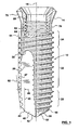
Figure 1 is a side view of an embodiment of a dental implant in accordance with the present invention with a broken away sectional portion. -
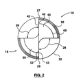
Figure 2 is an end view of the implant ofFigure 1 . -
Figure 1 illustrates a self-drillingdental implant 10. Theimplant 10 comprises abody portion 12 and ahead portion 14. Theimplant 10 has alongitudinal axis 16 which extends from thehead portion 14 to atip portion 18 which is remote from thehead portion 14. Thebody portion 12 comprises thetip portion 18, alead thread portion 20, anintermediate thread portion 22 and adistal thread portion 24. Thedistal thread portion 24 is adjacent thehead portion 14. - The
body portion 12 comprises a pair offlute portions first flute portion 26 is visible inFigure 1 . Thesecond flute portion 28 is partially visible inFigure 2 . - The pitch of the lead thread portion, the intermediate thread portion and the distal thread portion is the same so that as the implant is rotated, the thread will travel along a helical groove cut into the bone.
- The
tip portion 18 is most clearly shown inFigure 2 . Thetip portion 18, includes afirst cutting blade 40 and asecond cutting blade 50. Thefirst cutting blade 40 has acutting edge 42 while thesecond cutting blade 50 has acutting edge 52. One end of thefirst flute portion 26 is adjacent thecutting edge 42 of thefirst cutting blade 40, while one end of thesecond flute portion 28 is located adjacent thecutting edge 52 of thesecond cutting blade 50. Thefirst cutting blade 40 and thesecond cutting blade 50 are arranged substantially symmetrically oppositely opposed about thelongitudinal axis 16 and thecutting edges longitudinal axis 16 to the distal end of the surface of thetip 18. The distal edge of the surface of thetip 18 is illustrated inFigure 2 by thecircle 60. The radially outer end of thecutting edges point Figure 2 . - As the
implant 10 is rotated, when in place against the bone, thecutting edges cutting edges second flute portions Figure 1 , it will be observed that the flute portions represent a relieved portion cut into what is otherwise a substantially cylindrical threaded exterior surface of theimplant 10. Theflute portion 26 illustrated inFigure 1 extends substantially parallel to theaxis 16. Thus, bone chips created by thecutting edge 42 can flow in the distal direction along the flutes. - The
implant 10 is a self-tapping and self drilling implant. Typically, when any type of device is said to be self-tapping, then the device must cut its way into the host site, in this case bone. Either the cut material must be compressed to allow the crests of the thread to pass through the bone, or bone material must be cut away permitting passage of the thread crest. In the case of a wood screw going into soft wood, the wood may be compressed on either side of the crest of the thread permitting the screw to advance into the wood and the crest of the thread to be received in the wood. Significant compression of this type is not acceptable in bone as this is likely to cause injury and in certain cases necrosis at the site of the thread crest. In order to not damage the surface of the bone which is immediately adjacent to the surface of the thread by compression, the cut material must be removed from the installation site. The cut material can be removed only by providing a path out of the installation site which does not generate significant compression of the host material. In theimplant 10, the path for removal of bone cuttings is provided by theflute portions flute portions axis 16. Theflute portions axis 16 along the surface of thelead thread portion 20 and theintermediate thread portion 22. For reasons which will be discussed below, theflute portions intermediate thread portion 22 and do not extend into thedistal thread portion 24. - In order to install the
implant 10, the surgical site may first be prepared for installation of the implant. The implant can be installed by directly engaging the soft tissue with the implant. In more typical situations, an incision will be made in the soft tissue. If desired a profiling drill may be used to create a dimple in the jaw bone at the desired location of theaxis 16. This determines the location of the implant. The implant is then grasped in a tool to be discussed below at thehead portion 14. Pressure in the proximal direction is applied to theimplant 10 and theimplant 10 is rotated. The cutting edges 42 and 52 then begin to remove bone chips from the host bone at the installation site. As the cutting edges create bone chips, the bone chips are forced to flow in the distal direction along theflute portions thread portions - As the implant advances proximally, bone chips can flow into the
flute portions flute portions distal end 30 of theflute portion 26 is visible inFigure 1 . Thesecond flute portion 28 also ends in a distal end which is located axially along theaxis 16 adjacent to and diametrically opposite from theend 30. - As the implant nears its intended installation depth, the
distal end 30 of theflute portion 26 will then be received in the host bone. As shownFigure 1 , thedistal thread portion 24 comprises a few additional revolutions of thread. As shown inFigure 1 , this is approximately 3 revolutions. Thus, theflute portions distal thread portion 24. - In order to facilitate the final flow of bone chips out of the
flute portions - It is desirable that the
fluted portions flute portions flute portions implant 10, the surface of theflute portions axis 16. The distance between the surface of theflute portions flute portions flute portions fluted portions flute portions flute portions - The surface of the
implant 10 other than the surface of theflute portions - From reference to
Figure 1 , it can be appreciated how the implant cuts the aperture in the bone to accommodate the implant and the threaded portion of the implant. The cutting edges 42 and 52 are diagrammatically illustrated inFigure 1 . From reference toFigure 2 , it will be observed that the cutting edges 42 and 52 extend radially outwardly from theaxis 16 to the circumference of the implant adjacent the first revolution of the thread of thelead thread portion 20. The threads of thelead thread portion 20, theintermediate thread portion 22 and thedistal thread portion 24 comprise the usual crest and root. Thelead thread portion 20 comprises three revolutions of the thread. A line indicated at 62 inFigure 1 joins the tips of the crests of the first three revolutions. It will be observed that theline 62 is not parallel to thelongitudinal axis 16. Theline 62 extends radially outwardly in the distal direction relative to theaxis 16, that is, the diameter described by the crest of the thread in thelead thread portion 20 increases in the distal direction from the tip portion. Thus as the implant is rotated, the crest of the thread in the lead portion cuts an increasing diameter until the crest of the thread in theintermediate thread portion 22 is accommodated. Thus, the crest widens the portion of the bone required to accommodate the crest of the thread over the course of the three revolutions of the lead portion of the thread. - From reference to
Figure 2 , it will be noted that the end of the cutting edge radially outwardly from theaxis 16 is given as thepoints points Figure 1 as thepoint 43. Theline 45 illustrated inFigure 1 is a line parallel to theaxis 16 of the implant passing through the outwardlyextremity 43 of thecutting edge 42 and is referred to herein. Theline 47 inFigure 1 , is a line drawn through the roots of a thread in theintermediate portion 22 and thedistal portion 24. Theline 45 is displaced from theaxis 16 by a distance referred to herein as the cutting edge distance. Theline 47 is referred to herein as the root line and the distance of the root line from theaxis 16 is referred to as the root distance. The distance between thelines arrow 49. - The
distance 49 as illustrated inFigure 1 , illustrates the amount of compression that will be applied to the surface of the bone as the implant passes proximally into the bone. The bone is cut away by the cutting edges 42 and 52 leaving a cylindrical hole. Some further cutting action takes place in the bone by the crests of the thread of the lead portion. As the crests of the thread of the lead portion pass any particular point in the bone, the bone is then compressed a total amount as shown by thedistance 49. - The angle of the
line 62, relative to the axis, establishes a rate of compression, that is, the greater the angle between thelines 62 and theaxis 16, the greater will be the speed of compression for a given rotational speed of theimplant 12. The implant may be designed to give any desired rate of compression by including fewer or greater number of revolutions in the lead thread portion. - The
distance 49 between thelines distance 49 may be larger, perhaps up to as large as 1/3 of the radial distance between theaxis 16 and theline 47. However, in more dense bone, the amount of compression that may be satisfactory may be much less, perhaps as little as 5%. As those familiar with this area will be well aware, the jaw bone in a human is composed of areas of quite different density. The back portion of the upper jaw is much softer than the front portion of the lower jaw. In relatively softer or less dense bone, a higher permissible compression amount and a higher permissible rate may be acceptable without damaging the bone. In dense bone however, it is likely that there will be a much lower permissible compression amount and a lower permissible compression rate. - The
intermediate thread portion 22 commences, as shown inFigure 1 , with the crest of the forth revolution of the thread from thetip portion 18. Theline 64 joins the tips of the crests of the thread in theintermediate thread portion 22 and in the distal threadedportion 24. Theline 64 is parallel to theaxis 16. This means that there is no additional cutting required to accommodate the crests of the thread to allow passage of theintermediate thread portion 22 or thedistal thread portion 24 in the host bone. Similarly theroot line 47 joining the roots of the threads in theintermediate thread portion 22 and thedistal thread portion 24 is also parallel to theaxis 16. These two factors mean that there is no further cutting of the bone at a particular location in the bone once thetip portion 18 and thelead thread portion 20 have passed that particular location. - Osseointegration occurs as the host bone grows around and incorporates the surface of the
implant 10. The surface of theentire tip portion 18, thelead thread portion 20, theintermediate thread portion 22 and thedistal thread portion 24 will all be in intimate contact with the host bone. As the self tapping implant passes into the bone, there is no excess space or clearance between the implant and the host bone. The only portion of the implant which is not in close contact with the host bone is that portion represented by the surface of theflute portions flute portions flute portions flute portions distal thread portion 24, then there is circumferential contact all the way around the surface of theimplant 10 adjacent thedistal thread portion 24. The top three revolutions of the thread, that is the thread in thedistal thread portion 24, will be in contact with the superior cortex to provide good engagement at the top of the implant. Most stabilization of the implant occurs in the superior cortex and accordingly, it is desirable to have maximum surface area available for integration. In part, this can be achieved by having theflutes - The
head portion 14 of theimplant 10 comprises a generally cylindricalouter surface 70. The diameter of the generallycylindrical surface 70 may be substantially equal to the diameter of the root of the thread in the intermediate and distal threaded portions. The distal end of thecylindrical surface 70 of thehead 14 merges with an outwardly flaringtapered surface 72. - In
Figure 1 , thehead portion 14 is shown in partial section. Thehead portion 14 comprises aninternal bore 80. Theinternal bore 80 extends generally co-axially with theaxis 16. A proximal portion of thebore 80 may be threaded as indicated at 82. The internal thread indicated at 82 of thebore 80 provides a structure for fixing various other structures to theimplant 10. During the initial healing stage, a healing cap is used to close the distal end of thebore 80. When the implant is used for the support of a prosthesis, the prosthesis may be attached to an abutment. The abutment will have a thread which is complimentary to theinternal thread 82 of thebore 80. - The proximal end of the
bore 80 is shown at 84. FromFigure 1 it will be noted that, preferably thedistal end 30 of theflute 26 is spaced in the proximal direction from theproximal end 84 of thebore 80. The radial depth of theflute 26 might otherwise encroach upon the wall thickness between thebore 80 and the root of thedistal thread portion 24. This in turn might require a bore with a smaller diameter which is not desirable. The radial depth of theflutes - The
implant 10 may be made from any material which is suitable for integration into the body. Typically, this may be metals such as titanium or titanium alloys. However, other materials may be used including stainless steel. - In order to install the implant, the site is prepared for installation. A profiling drill is used to make a small dimple in the bone. The dimple is located at the desired location for the
axis 16 of the implant. The implant may then be gripped by means of a standard dental tool which grasps thehead portion 14 of theimplant 10. Thehead portion 14 of theimplant 10 is grasped to prevent any relative rotation between the installation tool and theimplant 10. Pressure is then applied to the implant in the proximal direction and the tool is used to rotate the implant. When the implant has been positioned to the desired depth, the tool is removed from the head portion of the implant. Thereafter a healing cap is inserted into the head portion of the implant and the surgical site closed temporarily to permit integration of the implant into the host bone. Typically, integration may take 4 to 6 months. Upon integration of the implant, the site may be opened at the distal end and a prosthesis attached to the implant by means of thethreads 82 in theinternal bore 80.
Claims (14)
- A dental implant (10) for installation in a patient's jaw comprising a body portion (12) and a head portion (14), said body portion comprising a tip portion (18) remote from said head portion, said body portion having an external thread including 1) a lead thread portion (20) adjacent said tip portion, 2) an intermediate thread portion (22) adjacent said lead thread portion and 3) a distal thread portion (24), adjacent said head portion, wherein said thread of said lead thread portion, said intermediate thread portion and said distal thread portion comprises a cutting edge so that said implant is self tapping said dental implant further comprising a central bore (80) within said head portion and an internal thread (82) within said bore for receiving a dental prosthesis, and wherein said tip portion comprises at least one cutting edge (42,52) for cutting bone to form an initial bore as said implant is rotated, said body portion comprising at least one flute (26,28), said flute having a first end adjacent said at least one cutting edge (42,52) of the tip portion for assisting removal of bone cuttings from said cutting edge, said body portion haying a longitudinal axis (16) and said at least one cutting edge (42,52) of the tip portion commencing at said axis extending radially outwardly from said axis so that upon rotation of said implant in a patient's jaw said implant cuts the initial bore and cuttings from the initial bore flow into said at least one flute, said implant being self-drilling and self-tapping.
- The dental implant of claim 1 wherein said body portion comprises an outer surface and said at least one flute extends along said outer surface of said body portion in a direction substantially parallel to said axis.
- The dental implant of claim 1 wherein said implant comprises at least two said tip portion cutting edges and at least two said flutes.
- The dental implant of claim 2 wherein said implant comprises two said tip portion cutting edges and two said flutes.
- The dental implant of claim 2 wherein said flute extends from said tip portion along said lead thread portion and said intermediate thread portion of said body portion.
- The dental implant of claim 5 wherein said flute has a distal end and said distal end is adjacent a proximal end of said distal thread portion.
- The dental implant of claim 5 wherein said flute has a flute surface and said surface of said flute is roughened to assist in osseointegration.
- The dental implant of claim 7 wherein the surface of said lead thread portion and the surface of said intermediate thread portion of said body portion are smooth.
- The dental implant of claim 5 wherein said lead thread portion comprises a thread having at least three revolutions.
- The dental implant of claim 9 wherein said thread has a crest and a crest line (62) joining the crest of said three revolutions of said lead thread portion extends radially outwardly, distally, relative to said generally longitudinal axis.
- The dental implant of claim 10 wherein a crest line (64) joining the crest of the thread of said intermediate thread portion and said distal thread portion is substantially parallel to said axis.
- The dental implant of claim 11 wherein said external thread has a root and a root line (47) extending through the root of the thread of said intermediate portion and said distal portion is parallel to said axis and is displaced from said axis a root distance and wherein said at least one tip portion cutting edge extends from said axis radially outwardly to a respective tip portion cutting edge end (43,53) and said tip portion cutting edge end is displaced from said axis, a cutting edge distance (45) and wherein said root distance is greater than said cutting edge distance.
- The dental implant of claim 12 wherein the difference (49) between said root distance and said cutting edge distance is not greater than one third of said root distance.
- The dental implant of claim 13 wherein said difference is not greater than five percent (5%) of said root distance.
Applications Claiming Priority (3)
| Application Number | Priority Date | Filing Date | Title |
|---|---|---|---|
| US10/086,860 US7008227B2 (en) | 2002-03-04 | 2002-03-04 | Self-drilling implant |
| US86860 | 2002-03-04 | ||
| PCT/CA2003/000258 WO2003073956A1 (en) | 2002-03-04 | 2003-02-27 | Self-drilling implant |
Publications (2)
| Publication Number | Publication Date |
|---|---|
| EP1480575A1 EP1480575A1 (en) | 2004-12-01 |
| EP1480575B1 true EP1480575B1 (en) | 2011-10-19 |
Family
ID=27787515
Family Applications (1)
| Application Number | Title | Priority Date | Filing Date |
|---|---|---|---|
| EP03702250A Expired - Lifetime EP1480575B1 (en) | 2002-03-04 | 2003-02-27 | Self-drilling implant |
Country Status (9)
| Country | Link |
|---|---|
| US (1) | US7008227B2 (en) |
| EP (1) | EP1480575B1 (en) |
| JP (1) | JP2005518867A (en) |
| AT (1) | ATE529066T1 (en) |
| AU (1) | AU2003205478B2 (en) |
| CA (1) | CA2478497C (en) |
| ES (1) | ES2373438T3 (en) |
| NZ (1) | NZ535637A (en) |
| WO (1) | WO2003073956A1 (en) |
Cited By (1)
| Publication number | Priority date | Publication date | Assignee | Title |
|---|---|---|---|---|
| DE102021124543A1 (en) | 2021-09-22 | 2023-03-23 | Bego Implant Systems Gmbh & Co. Kg | dental implant |
Families Citing this family (43)
| Publication number | Priority date | Publication date | Assignee | Title |
|---|---|---|---|---|
| SE526745C2 (en) * | 2003-04-17 | 2005-11-01 | Nobel Biocare Ab | Fixture for anchoring in the jawbone |
| US20060110707A1 (en) * | 2004-11-22 | 2006-05-25 | Michael Perez Davidi | Dental implant |
| ITMI20050195A1 (en) * | 2005-02-11 | 2006-08-12 | Aquila Luca Dell | PROSTHETIC INSTALLATION PARTICULARLY FOR ENDOOSSEA IMPLANTOLOGY AND FOR OSTEOINTEGRANT ORTHOPEDICS WITH IMMEDIATE AND DEFERRED LOAD |
| US8277218B2 (en) * | 2005-10-20 | 2012-10-02 | D Alise David D | Screw-type dental implant |
| JP2007135751A (en) * | 2005-11-16 | 2007-06-07 | Gc Corp | Dental implant |
| US8100946B2 (en) | 2005-11-21 | 2012-01-24 | Synthes Usa, Llc | Polyaxial bone anchors with increased angulation |
| US20070122764A1 (en) * | 2005-11-28 | 2007-05-31 | Ace Surgical Supply Co., Inc. | Orthodontic bone screw |
| ES2310071B1 (en) * | 2005-12-13 | 2009-10-21 | Implant Microdent System, S.L. | DENTAL PROTESIS FIXING SYSTEM. |
| US7479010B2 (en) * | 2006-01-09 | 2009-01-20 | Ricardo Levisman | Threaded implant with improved distal end |
| JP3927589B1 (en) * | 2006-01-17 | 2007-06-13 | 酒井精工株式会社 | Rotary cutting tool and method of manufacturing rotary cutting tool |
| ITMI20060512A1 (en) * | 2006-03-21 | 2007-09-22 | Aquila Luca Dell | STRUCTURE FOR PACKAGING AND MANIPULATING AN ENDO-BONE PLANT |
| US20070298374A1 (en) * | 2006-06-27 | 2007-12-27 | Dana Alan Carlton | Apparatus and method for vertical positioning of dental implants |
| US20080187886A1 (en) | 2007-02-07 | 2008-08-07 | Robb T Tait | Dental implant with constant thread crest width |
| KR100842815B1 (en) * | 2007-03-02 | 2008-07-01 | 이경동 | Drill screw for implant operation and level indicator mounted thereto |
| PL2170192T3 (en) * | 2007-07-20 | 2011-07-29 | Synthes Gmbh | Polyaxial bone fixation element |
| US9439681B2 (en) | 2007-07-20 | 2016-09-13 | DePuy Synthes Products, Inc. | Polyaxial bone fixation element |
| KR100940040B1 (en) * | 2007-11-26 | 2010-02-04 | 김수홍 | A tap drill for dental implant |
| EP2095790A1 (en) * | 2008-02-28 | 2009-09-02 | Eugenio Gastaldi | Bio-compatible device for dental bone implantation for anatomical restoration |
| US20090290955A1 (en) * | 2008-05-26 | 2009-11-26 | Yi-Ho Lin | Decorating strip |
| US9282998B2 (en) | 2008-09-05 | 2016-03-15 | DePuy Synthes Products, Inc. | Bone fixation assembly |
| PL2337512T3 (en) | 2008-09-12 | 2012-09-28 | Synthes Gmbh | Spinal stabilizing and guiding fixation system |
| CA2738659A1 (en) | 2008-09-29 | 2010-04-01 | Synthes Usa, Llc | Polyaxial bottom-loading screw and rod assembly |
| CN102202589A (en) | 2008-11-03 | 2011-09-28 | 斯恩蒂斯有限公司 | Uni-planar bone fixation assembly |
| US9848927B2 (en) * | 2009-01-27 | 2017-12-26 | Intra-Lock International, Inc. | Self-clearing self-cutting implant |
| US10105163B2 (en) | 2009-04-15 | 2018-10-23 | DePuy Synthes Products, Inc. | Revision connector for spinal constructs |
| KR20120039622A (en) | 2009-06-17 | 2012-04-25 | 신세스 게엠바하 | Revision connector for spinal constructs |
| IT1398289B1 (en) * | 2009-10-01 | 2013-02-22 | Ornaghi Luigi & C S N C Di Ornaghi Giuseppe Ed Angelo | DENTAL IMPLANTATION WITH IMPROVED OSTEOINTEGRATION CHARACTERISTICS |
| IL201902A (en) | 2009-11-03 | 2012-12-31 | Ben-Zion Karmon | Dental implant |
| CH702192A1 (en) * | 2009-11-04 | 2011-05-13 | New Dent Ag | A ceramic implant. |
| US20110294094A1 (en) * | 2010-06-01 | 2011-12-01 | Mark Moshavi | Implant and method |
| EP2696799B1 (en) * | 2011-04-14 | 2018-05-23 | Dentsply IH AB | A fixture |
| US9687322B2 (en) * | 2012-09-28 | 2017-06-27 | Robert P. Carmichael | Dental implant positioning system |
| EP2931169B1 (en) | 2012-12-11 | 2018-07-18 | Huwais Ip Holding Llc | Condensing implant |
| WO2014142797A1 (en) * | 2013-03-12 | 2014-09-18 | Jean-Pierre Mobasser | Awl-tipped pedicle screw and method of implanting same |
| KR101594095B1 (en) * | 2014-03-05 | 2016-02-15 | 주식회사 이비아이 | Fixture for dental implant to contain blood easily |
| USD816841S1 (en) | 2014-12-15 | 2018-05-01 | Jjgc Industria E Comercio De Materiais Dentarios S/A | Bone implant |
| BR102014031426B1 (en) | 2014-12-15 | 2018-07-24 | Jjgc Ind E Comercio De Materiais Dentarios S/A | implant |
| WO2016108238A1 (en) * | 2014-12-31 | 2016-07-07 | Cortex Dental Implants Industries Ltd | Dental implants having golden ratio |
| AU2017214679B2 (en) | 2016-02-07 | 2021-05-27 | Huwais IP Holding LLC | Anchor screw with condensing attributes |
| BR102016010184B1 (en) | 2016-05-05 | 2020-10-27 | Jjgc Indústria E Comércio De Materiais Dentários S.A. | prosthetic set and process for producing the same |
| US11376050B2 (en) | 2017-06-27 | 2022-07-05 | Medos International Sarl | Bone screw |
| US10772667B2 (en) | 2017-12-22 | 2020-09-15 | Medos International Sarl | Bone screw with cutting tip |
| IT202000026786A1 (en) * | 2020-11-10 | 2022-05-10 | Nodrill S R L | IMPLANTABLE DENTAL IMPLANT WITHOUT PREVENTIVE BONE PERFORATION |
Family Cites Families (24)
| Publication number | Priority date | Publication date | Assignee | Title |
|---|---|---|---|---|
| US3981079A (en) * | 1973-08-23 | 1976-09-21 | Lenczycki Joseph J | Dental implant and method of mounting the same in the jaw bone |
| US4341206A (en) * | 1978-12-19 | 1982-07-27 | Synthes Ag | Device for producing a hole in a bone |
| US5061181A (en) * | 1987-01-08 | 1991-10-29 | Core-Vent Corporation | Dental implant including plural anchoring means |
| US5078607A (en) * | 1987-01-08 | 1992-01-07 | Core-Vent Corporation | Dental implant including plural anchoring means |
| DE3708638A1 (en) * | 1987-03-17 | 1988-09-29 | Grafelmann Hans L | SELF-CUTTING SCREW-IN BONE IMPLANT FOR DENTAL PURPOSES |
| FR2635964A1 (en) * | 1988-09-02 | 1990-03-09 | Poulmaire Francis | System which can be implanted with or without resilience, rotary device for producing the implant housing and method for using the implantable system |
| IL94477A0 (en) | 1990-05-22 | 1991-03-10 | Maarachot Amlach 83 Ltd | Device for performing surgical implants |
| FR2682283B1 (en) * | 1991-10-10 | 1994-01-28 | Gerard Scortecci | DENTAL IMPLANT WITH VERTICAL PENETRATION, DESIGNED TO ADAPT TO DIFFERENT DEGREES OF HARDNESS OF THE BONE. |
| US5435723A (en) * | 1993-08-18 | 1995-07-25 | O'brien; Gary R. | Endosseous dental implant system |
| US5362234A (en) * | 1993-09-21 | 1994-11-08 | Alfred Salazar | Self-drilling endosteal hollow-basket implant system with shock-absorber |
| US5816812A (en) * | 1994-07-22 | 1998-10-06 | Osteomed Corporation | Dental implant fixture |
| US5727943A (en) * | 1995-07-18 | 1998-03-17 | Implant Innovations, Inc. | Self-tapping, screw-type dental implant |
| US5601429A (en) * | 1995-08-11 | 1997-02-11 | Blacklock; Gordon D. | Dental implant anchor |
| SE9600208D0 (en) | 1996-01-19 | 1996-01-19 | Astra Ab | Fixture and prosthesis including the same |
| FR2749756B1 (en) * | 1996-06-14 | 1998-09-11 | Bioland | PROCESS FOR THE PREPARATION OF AN IMPLANTABLE COMPOSITE MATERIAL, MATERIAL OBTAINED, IMPLANT COMPRISING SUCH MATERIAL, AND IMPLEMENTATION KIT |
| US6217331B1 (en) * | 1997-10-03 | 2001-04-17 | Implant Innovations, Inc. | Single-stage implant system |
| BR9806316A (en) * | 1997-10-10 | 2000-03-14 | Beatriz Aldama Bolunburu | Dental implant |
| US5947735A (en) | 1997-11-10 | 1999-09-07 | Sulzer Calcitek Inc. | Surface roughening of self-tapping dental implants |
| US6048204A (en) * | 1998-02-03 | 2000-04-11 | Lifecore Biomedical, Inc. | Self tapping screw type dental implant |
| US6398785B2 (en) * | 1998-04-14 | 2002-06-04 | Joseph Edward Carchidi | Apparatus for rigidly fixing craniomaxillofacial tissue grafts and bone plates |
| SE9802572D0 (en) * | 1998-07-17 | 1998-07-17 | Astra Ab | Dental implant |
| CA2249948C (en) | 1998-10-09 | 2006-04-04 | Donald R. Johnson | Bone implant |
| SE514142C2 (en) | 1999-03-09 | 2001-01-08 | Nobel Biocare Ab | Self-tapping implants |
| AU781809B2 (en) | 2000-09-19 | 2005-06-16 | Eduardo Anitua Aldecoa | Dental implant-carrier assembly |
-
2002
- 2002-03-04 US US10/086,860 patent/US7008227B2/en not_active Expired - Lifetime
-
2003
- 2003-02-27 JP JP2003572481A patent/JP2005518867A/en active Pending
- 2003-02-27 ES ES03702250T patent/ES2373438T3/en not_active Expired - Lifetime
- 2003-02-27 AT AT03702250T patent/ATE529066T1/en not_active IP Right Cessation
- 2003-02-27 NZ NZ535637A patent/NZ535637A/en not_active IP Right Cessation
- 2003-02-27 CA CA2478497A patent/CA2478497C/en not_active Expired - Lifetime
- 2003-02-27 AU AU2003205478A patent/AU2003205478B2/en not_active Expired
- 2003-02-27 EP EP03702250A patent/EP1480575B1/en not_active Expired - Lifetime
- 2003-02-27 WO PCT/CA2003/000258 patent/WO2003073956A1/en active IP Right Grant
Cited By (2)
| Publication number | Priority date | Publication date | Assignee | Title |
|---|---|---|---|---|
| DE102021124543A1 (en) | 2021-09-22 | 2023-03-23 | Bego Implant Systems Gmbh & Co. Kg | dental implant |
| WO2023046622A1 (en) | 2021-09-22 | 2023-03-30 | Bego Implant Systems Gmbh & Co. Kg | Dental implant |
Also Published As
| Publication number | Publication date |
|---|---|
| CA2478497A1 (en) | 2003-09-12 |
| US7008227B2 (en) | 2006-03-07 |
| CA2478497C (en) | 2010-12-14 |
| JP2005518867A (en) | 2005-06-30 |
| WO2003073956A1 (en) | 2003-09-12 |
| US20030165796A1 (en) | 2003-09-04 |
| NZ535637A (en) | 2005-10-28 |
| AU2003205478B2 (en) | 2008-10-09 |
| ATE529066T1 (en) | 2011-11-15 |
| EP1480575A1 (en) | 2004-12-01 |
| ES2373438T3 (en) | 2012-02-03 |
| AU2003205478A1 (en) | 2003-09-16 |
Similar Documents
| Publication | Publication Date | Title |
|---|---|---|
| EP1480575B1 (en) | Self-drilling implant | |
| US5816812A (en) | Dental implant fixture | |
| EP0424734B1 (en) | Screw device for fixing prostheses to bones | |
| US20180078297A1 (en) | Self-clearing self-cutting implant | |
| US6540752B1 (en) | Threaded bone tunnel dilator | |
| US6887077B2 (en) | Immediate load dental implant system and method of use | |
| US20020094508A1 (en) | Rotary osteotome for dental implant | |
| RU2547726C2 (en) | Self-tapping screw implant | |
| CN110831531A (en) | Angled grooves in cannulated bone screws | |
| WO2010088213A2 (en) | Self-clearing self-cutting implant | |
| JP6301949B2 (en) | Condensation implant | |
| TWI745922B (en) | Hollow-point condensing-compaction tool | |
| US20090220914A1 (en) | Dental implant and a method of implantation thereof | |
| JP2022504533A (en) | Dental implant screw | |
| CN111107808B (en) | Dental implant | |
| EP2301475A1 (en) | Dental implant | |
| JP3307950B2 (en) | Self-tapping screw type dental implant | |
| US20150104755A1 (en) | Winged implant | |
| US20080031704A1 (en) | Low Torque Thread Design | |
| US20230404717A1 (en) | A dental implant implantable without a previous perforation of bone |
Legal Events
| Date | Code | Title | Description |
|---|---|---|---|
| PUAI | Public reference made under article 153(3) epc to a published international application that has entered the european phase |
Free format text: ORIGINAL CODE: 0009012 |
|
| 17P | Request for examination filed |
Effective date: 20040917 |
|
| AK | Designated contracting states |
Kind code of ref document: A1 Designated state(s): AT BE BG CH CY CZ DE DK EE ES FI FR GB GR HU IE IT LI LU MC NL PT SE SI SK TR |
|
| AX | Request for extension of the european patent |
Extension state: AL LT LV MK RO |
|
| 17Q | First examination report despatched |
Effective date: 20070326 |
|
| GRAP | Despatch of communication of intention to grant a patent |
Free format text: ORIGINAL CODE: EPIDOSNIGR1 |
|
| RTI1 | Title (correction) |
Free format text: SELF-DRILLING IMPLANT |
|
| GRAS | Grant fee paid |
Free format text: ORIGINAL CODE: EPIDOSNIGR3 |
|
| GRAA | (expected) grant |
Free format text: ORIGINAL CODE: 0009210 |
|
| AK | Designated contracting states |
Kind code of ref document: B1 Designated state(s): AT BE BG CH CY CZ DE DK EE ES FI FR GB GR HU IE IT LI LU MC NL PT SE SI SK TR |
|
| REG | Reference to a national code |
Ref country code: GB Ref legal event code: FG4D |
|
| REG | Reference to a national code |
Ref country code: DE Ref legal event code: R081 Ref document number: 60338808 Country of ref document: DE Owner name: SPITZ TECHNOLOGIES CORP., CA Free format text: FORMER OWNERS: CARMICHAEL, ROBERT P., TORONTO, ONTARIO, CA; SANDOR, GEORGE K. B., SCARBOROUGH, ONTARIO, CA |
|
| REG | Reference to a national code |
Ref country code: CH Ref legal event code: EP |
|
| REG | Reference to a national code |
Ref country code: IE Ref legal event code: FG4D |
|
| REG | Reference to a national code |
Ref country code: DE Ref legal event code: R096 Ref document number: 60338808 Country of ref document: DE Effective date: 20111208 |
|
| REG | Reference to a national code |
Ref country code: CH Ref legal event code: NV Representative=s name: MARKS & CLERK (LUXEMBOURG) LLP |
|
| REG | Reference to a national code |
Ref country code: ES Ref legal event code: FG2A Ref document number: 2373438 Country of ref document: ES Kind code of ref document: T3 Effective date: 20120203 |
|
| REG | Reference to a national code |
Ref country code: NL Ref legal event code: VDEP Effective date: 20111019 |
|
| REG | Reference to a national code |
Ref country code: AT Ref legal event code: MK05 Ref document number: 529066 Country of ref document: AT Kind code of ref document: T Effective date: 20111019 |
|
| PG25 | Lapsed in a contracting state [announced via postgrant information from national office to epo] |
Ref country code: BE Free format text: LAPSE BECAUSE OF FAILURE TO SUBMIT A TRANSLATION OF THE DESCRIPTION OR TO PAY THE FEE WITHIN THE PRESCRIBED TIME-LIMIT Effective date: 20111019 |
|
| PG25 | Lapsed in a contracting state [announced via postgrant information from national office to epo] |
Ref country code: SI Free format text: LAPSE BECAUSE OF FAILURE TO SUBMIT A TRANSLATION OF THE DESCRIPTION OR TO PAY THE FEE WITHIN THE PRESCRIBED TIME-LIMIT Effective date: 20111019 Ref country code: GR Free format text: LAPSE BECAUSE OF FAILURE TO SUBMIT A TRANSLATION OF THE DESCRIPTION OR TO PAY THE FEE WITHIN THE PRESCRIBED TIME-LIMIT Effective date: 20120120 Ref country code: PT Free format text: LAPSE BECAUSE OF FAILURE TO SUBMIT A TRANSLATION OF THE DESCRIPTION OR TO PAY THE FEE WITHIN THE PRESCRIBED TIME-LIMIT Effective date: 20120220 Ref country code: NL Free format text: LAPSE BECAUSE OF FAILURE TO SUBMIT A TRANSLATION OF THE DESCRIPTION OR TO PAY THE FEE WITHIN THE PRESCRIBED TIME-LIMIT Effective date: 20111019 Ref country code: SE Free format text: LAPSE BECAUSE OF FAILURE TO SUBMIT A TRANSLATION OF THE DESCRIPTION OR TO PAY THE FEE WITHIN THE PRESCRIBED TIME-LIMIT Effective date: 20111019 |
|
| PG25 | Lapsed in a contracting state [announced via postgrant information from national office to epo] |
Ref country code: CY Free format text: LAPSE BECAUSE OF FAILURE TO SUBMIT A TRANSLATION OF THE DESCRIPTION OR TO PAY THE FEE WITHIN THE PRESCRIBED TIME-LIMIT Effective date: 20111019 |
|
| PG25 | Lapsed in a contracting state [announced via postgrant information from national office to epo] |
Ref country code: SK Free format text: LAPSE BECAUSE OF FAILURE TO SUBMIT A TRANSLATION OF THE DESCRIPTION OR TO PAY THE FEE WITHIN THE PRESCRIBED TIME-LIMIT Effective date: 20111019 Ref country code: BG Free format text: LAPSE BECAUSE OF FAILURE TO SUBMIT A TRANSLATION OF THE DESCRIPTION OR TO PAY THE FEE WITHIN THE PRESCRIBED TIME-LIMIT Effective date: 20120119 Ref country code: EE Free format text: LAPSE BECAUSE OF FAILURE TO SUBMIT A TRANSLATION OF THE DESCRIPTION OR TO PAY THE FEE WITHIN THE PRESCRIBED TIME-LIMIT Effective date: 20111019 Ref country code: DK Free format text: LAPSE BECAUSE OF FAILURE TO SUBMIT A TRANSLATION OF THE DESCRIPTION OR TO PAY THE FEE WITHIN THE PRESCRIBED TIME-LIMIT Effective date: 20111019 Ref country code: CZ Free format text: LAPSE BECAUSE OF FAILURE TO SUBMIT A TRANSLATION OF THE DESCRIPTION OR TO PAY THE FEE WITHIN THE PRESCRIBED TIME-LIMIT Effective date: 20111019 |
|
| PLBE | No opposition filed within time limit |
Free format text: ORIGINAL CODE: 0009261 |
|
| STAA | Information on the status of an ep patent application or granted ep patent |
Free format text: STATUS: NO OPPOSITION FILED WITHIN TIME LIMIT |
|
| 26N | No opposition filed |
Effective date: 20120720 |
|
| PG25 | Lapsed in a contracting state [announced via postgrant information from national office to epo] |
Ref country code: MC Free format text: LAPSE BECAUSE OF NON-PAYMENT OF DUE FEES Effective date: 20120229 |
|
| REG | Reference to a national code |
Ref country code: DE Ref legal event code: R097 Ref document number: 60338808 Country of ref document: DE Effective date: 20120720 |
|
| REG | Reference to a national code |
Ref country code: IE Ref legal event code: MM4A |
|
| PG25 | Lapsed in a contracting state [announced via postgrant information from national office to epo] |
Ref country code: IE Free format text: LAPSE BECAUSE OF NON-PAYMENT OF DUE FEES Effective date: 20120227 Ref country code: AT Free format text: LAPSE BECAUSE OF FAILURE TO SUBMIT A TRANSLATION OF THE DESCRIPTION OR TO PAY THE FEE WITHIN THE PRESCRIBED TIME-LIMIT Effective date: 20111019 |
|
| PG25 | Lapsed in a contracting state [announced via postgrant information from national office to epo] |
Ref country code: FI Free format text: LAPSE BECAUSE OF FAILURE TO SUBMIT A TRANSLATION OF THE DESCRIPTION OR TO PAY THE FEE WITHIN THE PRESCRIBED TIME-LIMIT Effective date: 20111019 |
|
| PG25 | Lapsed in a contracting state [announced via postgrant information from national office to epo] |
Ref country code: TR Free format text: LAPSE BECAUSE OF FAILURE TO SUBMIT A TRANSLATION OF THE DESCRIPTION OR TO PAY THE FEE WITHIN THE PRESCRIBED TIME-LIMIT Effective date: 20111019 |
|
| PG25 | Lapsed in a contracting state [announced via postgrant information from national office to epo] |
Ref country code: LU Free format text: LAPSE BECAUSE OF NON-PAYMENT OF DUE FEES Effective date: 20120227 |
|
| PG25 | Lapsed in a contracting state [announced via postgrant information from national office to epo] |
Ref country code: HU Free format text: LAPSE BECAUSE OF FAILURE TO SUBMIT A TRANSLATION OF THE DESCRIPTION OR TO PAY THE FEE WITHIN THE PRESCRIBED TIME-LIMIT Effective date: 20030227 |
|
| REG | Reference to a national code |
Ref country code: FR Ref legal event code: PLFP Year of fee payment: 13 |
|
| REG | Reference to a national code |
Ref country code: GB Ref legal event code: 732E Free format text: REGISTERED BETWEEN 20150604 AND 20150610 |
|
| REG | Reference to a national code |
Ref country code: CH Ref legal event code: PCOW Free format text: NEW ADDRESS: PARKKISENRANTA 4A, 90650 OULU (FI) $ ROBERT P. CARMICHAEL, 704E-460 QUEENS QUAY WEST, TORONTO ONTARIO M5V 2Y4 (CA) Ref country code: CH Ref legal event code: PUE Owner name: SPITZ TECHNOLOGIES CORP., CA Free format text: FORMER OWNER: GEORGE K. B. SANDOR, CA |
|
| REG | Reference to a national code |
Ref country code: DE Ref legal event code: R082 Ref document number: 60338808 Country of ref document: DE Representative=s name: MARKS & CLERK (LUXEMBOURG) LLP, LU Ref country code: DE Ref legal event code: R081 Ref document number: 60338808 Country of ref document: DE Owner name: SPITZ TECHNOLOGIES CORP., CA Free format text: FORMER OWNERS: CARMICHAEL, ROBERT P., TORONTO, ONTARIO, CA; SANDOR, GEORGE K. B., SCARBOROUGH, ONTARIO, CA Ref country code: DE Ref legal event code: R082 Ref document number: 60338808 Country of ref document: DE Representative=s name: DF-MP DOERRIES FRANK-MOLNIA & POHLMAN PATENTAN, DE |
|
| REG | Reference to a national code |
Ref country code: ES Ref legal event code: PC2A Owner name: SPITZ TECHNOLOGIES CORP. Effective date: 20151126 |
|
| REG | Reference to a national code |
Ref country code: FR Ref legal event code: CA Effective date: 20160105 Ref country code: FR Ref legal event code: TP Owner name: SPITZ TECHNOLOGIES CORP., CA Effective date: 20160105 |
|
| REG | Reference to a national code |
Ref country code: FR Ref legal event code: PLFP Year of fee payment: 14 |
|
| REG | Reference to a national code |
Ref country code: DE Ref legal event code: R082 Ref document number: 60338808 Country of ref document: DE Representative=s name: DF-MP DOERRIES FRANK-MOLNIA & POHLMAN PATENTAN, DE |
|
| REG | Reference to a national code |
Ref country code: FR Ref legal event code: PLFP Year of fee payment: 15 |
|
| REG | Reference to a national code |
Ref country code: DE Ref legal event code: R008 Ref document number: 60338808 Country of ref document: DE Ref country code: DE Ref legal event code: R039 Ref document number: 60338808 Country of ref document: DE |
|
| REG | Reference to a national code |
Ref country code: FR Ref legal event code: PLFP Year of fee payment: 16 |
|
| REG | Reference to a national code |
Ref country code: DE Ref legal event code: R040 Ref document number: 60338808 Country of ref document: DE |
|
| PGFP | Annual fee paid to national office [announced via postgrant information from national office to epo] |
Ref country code: GB Payment date: 20220106 Year of fee payment: 20 Ref country code: DE Payment date: 20220105 Year of fee payment: 20 Ref country code: CH Payment date: 20220114 Year of fee payment: 20 |
|
| PGFP | Annual fee paid to national office [announced via postgrant information from national office to epo] |
Ref country code: IT Payment date: 20220111 Year of fee payment: 20 Ref country code: FR Payment date: 20220118 Year of fee payment: 20 Ref country code: ES Payment date: 20220304 Year of fee payment: 20 |
|
| REG | Reference to a national code |
Ref country code: DE Ref legal event code: R071 Ref document number: 60338808 Country of ref document: DE |
|
| REG | Reference to a national code |
Ref country code: CH Ref legal event code: PL |
|
| REG | Reference to a national code |
Ref country code: GB Ref legal event code: PE20 Expiry date: 20230226 |
|
| REG | Reference to a national code |
Ref country code: ES Ref legal event code: FD2A Effective date: 20230426 |
|
| PG25 | Lapsed in a contracting state [announced via postgrant information from national office to epo] |
Ref country code: GB Free format text: LAPSE BECAUSE OF EXPIRATION OF PROTECTION Effective date: 20230226 |
|
| PG25 | Lapsed in a contracting state [announced via postgrant information from national office to epo] |
Ref country code: ES Free format text: LAPSE BECAUSE OF EXPIRATION OF PROTECTION Effective date: 20230228 |