EP1480498A2 - Verfahren zum Betreiben einer Lichtanlage - Google Patents
Verfahren zum Betreiben einer Lichtanlage Download PDFInfo
- Publication number
- EP1480498A2 EP1480498A2 EP04009347A EP04009347A EP1480498A2 EP 1480498 A2 EP1480498 A2 EP 1480498A2 EP 04009347 A EP04009347 A EP 04009347A EP 04009347 A EP04009347 A EP 04009347A EP 1480498 A2 EP1480498 A2 EP 1480498A2
- Authority
- EP
- European Patent Office
- Prior art keywords
- command
- ballast
- discharge lamp
- electrodes
- lighting system
- Prior art date
- Legal status (The legal status is an assumption and is not a legal conclusion. Google has not performed a legal analysis and makes no representation as to the accuracy of the status listed.)
- Withdrawn
Links
Images


Classifications
-
- H—ELECTRICITY
- H05—ELECTRIC TECHNIQUES NOT OTHERWISE PROVIDED FOR
- H05B—ELECTRIC HEATING; ELECTRIC LIGHT SOURCES NOT OTHERWISE PROVIDED FOR; CIRCUIT ARRANGEMENTS FOR ELECTRIC LIGHT SOURCES, IN GENERAL
- H05B41/00—Circuit arrangements or apparatus for igniting or operating discharge lamps
- H05B41/14—Circuit arrangements
- H05B41/26—Circuit arrangements in which the lamp is fed by power derived from dc by means of a converter, e.g. by high-voltage dc
- H05B41/28—Circuit arrangements in which the lamp is fed by power derived from dc by means of a converter, e.g. by high-voltage dc using static converters
- H05B41/295—Circuit arrangements in which the lamp is fed by power derived from dc by means of a converter, e.g. by high-voltage dc using static converters with semiconductor devices and specially adapted for lamps with preheating electrodes, e.g. for fluorescent lamps
-
- H—ELECTRICITY
- H05—ELECTRIC TECHNIQUES NOT OTHERWISE PROVIDED FOR
- H05B—ELECTRIC HEATING; ELECTRIC LIGHT SOURCES NOT OTHERWISE PROVIDED FOR; CIRCUIT ARRANGEMENTS FOR ELECTRIC LIGHT SOURCES, IN GENERAL
- H05B47/00—Circuit arrangements for operating light sources in general, i.e. where the type of light source is not relevant
- H05B47/10—Controlling the light source
- H05B47/175—Controlling the light source by remote control
- H05B47/18—Controlling the light source by remote control via data-bus transmission
-
- Y—GENERAL TAGGING OF NEW TECHNOLOGICAL DEVELOPMENTS; GENERAL TAGGING OF CROSS-SECTIONAL TECHNOLOGIES SPANNING OVER SEVERAL SECTIONS OF THE IPC; TECHNICAL SUBJECTS COVERED BY FORMER USPC CROSS-REFERENCE ART COLLECTIONS [XRACs] AND DIGESTS
- Y10—TECHNICAL SUBJECTS COVERED BY FORMER USPC
- Y10S—TECHNICAL SUBJECTS COVERED BY FORMER USPC CROSS-REFERENCE ART COLLECTIONS [XRACs] AND DIGESTS
- Y10S315/00—Electric lamp and discharge devices: systems
- Y10S315/07—Starting and control circuits for gas discharge lamp using transistors
Definitions
- the present invention relates to a method for operating a Lighting system and also on appropriately designed ballasts, Control devices and lighting systems.
- the present invention is more specifically concerned with a lighting system in which contain at least one gas discharge lamp with preheatable electrodes is.
- electrodes can be preheated in order to Improve ignition conditions and the life of the discharge lamp to extend.
- Such a discharge lamp is switched on about a preheating process and subsequent ignition process in the lamp.
- Lighting system also at least one control unit for signaling control at least one ballast connected to the discharge lamp via appropriate commands.
- Lighting systems with a plurality of lamps for generating light are in particular for interior lighting but also in other areas of application common.
- the individual Lamps function-controlled in various ways, especially one and switched off..
- the invention is based on the technical problem, an improved operating method to specify for such a lighting system.
- the invention is directed to such a method in which the control device sends a standby command to the ballast, upon which the Ballast operates the discharge lamp in such a way that it has the electrodes continues to heat when the discharge lamp is not burning, so that the control unit by a switch-on command the discharge lamp, its electrodes are heated, can ignite again without delay by a preheating time.
- the invention is also directed to an appropriately designed one Ballast and control device and one built with such devices Lighting system that is designed for the process.
- the Preheating delay between a start command and the actual light generation can be disadvantageous. This applies in particular the area of stage and effect lighting, but can also be used in others Connections especially in the case of more complex timing schemes be of interest.
- the invention accordingly sees a ready state of the ballast and consequently the discharge lamp in which the electrodes stay heated.
- the further heating takes place at least to the extent that a new start without damaging the lamp and with virtually no time delay is possible.
- This state of readiness is caused by that a standby command provided for this purpose by the control unit the ballast is sent.
- the standby command can on the one hand cause the ballast to issue a subsequent shutdown command not in the sense of a complete switch off but in the sense of a Transitions to the standby state, i.e. the electrodes Non-burning discharge lamp continues to heat.
- the standby command but can also be received when the lamp is switched off and preheating or heating the electrodes until the next switch-on command with a corresponding immediate start.
- the standby command a switch-off command at the same time, that is to a ballast of a burning Discharge lamp sent, whereupon the discharge lamp goes out, however, the electrodes remain heated.
- the invention has the advantage of introducing another Command and a corresponding standby status if required to enable quasi-instantaneous immediate start of discharge lamps in lighting systems.
- the one following the standby command Standby status or electrode heating process is limited in time and is shadowed again if there is no switch-on command after a predetermined time or a renewed further standby command was received is. This can prevent the standby state in the case incorrect control or an unexpected end of operation of the lighting system lasts unnecessarily or even indefinitely.
- This time limit is preferably implemented by the ballast and not by the control unit.
- it can also be provided be queried by the ballast when there is a switch-on command whether the standby state, i.e. the electrode heating process, still ongoing. Then depending on the result of the query in front of a Restart a preheating process or not. Also this query is preferably carried out by the ballast itself, it checks So the state of the lamp operated by him or his own operating state.
- the ready state also before the time limit expires or, if this feature is not provided, ended at all by a standby-off command can be.
- a ballast according to the invention is designed accordingly, that is set up to the readiness command according to the invention in the to respond as described.
- a control device is in turn designed to describe one Being able to send a readiness command sees the relevant one additional command. Furthermore, one according to the invention Lighting system at least one corresponding ballast and at least one Corresponding control unit to in accordance with the described method to be able to work.
- the invention also includes the aspect that the ballasts before installation in the lighting system for the respective ballasts individual codes that can be addressed from the outside in terms of signal technology are provided, these codes are read out during the installation of the lighting system and entered into the controller so that they can be entered through the controller assign the installation positions of the respective ballasts are, the control device the respective control devices respective control addresses for control and the control unit assigns the ballasts controls using the control addresses.
- the invention also relates to a correspondingly produced and commissioned lighting system and finally a manufacturing process for a ballast in which the ballast in a adapted to the invention in terms of signaling from the outside addressable code is provided.
- ballasts are - whether now on its own or as a module with a lamp - with each other in the Principle indistinguishable. Therefore, the installer must, for example, at the Assignment of a ballast address in the control unit via the control unit control the corresponding ballast and actually check it, which lamp or lamps has been switched on. Only about it can the assignment between address and position in the lighting system. This can be the case with larger lighting systems or with several rooms or even Distributed lighting systems can be extremely tedious.
- the invention provides that during the installation of the Lighting system, d. H. during the assembly of the ballast, the code read out, So in some way it is captured along with the To be able to enter the installation position in the control unit.
- the installer can use a written on the ballast Copy the code and a numbered accordingly Create installation plan during programming of the control unit can be used.
- he can also put the code in a file type or read with a barcode reader or in another Record data or electrical way. If now the control unit is programmed, there is already an assignment between the codes of the ballasts and their positions in the lighting system because of the installer this assignment already during the assembly of the ballasts, so too at this point in time with knowledge of the positions of the lighting system Has.
- the control device now only needs to be the respective ballasts Assign control addresses, which could also be the codes themselves and address the ballasts with these control addresses in the future and Taxes.
- ballasts and not lamps although ultimately the lamp operation is to be controlled in the lighting system.
- pure lamps without ballast are not addressable per se. It is assumed that the term ballast here, so to speak Operating devices assigned directly to the lamps means those Devices that only have electrical wiring or other simple electrical devices without their own data function and meaning, connected to the lamps. In this sense it is direct ballasts connected to the lamps.
- the connections between the control unit and the ballasts can be wireless, for example based on radio links.
- lighting system is to be understood and limited very generally here not on lighting in the classic sense, that is, at the beginning mentioned examples of indoor or outdoor lighting with conventional Lamps.
- the term “externally signalable” is also generally understandable and can mean on the one hand that the codes in the ballasts can be read from the outside, so that Control unit or a service device can query which code a ballast Has.
- “Addressable” can also mean that the ballasts are selectable specific to the code, i.e. the corresponding one Ballast "feels addressed” when a control command with the appropriate Code is received.
- the method according to the invention thus has the advantage of a clear and comparative little labor-intensive installation and address assignment.
- these advantages also apply to the correspondingly manufactured and in Commissioned lighting system. Due to their applicability in the described Manufacturing processes also transfer these advantages to the matching ballasts and thus on a manufacturing process for a Ballast in which one in the above manner in an address afflicted Controlled lighting system integrable ballast with one of Provide code that can be addressed externally in terms of signaling in the above sense becomes.
- a preferred embodiment of the invention provides that the codes of the ballasts can be addressed from the outside via cables on the ballasts are which lines the ballasts on the control unit connect. These lines can be used in addition to classic electrical lines however, also optical lines, such as fiber optic lines.
- the codes contained in the ballasts can there preferably in be stored in a semiconductor memory. They can also according to the invention preferably optically readable on the ballast, so for example in the manner described as a barcode print or sticker or as alphanumeric labeling.
- More complex control options for lighting systems are especially in the area the interior lighting, so that the invention is preferred judges this area. Examples are conference and event rooms, Theater and the like
- the lighting system according to the invention can in turn be part of a larger system the control unit can in turn be connected to a building control system connected in the sense of a more general house technology control and be controlled by this system.
- the one with the addressing mentioned associated function commands can of course ultimately through the Building control system generated and only by the lighting system control unit be entered into the lighting system.
- the invention also makes it possible in a particularly simple manner to create an existing one Upgrade lighting system.
- the method according to the invention comprises So also the case that an existing lighting system by adding at least of a ballast expanded and thus in the expanded form will be produced. It is conceivable that the previous smaller one Lighting system was already designed according to the invention, as was the case that by appropriate retrofitting or replacement of the control unit a conventional lighting system with the inventive method is made compatible. The conventional smaller lighting system has then yes already via an address assignment, so that the advantages of the invention used for the present or future expansion levels can be.
- a simple and especially in the case of later troubleshooting, complaints or type of coding of the ballasts advantageous from statistical data acquisition consists of the code date and / or place of manufacture the ballast and / or information about the ballast type connectable lamp type or the number of lamps that can be connected or consists only of this information. Even later Retrofitting software updates in microcontroller controls, for example or when looking for items to be exchanged or checked In this way, system parts can particularly affect the ballasts concerned just be selected.
- the ballast or the control device should preferably in this invention be designed for digital communication, the ballast should be digitally controllable using a communication protocol be and the control device for digital control of a ballast be designed with a communication protocol.
- the ballast should be digitally controllable using a communication protocol be and the control device for digital control of a ballast be designed with a communication protocol.
- DALI digital addressable lighting interface
- the invention provides digital control of the ballast with a second additional communication protocol in front.
- this additional aspect of the invention is that it is special Advantages offers the devices mentioned, the term device in the following both the control device and the ballast according to the invention means to interpret two different communication protocols. In addition to a specified protocol, such as the DALI protocol mentioned, a device according to the invention can then use an additional protocol communicate and exchange further information accordingly.
- the invention has the considerable Advantage that this performance increase without deviating from a predetermined one and possibly widespread in practice or through a certain standardization protocol can be achieved.
- the namely devices continue to remain with the first protocol compatible.
- An additional aspect can be that the second Communication protocol as opposed to one based on manufacturer agreement or in another way standardized first protocol manufacturer-specific or in individual cases even application-specific or customer-specific can be determined and possibly also with less effort or shorter intervals are changed and in particular expanded can.
- the devices according to the invention are of course preferably in combination available.
- the invention is therefore particularly directed to lighting systems, in which both the ballasts and control devices according to the invention are designed.
- advantages are already achieved if only a single device corresponds to the invention or when in a lighting system only the ballasts or control devices or part of the same Invention correspond.
- this results in an expanded retrofittability and additional functions by connecting later Devices according to the invention (control devices for existing ballasts or the other way around).
- the individual devices can be external service device designed for the second communication protocol Read out or reprogram without being restricted by the first protocol to be.
- a ballast according to the invention is preferably equipped that it can independently determine when a control signal is received, to which communication protocol the control signal belongs, and itself can accordingly adjust to an evaluation of this control signal.
- the invention would also be executable so that the ballast by an external signal or a switch on the ballast or in a similar manner from the first to the second communication protocol can be switched or vice versa.
- a control device is in turn preferably equipped that there are drive signals according to the first communication protocol and further control signals in accordance with the second communication protocol can send "at the same time".
- "at the same time” means that sending without switching is done by outside influence, so either actually in parallel, for example on different carrier frequencies, or somehow nested in time, that is, with a change to certain ones Bit numbers or certain command numbers.
- the control device interleaves control signals according to both Communication protocols are sent, the signals being without fixed Alternate the alternation order. The change takes place depending on need. For example, there are commands of the second protocol as required between commands of the first protocol interposed.
- the preferred ballast mentioned above can be used independently assign to the protocols.
- a preferred way of distinguishing between the protocols is that the corresponding command words have different word lengths exhibit.
- the command words preferably have identical ones Start bits to initially enable synchronization or triggering.
- the communication protocols are in their Differentiate stop bits.
- the communication protocols according to the invention are preferred biphasencodiert.
- logical 1 and logical 0 are not correspond to an electrical low or high level or vice versa but a predetermined level change.
- a ascending level step a logical 0 and a falling level step mean a logical 1 and vice versa. This has the advantage of being there of a bit can be clearly recognized. This is supplemented by refer to EP 1 069 690.
- a particular use of the invention is that of the invention Devices using the second, for example manufacturer-specific Communication protocol with regard to defect analysis or operational history Read out and reprogram for maintenance or update to be able to.
- the content of an electronic Memory of a microcontroller control for example, on the number of operating hours or error messages can be read out or with a more current operating software or one to a new one Operating software adapted to the lamp type.
- the following are particularly suitable for the additional communication protocol Comprehensive standby commands and standby-off commands which are not provided for in the DALI protocol.
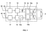
- Fig. 1 shows a schematic block diagram of an inventive Ballast for a discharge lamp in a lighting system.
- the discharge lamp numbered 2 is replaced by the electronic number 1 Ballast started and operated and in particular has preheatable Electrodes on.
- the electronic ballast (hereinafter the For the sake of brevity, the electronic ballast) has on the one hand a mains connection 31 for connection a power supply line 32 and on the other hand a control connection 41 for connecting a control line 42.
- the mains connection 31 leads via a radio protection filter 11 and a rectifier with power factor correction circuit (PFC circuit) to a smoothing capacitor 13, which has an inverter 14, for example with a half-bridge topology, supplied with DC power.
- the inverter 14 essentially contains the function blocks lamp circuit 14a and Heating circuit 14b and is via a transformer 15 with taps for that Heating the electrodes (as indicated graphically) connected to lamp 2.
- control terminal 41 is a digital electronic Interface 17 connected and via this delivers a control signal to one Microcontroller 16 with memory 16a.
- This microcontroller 16 is used for Control of the inverter, d. H. ultimately to control lamp operation including preheating, ignition and dimming function.
- Fig. 2 shows a schematic of an inventive Lighting system, with 1-11 to 1-n and 1-21 to 1-m electronic ballasts of that shown in Fig. 1 Type and with 2-11 to 2-n and 2-21 to 2-m connected to it Discharge lamps corresponding to lamp 2 from FIG. 1 are designated.
- the dashed horizontal line drawn approximately in the middle of FIG. 2 divides symbolically a first room above it from a room below second room. Some of the ECGs and lamps are therefore in the first and another part in the second room. Are in reality Of course, more rooms and, if necessary, further ECGs and lamps are provided, so that you can think of Fig. 2 continued downwards.
- control unit 3a In the left Area are with 7a and 7b controls for operating the lighting system provided, the controls being connected to two control units 3a and 3b are.
- both control units are located in the first room.
- the controls 7a and 7b are also located there top left.
- second control element 7a which is connected to the upper control element 7a and identical Has functions, also in the second room.
- the control unit 3a thus fulfills functions that are operated from both rooms can, while the control unit 3b is only accessible in the first room.
- the control units 3a and 3b have control signal outputs on two bus signal lines 42 connected, the branches of which are shown in Fig. 1 Control line 42 correspond.
- the control signal line 42 is thus Bipolar and designed as a pure bus line because both control units are connected to it 3a and 3b and all electronic ballasts are connected.
- the respective network power supply 32 of the electronic ballasts is not shown in FIG. 2 and takes place according to principles not relevant to the invention. So it's clear that about the controls and controls functions of each Lamps or electronic ballasts can be controlled purely for signaling purposes via a bus line 42 are, with the control signals in more detail becomes.
- Fig. 3 shows an alternative to Fig. 2, with identical reference numerals corresponding Label elements.
- a control unit 3 for entering control commands is used in the control signal line 42, which in turn commands via a bus system in the form of the symbolic line 6 of a more general one Building technology control system receives.
- the control unit 3 here denotes the interface or gateway between the left thereof represented by the line 6 building control system and the actual lighting system starting with the control unit 3.
- the Construction of the building technology control system and in particular the Command input is not shown here; it's just about to demonstrate that the lighting system according to the invention in such a system can be integrated.
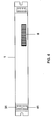
- FIGS. 1-3 shows a concrete example of an electronic ballast 1 according to FIGS. 1-3.
- a cuboid sheet metal housing is shown, in which the with reference to FIG detailed circuit is housed.
- the mains connection can be seen on the left 31 and the control connection 41; on the right are four individual connections drawn for the lamp 2, but not numbered.
- the EVG 1 can over Recesses on the outside left and right are easily fixed in lights become.
- the electronic ballast 1 from FIG. 4 has an imprint 8 with a bar code and an alphanumeric representation of the corresponding code.
- This is the one already explained in the introduction to the description individual coding of the individual ECGs, which the installer at the Installation of the lighting system from Fig. 2 or 3 or when retrofitting the ECGs 1 in an existing lighting system via a barcode reader or through Typing can be recorded.
- the corresponding code is that in FIG. 1 shown semiconductor memory 16a of the microcontroller 16 in the electronic ballast stored. It reflects the place, time and line (in the factory) of the TOE again and can also contain information about the device type, for example about the number of lamp outputs and operable lamp types.
- the installer can now in a correspondingly generated installation plan on paper and / or a corresponding file (read in by a barcode reader or typing in a notebook, for example) between the its installation predetermined position of the individual ECG 1 in the lighting system according to FIG. 2 or FIG. 3 (that is, whether the ECG 1-12 to the discharge lamp 2-12, for example, at the rear right on the ceiling of the first room or around the ECG 1-21 to the discharge lamp 2-21 for example on the hall wall of the second room), and the Codes 8 make an assignment and this database to the programmer the control units 3 available.
- the control unit When programming Now tell the control unit (s) which ECG code 8 which one Position corresponds.
- the corresponding ECG 1 is via the ECG code 8 then addressable in terms of signaling, d. H. responds to commands with the correct code entry or indicates the code on general request the control unit.
- the control unit can therefore the respective electronic ballasts 1 or assign codes to 8 internal control addresses (in principle, also the existing ones) Use codes 8
- 5a and 5b schematically show the word structure (frame) of Control commands between the control units 3 and ECGs 1 according to the two biphase-encoded protocols.
- 5c is the biphase coding encoded protocols. 5c the biphase coding is explained, wherein the left falling edge from the high level to the low level Level of logic 1 and the right complementary rising edge of the should correspond to logical 0.
- the upper protocol 1 corresponds to the DALI protocol already mentioned and consists of a start bit (logical 1) and subsequently 16 information bits No. 15-0 and finally a stop bit which has a high level lasting over two bit lengths (shown as T BIT ) equivalent.
- MSB and LSB stand for the most significant and the least significant bit.
- the second protocol namely an OSRAM-specific one in the present case Communication protocol, drawn in that in the start bit DALI protocol 1 corresponds, however, to a word length extended by one bit and has a stop bit inverse in level.
- the ECGs 1 can both based on the word length as well as on the nature of the stop bit determine whether it is a DALI command or an OSRAM-specific one Command acts.
- FIG. 6 shows one of the various uses of the additional communication protocol, namely with a manufacturer-specific Readiness Command.
- On the left are the meanings of horizontally running Diagram lines entered, with a high level of the line a "switched on” and a low level a “switched off” means. In the diagram shown, it starts from left to right running time thus with the standby mode switched off.
- a filing preheating state follows for a period of time T p , followed by an ignition and thus lamp operation (bottom horizontal line in the diagram jumps to "on").
- a standby command according to the invention (top line jumps to "on") is carried out, which initially does not change the lamp operation itself.
- the following command after an indefinite time, which is not above a certain maximum duration, leads to an end of lamp operation on the one hand, but at the same time, however, to a restart of the filament heating. If a new command follows after a certain time, again not over a certain maximum time, the lamp can, in contrast to the first command (far left), ignite again without having to wait for a new preheating phase T P.
- a new one follows while switched on Readiness command, which in turn leads to a transition to the ready state, So in the filament heating, after the next command and the leads to simultaneous end of lamp operation.
- the standby state i.e. the Filament heating
- the filament heating therefore goes out. consequently As shown on the far right, there must be another one at the next command Filament preheating done.
- the lighting system is thus able to switch on a standby state through the one provided with the second protocol Ready command practically immediately restart the lamp without allowing time delay.
Abstract
Description
- Fig. 1
- zeigt ein schematisches Blockschaltbilds eines erfindungsgemäßen Vorschaltgeräts.
- Fig. 2
- zeigt schematisch eine erfindungsgemäße Lichtanlage.
- Fig. 3
- zeigt ein zweites Ausführungsbeispiel einer erfindungsgemäßen Lichtanlage.
- Fig. 4
- zeigt das Vorschaltgerät aus Fig. 1 von außen.
- Fig. 5a - 5c
- zeigt schematisch den Wortaufbau von Steuerbefehlen gemäß der Erfindung.
- Fig. 6
- zeigt schematische Zeitverlaufsdiagramme zur Erläuterung des erfindungsgemäßen Bereitschaftszustands.
Claims (11)
- Verfahren zum Betreiben einer Lichtanlage, welche aufweist:dadurch gekennzeichnet, dass das Steuergerät (3) an das Vorschaltgerät (1) einen Bereitschaftsbefehl schickt, auf den hin das Vorschaltgerät (1) die Entladungslampe (2) in der Weise betreibt, dass es die Elektroden bei nicht brennender Entladungslampe (2) weiterheizt,Lampen (2) zur Lichterzeugung, davon zumindest eine Gasentladungslampe (2) mit vorheizbaren Elektroden,zumindest ein an die Entladungslampe (2) angeschlossenes Vorschaltgerät (1) undein Steuergerät (3), das das zumindest eine Vorschaltgerät (1) durch signaltechnische Befehle steuern kann,
so dass das Steuergerät (3) durch einen Einschaltbefehl die Entladungslampe (2), deren Elektroden geheizt sind, ohne Verzögerung durch eine Vorheizzeit wieder zünden kann. - Verfahren nach Anspruch 1, bei dem das Vorschaltgerät (1) die Lampe (2) durch den Bereitschaftsbefehl ohne weiteren Befehl abschaltet.
- Verfahren nach Anspruch 1 oder 2, bei dem der auf den Bereitschaftsbefehl folgende Heizvorgang zeitlich begrenzt ist, so dass er abgeschaltet wird, wenn nach einer vorgegebenen Zeit nach dem Bereitschaftsbefehl kein Eirtschaltbefehl oder erneuter Bereitschaftsbefehl ergangen ist.
- Verfahren nach Anspruch 3, bei dem die zeitliche Begrenzung des auf den Bereitschaftsbefehl folgenden Heizvorgangs durch das Vorschaltgerät (1) erfolgt.
- Verfahren nach Anspruch 3 oder 4, bei dem bei einem Einschaltbefehl abgefragt wird, ob der auf den Bereitschaftsbefehl folgende Heizvorgang noch andauert, und, falls dies nicht der Fall ist, vor dem Zünden die Elektroden vorgeheizt werden.
- Verfahren nach Anspruch 5, bei dem die Abfrage durch das Vorschaltgerät (1) erfolgt.
- Verfahren nach einem der vorstehenden Ansprüche, bei dem das Steuergerät (3) den auf den Bereitschaftsbefehl folgenden Heizvorgang durch einen Bereitschafts-Aus-Befehl beenden kann.
- Vorschaltgerät für eine Entladungslampe (2) mit vorheizbaren Elektroden, welches Vorschaltgerät (1) ausgelegt ist für ein Verfahren nach einem der Ansprüche 1 - 7
und dazu, nach Empfang eines Bereitschaftsbefehls eines Steuergeräts (3) die Entladungslampe (2) in der Weise zu betreiben, dass die Elektroden bei nicht brennender Entladungslampe (2) weitergeheizt werden,
so dass das Steuergerät (3) durch einen Einschaltbefehl die Entladungslampe (2), deren Elektroden geheizt sind, ohne Verzögerung durch eine Vorheizzeit wieder zünden kann. - Steuergerät für eine Lichtanlage mit Entladungslampen (2) mit vorheizbaren Elektroden, welches Steuergerät (3) ausgelegt ist für ein Verfahren nach einem der Ansprüche 1 - 7
und dazu, an ein Vorschaltgerät (1) der Entladungslampe (2) einen Bereitschaftsbefehl zu schicken, auf den hin das Vorschaltgerät (1) die Entladungslampe (2) in der Weise betreibt, dass die Elektroden bei nicht brennender Entladungslampe (2) weitergeheizt werden,
so dass das Steuergerät (3) durch einen Einschaltbefehl die Entladungslampe (2), deren Elektroden geheizt sind, ohne Verzögerung durch eine Vorheizzeit wieder zünden kann. - Lichtanlage, ausgelegt für ein Verfahren nach einem der Ansprüche 1 - 7 und mit einem Vorschaltgerät (1) nach Anspruch 8 und einem Steuergerät (3) nach Anspruch 9.
- Lichtanlage nach Anspruch 10, die eine Beleuchtungsanlage für Innenraumbeleuchtung ist.
Applications Claiming Priority (2)
| Application Number | Priority Date | Filing Date | Title |
|---|---|---|---|
| DE10323752A DE10323752A1 (de) | 2003-05-22 | 2003-05-22 | Verfahren zum Betreiben einer Lichtanlage |
| DE10323752 | 2003-05-22 |
Publications (2)
| Publication Number | Publication Date |
|---|---|
| EP1480498A2 true EP1480498A2 (de) | 2004-11-24 |
| EP1480498A3 EP1480498A3 (de) | 2009-05-20 |
Family
ID=33039315
Family Applications (1)
| Application Number | Title | Priority Date | Filing Date |
|---|---|---|---|
| EP04009347A Withdrawn EP1480498A3 (de) | 2003-05-22 | 2004-04-20 | Verfahren zum Betreiben einer Lichtanlage |
Country Status (5)
| Country | Link |
|---|---|
| US (1) | US7075253B2 (de) |
| EP (1) | EP1480498A3 (de) |
| JP (1) | JP2005032709A (de) |
| CA (1) | CA2467609A1 (de) |
| DE (1) | DE10323752A1 (de) |
Cited By (2)
| Publication number | Priority date | Publication date | Assignee | Title |
|---|---|---|---|---|
| CN102316635A (zh) * | 2011-06-29 | 2012-01-11 | 冠捷显示科技(厦门)有限公司 | 一种双色指示灯显示多种工作状态的方法及系统 |
| DE102015217995A1 (de) * | 2015-09-18 | 2017-03-23 | Tridonic Gmbh & Co Kg | Gebäudetechnik-Bussystem mit Zentraleinheit, die dazu eingerichtet ist, Befehle mit unterschiedlichen Frame-Zeitdauern zu übermitteln |
Families Citing this family (13)
| Publication number | Priority date | Publication date | Assignee | Title |
|---|---|---|---|---|
| DE10323690A1 (de) * | 2003-05-22 | 2004-12-09 | Patent-Treuhand-Gesellschaft für elektrische Glühlampen mbH | Lichtanlage und Verfahren zur Herstellung derselben |
| US20070194721A1 (en) * | 2004-08-20 | 2007-08-23 | Vatche Vorperian | Electronic lighting ballast with multiple outputs to drive electric discharge lamps of different wattage |
| DE102004055933A1 (de) * | 2004-11-19 | 2006-05-24 | Patent-Treuhand-Gesellschaft für elektrische Glühlampen mbH | Verfahren zur Vergabe von Kurzadressen in Beleuchtungsanlagen |
| FR2887394B1 (fr) * | 2005-06-17 | 2015-04-17 | Valeo Vision | Procede et dispositif de gestion de ballast notamment pour projecteur de vehicule automobile |
| US7598631B2 (en) * | 2007-01-29 | 2009-10-06 | Fifth Light Technology Ltd. | Addressable power switch |
| US8220957B2 (en) | 2007-02-12 | 2012-07-17 | Abl Ip Holding Llc | Retrofit light assembly |
| DE102007040111B3 (de) * | 2007-08-24 | 2008-10-23 | Siemens Ag | Verfahren zur Inbetriebsetzung eines Beleuchtungssystems |
| US8153894B2 (en) | 2008-04-01 | 2012-04-10 | Abl Ip Holding Llc | Mounting system |
| USD612534S1 (en) | 2008-04-24 | 2010-03-23 | Abl Ip Holding Llc | Bracket |
| USD640825S1 (en) | 2008-04-24 | 2011-06-28 | Abl Ip Holding Llc | Louver |
| US8680969B2 (en) * | 2009-03-20 | 2014-03-25 | Lutron Electronics Co., Inc. | Method of confirming that a control device complies with a predefined protocol standard |
| US20110185349A1 (en) * | 2010-01-28 | 2011-07-28 | Empower Electronics, Inc. | Lamp ballast configured to operate in a self-forming network |
| US20140015416A1 (en) * | 2012-07-11 | 2014-01-16 | Zoltan Somogyvari | Lamp driving module |
Citations (2)
| Publication number | Priority date | Publication date | Assignee | Title |
|---|---|---|---|---|
| US6147463A (en) | 1997-03-04 | 2000-11-14 | Tridonic Bauelemente Gmbh | Electronic ballast for the operation of at least one gas discharge lamp |
| US20020145886A1 (en) | 2001-04-06 | 2002-10-10 | Stevens Carlile R. | Power inverter for driving alternating current loads |
Family Cites Families (12)
| Publication number | Priority date | Publication date | Assignee | Title |
|---|---|---|---|---|
| US5315214A (en) * | 1992-06-10 | 1994-05-24 | Metcal, Inc. | Dimmable high power factor high-efficiency electronic ballast controller integrated circuit with automatic ambient over-temperature shutdown |
| JP3315744B2 (ja) * | 1993-01-25 | 2002-08-19 | 松下電工株式会社 | 調光用放電灯点灯装置 |
| JP2597958Y2 (ja) * | 1993-02-22 | 1999-07-26 | 松下電工株式会社 | 放電灯点灯装置 |
| JPH0765970A (ja) * | 1993-08-26 | 1995-03-10 | Matsushita Electric Works Ltd | 放電灯点灯装置 |
| JP3262428B2 (ja) * | 1993-10-26 | 2002-03-04 | キヤノン株式会社 | 蛍光灯駆動装置 |
| US5691605A (en) * | 1995-03-31 | 1997-11-25 | Philips Electronics North America | Electronic ballast with interface circuitry for multiple dimming inputs |
| JP3861315B2 (ja) * | 1996-04-15 | 2006-12-20 | 松下電工株式会社 | 調光用放電灯点灯装置 |
| JP3890092B2 (ja) * | 1996-04-26 | 2007-03-07 | キヤノン株式会社 | 画像形成装置 |
| WO2001089271A1 (en) * | 2000-05-12 | 2001-11-22 | O2 Micro International Limited | Integrated circuit for lamp heating and dimming control |
| DE10102940A1 (de) * | 2001-01-23 | 2002-08-08 | Patent Treuhand Ges Fuer Elektrische Gluehlampen Mbh | Mikrocontroller, Schaltnetzteil, Vorschaltgerät zum Betrieb mindestens einer elektrischen Lampe und Verfahren zum Betreiben mindestens einer elektrischen Lampe |
| DE10323690A1 (de) * | 2003-05-22 | 2004-12-09 | Patent-Treuhand-Gesellschaft für elektrische Glühlampen mbH | Lichtanlage und Verfahren zur Herstellung derselben |
| DE10323689A1 (de) * | 2003-05-22 | 2004-12-09 | Patent-Treuhand-Gesellschaft für elektrische Glühlampen mbH | Steuerbare Lichtanlage mit zweitem Kommunikationsprotokoll und Geräte hierfür |
-
2003
- 2003-05-22 DE DE10323752A patent/DE10323752A1/de not_active Withdrawn
-
2004
- 2004-04-20 EP EP04009347A patent/EP1480498A3/de not_active Withdrawn
- 2004-05-14 US US10/845,139 patent/US7075253B2/en active Active
- 2004-05-19 CA CA002467609A patent/CA2467609A1/en not_active Abandoned
- 2004-05-20 JP JP2004150836A patent/JP2005032709A/ja active Pending
Patent Citations (2)
| Publication number | Priority date | Publication date | Assignee | Title |
|---|---|---|---|---|
| US6147463A (en) | 1997-03-04 | 2000-11-14 | Tridonic Bauelemente Gmbh | Electronic ballast for the operation of at least one gas discharge lamp |
| US20020145886A1 (en) | 2001-04-06 | 2002-10-10 | Stevens Carlile R. | Power inverter for driving alternating current loads |
Cited By (2)
| Publication number | Priority date | Publication date | Assignee | Title |
|---|---|---|---|---|
| CN102316635A (zh) * | 2011-06-29 | 2012-01-11 | 冠捷显示科技(厦门)有限公司 | 一种双色指示灯显示多种工作状态的方法及系统 |
| DE102015217995A1 (de) * | 2015-09-18 | 2017-03-23 | Tridonic Gmbh & Co Kg | Gebäudetechnik-Bussystem mit Zentraleinheit, die dazu eingerichtet ist, Befehle mit unterschiedlichen Frame-Zeitdauern zu übermitteln |
Also Published As
| Publication number | Publication date |
|---|---|
| JP2005032709A (ja) | 2005-02-03 |
| US7075253B2 (en) | 2006-07-11 |
| DE10323752A1 (de) | 2004-12-09 |
| CA2467609A1 (en) | 2004-11-22 |
| US20040232852A1 (en) | 2004-11-25 |
| EP1480498A3 (de) | 2009-05-20 |
Similar Documents
| Publication | Publication Date | Title |
|---|---|---|
| EP1480495B1 (de) | Lichtanlage und Verfahren zur Herstellung derselben | |
| EP1480496B1 (de) | Steuerbare Lichtanlage mit zweitem Kommunikationsprotokoll und Geräte hierfür | |
| EP1519634B1 (de) | Datenkonverter für eine Beleuchtungsanlage und Verfahren zum Betreiben einer Beleuchtungsanlage | |
| EP1480498A2 (de) | Verfahren zum Betreiben einer Lichtanlage | |
| EP0639938B1 (de) | Steuer-Vorrichtung für gruppenweise zusammengefasste Verbraucher | |
| EP1829429B1 (de) | Verfahren zur programmierung eines betriebsgerätes für leuchtmittel | |
| DE102004039677B4 (de) | Gebäudemanagementsystem und Aktor mit Speicherteil | |
| EP1955578B1 (de) | Steuerungssystem für mehrere verteilt angeordnete verbraucher, insbesondere für lampenbetriebsgeräte, sowie verfahren zur inbetriebnahme | |
| DE10344619B4 (de) | Steuersystem für mehrere verteilt angeordnete Lampenbetriebsgeräte sowie Verfahren zum Initialisieren eines derartigen Steuersystems | |
| EP1292175B1 (de) | Lichtmanagementsystem mit elektronischen Vorschaltgeräten EVG | |
| EP1624729B1 (de) | Verfahren zur Inbetriebnahme eines Beleuchtungssystems und Inbetriebnahmegerät | |
| EP1035755B1 (de) | Verfahren zur Inbetriebnahme der elektrischen Betriebsmittel eines Beleuchtungssystems | |
| EP2359579B1 (de) | Adressierungsverfahren für ein leuchtmittel, insbesondere leuchtdioden | |
| DE202005006465U1 (de) | Lampenbetriebsgerät mit Empfangseinrichtung für externe Steuerbefehle | |
| EP2365737B1 (de) | Zentraler PFC mit DC-Ausgangskreisregelung | |
| EP2745631A2 (de) | Verfahren zur adressierung von leuchtmittelbetriebsgeräten | |
| DE10312183A1 (de) | Gebäudeinstallationssystem | |
| EP2737775A1 (de) | Leuchte mit dmx-betriebsgerät | |
| EP0955740A1 (de) | Studiosteuerungssystem und Verfahren zur Automatiserung von im Studiobereich eingesetzten hebe- und lichttechnischen Geräten | |
| DE102019105344A1 (de) | Verfahren zur Nutzung eines Beleuchtungssystems | |
| EP1699271A2 (de) | Steuersystem für mehrere verteilt anzuordnende Lampenbetriebsgeräte sowie Verfahren zur Inbetriebnahme eines derartigen Steuersystems | |
| DE102012218571A1 (de) | Verfahren und vorrichtung zum zuordnen von netzidentifikationen in einem beleuchtungssystem und beleuchtungssystem |
Legal Events
| Date | Code | Title | Description |
|---|---|---|---|
| PUAI | Public reference made under article 153(3) epc to a published international application that has entered the european phase |
Free format text: ORIGINAL CODE: 0009012 |
|
| AK | Designated contracting states |
Kind code of ref document: A2 Designated state(s): AT BE BG CH CY CZ DE DK EE ES FI FR GB GR HU IE IT LI LU MC NL PL PT RO SE SI SK TR |
|
| AX | Request for extension of the european patent |
Extension state: AL HR LT LV MK |
|
| PUAL | Search report despatched |
Free format text: ORIGINAL CODE: 0009013 |
|
| AK | Designated contracting states |
Kind code of ref document: A3 Designated state(s): AT BE BG CH CY CZ DE DK EE ES FI FR GB GR HU IE IT LI LU MC NL PL PT RO SE SI SK TR |
|
| AX | Request for extension of the european patent |
Extension state: AL HR LT LV MK |
|
| RIC1 | Information provided on ipc code assigned before grant |
Ipc: H05B 41/295 20060101AFI20040903BHEP Ipc: H05B 37/02 20060101ALI20090414BHEP |
|
| 17P | Request for examination filed |
Effective date: 20090619 |
|
| 17Q | First examination report despatched |
Effective date: 20091008 |
|
| AKX | Designation fees paid |
Designated state(s): AT BE BG CH CY CZ DE DK EE ES FI FR GB GR HU IE IT LI LU MC NL PL PT RO SE SI SK TR |
|
| GRAP | Despatch of communication of intention to grant a patent |
Free format text: ORIGINAL CODE: EPIDOSNIGR1 |
|
| INTG | Intention to grant announced |
Effective date: 20180425 |
|
| STAA | Information on the status of an ep patent application or granted ep patent |
Free format text: STATUS: THE APPLICATION IS DEEMED TO BE WITHDRAWN |
|
| RIC1 | Information provided on ipc code assigned before grant |
Ipc: H05B 41/295 20060101AFI20040903BHEP Ipc: H05B 37/02 20060101ALI20090414BHEP |
|
| 18D | Application deemed to be withdrawn |
Effective date: 20180906 |