EP1479411B2 - Apparatus for monitored tumour irradiation - Google Patents
Apparatus for monitored tumour irradiation Download PDFInfo
- Publication number
- EP1479411B2 EP1479411B2 EP03011556A EP03011556A EP1479411B2 EP 1479411 B2 EP1479411 B2 EP 1479411B2 EP 03011556 A EP03011556 A EP 03011556A EP 03011556 A EP03011556 A EP 03011556A EP 1479411 B2 EP1479411 B2 EP 1479411B2
- Authority
- EP
- European Patent Office
- Prior art keywords
- patient
- ray detectors
- ray
- irradiation
- emission
- Prior art date
- Legal status (The legal status is an assumption and is not a legal conclusion. Google has not performed a legal analysis and makes no representation as to the accuracy of the status listed.)
- Expired - Lifetime
Links
Images


Classifications
-
- A—HUMAN NECESSITIES
- A61—MEDICAL OR VETERINARY SCIENCE; HYGIENE
- A61N—ELECTROTHERAPY; MAGNETOTHERAPY; RADIATION THERAPY; ULTRASOUND THERAPY
- A61N5/00—Radiation therapy
- A61N5/10—X-ray therapy; Gamma-ray therapy; Particle-irradiation therapy
- A61N5/1048—Monitoring, verifying, controlling systems and methods
- A61N5/1049—Monitoring, verifying, controlling systems and methods for verifying the position of the patient with respect to the radiation beam
- A61N2005/1061—Monitoring, verifying, controlling systems and methods for verifying the position of the patient with respect to the radiation beam using an x-ray imaging system having a separate imaging source
-
- A—HUMAN NECESSITIES
- A61—MEDICAL OR VETERINARY SCIENCE; HYGIENE
- A61N—ELECTROTHERAPY; MAGNETOTHERAPY; RADIATION THERAPY; ULTRASOUND THERAPY
- A61N5/00—Radiation therapy
- A61N5/10—X-ray therapy; Gamma-ray therapy; Particle-irradiation therapy
- A61N2005/1085—X-ray therapy; Gamma-ray therapy; Particle-irradiation therapy characterised by the type of particles applied to the patient
- A61N2005/1087—Ions; Protons
Definitions
- the present invention relates to a device for monitored tumor irradiation according to the preamble of claim 1.
- Particle therapy is mainly used to treat localized forms of cancer.
- an atomic particle i. an electron, proton, neutron or heavy ion, or X-ray emitted from a jet delivery device to a particular target area in the patient, also referred to as the target volume.
- the particles release energy to the body cells within the target area, destroying them due to the formation of free radicals in the cell fluid.
- irradiation which has been found to be particularly efficient in recent years is irradiation with protons which release most of the energy in a so-called Bragg peak just before their final stopping, so that deeper tumors can be irradiated without the surrounding To severely damage tissue.
- the protons can be directed into the body in such a way that they come to a standstill exactly in the target volume of the tumor and deliver there the majority of their energy to the diseased cells.
- An existing proton therapy facility is integrated with the Loma Linda University Medical Center and is more detailed in the US 4,870,287 described.
- gantries For irradiations of tumors within the human body called gantries, one shown in Fig. 1 , used.
- Such gantries 100 are large, rotatably mounted, ring and / or hollow cylinder structures used to direct the beam of a particle beam fed through a beam delivery unit 101 and having a patient positioning device 102 in its interior on which the patient is irradiated.
- the proton beam delivery device 103 can be rotated 360 ° around the patient with the ring of the gantry 104, without any impairment of the proton beam passing through the beam guide 105.
- the patient can be irradiated from different sides, which allows accurate scanning of the three-dimensional shape of the tumor tissue and protects the surrounding tissue even more.
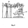
- stationary proton beam dispensers For eye irradiation, stationary proton beam dispensers (see Fig. 2 ), which also have a jet delivery device 107 and a patient positioning device 108, usually a seat.
- the patient be positioned very accurately relative to the proton beam delivery device so that the target volume is optimally targeted. If misplaced, the proton beam would deliver the most energy to and destroy healthy cells within the patient's body.
- the position of the target volume with respect to one or more fixed points within the body of the patient is determined in advance.
- the patients are fixed on a specially prepared patient positioning device. This can either be a couch adapted to the body shapes with corresponding depressions, or a specially adapted treatment chair for eye irradiation.
- the fixed points are usually chosen on the skeletal structure of the patient, in mobile body parts such. Eyes can also be artificial fixed points, such as metal clips, used in the sclera of the eye and serve as a reference system.
- the position of the target volume is then determined, for example, by a combination of conventional nuclear spin and CT scans and localized in the reference system described above.
- a treatment plan for the patient is also created (see eg US 5,117,829 ).
- the treatment plan is calculated by a computer simulation, in particular the number of exposures and the angles at which the rays best reach the cancer cells.
- the patient eventually receives periodic treatments over several days, in which the target volume is repeatedly irradiated with a proton beam.
- the patients are again fixed on the same patient positioning device.
- the irradiation unit should be able to re-determine the reference points in the human body, with reference to which one had previously located the tumor. At these points you can see if the patient is in the right position for which the treatment plan has been developed. For this purpose, several methods have been proposed so far.
- an X-ray image can be recorded before the treatment, and if the fixed points do not coincide
- the patient can be easily moved or the adjustment mechanism provided in the gantry can be easily adjusted so that the position of the patient is completely identical to the position in which the images were taken which had been used to determine the treatment plan.
- such a device has the great disadvantage that X-ray images can be taken only from one direction, so that in unfavorable position of the tumor, the bony skeletal structure and thus the fixed points are often not clearly visible.
- the mechanism used to introduce the movable X-ray source into the proton beam path is relatively complicated and prone to failure.
- EP 1 121 957 A2 Another form of patient position control is in EP 1 121 957 A2 proposed.
- the irradiation unit is provided with a nuclear spin unit which provides noninvasive localization of the tumor almost simultaneously to the irradiation.
- this method is very accurate, it is subject to the spatial limitations that are necessary for a magnetic resonance imaging, so that, for example, a radiation in a gantry is excluded from the outset.
- patient position control is from the WO 00/59575 in which a plurality of position detector arrangements are provided within a gantry, each measuring the distance between the front surface of the position sensor and an opposite surface of the patient.
- a plurality of position detector arrangements are provided within a gantry, each measuring the distance between the front surface of the position sensor and an opposite surface of the patient.
- such a method only measures the surface of the patient and can not provide information for the relative positioning of target volume and reference system.
- US 5,207,223 describes a device for irradiation of tumor tissue in the head area by means of photons.
- the device has a therapy beam dispenser which is arranged in a rotatable gantry, two orthogonally arranged X-ray sources as well as opposite X-ray detectors which serve for the position verification of the patient or of the tumor tissue to be irradiated.
- the two x-ray sources are located laterally from the therapy beam delivery device
- US 6,307,914 also describes a device for irradiating tumor patients by means of photons or other suitable types of radiation.
- X-ray sources and opposing X-ray detectors are also provided, which can be arranged almost anywhere in the room.
- WO 03/018133 A1 and WO 03/018132 A1 show an irradiation device by means of photons, which can also be designed as a gantry-like arrangement. It is mentioned here that the X-ray detectors serving for position verification have an angle of between 20 ° and 60 ° to the beam device, preferably between 30 ° and 45 °. This is to ensure that they do not affect each other and the supplied image has sufficient accuracy.
- the present invention is therefore an object of the invention to provide a device for the monitored tumor irradiation, which is used in Gantrys, relatively simple and easy to maintain, and with the regardless of the direction of radiation, from which the charged particles are directed to the patient, any time accurate and secure positioning of the patient is possible.
- the device according to the invention it is ensured that a reliable assessment of the patient's position can be made at any time and independently of the beam direction of the charged particles.
- the construction of the jet dispenser can be simplified and the quality of the particle beam can be improved by shortening the air paths.
- a determination of the patient position is ensured from multiple sides, wherein the X-ray detectors are in the zone of lowest scattered radiation intensity of the particle radiation, so that irradiation and position verification can be carried out simultaneously.
- the X-ray detectors are arranged at the same distance on both sides of the jet dispenser, which provides mechanical advantages.
- the X-ray detectors include an angle of between 70 ° and 90 °.
- An approximation to 90 ° provides a broad range of information, while a smaller angle is sometimes easier to implement constructively.
- the device for patient positioning is preferably rotatable.
- Fig. 3 a cross-section through an inventive device for the monitored tumor irradiation of cancer patients according to the present invention is shown.
- the device 1 is arranged within a gantry 3, as it is already known from the prior art.
- a preferably movable patent positioning device 5 here designed as a couch, which has suitable immobilization means, for example a recess adapted to the patient in the couch and other means known from the prior art.
- a proton beam delivery device 7 is arranged, which can be moved with the gantry 3 360 ° around the patient around to ensure a radiation from all directions.
- a jet dispenser 7 for other charged particles can be used within the scope of the invention.
- the proton beam delivery device 7 has at its front end a Nozzle 9, which serves for the application of the beam to the patient.
- the beam has a predetermined intensity according to the treatment plan and is deflected by computer-controlled magnets (not shown) so as to enable accurate scanning of the tumor tissue with the particle beam.
- the device for position verification consists in the illustrated example case of two X-ray sources 11, which are aligned in the direction of the patient couch 5 out, and two arranged on the other side of the device for patient positioning 5 X-ray detectors 13, which are suitable, transmitted by the X-rays information in image information convert.
- the X-ray sources 11 preferably have a small focal spot and are briefly pulsed, while 13 are used as X-ray detector 13 flat panels made of amorphous silicon. These panels have in the illustrated embodiment, a detection area of about 30 x 40 cm.
- the X-ray sources 11 are permanently installed in the Gantryring 3, so that they are automatically rotated with each movement of the Gantrys. Also, the X-ray detectors 13 are connected via a suitable mechanism with the housing of the proton beam dispenser 7.
- the X-ray sources 11 and X-ray detectors 13 are conceivable, which provide the advantages according to the invention, but an arrangement of the X-ray detectors 13 is important retrograde to the beam direction of the proton beam.
- the angle between the two X-ray detectors 13 should not be too small to be able to record a sufficient angular range, which increases the security in the position control, because then in any position of the proton beam dispenser 7 a reliable statement about the position of the patient can be taken ,
- the angle between the two X-ray detectors 13 should preferably not be less than 60 °, although an angle of more than 120 ° is possible, but due to the scattering radiation occurring during the proton irradiation is not suitable for a simultaneous use of irradiation apparatus and position verification device since The X-ray detectors 13 would then no longer be in the zone of lowest scattered radiation intensity.
- Particularly preferred is an arrangement of the X-ray detectors at an angle of about 70 °, whereby up to a
- the use of the device according to the invention for monitored tumor irradiation now proceeds as follows: First, the patient is placed on the table ready for him in the gantry.
- the Cartesian summation images determined from the data from the preceding CT examinations, which were calculated to determine the image axes of the X-ray sources and were corrected in perspective, yield a reference image ("DRR": digitally reconstructed radiograph), from which it can be seen how certain fixed points of the bony Skeletons must be arranged when the patient is in the correct position.
- DRR digitally reconstructed radiograph
- the proton beam delivery device 7 When the patient is in the ideal position, it is irradiated by the proton beam delivery device 7, scanning the tumor in a raster scan procedure. The protons release their energy within the tumor tissue and destroy it. In short radiation pauses or even during the irradiation, further X-ray pulses can be emitted from the X-ray sources 11, so that the device according to the invention can also be used for on-line control if it is equipped with a suitable X-ray source Computer system is connected. Then it is possible to use the system for a quasi-continuous continuous monitoring, which automatically terminates the irradiation process when irregularities occur. Since the X-ray detectors 13 are arranged retrograde to the proton beam direction, the images supplied by the X-ray detectors 13 are disturbed by stray radiation resulting from the proton irradiation.
Abstract
Description
Die vorliegende Erfindung betrifft eine Vorrichtung zur überwachten Tumorbestrahlung gemäß dem Oberbegriff des Anspruchs 1.The present invention relates to a device for monitored tumor irradiation according to the preamble of claim 1.
Teilchenstrahlentherapie wird hauptsächlich verwendet, um lokalisierte Formen von Krebs zu behandeln. Üblicherweise wird ein atomares Partikel, d.h. ein Elektron, Proton, Neutron oder Schwerion, oder Röntgenstrahlung aus einer Strahlabgabevorrichtung auf einen speziellen Zielbereich im Patienten emittiert, der auch als Targetvolumen bezeichnet wird. Die Partikel geben Energie an die Körperzellen innerhalb des Zielbereichs ab, wodurch diese aufgrund von Radikalbildung in der Zellflüssigkeit zerstört werden.Particle therapy is mainly used to treat localized forms of cancer. Usually, an atomic particle, i. an electron, proton, neutron or heavy ion, or X-ray emitted from a jet delivery device to a particular target area in the patient, also referred to as the target volume. The particles release energy to the body cells within the target area, destroying them due to the formation of free radicals in the cell fluid.
Eine Bestrahlungsform, die sich in den letzten Jahren als besonders effizient herausgestellt hat, ist die Bestrahlung mit Protonen, welche die meiste Energie in einem sogenannten Bragg-Peak unmittelbar vor ihrem endgültigen Abstoppen abgeben, so daß auch tieferliegende Tumore bestrahlt werden können, ohne das umliegende Gewebe stark zu schädigen. Durch Auswahl der Energie des Protonenstrahls können die Protonen derart in den Körper geleitet werden, daß sie genau im Targetvolumen des Tumors zum Stillstand kommen und dort den Hauptteil ihrer Energie an die kranken Zellen abgeben. Eine bereits in Betrieb befindliche Protonentherapieanlage ist im Loma Linda University Medical Center integriert und detaillierter in der
Für Bestrahlungen von Tumoren innerhalb des menschlichen Körpers werden sogenannte Gantries, eines dargestellt in
Für Augenbestrahlungen können ortsfeste Protonenstrahlabgabevorrichtungen (siehe
Wie erwähnt liefert Protonentherapie einige signifikante klinische Vorteile gegenüber anderen Arten von Therapien, allerdings ist es äußerst wichtig, daß der Patient im Verhältnis zur Protonenstrahlabgabevorrichtung sehr genau positioniert wird, so daß das Targetvolumen optimal getroffen wird. Bei falscher Positionierung würde der Protonenstrahl die meiste Energie an gesunde Zellen innerhalb des Körpers des Patienten abgeben und diese zerstören. Um dies zu verhindern, wird im Vorfeld die Position des Targetvolumens im Hinblick auf einen oder mehrere Fixpunkte innerhalb des Körpers des Patienten bestimmt. Hierzu werden die Patienten auf einer speziell angefertigten Patientenpositionierungsvorrichtung fixiert. Dies kann entweder eine an die Körperformen angepaßte Liege mit entsprechenden Vertiefungen sein, oder ein speziell einzustellender Behandlungsstuhl bei der Augenbestrahlung. Die Fixpunkte werden üblicherweise an der Skelettstruktur des Patienten gewählt, bei beweglichen Körperteilen wie z.B. Augen können auch künstliche Fixpunkte, etwa Metallclips, in die Sklera des Auges eingesetzt werden und als Referenzsystem dienen.As mentioned, proton therapy provides some significant clinical advantages over other types of therapies, however, it is extremely important that the patient be positioned very accurately relative to the proton beam delivery device so that the target volume is optimally targeted. If misplaced, the proton beam would deliver the most energy to and destroy healthy cells within the patient's body. To prevent this, the position of the target volume with respect to one or more fixed points within the body of the patient is determined in advance. For this purpose, the patients are fixed on a specially prepared patient positioning device. This can either be a couch adapted to the body shapes with corresponding depressions, or a specially adapted treatment chair for eye irradiation. The fixed points are usually chosen on the skeletal structure of the patient, in mobile body parts such. Eyes can also be artificial fixed points, such as metal clips, used in the sclera of the eye and serve as a reference system.
Die Position des Targetvolumens wird dann beispielsweise durch eine Kombination von üblichen Kernspin- und CT-Aufnahmen bestimmt und im oben beschriebenen Referenzsystem lokalisiert. Unter Verwendung der Daten des CT-Scans wird auch ein Behandlungsplan für den Patienten erstellt (siehe z.B.
Üblicherweise erhält der Patient schließlich über mehrere Tage hinweg periodische Behandlungen, bei denen das Targetvolumen wiederholt mit einem Protonenstrahl bestrahlt wird. Um sicher zu stellen, daß der Patient bei jeder Behandlung richtig positioniert ist, werden die Patienten wieder auf derselben Patientenpositionierungsvorrichtung fixiert. Um jede Abweichung vom Sollzustand auszuschließen und Positionskorrekturen vornehmen zu können, sollte die Bestrahlungseinheit in der Lage sein, die Referenzpunkte im menschlichen Körper, unter Bezugnahme auf die man den Tumor zuvor lokalisiert hatte, wieder zu bestimmen. An diesen Punkten läßt sich erkennen, ob sich der Patient in der richtigen Position befindet, für die der Bestrahlungsplan entwickelt wurde. Hierfür sind bislang mehrere Verfahren vorgeschlagen worden.Typically, the patient eventually receives periodic treatments over several days, in which the target volume is repeatedly irradiated with a proton beam. To ensure that the patient is properly positioned for each treatment, the patients are again fixed on the same patient positioning device. To be able to exclude any deviation from the nominal state and to be able to make position corrections, the irradiation unit should be able to re-determine the reference points in the human body, with reference to which one had previously located the tumor. At these points you can see if the patient is in the right position for which the treatment plan has been developed. For this purpose, several methods have been proposed so far.
Zum einen wurde vorgeschlagen, mittels einer üblichen Röntgenanordnung ein Bild des sich in der Patientenpositionierungsvorrichtung befindlichen Patienten aufzunehmen, um die Lage der Fixpunkte mit der gewünschten Lage zu vergleichen. Ein derartiges System ist beispielsweise aus der
Eine weitere Form der Patientenpositionskontrolle wird in
Eine weitere Form der Patientenpositionskontrolle ist aus der
Die WO 03/018133 A1 und die WO 03/018132 A1 zeigen eine Bestrahlungsvorrichtung mittels Photonen, die auch als Gantry-artige Anordnung ausgestaltet sein kann. Hierbei ist erwähnt, dass die zur Positionsverifizierung dienenden Röntgenstrahlendetektoren einen Winkel von zwischen 20° und 60° zur Strahlvorrichtung aufweisen, vorzugsweise zwischen 30° und 45°. Dadurch soll gewährleistet sein, dass sie sich nicht gegenseitig beeinflussen und die gelieferte Abbildung eine ausreichende Genauigkeit besitzt.WO 03/018133 A1 and WO 03/018132 A1 show an irradiation device by means of photons, which can also be designed as a gantry-like arrangement. It is mentioned here that the X-ray detectors serving for position verification have an angle of between 20 ° and 60 ° to the beam device, preferably between 30 ° and 45 °. This is to ensure that they do not affect each other and the supplied image has sufficient accuracy.
Der vorliegenden Erfindung liegt daher die Aufgabe zugrunde, eine Vorrichtung zur überwachten Tumorbestrahlung zu schaffen, die in Gantrys einsetzbar, relativ einfach aufgebaut und wartungsfreundlich ist, und mit der unabhängig von der Strahlungsrichtung, aus der die geladenen Teilchen auf den Patienten gerichtet werden, jederzeit eine exakte und sichere Positionsbestimmung des Patienten möglich ist.The present invention is therefore an object of the invention to provide a device for the monitored tumor irradiation, which is used in Gantrys, relatively simple and easy to maintain, and with the regardless of the direction of radiation, from which the charged particles are directed to the patient, any time accurate and secure positioning of the patient is possible.
Diese Aufgabe wird durch die Merkmale des Anspruchs 1 gelöst.This object is solved by the features of claim 1.
Durch die erfindungsgemäße Vorrichtung wird gewährleistet, daß jederzeit und unabhängig von der Strahlrichtung der geladenen Teilchen eine sichere Einschätzung der Patientenposition vorgenommen werden kann. Außerdem kann mit der vorliegenden Erfindung die Konstruktion der Strahlabgabevorrichtung vereinfacht und durch Verkürzung der Luftwege die Qualität des Partikelstrahls verbessert werden.By means of the device according to the invention it is ensured that a reliable assessment of the patient's position can be made at any time and independently of the beam direction of the charged particles. In addition, with the present invention, the construction of the jet dispenser can be simplified and the quality of the particle beam can be improved by shortening the air paths.
Außerdem wird eine Bestimmung der Patientenposition von mehreren Seiten gewährleistet, wobei sich die Röntgenstrahlendetektoren in der Zone niedrigster Streustrahlungsintensität der Teilchenstrahlung befinden, so daß Bestrahlung und Positionsverifizierung gleichzeitig durchgeführt werden können.In addition, a determination of the patient position is ensured from multiple sides, wherein the X-ray detectors are in the zone of lowest scattered radiation intensity of the particle radiation, so that irradiation and position verification can be carried out simultaneously.
Vorzugsweise sind die Röntgenstrahlendetektoren im selben Abstand auf beiden Seiten der Strahlabgabevorrichtung angeordnet, was mechanische Vorteile liefert.Preferably, the X-ray detectors are arranged at the same distance on both sides of the jet dispenser, which provides mechanical advantages.
Bevorzugt schließen die Röntgenstrahlendetektoren einen Winkel von zwischen 70° und 90° ein. Eine Annäherung an 90° liefert ein breites Informationsspektrum, während ein kleinerer Winkel manchmal konstruktiv einfacher umzusetzen ist.Preferably, the X-ray detectors include an angle of between 70 ° and 90 °. An approximation to 90 ° provides a broad range of information, while a smaller angle is sometimes easier to implement constructively.
Es ist mechanisch von Vorteil, daß die Röntgenstrahlendetektoren an der Strahlabgabevorrichtung befestigt sind.It is mechanically advantageous that the X-ray detectors are attached to the jet dispenser.
Für eine leichtere Positionskorrektur ist die Vorrichtung zur Patientenpositionierung vorzugsweise drehbar ausgebildet.For easier position correction, the device for patient positioning is preferably rotatable.
Weitere Einzelheiten, Merkmale und Vorteile der vorliegenden Erfindung ergeben sich aus der nachfolgenden Beschreibung unter Bezugnahme auf die Zeichnungen. Darin zeigt:
- Fig. 1
- ein Gantrysystem nach dem Stand der Technik,
- Fig. 2
- ein Augenbestrahlungssystem nach dem Stand der Technik, und
- Fig. 3
- einen Schnitt durch eine erfindungsgemäße Vorrichtung zur überwachten Tumorbestrahlung in einem Gantry.
- Fig. 1
- a gantry system according to the prior art,
- Fig. 2
- an eye irradiation system according to the prior art, and
- Fig. 3
- a section through a device according to the invention for the monitored tumor irradiation in a gantry.
In
Die Vorrichtung zur Positionsverifizierung besteht im dargestellten Beispielsfall aus zwei Röntgenstrahlenquellen 11, die in Richtung zur Patientenliege 5 hin ausgerichtet sind, und zwei auf der anderen Seite der Vorrichtung zur Patientenpositionierung 5 angeordneten Röntgenstrahlendetektoren 13, die geeignet sind, die durch die Röntgenstrahlen übermittelten Informationen in Bildinformationen umzuwandeln. Die Röntgenstrahlungsquellen 11 weisen vorzugsweise einen kleinen Brennfleck auf und sind kurz gepulst, während als Röntgenstrahlendetektor 13 Flatpanels aus amorphem Silizium eingesetzt werden. Diese Panels besitzen im dargestellten Ausführungsbeispiel eine Detektionsfläche von ca. 30 x 40 cm. Die Röntgenstrahlungsquellen 11 sind fest im Gantryring 3 installiert, so daß sie bei jeder Bewegung des Gantrys automatisch mitgedreht werden. Auch die Röntgenstrahlendetektoren 13 sind über eine geeignete Mechanik mit dem Gehäuse der Protonenstrahlabgabevorrichtung 7 verbunden.The device for position verification consists in the illustrated example case of two
Es sind viele Anordnungen der Röntgenstrahlungsquellen 11 und Röntgenstrahlendetektoren 13 denkbar, welche die erfindungsgemäßen Vorteile liefern, wichtig ist jedoch eine Anordnung der Röntgenstrahlendetektoren 13 retrograd zur Strahlrichtung des Protonenstrahls. Der Winkel zwischen den beiden Röntgenstrahlendetektoren 13 sollte außerdem nicht zu klein sein, um noch einen ausreichenden Winkelbereich aufnehmen zu können, was die Sicherheit bei der Positionskontrolle erhöht, weil dann in jeder Position der Protonenstrahlabgabevorrichtung 7 eine gesicherte Aussage über die Lage des Patienten getroffen werden kann. Hierzu sollte der Winkel zwischen den beiden Röntgenstrahlendetektoren 13 vorzugsweise nicht kleiner als 60° sein, wobei ein Winkel von über 120° zwar möglich ist, aber aufgrund der auftretenden Streustrahlung während der Protonenbestrahlung nicht für einen gleichzeitigen Einsatz von Bestrahlungsapparat und Positionsverifizierungsvorrichtung geeignet ist, da sich die Röntgenstrahlendetektoren 13 dann nicht mehr in der Zone niedrigster Streustrahlungsintensität befinden würden. Besonders bevorzugt ist eine Anordnung der Röntgenstrahlendetektoren unter einem Winkel von ca. 70°, wobei bis zu einem Bereich von ca. 90° ideale Ergebnisse erzielt werden können.Many arrangements of the
Der Einsatz der erfindungsgemäßen Vorrichtung zur überwachten Tumorbestrahlung läuft nun folgendermaßen ab: Zunächst wird der Patient auf den für ihn vorgefertigten Tisch im Gantry gelegt. Die aus den Daten der vorangegangenen CT-Untersuchungen ermittelten kartesianischen Summationsbilder, die zur Bestimmung der Bildachsen der Röntgenstrahlenquellen errechnet und dabei perspektivisch korrigiert wurden, liefern ein Referenzbild ("DRR": digitally reconstructed radiograph), aus dem ersichtlich ist, wie bestimmte Fixpunkte des knöchernen Skeletts angeordnet sein müssen, wenn der Patient in der richtigen Position liegt. Nunmehr wird über zumindest eine der Röntgenstrahlungsquellen 11 Röntgenstrahlung emittiert, die durch den auf der Liege 5 befindlichen Patienten teilweise hindurchtritt und von mindestens einem Röntgenstrahlendetektor 13 detektiert wird. Dieser wandelt die erhaltenen Informationen in Bildinformationen um, welche hierauf entweder manuell oder durch eine geeignete Computersoftware mit dem berechneten Bild verglichen werden können. Für etwaige Korrekturen kann entweder der Patient selbst bewegt werden, oder der Patiententisch 5 wird im Raum gedreht, um geringe Unregelmäßigkeiten auszugleichen. Auch eine Bewegung der Protonenstrahlabgabevorrichtung 7 ist möglich.The use of the device according to the invention for monitored tumor irradiation now proceeds as follows: First, the patient is placed on the table ready for him in the gantry. The Cartesian summation images determined from the data from the preceding CT examinations, which were calculated to determine the image axes of the X-ray sources and were corrected in perspective, yield a reference image ("DRR": digitally reconstructed radiograph), from which it can be seen how certain fixed points of the bony Skeletons must be arranged when the patient is in the correct position. Now X-ray radiation is emitted via at least one of the
Wenn sich der Patient in der idealen Position befindet, wird dieser durch die Protonenstrahlabgabevorrichtung 7 bestrahlt, wobei der Tumor in einem Rasterscan-Verfahren abgetastet wird. Die Protonen geben ihre Energie innerhalb des Tumorgewebes ab und zerstören dieses hierdurch. In kurzen Bestrahlungspausen bzw. selbst während der Bestrahlung können weitere Röntgenstrahlimpulse aus den Röntgenstrahlungsquellen 11 emittiert werden, so daß die erfindungsgemäße Vorrichtung auch zur Online-Kontrolle verwendet werden kann, wenn es mit einem geeigneten Computersystem verbunden ist. Dann ist es etwa möglich, das System zu einer quasi kontinuierlichen Dauerüberwachung einzusetzen, die den Bestrahlungsvorgang automatisch abbricht, wenn Unregelmäßigkeiten auftreten. Da die Röntgenstrahlendetektoren 13 retrograd zur Protonenstrahlrichtung angeordnet sind, werden die von den Röntgenstrahlungsdetektoren 13 gelieferten Bilder kann durch von der Protonenbestrahlung herrührende Streustrahlung gestört.When the patient is in the ideal position, it is irradiated by the proton beam delivery device 7, scanning the tumor in a raster scan procedure. The protons release their energy within the tumor tissue and destroy it. In short radiation pauses or even during the irradiation, further X-ray pulses can be emitted from the
Mit diesem System besteht also die Möglichkeit, Patienten einer Strahlentherapie zu unterziehen und gleichzeitig deren Positionsstatus zu überwachen, unabhängig von der Strahlrichtung der Protonen und des zu bestrahlenden Tumors, wodurch die Bestrahlungssicherheit wesentlich verbessert wird.Thus, with this system it is possible to subject patients to radiotherapy while monitoring their positional status, irrespective of the beam direction of the protons and of the tumor to be irradiated, which substantially improves the radiation safety.
Es ist auch denkbar, drei oder mehr Röntgenstrahlungsquellen und -detektoren einzusetzen, um eine möglichst dreidimensionale Bildaufnahme sicherzustellen, wenn es erforderlich sein sollte.It is also conceivable to use three or more X-ray sources and detectors to ensure the most possible three-dimensional image acquisition, if necessary.
Claims (5)
- Device for monitored tumour irradiation, having a device (7) for emission of a treatment beam of charged particles, the device for monitored tumour irradiation being configured as a rotatable gantry (3) and having a device (5) for patient positioning which is suitable for keeping the patient as immobilised as possible during irradiation, and a device (5) for verifying the position of the patient before or during irradiation, which has two X-radiation sources (11) and two X-ray detectors (13) which are situated opposite said X-radiation sources (11) and are disposed in the respective X-ray axis of the associated X-radiation source (11), the X-radiation sources (11) and the X-ray detectors (13) being connected in a fixed manner to the ring of the gantry (3) and hence being rotatable, the device (5) for patient positioning being positioned respectively between X-radiation source (11) and X-ray detector (13), and the X-ray detectors (13) being disposed at a radial position with a radius which is smaller than the inner radius of the gantry ring,
wherein
both X-ray detectors (13) are disposed at an angle of between 30° and 60° from the beam-emission device (7), are fixed on the housing of the beam-emission device (7) and enclose an angle of between 60° and 120°, the device (7) for emission of a treatment beam is suitable for scanning the tumour in a raster scan method and the X-ray detectors (13) are configured as flat panels made of amorphous silicon. - Device according to claim 1, characterised in that both X-ray detectors (13) are disposed at an angle of between 35° and 45° laterally of the beam-emission device (7).
- Device according to claim 1 or 2, characterised in that the X-ray detectors (13) are disposed at the same spacing on both sides of the beam-emission device (7).
- Device according to one of the preceding claims, characterised in that the X-ray detectors (13) enclose an angle of between 70° and 90°.
- Device according to one of the preceding claims, characterised in that the device (5) for patient positioning is configured moveably.
Priority Applications (3)
| Application Number | Priority Date | Filing Date | Title |
|---|---|---|---|
| DE50300447T DE50300447D1 (en) | 2003-05-21 | 2003-05-21 | Device for monitored tumor irradiation |
| AT03011556T ATE292993T1 (en) | 2003-05-21 | 2003-05-21 | DEVICE FOR MONITORED TUMOR RADIATION |
| EP03011556A EP1479411B2 (en) | 2003-05-21 | 2003-05-21 | Apparatus for monitored tumour irradiation |
Applications Claiming Priority (1)
| Application Number | Priority Date | Filing Date | Title |
|---|---|---|---|
| EP03011556A EP1479411B2 (en) | 2003-05-21 | 2003-05-21 | Apparatus for monitored tumour irradiation |
Publications (3)
| Publication Number | Publication Date |
|---|---|
| EP1479411A1 EP1479411A1 (en) | 2004-11-24 |
| EP1479411B1 EP1479411B1 (en) | 2005-04-13 |
| EP1479411B2 true EP1479411B2 (en) | 2012-01-18 |
Family
ID=33040982
Family Applications (1)
| Application Number | Title | Priority Date | Filing Date |
|---|---|---|---|
| EP03011556A Expired - Lifetime EP1479411B2 (en) | 2003-05-21 | 2003-05-21 | Apparatus for monitored tumour irradiation |
Country Status (3)
| Country | Link |
|---|---|
| EP (1) | EP1479411B2 (en) |
| AT (1) | ATE292993T1 (en) |
| DE (1) | DE50300447D1 (en) |
Families Citing this family (9)
| Publication number | Priority date | Publication date | Assignee | Title |
|---|---|---|---|---|
| DE102004048212B4 (en) * | 2004-09-30 | 2007-02-01 | Siemens Ag | Radiation therapy system with imaging device |
| DE102006033501A1 (en) | 2005-08-05 | 2007-02-15 | Siemens Ag | Gantry system for particle therapy facility, includes beam guidance gantry, and measurement gantry comprising device for beam monitoring and measuring beam parameter |
| DE102005049684B4 (en) * | 2005-10-14 | 2016-06-16 | Siemens Healthcare Gmbh | Stand for mounting a radiation detector for a radiotherapy device and a radiotherapy device with a tripod for holding a radiation detector |
| US7400700B2 (en) | 2006-04-04 | 2008-07-15 | Brainlab Ag | Non-diagnostic stereoscopic x-ray tracking of moving objects in the context of radiotherapy and radiosurgery, with time-offset image recording |
| DE502006004582D1 (en) * | 2006-04-04 | 2009-10-01 | Brainlab Ag | Stereoscopic x-ray tracking of moving objects in the context of radiotherapy and radiosurgery |
| DE102007042340C5 (en) | 2007-09-06 | 2011-09-22 | Mt Mechatronics Gmbh | Particle therapy system with moveable C-arm |
| DE102008019128A1 (en) * | 2008-04-16 | 2009-10-29 | Siemens Aktiengesellschaft | Apparatus for carrying out an irradiation and method for monitoring such |
| JP5461211B2 (en) * | 2010-01-28 | 2014-04-02 | 株式会社日立製作所 | Particle beam therapy device and irradiation nozzle device |
| DE102011075341B4 (en) * | 2011-05-05 | 2014-05-22 | Siemens Aktiengesellschaft | Radiotherapy device and method for operating a radiotherapy device |
Citations (8)
| Publication number | Priority date | Publication date | Assignee | Title |
|---|---|---|---|---|
| US4885998A (en) † | 1987-03-16 | 1989-12-12 | U.S. Philips Corporation | Patient support system for radiotherapy |
| US4924781A (en) † | 1987-03-16 | 1990-05-15 | U.S. Philips Corporation | Patient support system for radiotherapy |
| US5039057A (en) † | 1988-04-07 | 1991-08-13 | Loma Linda University Medical Center | Roller-supported, modular, isocentric gentry and method of assembly |
| US5117829A (en) † | 1989-03-31 | 1992-06-02 | Loma Linda University Medical Center | Patient alignment system and procedure for radiation treatment |
| US5825845A (en) † | 1996-10-28 | 1998-10-20 | Loma Linda University Medical Center | Proton beam digital imaging system |
| US6094760A (en) † | 1997-08-04 | 2000-08-01 | Sumitomo Heavy Industries, Ltd. | Bed system for radiation therapy |
| WO2001000276A1 (en) † | 1999-06-25 | 2001-01-04 | Paul Scherrer Institut | Device for carrying out proton therapy |
| WO2003018132A1 (en) † | 2001-08-24 | 2003-03-06 | Mitsubishi Heavy Industries, Ltd. | Radiotherapeutic device |
Family Cites Families (8)
| Publication number | Priority date | Publication date | Assignee | Title |
|---|---|---|---|---|
| US4870287A (en) | 1988-03-03 | 1989-09-26 | Loma Linda University Medical Center | Multi-station proton beam therapy system |
| US5207223A (en) * | 1990-10-19 | 1993-05-04 | Accuray, Inc. | Apparatus for and method of performing stereotaxic surgery |
| EP1047337B1 (en) * | 1998-01-14 | 2007-10-10 | Leonard Reiffel | System to stabilize an irradiated internal target |
| JP3053389B1 (en) * | 1998-12-03 | 2000-06-19 | 三菱電機株式会社 | Moving object tracking irradiation device |
| DE60042321D1 (en) | 1999-04-07 | 2009-07-16 | Univ Loma Linda Med | SYSTEM FOR MONITORING PATIENT MOVEMENTS IN PROTON THERAPY |
| US6725078B2 (en) | 2000-01-31 | 2004-04-20 | St. Louis University | System combining proton beam irradiation and magnetic resonance imaging |
| DE10051370A1 (en) * | 2000-10-17 | 2002-05-02 | Brainlab Ag | Method and appliance for exact positioning of patient for radiation therapy and radio surgery with which only one camera is used to determine and compensate for positional error |
| ATE384552T1 (en) * | 2001-08-24 | 2008-02-15 | Mitsubishi Heavy Ind Ltd | RADIOTHERAPY DEVICE |
-
2003
- 2003-05-21 DE DE50300447T patent/DE50300447D1/en not_active Expired - Lifetime
- 2003-05-21 AT AT03011556T patent/ATE292993T1/en active
- 2003-05-21 EP EP03011556A patent/EP1479411B2/en not_active Expired - Lifetime
Patent Citations (9)
| Publication number | Priority date | Publication date | Assignee | Title |
|---|---|---|---|---|
| US4885998A (en) † | 1987-03-16 | 1989-12-12 | U.S. Philips Corporation | Patient support system for radiotherapy |
| US4924781A (en) † | 1987-03-16 | 1990-05-15 | U.S. Philips Corporation | Patient support system for radiotherapy |
| US5039057A (en) † | 1988-04-07 | 1991-08-13 | Loma Linda University Medical Center | Roller-supported, modular, isocentric gentry and method of assembly |
| US5117829A (en) † | 1989-03-31 | 1992-06-02 | Loma Linda University Medical Center | Patient alignment system and procedure for radiation treatment |
| US5825845A (en) † | 1996-10-28 | 1998-10-20 | Loma Linda University Medical Center | Proton beam digital imaging system |
| US6094760A (en) † | 1997-08-04 | 2000-08-01 | Sumitomo Heavy Industries, Ltd. | Bed system for radiation therapy |
| WO2001000276A1 (en) † | 1999-06-25 | 2001-01-04 | Paul Scherrer Institut | Device for carrying out proton therapy |
| WO2003018132A1 (en) † | 2001-08-24 | 2003-03-06 | Mitsubishi Heavy Industries, Ltd. | Radiotherapeutic device |
| EP1419801A1 (en) † | 2001-08-24 | 2004-05-19 | Mitsubishi Heavy Industries, Ltd. | Radiotherapeutic device |
Also Published As
| Publication number | Publication date |
|---|---|
| EP1479411A1 (en) | 2004-11-24 |
| EP1479411B1 (en) | 2005-04-13 |
| DE50300447D1 (en) | 2005-05-19 |
| ATE292993T1 (en) | 2005-04-15 |
Similar Documents
| Publication | Publication Date | Title |
|---|---|---|
| DE602004011560T2 (en) | MORE ROOM RADIATION TREATMENT SYSTEM | |
| EP1900392B1 (en) | Radiotherapy facility, method for adapting the radiation field for radiation treatment of the exposed body surface of the patient | |
| EP1524012B1 (en) | Device for positioning a patient | |
| DE10161152B4 (en) | Positioning the treatment beam of a radiation therapy system by means of a hexapod | |
| EP1758649B1 (en) | Medical radiotherapy assembly | |
| EP2307096B1 (en) | Apparatus and method for evaluating an activity distribution, and irradiation system | |
| EP2279776B1 (en) | Phantom for experimental in-vitro validation of irradiation under the influence of motion taking the biologically effective dose into consideration | |
| DE102005053719B3 (en) | Particle therapy system, treatment plan and irradiation method for such a particle therapy system | |
| EP2177244B1 (en) | Assembly for irradiating patients with loaded particles and method for monitoring the assembly | |
| EP1785161A1 (en) | Treatment room of a particle therapy system, treatment plan, method of creating a treatment plan, and method of irradiation treatment | |
| WO2000048675A1 (en) | Method of operating an ion beam therapy system with monitoring of beam position | |
| WO2000048679A1 (en) | Method for verifying the calculated radiation dose of an ion beam therapy system | |
| WO2000048673A1 (en) | Method for checking beam generation and beam acceleration means of an ion beam therapy system | |
| WO2000048674A1 (en) | Method for checking beam steering in an ion beam therapy system | |
| WO2000048678A1 (en) | Method for monitoring the irradiation control unit of an ion-beam therapy system | |
| WO2000048677A1 (en) | Method for monitoring an isocentre and a positioning device for patients, said positioning device and isocentre pertaining to an ion-beam therapy system | |
| DE102005034913A1 (en) | Radiation therapy system for obtaining e.g. three dimensional image data, has patient positioning unit designed such that patient is brought into space in any desired body position in front of irradiation station | |
| EP1479411B2 (en) | Apparatus for monitored tumour irradiation | |
| EP1872827B1 (en) | Device for irradiating tissue with at least one electron source and with many radiation heads | |
| WO2007042440A1 (en) | Stand for holding a radiation detector for a radiation therapy device | |
| WO2011128189A1 (en) | Device using x-rays to highlight soft-tissue parts in medical radiotherapy | |
| DE102009040392A1 (en) | A method for registering a first image data set to a second image data set and apparatus | |
| DE102009054676A1 (en) | Arrangement for controlling tumor therapy for patient, has combined polyethylene terephthalate/ computed tomography scanner arranged in direct proximity to illumination chambers, and patient table moved between illumination chambers | |
| DE102004013174A1 (en) | Particle, X ray or light radiation unit has patient table positioned by arm of three axis industrial robot drive | |
| DE10100958C2 (en) | Device for verifying therapeutic radiation |
Legal Events
| Date | Code | Title | Description |
|---|---|---|---|
| PUAI | Public reference made under article 153(3) epc to a published international application that has entered the european phase |
Free format text: ORIGINAL CODE: 0009012 |
|
| 17P | Request for examination filed |
Effective date: 20040326 |
|
| AK | Designated contracting states |
Kind code of ref document: A1 Designated state(s): AT BE BG CH CY CZ DE DK EE ES FI FR GB GR HU IE IT LI LU MC NL PT RO SE SI SK TR |
|
| AX | Request for extension of the european patent |
Extension state: AL LT LV MK |
|
| GRAP | Despatch of communication of intention to grant a patent |
Free format text: ORIGINAL CODE: EPIDOSNIGR1 |
|
| GRAS | Grant fee paid |
Free format text: ORIGINAL CODE: EPIDOSNIGR3 |
|
| GRAA | (expected) grant |
Free format text: ORIGINAL CODE: 0009210 |
|
| AK | Designated contracting states |
Kind code of ref document: B1 Designated state(s): AT BE BG CH CY CZ DE DK EE ES FI FR GB GR HU IE IT LI LU MC NL PT RO SE SI SK TR |
|
| PG25 | Lapsed in a contracting state [announced via postgrant information from national office to epo] |
Ref country code: TR Free format text: LAPSE BECAUSE OF FAILURE TO SUBMIT A TRANSLATION OF THE DESCRIPTION OR TO PAY THE FEE WITHIN THE PRESCRIBED TIME-LIMIT Effective date: 20050413 Ref country code: SI Free format text: LAPSE BECAUSE OF FAILURE TO SUBMIT A TRANSLATION OF THE DESCRIPTION OR TO PAY THE FEE WITHIN THE PRESCRIBED TIME-LIMIT Effective date: 20050413 Ref country code: EE Free format text: LAPSE BECAUSE OF FAILURE TO SUBMIT A TRANSLATION OF THE DESCRIPTION OR TO PAY THE FEE WITHIN THE PRESCRIBED TIME-LIMIT Effective date: 20050413 Ref country code: IE Free format text: LAPSE BECAUSE OF FAILURE TO SUBMIT A TRANSLATION OF THE DESCRIPTION OR TO PAY THE FEE WITHIN THE PRESCRIBED TIME-LIMIT Effective date: 20050413 Ref country code: SK Free format text: LAPSE BECAUSE OF FAILURE TO SUBMIT A TRANSLATION OF THE DESCRIPTION OR TO PAY THE FEE WITHIN THE PRESCRIBED TIME-LIMIT Effective date: 20050413 Ref country code: NL Free format text: LAPSE BECAUSE OF FAILURE TO SUBMIT A TRANSLATION OF THE DESCRIPTION OR TO PAY THE FEE WITHIN THE PRESCRIBED TIME-LIMIT Effective date: 20050413 Ref country code: FI Free format text: LAPSE BECAUSE OF FAILURE TO SUBMIT A TRANSLATION OF THE DESCRIPTION OR TO PAY THE FEE WITHIN THE PRESCRIBED TIME-LIMIT Effective date: 20050413 Ref country code: CZ Free format text: LAPSE BECAUSE OF FAILURE TO SUBMIT A TRANSLATION OF THE DESCRIPTION OR TO PAY THE FEE WITHIN THE PRESCRIBED TIME-LIMIT Effective date: 20050413 Ref country code: RO Free format text: LAPSE BECAUSE OF FAILURE TO SUBMIT A TRANSLATION OF THE DESCRIPTION OR TO PAY THE FEE WITHIN THE PRESCRIBED TIME-LIMIT Effective date: 20050413 |
|
| REG | Reference to a national code |
Ref country code: GB Ref legal event code: FG4D Free format text: NOT ENGLISH |
|
| REG | Reference to a national code |
Ref country code: CH Ref legal event code: EP |
|
| REG | Reference to a national code |
Ref country code: IE Ref legal event code: FG4D Free format text: LANGUAGE OF EP DOCUMENT: GERMAN |
|
| REF | Corresponds to: |
Ref document number: 50300447 Country of ref document: DE Date of ref document: 20050519 Kind code of ref document: P |
|
| PG25 | Lapsed in a contracting state [announced via postgrant information from national office to epo] |
Ref country code: CY Free format text: LAPSE BECAUSE OF FAILURE TO SUBMIT A TRANSLATION OF THE DESCRIPTION OR TO PAY THE FEE WITHIN THE PRESCRIBED TIME-LIMIT Effective date: 20050521 Ref country code: LU Free format text: LAPSE BECAUSE OF NON-PAYMENT OF DUE FEES Effective date: 20050521 |
|
| PG25 | Lapsed in a contracting state [announced via postgrant information from national office to epo] |
Ref country code: MC Free format text: LAPSE BECAUSE OF NON-PAYMENT OF DUE FEES Effective date: 20050531 |
|
| GBT | Gb: translation of ep patent filed (gb section 77(6)(a)/1977) |
Effective date: 20050617 |
|
| PG25 | Lapsed in a contracting state [announced via postgrant information from national office to epo] |
Ref country code: GR Free format text: LAPSE BECAUSE OF FAILURE TO SUBMIT A TRANSLATION OF THE DESCRIPTION OR TO PAY THE FEE WITHIN THE PRESCRIBED TIME-LIMIT Effective date: 20050713 Ref country code: SE Free format text: LAPSE BECAUSE OF FAILURE TO SUBMIT A TRANSLATION OF THE DESCRIPTION OR TO PAY THE FEE WITHIN THE PRESCRIBED TIME-LIMIT Effective date: 20050713 Ref country code: BG Free format text: LAPSE BECAUSE OF FAILURE TO SUBMIT A TRANSLATION OF THE DESCRIPTION OR TO PAY THE FEE WITHIN THE PRESCRIBED TIME-LIMIT Effective date: 20050713 Ref country code: DK Free format text: LAPSE BECAUSE OF FAILURE TO SUBMIT A TRANSLATION OF THE DESCRIPTION OR TO PAY THE FEE WITHIN THE PRESCRIBED TIME-LIMIT Effective date: 20050713 |
|
| PG25 | Lapsed in a contracting state [announced via postgrant information from national office to epo] |
Ref country code: HU Free format text: LAPSE BECAUSE OF FAILURE TO SUBMIT A TRANSLATION OF THE DESCRIPTION OR TO PAY THE FEE WITHIN THE PRESCRIBED TIME-LIMIT Effective date: 20050714 |
|
| PG25 | Lapsed in a contracting state [announced via postgrant information from national office to epo] |
Ref country code: ES Free format text: LAPSE BECAUSE OF FAILURE TO SUBMIT A TRANSLATION OF THE DESCRIPTION OR TO PAY THE FEE WITHIN THE PRESCRIBED TIME-LIMIT Effective date: 20050724 |
|
| AKX | Designation fees paid |
Designated state(s): AT BE BG CH CY CZ DE DK EE ES FI FR GB GR HU IE IT LI LU MC NL PT RO SE SI SK TR |
|
| PG25 | Lapsed in a contracting state [announced via postgrant information from national office to epo] |
Ref country code: PT Free format text: LAPSE BECAUSE OF FAILURE TO SUBMIT A TRANSLATION OF THE DESCRIPTION OR TO PAY THE FEE WITHIN THE PRESCRIBED TIME-LIMIT Effective date: 20050913 |
|
| NLV1 | Nl: lapsed or annulled due to failure to fulfill the requirements of art. 29p and 29m of the patents act | ||
| REG | Reference to a national code |
Ref country code: IE Ref legal event code: FD4D |
|
| PLBI | Opposition filed |
Free format text: ORIGINAL CODE: 0009260 |
|
| PLBI | Opposition filed |
Free format text: ORIGINAL CODE: 0009260 |
|
| 26 | Opposition filed |
Opponent name: SIEMENS AG Effective date: 20051223 |
|
| 26 | Opposition filed |
Opponent name: SIEMENS AG Effective date: 20051223 Opponent name: ACCEL INSTRUMENTS GMBH Effective date: 20060113 |
|
| ET | Fr: translation filed | ||
| PLAX | Notice of opposition and request to file observation + time limit sent |
Free format text: ORIGINAL CODE: EPIDOSNOBS2 |
|
| PLAF | Information modified related to communication of a notice of opposition and request to file observations + time limit |
Free format text: ORIGINAL CODE: EPIDOSCOBS2 |
|
| PLBB | Reply of patent proprietor to notice(s) of opposition received |
Free format text: ORIGINAL CODE: EPIDOSNOBS3 |
|
| RAP2 | Party data changed (patent owner data changed or rights of a patent transferred) |
Owner name: AD VERWALTUNGS-GMBH & CO. KG |
|
| REG | Reference to a national code |
Ref country code: CH Ref legal event code: PUE Owner name: AD VERWALTUNGS-GMBH & CO. KG Free format text: PROHEALTH AG#AM ISARKANAL 30#81379 MUENCHEN (DE) -TRANSFER TO- AD VERWALTUNGS-GMBH & CO. KG#SCHLEHDORNSTRASSE 3#82031 GRUENWALD (DE) |
|
| REG | Reference to a national code |
Ref country code: GB Ref legal event code: 732E |
|
| BECA | Be: change of holder's address |
Owner name: AD VERWALTUNGS-G.M.B.H. CO. K.G.SCHLEHDORNSTRASSE Effective date: 20050413 |
|
| BECH | Be: change of holder |
Owner name: AD VERWALTUNGS-G.M.B.H. CO. K.G. Effective date: 20050413 |
|
| PLAB | Opposition data, opponent's data or that of the opponent's representative modified |
Free format text: ORIGINAL CODE: 0009299OPPO |
|
| APBM | Appeal reference recorded |
Free format text: ORIGINAL CODE: EPIDOSNREFNO |
|
| APBP | Date of receipt of notice of appeal recorded |
Free format text: ORIGINAL CODE: EPIDOSNNOA2O |
|
| APAH | Appeal reference modified |
Free format text: ORIGINAL CODE: EPIDOSCREFNO |
|
| PLAB | Opposition data, opponent's data or that of the opponent's representative modified |
Free format text: ORIGINAL CODE: 0009299OPPO |
|
| APBQ | Date of receipt of statement of grounds of appeal recorded |
Free format text: ORIGINAL CODE: EPIDOSNNOA3O |
|
| R26 | Opposition filed (corrected) |
Opponent name: VARIAN MEDICAL SYSTEMS PARTICLE THERAPY GMBH Effective date: 20060113 Opponent name: SIEMENS AKTIENGESELLSCHAFT Effective date: 20051223 |
|
| PLBP | Opposition withdrawn |
Free format text: ORIGINAL CODE: 0009264 |
|
| RAP2 | Party data changed (patent owner data changed or rights of a patent transferred) |
Owner name: VARIAN MEDICAL SYSTEMS PARTICLE THERAPY GMBH |
|
| REG | Reference to a national code |
Ref country code: CH Ref legal event code: NV Representative=s name: PATENTANWAELTE SCHAAD, BALASS, MENZL & PARTNER AG Ref country code: CH Ref legal event code: PUE Owner name: VARIAN MEDICAL SYSTEMS PARTICLE THERAPY GMBH Free format text: AD VERWALTUNGS-GMBH & CO. KG#SCHLEHDORNSTRASSE 3#82031 GRUENWALD (DE) -TRANSFER TO- VARIAN MEDICAL SYSTEMS PARTICLE THERAPY GMBH#FRIEDRICH-EBERT-STRASSE 1#51429 BERGISCH GLADBACH (DE) |
|
| REG | Reference to a national code |
Ref country code: GB Ref legal event code: 732E Free format text: REGISTERED BETWEEN 20100701 AND 20100707 |
|
| APBU | Appeal procedure closed |
Free format text: ORIGINAL CODE: EPIDOSNNOA9O |
|
| PUAH | Patent maintained in amended form |
Free format text: ORIGINAL CODE: 0009272 |
|
| STAA | Information on the status of an ep patent application or granted ep patent |
Free format text: STATUS: PATENT MAINTAINED AS AMENDED |
|
| 27A | Patent maintained in amended form |
Effective date: 20120118 |
|
| AK | Designated contracting states |
Kind code of ref document: B2 Designated state(s): AT BE BG CH CY CZ DE DK EE ES FI FR GB GR HU IE IT LI LU MC NL PT RO SE SI SK TR |
|
| REG | Reference to a national code |
Ref country code: DE Ref legal event code: R102 Ref document number: 50300447 Country of ref document: DE |
|
| REG | Reference to a national code |
Ref country code: CH Ref legal event code: AEN Free format text: AUFRECHTERHALTUNG DES PATENTES IN GEAENDERTER FORM |
|
| REG | Reference to a national code |
Ref country code: DE Ref legal event code: R102 Ref document number: 50300447 Country of ref document: DE Effective date: 20120118 |
|
| REG | Reference to a national code |
Ref country code: FR Ref legal event code: PLFP Year of fee payment: 14 |
|
| REG | Reference to a national code |
Ref country code: FR Ref legal event code: PLFP Year of fee payment: 15 |
|
| REG | Reference to a national code |
Ref country code: FR Ref legal event code: PLFP Year of fee payment: 16 |
|
| REG | Reference to a national code |
Ref country code: CH Ref legal event code: PFA Owner name: VARIAN MEDICAL SYSTEMS PARTICLE THERAPY GMBH A, DE Free format text: FORMER OWNER: VARIAN MEDICAL SYSTEMS PARTICLE THERAPY GMBH, DE |
|
| REG | Reference to a national code |
Ref country code: LU Ref legal event code: HC Owner name: VARIAN MEDICAL SYSTEMS PARTICLE THERAPY GMBH & CO. KG; DE Free format text: FORMER OWNER: VARIAN MEDICAL SYSTEMS PARTICLE THERAPY GMBH Effective date: 20210401 |
|
| REG | Reference to a national code |
Ref country code: BE Ref legal event code: HC Owner name: VARIAN MEDICAL SYSTEMS PARTICLE THERAPY GMBH & CO. KG; DE Free format text: DETAILS ASSIGNMENT: CHANGE OF OWNER(S), CHANGE OF OWNER(S) NAME Effective date: 20210330 |
|
| REG | Reference to a national code |
Ref country code: DE Ref legal event code: R082 Ref document number: 50300447 Country of ref document: DE Representative=s name: VIERING, JENTSCHURA & PARTNER MBB PATENT- UND , DE Ref country code: DE Ref legal event code: R082 Ref document number: 50300447 Country of ref document: DE Ref country code: DE Ref legal event code: R081 Ref document number: 50300447 Country of ref document: DE Owner name: VARIAN MEDICAL SYSTEMS PARTICLE THERAPY GMBH &, DE Free format text: FORMER OWNER: VARIAN MEDICAL SYSTEMS PARTICLE THERAPY GMBH, 51429 BERGISCH GLADBACH, DE |
|
| REG | Reference to a national code |
Ref country code: DE Ref legal event code: R082 Ref document number: 50300447 Country of ref document: DE Representative=s name: VIERING, JENTSCHURA & PARTNER MBB PATENT- UND , DE |
|
| REG | Reference to a national code |
Ref country code: AT Ref legal event code: PC Ref document number: 292993 Country of ref document: AT Kind code of ref document: T Owner name: VARIAN MEDICAL SYSTEMS PARTICLE THERAPY GMBH &, DE Effective date: 20220127 |
|
| PGFP | Annual fee paid to national office [announced via postgrant information from national office to epo] |
Ref country code: IT Payment date: 20220421 Year of fee payment: 20 Ref country code: GB Payment date: 20220426 Year of fee payment: 20 Ref country code: FR Payment date: 20220421 Year of fee payment: 20 Ref country code: DE Payment date: 20220420 Year of fee payment: 20 |
|
| PGFP | Annual fee paid to national office [announced via postgrant information from national office to epo] |
Ref country code: CH Payment date: 20220420 Year of fee payment: 20 Ref country code: BE Payment date: 20220420 Year of fee payment: 20 Ref country code: AT Payment date: 20220421 Year of fee payment: 20 |
|
| REG | Reference to a national code |
Ref country code: DE Ref legal event code: R071 Ref document number: 50300447 Country of ref document: DE |
|
| REG | Reference to a national code |
Ref country code: CH Ref legal event code: PL |
|
| REG | Reference to a national code |
Ref country code: BE Ref legal event code: MK Effective date: 20230521 |
|
| REG | Reference to a national code |
Ref country code: GB Ref legal event code: PE20 Expiry date: 20230520 |
|
| REG | Reference to a national code |
Ref country code: AT Ref legal event code: MK07 Ref document number: 292993 Country of ref document: AT Kind code of ref document: T Effective date: 20230521 |
|
| PG25 | Lapsed in a contracting state [announced via postgrant information from national office to epo] |
Ref country code: GB Free format text: LAPSE BECAUSE OF EXPIRATION OF PROTECTION Effective date: 20230520 |