EP1464570A1 - Rearview mirror assembly for a vehicle - Google Patents
Rearview mirror assembly for a vehicle Download PDFInfo
- Publication number
- EP1464570A1 EP1464570A1 EP03252040A EP03252040A EP1464570A1 EP 1464570 A1 EP1464570 A1 EP 1464570A1 EP 03252040 A EP03252040 A EP 03252040A EP 03252040 A EP03252040 A EP 03252040A EP 1464570 A1 EP1464570 A1 EP 1464570A1
- Authority
- EP
- European Patent Office
- Prior art keywords
- joint
- tubular part
- pivot end
- counter bore
- vehicle
- Prior art date
- Legal status (The legal status is an assumption and is not a legal conclusion. Google has not performed a legal analysis and makes no representation as to the accuracy of the status listed.)
- Withdrawn
Links
Images


Classifications
-
- B—PERFORMING OPERATIONS; TRANSPORTING
- B62—LAND VEHICLES FOR TRAVELLING OTHERWISE THAN ON RAILS
- B62J—CYCLE SADDLES OR SEATS; AUXILIARY DEVICES OR ACCESSORIES SPECIALLY ADAPTED TO CYCLES AND NOT OTHERWISE PROVIDED FOR, e.g. ARTICLE CARRIERS OR CYCLE PROTECTORS
- B62J29/00—Adaptations or arrangements of mirrors for use on cycles
Abstract
Description
- This invention relates to a rearview mirror assembly, more particularly to a rearview mirror assembly for a vehicle.
- Conventional rearview mirror assemblies, such as one having a simple structure, normally include a mirror-supporting frame and a supporting rod that is connected to the mirror-supporting frame and that has a threaded end which is adapted to threadedly engage the handle of a vehicle. This type of conventional rearview mirror assembly is disadvantageous in that the extent to which the rearview mirror assembly can be adjusted is too narrow. Moreover, since left and right rearview mirror assemblies cannot be interchanged for this type of rearview mirror assembly, two different molds are required for manufacturing the left and right rearview mirror assemblies.
- Other conventional rearview mirror assemblies, such as one having a more complicated structure, include a mirror-supporting frame, a first joint having a threaded end which threadedly engages the mirror-supporting frame so as to permit angular adjustment of the mirror-supporting frame relative to a first axis, an L-shaped linkage pivoted to the first joint so as to permit rotation of the first joint about a second axis which is transverse to the first axis, and a second joint pivoted to the linkage so as to permit rotation of the linkage about a third axis that is parallel to the second axis. The second joint has a threaded end that threadedly engages the handle of a vehicle. This type of conventional rearview mirror assembly is disadvantageous in that threaded engagement between the mirror-supporting frame and the first joint only permits angular adjustment of the mirror-supporting frame relative to the first axis, and that adjustment thereof to some positions requires adjustment of the first joint, the linkage and the second joint, which are laborious and inconvenient.
- It would be desirable to be able to provide a rearview mirror assembly that can overcome the aforesaid drawbacks of the prior art.
- According to the present invention, there is provided a rearview mirror assembly that comprises: a mirror-supporting frame having a bottom end that is formed with a spherical recess; a first joint extending in a longitudinal direction and having a first pivot end and a second pivot end that is opposite to the first pivot end in the longitudinal direction, the first pivot end being formed with a spherical insert that conforms to and that is received in the recess so as to permit rotation of the mirror-supporting frame relative to the first joint; a second joint extending in the longitudinal direction and having a pivot end and a fixed end that is opposite to the pivot end of the second joint in the longitudinal direction, the second pivot end of the first joint being pivoted to the pivot end of the second joint so as to permit rotation of the first joint relative to the second joint about a first axis that is transverse to the longitudinal direction, the fixed end being formed with a tubular part that has top and bottom ends and that defines a counter bore therein, the counter bore extending through the top and bottom ends of the tubular part in a transverse direction transverse to the longitudinal direction and the first axis, and having an enlarged section that extends from the top end of the tubular part, and a reduced section that extends and that is reduced from the enlarged section to the bottom end of the tubular part, the counter bore being defined by a bore-defining wall that has a shoulder formed between the enlarged and reduced sections, the bottom end of the tubular part being adapted to be seated on the vehicle; and a fastening member including a screw bolt that has a head and a threaded shank extending and reduced from the head. The threaded shank of the screw bolt extends through the counter bore, and is adapted to threadedly engage the vehicle in such a manner that the head is received in the enlarged section of the counter bore and abuts against the shoulder, thereby providing a clamping force to press the tubular part against the vehicle, which, in turn, provides a resistance to rotation of the second joint about a second axis defined by the screw bolt.
- In drawings which illustrate embodiments of the invention,
- Fig. 1 is an exploded perspective view of the first preferred embodiment of a rearview mirror assembly according to this invention;
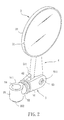
- Fig. 2 is a perspective view of the rearview mirror assembly of Fig. 1;
- Fig. 3 is a perspective view illustrating how the rearview mirror assembly of Fig. 1 is mounted on the handle of a vehicle;
- Fig. 4 is a sectional view to illustrate how a tubular part of a second joint of the rearview mirror assembly of Fig. 1 is mounted on a handle of the vehicle;
- Fig. 5 is an exploded perspective view of the second preferred embodiment of the rearview mirror assembly according to this invention;
- Fig. 6 is a perspective view of the rearview mirror assembly of Fig. 5; and
- Fig. 7 is a perspective view to illustrate how the rearview mirror assembly of Fig. 5 is mounted on the handle of a vehicle.
-
- For the sake of brevity, like elements are denoted by the same reference numerals throughout the disclosure.
- Figs. 1 to 4 illustrate the first preferred embodiment of a rearview mirror assembly according to the present invention for a vehicle 7 (see Fig. 3), such as a motorcycle or a bicycle. The rearview mirror assembly includes: a
mirror 3 with amirror supporting frame 32 and amirror 31 mounted on the mirror-supportingframe 32, the mirror-supportingframe 32 having abottom end 321 that is formed with aspherical recess 322; afirst joint 4 extending in a longitudinal direction and having afirst pivot end 41 and asecond pivot end 42 that is opposite to thefirst pivot end 41 in the longitudinal direction, thefirst pivot end 41 being formed with aspherical insert 411 that conforms to and that is received in therecess 322 so as to permit rotation of the mirror-supportingframe 32 relative to thefirst joint 4; asecond joint 5 extending in the longitudinal direction and having apivot end 51 and afixed end 52 that is opposite to thepivot end 51 of thesecond joint 5 in the longitudinal direction, thepivot end 51 being formed with twoopposing pivot arms 511 that extend in the longitudinal direction and that cooperatively define a receiving space therebetween, thesecond pivot end 42 of thefirst joint 4 being received in the receiving space and being pivoted to thepivot arms 511 of thepivot end 51 of thesecond joint 5 using screw means 53 so as to permit rotation of thefirst joint 4 relative to thesecond joint 5 about a first axis that is transverse to the longitudinal direction, the fixedend 52 being formed with atubular part 55 that has top andbottom ends counter bore 56 therein, thecounter bore 56 extending through the top andbottom ends tubular part 55 in a transverse direction transverse to the longitudinal direction and the first axis, and having an enlargedsection 561 that extends from thetop end 551 of thetubular part 55, and a reducedsection 562 that extends and that is reduced from the enlargedsection 561 to thebottom end 552 of thetubular part 55, thecounter bore 56 being defined by a bore-defining wall that has ashoulder 563 formed between the enlarged and reducedsections bottom end 552 of thetubular part 55 being adapted to be seated on ahandle 71 of thevehicle 7; and a fastening member including ascrew bolt 54 that has ahead 541 and a threadedshank 542 extending and reduced from thehead 541. The threadedshank 542 of thescrew bolt 54 extends through thecounter bore 56, and is adapted to threadedly engage thehandle 71 of thevehicle 7 in such a manner that thehead 541 is received in the enlargedsection 561 of thecounter bore 56 and abuts against theshoulder 563, thereby providing a clamping force to press thetubular part 55 against thehandle 71 of thevehicle 7, which, in turn, provides a resistance to rotation of thesecond joint 5 about a second axis defined by thescrew bolt 54. - Figs. 5 to 7 illustrate the second preferred embodiment of the rearview mirror assembly according to the present invention. The rearview mirror assembly of this embodiment is similar to the previous embodiment shown in Fig. 1, except that the rearview mirror assembly of this embodiment is mounted on the
handle 71 of thevehicle 7 through amounting seat 6. Themounting seat 6 has a flattop end 61, and is formed with a threadedhole 611 that extends inwardly from thetop end 61 of themounting seat 6. Thebottom end 552 of thetubular part 55 is seated on thetop end 61 of themounting seat 6. The threadedshank 542 of thescrew bolt 54 extends through thecounter bore 56 and into the threadedhole 611 in themounting seat 6 and threadedly engages themounting seat 6 so as to secure thesecond joint 5 to themounting seat 6. - The
mounting seat 6 is secured to thehandle 71 of thevehicle 7 using screw means 63, and has aside end face 62 that is transverse to thetop end 61 of themounting seat 6 and that is formed with a plurality ofprotrusions 64 which are adapted to engage retaining grooves (not shown) in thehandle 71 of thevehicle 7. - The structure of the rearview mirror assembly of this invention permits a greater extent of position adjustment of the
mirror 3 in an easy manner as compared to the conventional rearview mirror assemblies.
Claims (3)
- A rearview mirror assembly for a vehicle (7),
characterized by:a mirror-supporting frame (32) having a bottom end (321) that is formed with a spherical recess (322);a first joint (4) extending in a longitudinal direction and having a first pivot end (41) and a second pivot end (42) that is opposite to said first pivot end (41) in said longitudinal direction, said first pivot end (41) being formed with a spherical insert (411) that conforms to and that is received in said recess (322) so as to permit rotation of said mirror-supporting frame (32) relative to said first joint (4);a second joint (5) extending in said longitudinal direction and having a pivot end (51) and a fixed end (52) that is opposite to said pivot end (51) of said second joint (5) in said longitudinal direction, said second pivot end (42) of said first joint (4) being pivoted to said pivot end (51) of said second joint (5) so as to permit rotation of said first joint (4) relative to said second joint (5) about a first axis that is transverse to said longitudinal direction, said fixed end (52) being formed with a tubular part (55) that has top and bottom ends (551, 552) and that defines a counter bore (56) therein, said counter bore (56) extending through said top and bottom ends (551, 552) of said tubular part (55) in a transverse direction transverse to said longitudinal direction and said first axis, and having an enlarged section (561) that extends from said top end (551) of said tubular part (55), and a reduced section (562) that extends and that is reduced from said enlarged section (561) to said bottom end (552) of said tubular part (55), said counter bore (56) being defined by a bore-defining wall that has a shoulder (563) formed between said enlarged and reduced sections (561, 562), said bottom end (552) of said tubular part (55) being adapted to be seated on the vehicle (7) ; anda fastening member including a screw bolt (54) that has a head (541) and a threaded shank (542) extending and reduced from said head (541), said threaded shank (542) of said screw bolt (54) extending through said counter bore (56) and being adapted to threadedly engage the vehicle (7) in such a manner that said head (541) is received in said enlarged section (561) of said counter bore (56) and abuts against said shoulder (563), thereby providing a clamping force to press said tubular part (55) against the vehicle (7) , which, in turn, provides a resistance to rotation of said second joint (5) about a second axis defined by said screw bolt (54). - A rearview mirror assembly adapted to be mounted on a handle (71) of a vehicle (7) , said rearview mirror assembly comprising:wherein said bottom end (552) of said tubular part (55) is seated on said top end (61) of said mounting seat (6); anda mirror-supporting frame (32) having a bottom end (321) that is formed with a spherical recess (322) ;a first joint (4) having a first pivot end (41) and a second pivot end (42) that is opposite to said first pivot end (41), said first pivot end (41) being formed with a spherical insert (411) that conforms to and that is received in said recess (322) so as to permit rotation of said mirror-supporting frame (32) relative to said first joint (4);a second joint (5) extending in a longitudinal direction and having a pivot end (51) and a fixed end (52) that is opposite to said pivot end (51) of said second joint (5), said second pivot end (42) of said first joint (4) being pivoted to said pivot end (51) of said second joint (5) so as to permit rotation of said first joint (4) relative to said second joint (5) about a first axis that is transverse to said longitudinal direction, said fixed end (52) being formed with a tubular part (55) that has top and bottom ends (551, 552) and that defines a counter bore (56) therein, said counter bore (56) extending through said top and bottom ends (551, 552) of said tubular part (55) in a transverse direction transverse to said longitudinal direction and said first axis, and having an enlarged section (561) that extends from said top end (551) of said tubular part (55), and a reduced section (562) that extends and that is reduced from said enlarged section (561) to said bottom end (552) of said tubular part (55), said counter bore (56) being defined by a bore-defining wall that has a shoulder (563) formed between said enlarged and reduced sections (561, 562);a fastening member including a screw bolt (54) that has a head (541) and a threaded shank (542) extending and reduced from said head (541) ; anda mounting seat (6) adapted to be secured to the handle (71) of the vehicle (7), and having a flat top end (61) , said mounting seat (6) being formed with a threaded hole (611) that extends inwardly from said top end (61) of said mounting seat (6);
wherein said threaded shank (542) of said screw bolt (54) extends through said counter bore (56) and into said threaded hole (611) in said mounting seat (6) and threadedly engages said mounting seat (6) in such a manner that said head (541) is received in said enlarged section (561) of said counter bore (56) and abuts against said shoulder (563), thereby providing a clamping force to press said tubular part (55) against said mounting seat (6), which, in turn, provides a resistance to rotation of said second joint (5) about a second axis defined by said screw bolt (54). - The rearview mirror assembly of Claim 2, wherein said mounting seat (6) has a side end face (62) that is transverse to said top end (61) of said mounting seat (6) and that is formed with a plurality of protrusions (64) which are adapted to engage the handle (71) of the vehicle (7).
Priority Applications (1)
| Application Number | Priority Date | Filing Date | Title |
|---|---|---|---|
| EP03252040A EP1464570A1 (en) | 2003-03-31 | 2003-03-31 | Rearview mirror assembly for a vehicle |
Applications Claiming Priority (1)
| Application Number | Priority Date | Filing Date | Title |
|---|---|---|---|
| EP03252040A EP1464570A1 (en) | 2003-03-31 | 2003-03-31 | Rearview mirror assembly for a vehicle |
Publications (1)
| Publication Number | Publication Date |
|---|---|
| EP1464570A1 true EP1464570A1 (en) | 2004-10-06 |
Family
ID=32842844
Family Applications (1)
| Application Number | Title | Priority Date | Filing Date |
|---|---|---|---|
| EP03252040A Withdrawn EP1464570A1 (en) | 2003-03-31 | 2003-03-31 | Rearview mirror assembly for a vehicle |
Country Status (1)
| Country | Link |
|---|---|
| EP (1) | EP1464570A1 (en) |
Cited By (7)
| Publication number | Priority date | Publication date | Assignee | Title |
|---|---|---|---|---|
| US7127965B2 (en) * | 2002-03-21 | 2006-10-31 | Louis Chuang | Grip/mirror combination for bicycle |
| US7780298B2 (en) * | 2007-08-17 | 2010-08-24 | Richard Greathouse | Extenders for motorcycle mirrors |
| US20150101441A1 (en) * | 2013-10-11 | 2015-04-16 | Honda Motor Co., Ltd. | Front structure of saddle-ride type vehicle |
| EP2770868A4 (en) * | 2011-10-27 | 2015-09-30 | Crane Ip Pty Ltd | Wearable reflective device |
| DE102016124286A1 (en) * | 2016-12-14 | 2018-06-14 | Ujet S.A. | Steering unit for a vehicle and vehicle, in particular electric scooter |
| WO2022044133A1 (en) * | 2020-08-25 | 2022-03-03 | glafit株式会社 | Rearview mirror for two-wheeled vehicle |
| KR20230036883A (en) * | 2021-09-08 | 2023-03-15 | 동의대학교 산학협력단 | Bicycle side mirror |
Citations (8)
| Publication number | Priority date | Publication date | Assignee | Title |
|---|---|---|---|---|
| GB822393A (en) * | 1957-06-28 | 1959-10-21 | Alan William Atwell Bruce | Improvements in rear view mirrors for motor cycles and like vehicles |
| GB877760A (en) * | 1957-04-10 | 1961-09-20 | James Neale And Sons Ltd | Means for attaching accessories to handlebars of cycles and like velocipedes |
| GB888178A (en) * | 1957-11-04 | 1962-01-24 | Stadium Ltd | Improvements in attachments for ends of tubular articles |
| US4252290A (en) * | 1978-06-29 | 1981-02-24 | Willey Barry A | Motorcycle safety mirror assemblies |
| WO1982002433A1 (en) * | 1981-01-08 | 1982-07-22 | Barry M Schacht | Ajustable support system for cycle mirror |
| EP0729879A1 (en) * | 1995-02-14 | 1996-09-04 | CATEYE Co., Ltd. | Mounting equipement |
| EP0936135A2 (en) * | 1998-02-13 | 1999-08-18 | Dogaiar S.a.s. di Sante Gaiardoni e C. | Rear view mirror assembly for bicycles |
| DE10235886A1 (en) * | 2001-08-07 | 2003-03-13 | Bernhard Klumpjan | Mirror extension for motorcycles is made of aluminum alloy or hardened aluminum and has a flat profile with specified dimensions |
-
2003
- 2003-03-31 EP EP03252040A patent/EP1464570A1/en not_active Withdrawn
Patent Citations (8)
| Publication number | Priority date | Publication date | Assignee | Title |
|---|---|---|---|---|
| GB877760A (en) * | 1957-04-10 | 1961-09-20 | James Neale And Sons Ltd | Means for attaching accessories to handlebars of cycles and like velocipedes |
| GB822393A (en) * | 1957-06-28 | 1959-10-21 | Alan William Atwell Bruce | Improvements in rear view mirrors for motor cycles and like vehicles |
| GB888178A (en) * | 1957-11-04 | 1962-01-24 | Stadium Ltd | Improvements in attachments for ends of tubular articles |
| US4252290A (en) * | 1978-06-29 | 1981-02-24 | Willey Barry A | Motorcycle safety mirror assemblies |
| WO1982002433A1 (en) * | 1981-01-08 | 1982-07-22 | Barry M Schacht | Ajustable support system for cycle mirror |
| EP0729879A1 (en) * | 1995-02-14 | 1996-09-04 | CATEYE Co., Ltd. | Mounting equipement |
| EP0936135A2 (en) * | 1998-02-13 | 1999-08-18 | Dogaiar S.a.s. di Sante Gaiardoni e C. | Rear view mirror assembly for bicycles |
| DE10235886A1 (en) * | 2001-08-07 | 2003-03-13 | Bernhard Klumpjan | Mirror extension for motorcycles is made of aluminum alloy or hardened aluminum and has a flat profile with specified dimensions |
Cited By (9)
| Publication number | Priority date | Publication date | Assignee | Title |
|---|---|---|---|---|
| US7127965B2 (en) * | 2002-03-21 | 2006-10-31 | Louis Chuang | Grip/mirror combination for bicycle |
| US7780298B2 (en) * | 2007-08-17 | 2010-08-24 | Richard Greathouse | Extenders for motorcycle mirrors |
| EP2770868A4 (en) * | 2011-10-27 | 2015-09-30 | Crane Ip Pty Ltd | Wearable reflective device |
| US20150101441A1 (en) * | 2013-10-11 | 2015-04-16 | Honda Motor Co., Ltd. | Front structure of saddle-ride type vehicle |
| US10246159B2 (en) * | 2013-10-11 | 2019-04-02 | Honda Motor Co., Ltd. | Front structure of saddle-ride type vehicle |
| DE102016124286A1 (en) * | 2016-12-14 | 2018-06-14 | Ujet S.A. | Steering unit for a vehicle and vehicle, in particular electric scooter |
| WO2018108346A1 (en) * | 2016-12-14 | 2018-06-21 | Ujet S.A. | Steering unit for a vehicle and a vehicle, in particular an electric scooter |
| WO2022044133A1 (en) * | 2020-08-25 | 2022-03-03 | glafit株式会社 | Rearview mirror for two-wheeled vehicle |
| KR20230036883A (en) * | 2021-09-08 | 2023-03-15 | 동의대학교 산학협력단 | Bicycle side mirror |
Similar Documents
| Publication | Publication Date | Title |
|---|---|---|
| US5244301A (en) | Bicycle seat mount | |
| US7621595B1 (en) | Bicycle seat having position and angle adjustment functions | |
| US6702376B1 (en) | Tilting angle-adjustable bicycle saddle | |
| US7192044B2 (en) | Bicycle headset | |
| NL1028162C1 (en) | Adjustable bicycle handlebar. | |
| US5515744A (en) | Adjustable stem member | |
| US5921624A (en) | Seat assembly for a bicycle | |
| US5383706A (en) | Adjusting assembly for bicycle seat | |
| US6467372B2 (en) | Bicycle steering device | |
| US8578814B2 (en) | Bicycle stem with an adjustable tilt | |
| EP1464570A1 (en) | Rearview mirror assembly for a vehicle | |
| US20060006707A1 (en) | Seat post assembly for a bicycle | |
| US20070163401A1 (en) | Angle retaining assembly of a hand tool | |
| US5860902A (en) | Paint roller frame with an adjustable handle | |
| US20100188764A1 (en) | Adjustable rear view mirror | |
| CN101821114B (en) | Compasses including a hinge device and locking structure | |
| US4528865A (en) | Handle for a bicycle | |
| US20060097474A1 (en) | Stem for a bicycle | |
| WO1995025034A1 (en) | Adjustable handlebar shaft | |
| US20090001782A1 (en) | Stepless adjustable seat post assembly | |
| US20060226330A1 (en) | Bar support rack | |
| US7290892B2 (en) | Angle adjustable mirror support | |
| US11453454B2 (en) | Bicycle rearview mirror | |
| JP3030503B2 (en) | Bicycle handle stem | |
| US7052148B2 (en) | Door mirror of automobile |
Legal Events
| Date | Code | Title | Description |
|---|---|---|---|
| PUAI | Public reference made under article 153(3) epc to a published international application that has entered the european phase |
Free format text: ORIGINAL CODE: 0009012 |
|
| AK | Designated contracting states |
Kind code of ref document: A1 Designated state(s): AT BE BG CH CY CZ DE DK EE ES FI FR GB GR HU IE IT LI LU MC NL PT RO SE SI SK TR |
|
| AX | Request for extension of the european patent |
Extension state: AL LT LV MK |
|
| 17P | Request for examination filed |
Effective date: 20041207 |
|
| AKX | Designation fees paid |
Designated state(s): AT BE BG CH CY CZ DE DK EE ES FI FR GB GR HU IE IT LI LU MC NL PT RO SE SI SK TR |
|
| 17Q | First examination report despatched |
Effective date: 20070228 |
|
| STAA | Information on the status of an ep patent application or granted ep patent |
Free format text: STATUS: THE APPLICATION IS DEEMED TO BE WITHDRAWN |
|
| 18D | Application deemed to be withdrawn |
Effective date: 20090211 |