EP1449718A2 - Leseleuchte für Flugzeugkabinen - Google Patents
Leseleuchte für Flugzeugkabinen Download PDFInfo
- Publication number
- EP1449718A2 EP1449718A2 EP04000811A EP04000811A EP1449718A2 EP 1449718 A2 EP1449718 A2 EP 1449718A2 EP 04000811 A EP04000811 A EP 04000811A EP 04000811 A EP04000811 A EP 04000811A EP 1449718 A2 EP1449718 A2 EP 1449718A2
- Authority
- EP
- European Patent Office
- Prior art keywords
- reading light
- housing
- mirror
- light according
- reading
- Prior art date
- Legal status (The legal status is an assumption and is not a legal conclusion. Google has not performed a legal analysis and makes no representation as to the accuracy of the status listed.)
- Granted
Links
- 230000003287 optical effect Effects 0.000 claims abstract description 33
- 229910052736 halogen Inorganic materials 0.000 claims abstract description 4
- 150000002367 halogens Chemical class 0.000 claims abstract description 4
- 230000006835 compression Effects 0.000 claims description 6
- 238000007906 compression Methods 0.000 claims description 6
- 238000009434 installation Methods 0.000 claims description 3
- 230000000712 assembly Effects 0.000 claims description 2
- 238000000429 assembly Methods 0.000 claims description 2
- 239000000725 suspension Substances 0.000 claims 1
- 230000000391 smoking effect Effects 0.000 description 3
- 230000010354 integration Effects 0.000 description 1
Images


Classifications
-
- F—MECHANICAL ENGINEERING; LIGHTING; HEATING; WEAPONS; BLASTING
- F21—LIGHTING
- F21V—FUNCTIONAL FEATURES OR DETAILS OF LIGHTING DEVICES OR SYSTEMS THEREOF; STRUCTURAL COMBINATIONS OF LIGHTING DEVICES WITH OTHER ARTICLES, NOT OTHERWISE PROVIDED FOR
- F21V7/00—Reflectors for light sources
- F21V7/0008—Reflectors for light sources providing for indirect lighting
-
- B—PERFORMING OPERATIONS; TRANSPORTING
- B60—VEHICLES IN GENERAL
- B60Q—ARRANGEMENT OF SIGNALLING OR LIGHTING DEVICES, THE MOUNTING OR SUPPORTING THEREOF OR CIRCUITS THEREFOR, FOR VEHICLES IN GENERAL
- B60Q3/00—Arrangement of lighting devices for vehicle interiors; Lighting devices specially adapted for vehicle interiors
- B60Q3/40—Arrangement of lighting devices for vehicle interiors; Lighting devices specially adapted for vehicle interiors specially adapted for specific vehicle types
- B60Q3/41—Arrangement of lighting devices for vehicle interiors; Lighting devices specially adapted for vehicle interiors specially adapted for specific vehicle types for mass transit vehicles, e.g. buses
- B60Q3/44—Spotlighting, e.g. reading lamps
-
- B—PERFORMING OPERATIONS; TRANSPORTING
- B60—VEHICLES IN GENERAL
- B60Q—ARRANGEMENT OF SIGNALLING OR LIGHTING DEVICES, THE MOUNTING OR SUPPORTING THEREOF OR CIRCUITS THEREFOR, FOR VEHICLES IN GENERAL
- B60Q3/00—Arrangement of lighting devices for vehicle interiors; Lighting devices specially adapted for vehicle interiors
- B60Q3/70—Arrangement of lighting devices for vehicle interiors; Lighting devices specially adapted for vehicle interiors characterised by the purpose
- B60Q3/76—Arrangement of lighting devices for vehicle interiors; Lighting devices specially adapted for vehicle interiors characterised by the purpose for spotlighting, e.g. reading lamps
-
- F—MECHANICAL ENGINEERING; LIGHTING; HEATING; WEAPONS; BLASTING
- F21—LIGHTING
- F21V—FUNCTIONAL FEATURES OR DETAILS OF LIGHTING DEVICES OR SYSTEMS THEREOF; STRUCTURAL COMBINATIONS OF LIGHTING DEVICES WITH OTHER ARTICLES, NOT OTHERWISE PROVIDED FOR
- F21V13/00—Producing particular characteristics or distribution of the light emitted by means of a combination of elements specified in two or more of main groups F21V1/00 - F21V11/00
- F21V13/12—Combinations of only three kinds of elements
-
- F—MECHANICAL ENGINEERING; LIGHTING; HEATING; WEAPONS; BLASTING
- F21—LIGHTING
- F21V—FUNCTIONAL FEATURES OR DETAILS OF LIGHTING DEVICES OR SYSTEMS THEREOF; STRUCTURAL COMBINATIONS OF LIGHTING DEVICES WITH OTHER ARTICLES, NOT OTHERWISE PROVIDED FOR
- F21V17/00—Fastening of component parts of lighting devices, e.g. shades, globes, refractors, reflectors, filters, screens, grids or protective cages
- F21V17/02—Fastening of component parts of lighting devices, e.g. shades, globes, refractors, reflectors, filters, screens, grids or protective cages with provision for adjustment
-
- F—MECHANICAL ENGINEERING; LIGHTING; HEATING; WEAPONS; BLASTING
- F21—LIGHTING
- F21V—FUNCTIONAL FEATURES OR DETAILS OF LIGHTING DEVICES OR SYSTEMS THEREOF; STRUCTURAL COMBINATIONS OF LIGHTING DEVICES WITH OTHER ARTICLES, NOT OTHERWISE PROVIDED FOR
- F21V5/00—Refractors for light sources
- F21V5/008—Combination of two or more successive refractors along an optical axis
-
- F—MECHANICAL ENGINEERING; LIGHTING; HEATING; WEAPONS; BLASTING
- F21—LIGHTING
- F21V—FUNCTIONAL FEATURES OR DETAILS OF LIGHTING DEVICES OR SYSTEMS THEREOF; STRUCTURAL COMBINATIONS OF LIGHTING DEVICES WITH OTHER ARTICLES, NOT OTHERWISE PROVIDED FOR
- F21V14/00—Controlling the distribution of the light emitted by adjustment of elements
- F21V14/04—Controlling the distribution of the light emitted by adjustment of elements by movement of reflectors
-
- F—MECHANICAL ENGINEERING; LIGHTING; HEATING; WEAPONS; BLASTING
- F21—LIGHTING
- F21V—FUNCTIONAL FEATURES OR DETAILS OF LIGHTING DEVICES OR SYSTEMS THEREOF; STRUCTURAL COMBINATIONS OF LIGHTING DEVICES WITH OTHER ARTICLES, NOT OTHERWISE PROVIDED FOR
- F21V29/00—Protecting lighting devices from thermal damage; Cooling or heating arrangements specially adapted for lighting devices or systems
- F21V29/50—Cooling arrangements
- F21V29/70—Cooling arrangements characterised by passive heat-dissipating elements, e.g. heat-sinks
- F21V29/74—Cooling arrangements characterised by passive heat-dissipating elements, e.g. heat-sinks with fins or blades
-
- F—MECHANICAL ENGINEERING; LIGHTING; HEATING; WEAPONS; BLASTING
- F21—LIGHTING
- F21V—FUNCTIONAL FEATURES OR DETAILS OF LIGHTING DEVICES OR SYSTEMS THEREOF; STRUCTURAL COMBINATIONS OF LIGHTING DEVICES WITH OTHER ARTICLES, NOT OTHERWISE PROVIDED FOR
- F21V7/00—Reflectors for light sources
- F21V7/04—Optical design
- F21V7/05—Optical design plane
-
- F—MECHANICAL ENGINEERING; LIGHTING; HEATING; WEAPONS; BLASTING
- F21—LIGHTING
- F21Y—INDEXING SCHEME ASSOCIATED WITH SUBCLASSES F21K, F21L, F21S and F21V, RELATING TO THE FORM OR THE KIND OF THE LIGHT SOURCES OR OF THE COLOUR OF THE LIGHT EMITTED
- F21Y2115/00—Light-generating elements of semiconductor light sources
- F21Y2115/10—Light-emitting diodes [LED]
Definitions
- the invention relates to a reading light for aircraft cabins, which installed in particular over a passenger seat and has at least one light source, preferably a small halogen or an LED light.
- the seating (layout) is an adjustment of this Lights in a relatively wide range required.
- the Adjustability requires a lot of installation volume because of the the swiveling axes are not desired in the geometric focus, but very close to the front Limitation, i.e. generally close to one Lens must lie.
- the electrical supply of the lights is often done by means of Ballasts, on the one hand, the electrical energy provide and prepare and on the other hand also one Establish connection to the aircraft's data bus system, to be able to switch and monitor the reading lights.
- Ballasts are also used today to control others Components used in the supply channel, e.g. B. for the Speakers, no smoking and seat belt signs.
- the electrical Connection between the ballasts and the Reading lights take place because of the movable storage of the Reading lights over individual cable bundles.
- the invention is based on the object, a reading lamp of the type mentioned to create the compact is designed with a small installation volume and an adjustment of the lamp in a relatively wide Area allows.
- the achievement of the object is characterized by installing a projecting reading lamp with horizontal lying optical axis, the emitted light rays via an optical deflector in the seating area the associated passenger seat are redirected.
- Embodiments of the invention are in the subclaims 2 described up to 21st
- Advantages of the lamp according to the invention lie in its low level Height and their low volume requirements. Another The advantage is the individual adjustability the lamp by its user. So according to an inventive Training a motorized individual Adjustability of one serving as an optical deflecting means Mirror provided in two axes by means of electric drives. This adjustability can be achieved using, for example arranged in the armrest of a passenger seat Remote control device can be realized, the Actuators receive control signals "right-left” and “up-down” and thus an adjustment of the mirror in two axes enable. Furthermore, an automatic adjustment a reading light depending on a preset Position of the passenger seat take place. Also here through a correlation table that shows a relationship between Seating position of an electrically adjustable seat and the creates optimal reading light position, an automatic The reading light is adjusted.
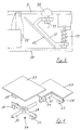
- elongated housing 3 which is preferably a rectangular or cuboid Cross section and thus two opposite end faces 4 and 5 and two longitudinal walls 6 and 7.
- a light source in the area of the end face labeled 4 8 arranged, the optical axis 9 with the housing axis flees.
- Mirror 12 as an optical deflection means 2 in the optical beam path 9 is arranged within the housing 3.
- the mirror 12 directs it from the light source 8 - on the plane horizontal optical axis 9 - emitted light beams in the seating area of an associated passenger seat.
- a lens system 13 which consists of a Focusing lens 14 and a converging lens 15 exist between which is an aperture 16.
- Mirror 12 can also be an angular prism as an optical deflecting means 2 can be provided, each optical used Deflection means 2 for adjusting the beam path 9 can be pivoted is arranged.
- a pivot axis 17 is pivotally attached.
- the opposite end of the Plate 18 is angled, being on the angled face 18a one end of a spring-assisted adjusting screw 19 is attached, the other end in a threaded hole in engages a housing wall 7 and penetrates it.
- a compression spring 20 is arranged between the angled end face 18a and the housing wall 7, arranged.
- the reading lamp 1 shown in FIG. 2 differs from that of Fig. 1 by an enlarged housing part 21 for receiving a mirror 12, which by means of a gimbal 22 on a wall of the enlarged Housing part 21 is attached.
- the gimbal 22 consists of a the plate 12 receiving the mirror 12 with two bearings 24, which cooperate with an axis 25 of a gimbal 26.
- the assembly of plate 23 and gimbal cross 26 can be seen from the right part of FIG. 4.
- the bearings 27 of the other axis 28 of the gimbal 26 are mounted in a fastening element 29, which - as shown in FIG. 2 - the gimbal 26 with a wall of the enlarged housing part 21 mechanically combines.
- the mirror is within this housing part 21 12 with two additional pressure spring-assisted adjustment screws 30 or 31 individually adjustable.
- Fig. 3 shows a section of a reading lamp with a Three-point mounting of the serving as optical deflection means 2 Mirror 12.
- the mirror 12 with a two-dimensional rotary bearing in the form of a Ball head 32 and with two adjustable bearings in the form attached by adjusting screws 33 and 34 within the housing 3.
- Both adjusting screws 33 and 34 are over one Fastening lever 35 to which the mirror 12 is mechanically fastened is connected to each other, adjusting screw 33 with the ball head mounted in a wall of the housing 3 32 is mechanically connected and the adjusting screw 33 pressure spring supported on a wall of the housing 3 is attached.
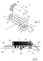
- FIG. 6 shows a reading lamp 1, the is installed in a supply channel of an aircraft, whose front panel is labeled 36.
- the reading lamp 1 with lens 11 mirror drive 37 and heat sink 38 are a speaker 39, one in the supply channel Steward call button and display 40, a no smoking display 41 and other electrical components 42 installed. All Components are on so-called mounting boards 41 mechanically attached that installed in the supply duct are.
- the geometric structure can be advantageous of the entire electrical components of the reading lamp 1 in the form of a block such that if the cabling between reading light 1 and Ballast a complete integration of all electrical and electronic assemblies into one unit.
- this light exit opening 10 can also through a converging lens be covered.
- Can also be used as an optical deflecting means 2 uses a non-adjustable mirror 12 be mounted on a mirror support. With this mirror support can advantageously fixed settings of the optical beam path 9 can be specified.
- a housing 3 has a total of, for example three mirrors 12, which are expediently adjustable are and each of which is not shown in the drawing Light source is assigned.
Abstract
Description
- Fig. 1
- eine projizierende Leseleuchte mit horizontal im Flugzeug liegender optischer Achse,
- Fig. 2
- eine Leseleuchte mit gegenüber der Leseleuchte aus Fig. 1 verändertem Gehäuse und Aufbau,
- Fig. 3
- eine Dreipunktlagerung eines als optisches Umlenkmittel wirkenden Spiegels,
- Fig. 4
- Bauteile einer kardanischen Aufhängung für einen Spiegel,
- Fig. 5
- eine Explosionsdarstellung einer Leseleuchte,
- Fig. 6
- eine in einem Flugzeug-Versorgungskanal angeordnete Leseleuchte, und
- Fig. 7
- ein Gehäuse mit drei Lichtquellen und Spiegeln.
- 1
- projizierende Leseleuchte
- 2
- optisches Umlenkmittel
- 3
- Gehäuse
- 4
- eine Stirnseite des Gehäuses 3
- 5
- andere Stirnseite des Gehäuses 3
- 6
- eine Längswandung des Gehäuses 3
- 7
- andere Längswandung des Gehäuses 3
- 8
- Lichtquelle
- 9
- optische Achse der Lichtquelle 8
- 10
- Lichtaustrittsöffnung
- 11
- Lichtscheibe
- 12
- Spiegel
- 13
- Linsensystem
- 14
- Fokusierlinse des Linsensystems 13
- 15
- Sammellinse des Linsensystems 13
- 16
- Blende des Linsensystems 13
- 17
- Schwenkachse des Spiegels 12
- 18
- Platte für Spiegel 12
- 18a
- angewinkelte Stirnseite der Platte 18
- 19
- Verstellschraube
- 20
- Druckfeder
- 21
- vergrößertes Gehäuseteil
- 22
- kardanische Aufhängung
- 23
- Platte für Spiegel 12
- 24
- Lager für Kardanachsenkreuz 26
- 25
- eine Achse des Kardanachsenkreuzes 26
- 26
- Kardanachsenkreuz
- 27
- Lager für Kardanachsenkreuz 26
- 28
- andere Achse des Kardanachsenkreuzes 26
- 29
- Befestigungselement
- 30
- druckfedergestützte Verstellschrauben
- 31
- druckfedergestützte Verstellschrauben
- 32
- Kugelkopf / dreidimensionales Lager
- 33
- Justierschrauben
- 34
- Justierschrauben
- 35
- Befestigungshebel für Spiegel 12
- 36
- Frontblende des Versorgungskanals
- 37
- Spiegelantrieb
- 38
- Kühlkörper
- 39
- Lautsprecher
- 40
- Stewardruftaste und -anzeige
- 41
- Nichtraucheranzeige
- 42
- elektrische Bauteile
- 43
- Befestigungs-Platinen
Claims (21)
- Leseleuchte für Flugzeugkabinen, die insbesondere über einem Passagiersitz installiert ist und mindestens eine Lichtquelle aufweist, vorzugsweise eine Kleinhalogenoder eine LED-Leuchte, gekennzeichnet durch den Einbau einer projizierenden Leseleuchte (1) mit horizontal liegender optischer Achse, deren ausgesandte Lichtstrahlen über ein optisches Umlenkmittel (2) in den Sitzbereich des zugehörigen Passagiersitzes umgelenkt werden.
- Leseleuchte nach Anspruch 1, dadurch gekennzeichnet, dass ein langgestrecktes Gehäuse (3) mit zwei einander gegenüberliegenden Stirnseiten (4 bzw. 5) vorgesehen ist, dass im Bereich einer der beiden Stirnseiten (4) eine Lichtquelle (8) angeordnet ist, deren optische Achse (9) mit der Gehäuseachse fluchtet, dass im Bereich der anderen Stirnseite (5) eine Lichtaustrittsöffnung (10) in einer Längswandung (6) des Gehäuses (3) vorgesehen ist, und dass im Bereich der Lichtaustrittsöffnung (10) das optische Umlenkmittel (2) innerhalb des Gehäuses (3) angeordnet ist.
- Leseleuchte nach Anspruch 2, gekennzeichnet durch ein langgestrecktes Gehäuse (3) mit rechteckigem oder quaderförmigem Querschnitt.
- Leseleuchte nach Anspruch 2, dadurch gekennzeichnet, dass die Lichtaustrittsöffnung (10) durch eine Lichtscheibe (11) abgedeckt ist.
- Leseleuchte nach Anspruch 1, 2 oder 3, dadurch gekennzeichnet, dass im optischen Strahlengang zwischen Lichtquelle (8) und optischem Umlenkmittel (9) ein Linsensystem (13) innerhalb des Gehäuses (3) angeordnet ist.
- Leseleuchte nach Anspruch 5, dadurch gekennzeichnet, dass das Linsensystem (13) aus einer Fokusierlinse (14) und einer Sammellinse (15) besteht, zwischen denen eine Blende (16) angeordnet ist.
- Leseleuchte nach Anspruch 1, 2 oder 5, dadurch gekennzeichnet, dass als optisches Umlenkmittel (2) ein Spiegel (12) vorgesehen ist.
- Leseleuchte nach Anspruch 1, 2 oder 5, dadurch gekennzeichnet, dass als optisches Umlenkmittel (2) ein Winkelprisma vorgesehen ist.
- Leseleuchte nach Anspruch 1, 2, 5, 6 oder 7, gekennzeichnet durch ein verschwenkbar angeordnetes optisches Umlenkmittel (2) zur Justierung des Strahlenganges.
- Leseleuchte nach Anspruch 1, 2, 5, 7, 8 oder 9, dadurch gekennzeichnet, dass der als optisches Umlenkmittel (2) dienende Spiegel (12) mit einer seiner Stirnseiten an derjenigen Längswandung (7) des Gehäuses (3), die der Lichtaustrittsöffnung (10) gegenüberliegt, um eine Schwenkachse (17) schwenbar befestigt ist.
- Leseleuchte nach Anspruch 9 oder 10, dadurch gekennzeichnet, dass an der Schwenkachse (17) eine Stirnseite einer den Spiegel (12) tragenden Platte (18) befestigt ist, deren gegenüberliegende Stirnseite (18a) angewinkelt ist, dass an dem angewinkelten Stirnseite (18a) ein Ende einer federgestützten Verstellschraube (19) befestigt ist, deren anderes Ende in eine Gewindebohrung in einer Gehäusewandung (7) eingreift und diese durchsetzt, und dass zwischen der angewinkelten Stirnseite (18a) und der Gehäusewandung (7) eine Druckfeder (20) angeordnet ist.
- Leseleuchte nach Anspruch 1, 2, 5, 7, 8 oder 9, dadurch gekennzeichnet, dass der als optisches Umlenkmittel (2) dienende Spiegel (12) durch eine Dreipunktlagerung mit einem zweidimensionalen Drehlager in Form eines Kugelkopfes (32) und mit zwei einstellbaren Lagern in Form von Justierschrauben (33 bzw. 34) innerhalb des Gehäuses (3/21) befestigt ist.
- Leseleuchte nach Anspruch 1, 2, 5, 7, 8 oder 9, dadurch gekennzeichnet, dass der als optisches Umlenkmittel (2) dienende Spiegel (12) durch eine kardanische Aufhängung (22) und Friktionsbremse individuell einstellbar innerhalb des Gehäuses (3/21) gelagert ist.
- Leseleuchte nach Anspruch 13, dadurch gekennzeichnet, dass die kardanische Aufhängung (22) aus einer den Spiegel (12) aufnehmenden Platte (23) mit zwei Lagern (24), einem Kardanachsenkreuz (26) und einem Befestigungselement (29), welches das Kardanachsenkreuz (26) mit einer Wandung des Gehäuses (3) mechanisch verbindet, besteht.
- Leseleuchte nach Anspruch 13 oder 14, dadurch gekennzeichnet, dass der Spiegel (12) durch zwei druckfedergestützte Verstellschrauben (30 bzw. 31) justierbar ist.
- Leseleuchte nach einem der Ansprüche 1, 2, 7 oder 9 bis 15, gekennzeichnet durch eine motorische individuelle Einstellbarkeit des Spiegels (12) mittels elektischer Antriebe in zwei Achsen.
- Leseleuchte nach Anspruch 16, gekennzeichnet durch eine Einstellbarkeit des Spiegels (12) mittels einer in der Armlehne eines Passagiersitzes angeordneten Fernsteuerungseinrichtung.
- Leseleuchte nach Anspruch 16 oder 17, dadurch gekennzeichnet, dass eine automatische Justierung der Leseleuchte (1) in Abhängigkeit von der voreingestellten Position des Passagiersitzes erfolgt.
- Leseleuchte nach einem der Ansprüche 1 bis 18, gekennzeichnet durch einen geometrischen Aufbau der gesamten elektischen Komponenten der Leseleuchte (1) in Form eines derartig ausgebildeten Blockes, dass bei Entfall der Verkabelung zwischen Leseleuchte (1) und Vorschaltgerät eine Komplettintegration aller elektrischer und elektronischer Baugruppen zu einer Einheit erfolgt.
- Leseleuchte nach Anspruch 2, dadurch gekennzeichnet, dass die in der Längswandung (6) des Gehäuses (3) angeordnete Lichtaustrittsöffnung (10) durch eine Sammellinse abgedeckt ist.
- Leseleuchte nach Anspruch 1, 2 oder 5, dadurch gekennzeichnet, dass als optisches Umlenkmittel (2) ein nicht justierbarer Spiegel (12) vorgesehen ist, der auf einem Spiegelträger fest montiert ist und mit dem eine feste Einstellung des optischen Strahlenganges (9) vorgegeben ist.
Applications Claiming Priority (2)
| Application Number | Priority Date | Filing Date | Title |
|---|---|---|---|
| DE10307147 | 2003-02-20 | ||
| DE10307147A DE10307147A1 (de) | 2003-02-20 | 2003-02-20 | Leseleuchte für Flugzeugkabinen |
Publications (3)
| Publication Number | Publication Date |
|---|---|
| EP1449718A2 true EP1449718A2 (de) | 2004-08-25 |
| EP1449718A3 EP1449718A3 (de) | 2007-06-20 |
| EP1449718B1 EP1449718B1 (de) | 2008-07-16 |
Family
ID=32731066
Family Applications (1)
| Application Number | Title | Priority Date | Filing Date |
|---|---|---|---|
| EP04000811A Expired - Lifetime EP1449718B1 (de) | 2003-02-20 | 2004-01-16 | Leseleuchte für Flugzeugkabinen |
Country Status (4)
| Country | Link |
|---|---|
| US (1) | US7150548B2 (de) |
| EP (1) | EP1449718B1 (de) |
| AT (1) | ATE401215T1 (de) |
| DE (2) | DE10307147A1 (de) |
Cited By (1)
| Publication number | Priority date | Publication date | Assignee | Title |
|---|---|---|---|---|
| ITBZ20130057A1 (it) * | 2013-11-19 | 2015-05-20 | Aggiutorio Federico Nardone | Sistema di illuminazione non abbagliante |
Families Citing this family (26)
| Publication number | Priority date | Publication date | Assignee | Title |
|---|---|---|---|---|
| DE102004051826A1 (de) * | 2004-10-25 | 2006-05-04 | Zumtobel Staff Gmbh | Eckleuchte |
| US20070035955A1 (en) * | 2005-01-27 | 2007-02-15 | Airbus Deutschland Gmbh | Light for use for a passenger seat |
| US8116017B2 (en) * | 2006-03-14 | 2012-02-14 | Abet Technologies, Inc. | Reduced vibration optical system with inexpensive precision positioning assembly |
| JP4508172B2 (ja) * | 2006-08-24 | 2010-07-21 | 市光工業株式会社 | 車両用ルームランプ |
| JP4706598B2 (ja) * | 2006-08-24 | 2011-06-22 | 市光工業株式会社 | 車両用ルームランプ |
| CA2695245A1 (en) * | 2007-08-07 | 2009-02-12 | Johnson Controls Technology Company | Lighting system |
| DE102008029511A1 (de) | 2008-06-21 | 2010-02-11 | Airbus Deutschland Gmbh | Lese- oder Spotleuchte |
| DE102008058271A1 (de) * | 2008-11-20 | 2010-05-27 | Airbus Deutschland Gmbh | Versorgungseinheit für flexible Versorgungskanäle |
| US8052311B2 (en) * | 2008-11-26 | 2011-11-08 | Ilo Kristo Xhunga | Pull-down self-supportive lighting mounted on hand-reachable ceilings |
| DE102009018111A1 (de) | 2009-04-20 | 2010-10-28 | Airbus Deutschland Gmbh | Einfach konfigurierbares Multifunktionsmodul für einen Passagierversorgungskanal |
| DE102011013368B4 (de) | 2011-03-08 | 2024-02-01 | Diehl Aerospace Gmbh | Passagier-Serviceeinheit, Passagier-Servicekanal sowie Verkehrsmittel |
| BR112013026617A2 (pt) * | 2011-04-21 | 2016-12-27 | Koninkl Philips Nv | conjunto de iluminação, soquete para receber o conjunto de iluminação e luminária |
| DE102011076777A1 (de) * | 2011-05-31 | 2012-12-06 | Flextronics Automotive Gmbh & Co.Kg | Adaptive Fahrzeugdach-Innenleuchte |
| EP2546102A1 (de) * | 2011-07-11 | 2013-01-16 | Intertechnique | Leselichteinheit und System einer Lichtsteuereinheit und Leselichteinheit |
| US9162617B2 (en) * | 2012-02-14 | 2015-10-20 | C&D Zodiac, Inc. | Pivot bin assembly |
| US9365291B2 (en) | 2012-02-14 | 2016-06-14 | C&D Zodiac, Inc. | Passenger service unit pod assembly |
| DE202013101038U1 (de) * | 2013-02-04 | 2013-06-28 | Truck-Lite Europe Gmbh | Fahrzeuginnenleuchte |
| CN104102083B (zh) * | 2013-04-10 | 2016-01-06 | 扬明光学股份有限公司 | 投影装置 |
| JP5818119B2 (ja) * | 2014-08-29 | 2015-11-18 | トヨタ紡織株式会社 | 車両用照明装置 |
| USD875641S1 (en) | 2015-02-02 | 2020-02-18 | C&D Zodiac, Inc. | Personal service unit |
| USD784904S1 (en) | 2015-02-02 | 2017-04-25 | C&D Zodiac, Inc. | Aircraft passenger service unit |
| US10214287B2 (en) * | 2016-02-26 | 2019-02-26 | The Boeing Company | Vehicle cabin wayfinding assembly |
| JP6650619B2 (ja) * | 2016-03-10 | 2020-02-19 | パナソニックIpマネジメント株式会社 | 照明システム及び移動体 |
| US11167690B2 (en) * | 2016-06-22 | 2021-11-09 | The Boeing Company | Accent lighting system for an interior cabin of a vehicle |
| US10851971B1 (en) * | 2020-02-17 | 2020-12-01 | Signify Holding B.V. | Adjustable light fixtures |
| EP4242060A1 (de) * | 2022-03-08 | 2023-09-13 | Goodrich Lighting Systems GmbH & Co. KG | Flugzeugpassagier-leselicht |
Citations (5)
| Publication number | Priority date | Publication date | Assignee | Title |
|---|---|---|---|---|
| EP0847897A2 (de) * | 1996-12-14 | 1998-06-17 | Hella KG Hueck & Co. | Leseleuchte |
| EP0847896A2 (de) * | 1996-12-14 | 1998-06-17 | Hella KG Hueck & Co. | Leseleuchte |
| DE29919032U1 (de) * | 1999-10-29 | 1999-12-30 | Hella Kg Hueck & Co | Innenleuchte für Kraftfahrzeuge |
| FR2815696A3 (fr) * | 2000-10-24 | 2002-04-26 | Hella Kg Hueck & Co | Dispositif d'eclairage a l'interieur de l'habitacle d'un vehicule |
| WO2003027990A2 (en) * | 2001-09-26 | 2003-04-03 | Grutze Glen A | Gobo projector for a vehicle |
Family Cites Families (7)
| Publication number | Priority date | Publication date | Assignee | Title |
|---|---|---|---|---|
| US963036A (en) * | 1909-10-18 | 1910-07-05 | Henry L De Zeng | Headlight or illuminator. |
| US1201350A (en) * | 1915-12-14 | 1916-10-17 | Rubert S Royce | Electric head-lamp. |
| US2539104A (en) * | 1945-07-26 | 1951-01-23 | Rodel Arthur | Forehead lamps, particularly for medical purposes |
| US2517422A (en) * | 1948-04-24 | 1950-08-01 | Gellman Harold | Forehead lamp device for doctors |
| FR2705435B1 (fr) | 1993-05-14 | 1995-07-21 | Ermax | Agencement de source d'éclairage à fibre optique et à faisceau lumineux orientable. |
| DE19907815A1 (de) * | 1999-02-24 | 2000-08-31 | Hella Kg Hueck & Co | Leseleuchte |
| EP1200775A1 (de) * | 1999-07-01 | 2002-05-02 | Jari Ruuttu | Beleuchtungseinrichtung |
-
2003
- 2003-02-20 DE DE10307147A patent/DE10307147A1/de not_active Ceased
-
2004
- 2004-01-16 EP EP04000811A patent/EP1449718B1/de not_active Expired - Lifetime
- 2004-01-16 AT AT04000811T patent/ATE401215T1/de not_active IP Right Cessation
- 2004-01-16 DE DE502004007584T patent/DE502004007584D1/de not_active Expired - Lifetime
- 2004-02-19 US US10/783,949 patent/US7150548B2/en active Active
Patent Citations (5)
| Publication number | Priority date | Publication date | Assignee | Title |
|---|---|---|---|---|
| EP0847897A2 (de) * | 1996-12-14 | 1998-06-17 | Hella KG Hueck & Co. | Leseleuchte |
| EP0847896A2 (de) * | 1996-12-14 | 1998-06-17 | Hella KG Hueck & Co. | Leseleuchte |
| DE29919032U1 (de) * | 1999-10-29 | 1999-12-30 | Hella Kg Hueck & Co | Innenleuchte für Kraftfahrzeuge |
| FR2815696A3 (fr) * | 2000-10-24 | 2002-04-26 | Hella Kg Hueck & Co | Dispositif d'eclairage a l'interieur de l'habitacle d'un vehicule |
| WO2003027990A2 (en) * | 2001-09-26 | 2003-04-03 | Grutze Glen A | Gobo projector for a vehicle |
Cited By (1)
| Publication number | Priority date | Publication date | Assignee | Title |
|---|---|---|---|---|
| ITBZ20130057A1 (it) * | 2013-11-19 | 2015-05-20 | Aggiutorio Federico Nardone | Sistema di illuminazione non abbagliante |
Also Published As
| Publication number | Publication date |
|---|---|
| US7150548B2 (en) | 2006-12-19 |
| DE502004007584D1 (de) | 2008-08-28 |
| US20040213005A1 (en) | 2004-10-28 |
| EP1449718A3 (de) | 2007-06-20 |
| EP1449718B1 (de) | 2008-07-16 |
| DE10307147A1 (de) | 2004-09-23 |
| ATE401215T1 (de) | 2008-08-15 |
Similar Documents
| Publication | Publication Date | Title |
|---|---|---|
| EP1449718A2 (de) | Leseleuchte für Flugzeugkabinen | |
| EP3819545B1 (de) | Gargerät mit schwenkbare beleuchtungseinrichtung | |
| DE102005045225A1 (de) | Optische Einrichtung und Bildprojektor mit der optischen Einrichtung | |
| EP1568935A1 (de) | Operationsleuchte | |
| DE10065560A1 (de) | Oberflächeninspektionseinheit | |
| DE2740487B2 (de) | Elektronisches Blitzgerät | |
| DD245502B1 (de) | Projektor fuer fixsternprojektion | |
| DE2212502A1 (de) | Anordnung zur hochprojektion und hochprojektor | |
| DE19645023A1 (de) | Lampenvorrichtung eines Flüssigkristall-Projektionsgerätes | |
| DE102020003853B4 (de) | Winkeleinstellmechanismus und fourier-transform-infrarotspektrophotometer, das mit diesem ausgestattet ist | |
| DE102006018297A1 (de) | Modulares Beleuchtungssystem und Beleuchtungsanordnung | |
| DE602004004926T2 (de) | Zur erzeugung eines bildes von fingerabdrücken geeignete optische abbildungseinrichtung | |
| EP3270043B9 (de) | Mehrkomponentenreflektor für lichtmodul eines kraftfahrzeugscheinwerfers | |
| DE10331532A1 (de) | Beleuchtungsvorrichtung | |
| DE102016011561B4 (de) | Leuchte und Leuchtenanordnung für einen Innenraum eines Fahrzeugs | |
| EP0660943B1 (de) | Mikroskopstativfuss | |
| DE202007001258U1 (de) | Stirnlampe | |
| DE10260364A1 (de) | Mikroskop | |
| DE2130969A1 (de) | Optisches Anzeigegeraet mit Abbildung in Unendlichen,insbesondere als Frontscheibenanzeige in einem Flugzeug | |
| DE10126291A1 (de) | Mikroskop | |
| EP0694894A2 (de) | Signalleuchte | |
| EP3088795B1 (de) | Leuchtvorrichtung | |
| DE3525526C1 (en) | Motion-picture film camera with viewing magnifier extension | |
| DE4429519C1 (de) | Konsole für Schiffsbrücke | |
| EP2436557A2 (de) | Verstellvorrichtung zum Verstellen eines optisch relevanten Bauteils eines Fahrzeugscheinwerfers |
Legal Events
| Date | Code | Title | Description |
|---|---|---|---|
| PUAI | Public reference made under article 153(3) epc to a published international application that has entered the european phase |
Free format text: ORIGINAL CODE: 0009012 |
|
| AK | Designated contracting states |
Kind code of ref document: A2 Designated state(s): AT BE BG CH CY CZ DE DK EE ES FI FR GB GR HU IE IT LI LU MC NL PT RO SE SI SK TR |
|
| AX | Request for extension of the european patent |
Extension state: AL LT LV MK |
|
| PUAL | Search report despatched |
Free format text: ORIGINAL CODE: 0009013 |
|
| AK | Designated contracting states |
Kind code of ref document: A3 Designated state(s): AT BE BG CH CY CZ DE DK EE ES FI FR GB GR HU IE IT LI LU MC NL PT RO SE SI SK TR |
|
| AX | Request for extension of the european patent |
Extension state: AL LT LV MK |
|
| 17P | Request for examination filed |
Effective date: 20071220 |
|
| AKX | Designation fees paid |
Designated state(s): AT BE BG CH CY CZ DE DK EE ES FI FR GB GR HU IE IT LI LU MC NL PT RO SE SI SK TR |
|
| GRAP | Despatch of communication of intention to grant a patent |
Free format text: ORIGINAL CODE: EPIDOSNIGR1 |
|
| GRAS | Grant fee paid |
Free format text: ORIGINAL CODE: EPIDOSNIGR3 |
|
| GRAA | (expected) grant |
Free format text: ORIGINAL CODE: 0009210 |
|
| AK | Designated contracting states |
Kind code of ref document: B1 Designated state(s): AT BE BG CH CY CZ DE DK EE ES FI FR GB GR HU IE IT LI LU MC NL PT RO SE SI SK TR |
|
| REG | Reference to a national code |
Ref country code: GB Ref legal event code: FG4D Free format text: NOT ENGLISH |
|
| REG | Reference to a national code |
Ref country code: CH Ref legal event code: EP |
|
| REF | Corresponds to: |
Ref document number: 502004007584 Country of ref document: DE Date of ref document: 20080828 Kind code of ref document: P |
|
| REG | Reference to a national code |
Ref country code: IE Ref legal event code: FG4D Free format text: LANGUAGE OF EP DOCUMENT: GERMAN |
|
| REG | Reference to a national code |
Ref country code: SE Ref legal event code: TRGR |
|
| NLV1 | Nl: lapsed or annulled due to failure to fulfill the requirements of art. 29p and 29m of the patents act | ||
| PG25 | Lapsed in a contracting state [announced via postgrant information from national office to epo] |
Ref country code: PT Free format text: LAPSE BECAUSE OF FAILURE TO SUBMIT A TRANSLATION OF THE DESCRIPTION OR TO PAY THE FEE WITHIN THE PRESCRIBED TIME-LIMIT Effective date: 20081216 Ref country code: ES Free format text: LAPSE BECAUSE OF FAILURE TO SUBMIT A TRANSLATION OF THE DESCRIPTION OR TO PAY THE FEE WITHIN THE PRESCRIBED TIME-LIMIT Effective date: 20081027 Ref country code: NL Free format text: LAPSE BECAUSE OF FAILURE TO SUBMIT A TRANSLATION OF THE DESCRIPTION OR TO PAY THE FEE WITHIN THE PRESCRIBED TIME-LIMIT Effective date: 20080716 |
|
| PG25 | Lapsed in a contracting state [announced via postgrant information from national office to epo] |
Ref country code: BG Free format text: LAPSE BECAUSE OF FAILURE TO SUBMIT A TRANSLATION OF THE DESCRIPTION OR TO PAY THE FEE WITHIN THE PRESCRIBED TIME-LIMIT Effective date: 20081016 Ref country code: FI Free format text: LAPSE BECAUSE OF FAILURE TO SUBMIT A TRANSLATION OF THE DESCRIPTION OR TO PAY THE FEE WITHIN THE PRESCRIBED TIME-LIMIT Effective date: 20080716 Ref country code: SI Free format text: LAPSE BECAUSE OF FAILURE TO SUBMIT A TRANSLATION OF THE DESCRIPTION OR TO PAY THE FEE WITHIN THE PRESCRIBED TIME-LIMIT Effective date: 20080716 |
|
| REG | Reference to a national code |
Ref country code: IE Ref legal event code: FD4D |
|
| PG25 | Lapsed in a contracting state [announced via postgrant information from national office to epo] |
Ref country code: EE Free format text: LAPSE BECAUSE OF FAILURE TO SUBMIT A TRANSLATION OF THE DESCRIPTION OR TO PAY THE FEE WITHIN THE PRESCRIBED TIME-LIMIT Effective date: 20080716 Ref country code: DK Free format text: LAPSE BECAUSE OF FAILURE TO SUBMIT A TRANSLATION OF THE DESCRIPTION OR TO PAY THE FEE WITHIN THE PRESCRIBED TIME-LIMIT Effective date: 20080716 Ref country code: IE Free format text: LAPSE BECAUSE OF FAILURE TO SUBMIT A TRANSLATION OF THE DESCRIPTION OR TO PAY THE FEE WITHIN THE PRESCRIBED TIME-LIMIT Effective date: 20080716 |
|
| PLBE | No opposition filed within time limit |
Free format text: ORIGINAL CODE: 0009261 |
|
| STAA | Information on the status of an ep patent application or granted ep patent |
Free format text: STATUS: NO OPPOSITION FILED WITHIN TIME LIMIT |
|
| PG25 | Lapsed in a contracting state [announced via postgrant information from national office to epo] |
Ref country code: SK Free format text: LAPSE BECAUSE OF FAILURE TO SUBMIT A TRANSLATION OF THE DESCRIPTION OR TO PAY THE FEE WITHIN THE PRESCRIBED TIME-LIMIT Effective date: 20080716 Ref country code: CZ Free format text: LAPSE BECAUSE OF FAILURE TO SUBMIT A TRANSLATION OF THE DESCRIPTION OR TO PAY THE FEE WITHIN THE PRESCRIBED TIME-LIMIT Effective date: 20080716 Ref country code: RO Free format text: LAPSE BECAUSE OF FAILURE TO SUBMIT A TRANSLATION OF THE DESCRIPTION OR TO PAY THE FEE WITHIN THE PRESCRIBED TIME-LIMIT Effective date: 20080716 |
|
| 26N | No opposition filed |
Effective date: 20090417 |
|
| PG25 | Lapsed in a contracting state [announced via postgrant information from national office to epo] |
Ref country code: MC Free format text: LAPSE BECAUSE OF NON-PAYMENT OF DUE FEES Effective date: 20090131 |
|
| REG | Reference to a national code |
Ref country code: CH Ref legal event code: PL |
|
| PG25 | Lapsed in a contracting state [announced via postgrant information from national office to epo] |
Ref country code: CH Free format text: LAPSE BECAUSE OF NON-PAYMENT OF DUE FEES Effective date: 20090131 Ref country code: LI Free format text: LAPSE BECAUSE OF NON-PAYMENT OF DUE FEES Effective date: 20090131 |
|
| PG25 | Lapsed in a contracting state [announced via postgrant information from national office to epo] |
Ref country code: BE Free format text: LAPSE BECAUSE OF NON-PAYMENT OF DUE FEES Effective date: 20090131 |
|
| PG25 | Lapsed in a contracting state [announced via postgrant information from national office to epo] |
Ref country code: AT Free format text: LAPSE BECAUSE OF NON-PAYMENT OF DUE FEES Effective date: 20090116 |
|
| PG25 | Lapsed in a contracting state [announced via postgrant information from national office to epo] |
Ref country code: GR Free format text: LAPSE BECAUSE OF FAILURE TO SUBMIT A TRANSLATION OF THE DESCRIPTION OR TO PAY THE FEE WITHIN THE PRESCRIBED TIME-LIMIT Effective date: 20081017 |
|
| PG25 | Lapsed in a contracting state [announced via postgrant information from national office to epo] |
Ref country code: LU Free format text: LAPSE BECAUSE OF NON-PAYMENT OF DUE FEES Effective date: 20090116 |
|
| PG25 | Lapsed in a contracting state [announced via postgrant information from national office to epo] |
Ref country code: HU Free format text: LAPSE BECAUSE OF FAILURE TO SUBMIT A TRANSLATION OF THE DESCRIPTION OR TO PAY THE FEE WITHIN THE PRESCRIBED TIME-LIMIT Effective date: 20090117 |
|
| PG25 | Lapsed in a contracting state [announced via postgrant information from national office to epo] |
Ref country code: TR Free format text: LAPSE BECAUSE OF FAILURE TO SUBMIT A TRANSLATION OF THE DESCRIPTION OR TO PAY THE FEE WITHIN THE PRESCRIBED TIME-LIMIT Effective date: 20080716 |
|
| PG25 | Lapsed in a contracting state [announced via postgrant information from national office to epo] |
Ref country code: CY Free format text: LAPSE BECAUSE OF FAILURE TO SUBMIT A TRANSLATION OF THE DESCRIPTION OR TO PAY THE FEE WITHIN THE PRESCRIBED TIME-LIMIT Effective date: 20080716 |
|
| REG | Reference to a national code |
Ref country code: FR Ref legal event code: CD Owner name: AIRBUS OPERATIONS GMBH Effective date: 20111118 |
|
| REG | Reference to a national code |
Ref country code: FR Ref legal event code: PLFP Year of fee payment: 13 |
|
| PGFP | Annual fee paid to national office [announced via postgrant information from national office to epo] |
Ref country code: IT Payment date: 20160127 Year of fee payment: 13 |
|
| PGFP | Annual fee paid to national office [announced via postgrant information from national office to epo] |
Ref country code: SE Payment date: 20160120 Year of fee payment: 13 |
|
| REG | Reference to a national code |
Ref country code: DE Ref legal event code: R079 Ref document number: 502004007584 Country of ref document: DE Free format text: PREVIOUS MAIN CLASS: B60Q0003020000 Ipc: B60Q0003200000 |
|
| REG | Reference to a national code |
Ref country code: FR Ref legal event code: PLFP Year of fee payment: 14 |
|
| PG25 | Lapsed in a contracting state [announced via postgrant information from national office to epo] |
Ref country code: SE Free format text: LAPSE BECAUSE OF NON-PAYMENT OF DUE FEES Effective date: 20170117 |
|
| REG | Reference to a national code |
Ref country code: FR Ref legal event code: PLFP Year of fee payment: 15 |
|
| PG25 | Lapsed in a contracting state [announced via postgrant information from national office to epo] |
Ref country code: IT Free format text: LAPSE BECAUSE OF NON-PAYMENT OF DUE FEES Effective date: 20170116 |
|
| PGFP | Annual fee paid to national office [announced via postgrant information from national office to epo] |
Ref country code: GB Payment date: 20220119 Year of fee payment: 19 Ref country code: DE Payment date: 20220119 Year of fee payment: 19 |
|
| PGFP | Annual fee paid to national office [announced via postgrant information from national office to epo] |
Ref country code: FR Payment date: 20220119 Year of fee payment: 19 |
|
| REG | Reference to a national code |
Ref country code: DE Ref legal event code: R119 Ref document number: 502004007584 Country of ref document: DE |
|
| GBPC | Gb: european patent ceased through non-payment of renewal fee |
Effective date: 20230116 |
|
| PG25 | Lapsed in a contracting state [announced via postgrant information from national office to epo] |
Ref country code: GB Free format text: LAPSE BECAUSE OF NON-PAYMENT OF DUE FEES Effective date: 20230116 Ref country code: DE Free format text: LAPSE BECAUSE OF NON-PAYMENT OF DUE FEES Effective date: 20230801 |
|
| PG25 | Lapsed in a contracting state [announced via postgrant information from national office to epo] |
Ref country code: FR Free format text: LAPSE BECAUSE OF NON-PAYMENT OF DUE FEES Effective date: 20230131 |