FIELD OF THE INVENTION AND RELATED ART
-
This invention relates to a linear
motor suitably usable as a drive source for a
stage system being incorporated into an exposure
apparatus, for example, for producing
semiconductor devices, for example. In other
aspects, the invention concerns a stage system, an
exposure apparatus, and a device manufacturing
method, all using such linear motor.
-
Japanese Laid-Open Patent Application
No. 2002-325421, for example, shows a linear motor
in which magnets and coils are relatively moved
relative to each other, by means of a Lorentz's
force produced therebetween.
-
This linear motor comprises (i) a first
magnet group having a plurality of first magnets
disposed so that their polar directions are
periodically opposed to each other and a plurality
of second magnets disposed, in juxtaposition with
the first magnets, so that their polar directions
are periodically opposed to each other, and (ii) a
second magnet group having a plurality of third
magnets disposed so that their polar directions
are periodically opposed to each other and a
plurality of fourth magnets disposed, in
juxtaposition with the first magnets, so that
their polar directions are periodically opposed to
each other, these components being connected
integrally at the top and bottom surfaces of a
holding member, respectively, to provide a movable
element.
-
Also, there is a plurality of
electromagnetic coils disposed opposed to the
first and second magnet groups, to provide a
stator. By applying an electric current to these
coils, a Lorentz's force as a thrust for driving
the movable element is produced between the stator
and the movable element.
SUMMARY OF THE INVENTION
-
Generally, in linear motors, by
providing a coil and a magnet (permanent magnet)
opposed to each other, a Lorentz's force as a
thrust force is produced in the movement direction
of a movable element. The inventor of the subject
application has found that, between a movable
element and a stator of a linear motor, there is a
force additionally produced in a direction other
5 than the thrust producing direction (movement
direction of the movable element), and that such
force is seriously influential to the movable
element. Specifically, such unwanted force being
separate from the thrust force in the movement
direction of the movable element, may function to
move the movable element relatively to the stator
in a direction intersecting with the thrust
producing direction, particularly, in a direction
perpendicular to the thrust producing direction,
thereby to cause a phenomenon that the movable
element approaches toward the stator or contacts
it. Additionally, such unwanted force may
function to cause a phenomenon that the movable
element tilts relative to the stator.
-
Such phenomenon as described above
makes it difficult to assure high-precision
control of the linear motor, and it results in a
degraded positioning precision of a stage system
that uses a linear motor.
-
It is accordingly an object of the
present invention to provide a linear motor that
enables high-precision control. Also, it is an
object of the present invention to improve the
positioning precision of a stage system that uses
a linear motor.
-
The unwanted force different from the
thrust force in the movement direction of the
movable element may result from a phenomenon that
the direction of magnetization or polarization of
the magnet (direction of the magnetic flux vector
from N-pole to S-pole) tilts with respect to the
coil central axis and, consequently, the magnetic
density distribution with respect to the coil
becomes uneven between the upper and lower
portions.
-
Here, as regards the coil central axis,
in the case of a linear motor wherein, as in the
aforementioned Japanese Laid-Open Patent
Application No. 2002-325421, a plurality of coils
are arrayed so that their end faces are placed in
parallel to or substantially in parallel to the
thrust producing direction (movement direction of
the movable element), , it refers to a virtual line
that contains a line passing through or
substantially passing through the center of the
coil and being perpendicular to or substantially
perpendicular to the end face of the coil. The
polar direction of the coil at the coil center is
parallel or substantially parallel to the coil
central axis.
-
Thus, in the case of a linear motor
wherein a plurality of coils are accumulated so
that their end faces are placed perpendicularly to
or substantially perpendicularly to the thrust
producing direction (movement direction of the
movable element), the coil central axis should
refer to a virtual line that contains a line
passing through or substantially passing through
the center of the coil and intersecting or
orthogonally intersecting a line which is
perpendicular to or substantially perpendicular to
the coil end face.
-
In accordance with the present
invention, to achieve the above-described objects,
there is provided a linear motor having a magnet
and a coil, wherein a plurality of magnets are
provided along the central axis direction of the
coil, and the magnetization directions of the
respective magnets have different tilts with
respect to the central axis.
-
In accordance with the present
invention, even if the magnetization direction of
the magnet has a tilt with respect to the coil
central axis, a force to be produced between a
movable element and a stator in a direction other
than the thrust producing direction can be reduced
or avoided. Avoiding such force may include a
case where exactly no force is produced between
the movable element and the stator in a direction
other than the thrust producing direction, and a
case wherein, although a force is produced, it
does not have an adverse influence upon high
precision control of the linear motor.
-
These and other objects, features and
advantages of the present invention will become
more apparent upon a consideration of the
following description of the preferred embodiments
of the present invention taken in conjunction with
the accompanying drawings.
BRIEF DESCRIPTION OF THE DRAWINGS
-
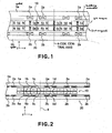
- Figure 1 is a schematic view for
explaining a linear motor according to a first
embodiment of the present invention.
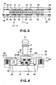
- Figure 2 is a schematic view of a main
portion of the first embodiment of the present
invention.
- Figure 3 is a schematic view of a main
portion of a second embodiment of the present
invention.
- Figure 4 is a schematic view of an
example of exposure apparatus into which a linear
motor according to the present invention can be
incorporated.
- Figure 5 is a flow chart for explaining
device manufacturing processes.
-
DESCRIPTION OF THE PREFERRED EMBODIMENTS
-
Preferred embodiments of the present
invention will now be described with reference to
the attached drawings.
-
Figure 1 shows an embodiment of a
linear motor which is arranged so that, with
respect to an X-Y-Z coordinate system shown in the
drawing, a movable element 10 is moved relatively
to a stator 20 in an X-axis direction.
-
The linear motor comprises first magnet
groups (1a - 1d) including first magnets 1a and 1c
being arrayed with their polar directions placed
periodically in opposite directions or placed in
different directions, and second magnets 1b and 1d
(permanent magnets) being arrayed with their polar
directions placed periodically in opposite
directions or placed in different directions and
being alternately juxtaposed between the first
magnets 1a and 1c. The magnets 1a - 1d of the
first magnet groups are disposed along the X-axis
direction upon one surface of a holding member 7,
made of a magnetic or non-magnetic material, and
they are integrally connected to each other. The
design magnetization direction (direction of
magnetic flux vector from N-pole to S-pole) of the
first magnets 1a and 1c is placed in parallel to
the Y-axis direction which is perpendicular to the
X-axis direction (movement direction of the
movable element 10). The design magnetization
direction of the second magnets 1b and 1d is
parallel to the X-axis direction.
-
Disposed on the other surface of the
holding member 7 are second magnet groups (5a -
5d) arrayed similarly along the X-axis direction.
Like the first magnet groups, the second magnet
groups include third magnets 5a and 5c being
arrayed with their polar directions placed
periodically in opposite directions or placed in
different directions, and fourth magnets 5b and 5d
(permanent magnets) being arrayed with their polar
directions placed periodically in opposite
directions or placed in different directions and
being alternately juxtaposed between the third
magnets 5a and 5c. The design magnetization
direction (direction of magnetic flux vector from
N-pole to S-pole) of the third magnets 5a and 5c
is placed in parallel to the Y-axis direction
which is perpendicular to the X-axis direction
(movement direction of the movable element 10).
The design magnetization direction of the fourth
magnets 5b and 5d is parallel to the X-axis
direction.
-
As far as design is concerned, the
first magnets 1a and 1c and the third magnets 5a
and 5c are placed so that their polar directions
(magnetic flux vector from N-pole to S-pole) are
oriented in the same direction. Also, as far as
design is concerned, the second magnets 1b and 1d
and the fourth magnets 5b and 5d are placed so
that their polar directions are oriented in
opposite directions.
-
The movable element 10 of the linear
motor comprises first magnet groups 1a - 1d,
second magnet groups 5a - 5d and a holding member.
On the other hand, a stator 20 of the linear motor
20 comprises electromagnetic coils 2a and 2b (coil
means), and yokes 3a and 3b for fixedly holding
the electromagnetic coils 2a and 2b, respectively.
The electromagnetic coils 2a and 2b include a coil
wound along an X-Z plane. A coil central axis 8
is a virtual line that contains a line passing
through or substantially passing through the
center of the coils 2a and 2b and being
perpendicular or substantially perpendicular to
the end face of the coil (which is parallel to or
substantially parallel to the X-Z plane). The
polar direction of the coil at the center of the
coils 2a and 2b is parallel to or substantially
parallel to the coil central axis.
-
There is a plurality of upper
electromagnetic coils 2a disposed opposed to the
first magnet groups 1a - 1d, and there is a
plurality of lower electromagnetic coils 2b
disposed opposed to the second magnet groups 5a -
5d. The yoke 3a is provided at one side of the
electromagnetic coil 2a remote from the magnets.
The yoke 3b is provided at one side of the
electromagnetic coil 2b remote from the magnets.
The plurality of electromagnetic coils 2a fixed to
the yoke 3a are disposed with mutual deviations of
90 deg., 180 deg., 270 deg. and 360 deg. in terms
of electrical angle. The plurality of
electromagnetic coils 2b fixed to the yoke 3b are
disposed with mutual deviations of 90 deg., 180
deg., 270 deg. and 360 deg. in terms of electrical
angle.
-
By applying an electric current to the
electromagnetic coils 2a and 2b at the stator 20
side, a Lorentz's force (thrust force) is produced
between the coil and the magnetic groups 1a - 1d
and 5a - 5d at the movable element 10 side, in the
X-axis direction (movement direction of the
movable element).
-
It is to be noted here that in this
embodiment the magnets 1a - 1d and 5a - 5d may be
provided at the linear motor stator side, while
the electromagnetic coils 2a and 2b may be
provided upon the movable element. Further, in
place of providing coils 2a and 2b at the opposite
sides of the magnets 1a - 1d and 5a - 5d, the
magnets 1a - 1d and the magnets 5a - 5d may be
disposed separately with respect to the Y-axis
direction, and coils 2a (or 2b) may be disposed
between them. The present invention is applicable
also to such linear motor structure.
-
Even in this embodiment, the
magnetization direction of the first magnets 1a
and 1c and the third magnets 5a and 5c, in other
words, the vector direction extending from N-pole
to S-pole, is designed to be parallel to the Y-axis
direction (i.e. coil central axis 8).
However, the inventor of the subject application
has found that, actually, the structure may not
exactly follow the design and that the
magnetization direction may tilt in an arbitrary
direction with respect to the Y-axis direction.
-
If this occurs, a difference in
magnetic flux density distribution is produced
between the region where the upper electromagnetic
coil 2a is present and the region where the lower
electromagnetic coil is present, and it results in
production of a thrust force in the Y direction,
in addition to the thrust in the X-axis direction,
as well as production of a rotational force around
the Z axis.
-
This embodiment has a structure as
shown in Figure 2 that is effective to suppress,
reduce or avoid the production of such unwanted
force, other than the thrust to the movable
element 10. In Figure 2, the magnetization
direction of the magnet 1c has a certain
counterclockwise tilt along the X-Y plane, with
respect to the design magnetization direction
which is parallel to or substantially parallel to
the coil central axis 8 (Y-axis direction). Also,
the magnetization direction of the magnet 5c has a
certain clockwise tilt along the X-Y plane, with
respect to the design magnetization direction
which is parallel to or substantially parallel to
the coil central axis 8 (Y-axis direction). Thus,
the magnetization directions of the magnets 1c and
5c have different tilts with respect to the coil
central axis 8, or alternatively, they are tilted
differently.
-
With this arrangement, the magnetic
flux density distribution in the region where the
electromagnetic coil 2a is present and the
magnetic flux density distribution in the region
where the electromagnetic coil 2b is present can
be adjusted to be registered or substantially
registered with each other. By means of this
adjustment, even if a thrust force in the Y
direction other than in the X-axis direction or a
rotational force about the Z-axis is produced at
one of the electromagnetic coil 2a side and the
electromagnetic coil 2b side, the magnetization
direction of the magnet at the other side can be
tilted to completely cancel or substantially
cancel it. Here, substantial cancellation means
reducing the thrust in Y direction or rotational
force about the Z-axis to a level that has
substantially no influence upon the movement of
the movable element 10 in the X-axis direction.
-
Here, it should be noted that this
embodiment may preferably be structured so that
the total sum of tilts of the magnetization
directions of the magnets 1c and 5c with respect
to the coil central axis 8 becomes approximately
null. Furthermore, where in the X-Y plane the
tilt of the magnetization direction of the magnet
1c with respect to the coil central axis 8 is
denoted by Δ1 and the tilt of the magnetization
direction of the magnet 5c with respect to the
coil central axis 8 is denoted by (-Δ5),
preferably the sum of the tilt Δ1 and the tilt
- Δ5 is made equal to or approximately equal to
zero.
-
The adjustment of the magnetization
direction of the magnets 1c and 5c with respect to
the coil central axis 8 is performed by using an
adjusting mechanism (not shown) provided at the
holding member 7 or, alternatively, an adjusting
member sandwiched between the magnets 1c and 5c,
to thereby rotate or tilt at least one of the
magnets 1c and 5c about at least one of the X, Y
and Z axes. The magnets 1a and 5a may preferably
be adjusted into a similar relationship.
-
Figure 3 shows a second embodiment.
This embodiment differs from the first embodiment
in that the adjustment of magnetization direction
is performed also with regard to a set of the
magnets 1b and 5b and a set of the magnets 1d and
5d. Duplicate description of similar structure
and function as of the first embodiment will now
be omitted.
-
This embodiment has a structure as
shown in Figure 3 that is effective to suppress,
reduce or avoid the production of unwanted force,
other than the thrust to the movable element 10.
In Figure 3, the magnetization direction of the
magnet 1b has a certain clockwise tilt along the
X-Y plane, with respect to the design
magnetization direction which is parallel or
substantially parallel to a direction (X-axis
direction) orthogonal to the coil central axis 8
(Y-axis direction). Also, the magnetization
direction of the magnet 5d has a certain
counterclockwise tilt along the X-Y plane, with
respect to the design magnetization direction
which is parallel or substantially parallel to a
direction (X-axis direction) orthogonal to the
coil central axis 8 (Y-axis direction). Thus, the
magnetization directions of the magnets 1b and 5b
have different tilts with respect to the coil
central axis 8, or alternatively, they are tilted
differently.
-
In other words, the magnetization
directions of the magnets 1b and 5b differ from
each other, with certain tilts in opposite
directions, along the X-Y plane, from a direction
parallel to or substantially parallel to the coil
central axis 8 (Y-axis direction).
-
With this arrangement, the magnetic
flux density distribution in the region where the
electromagnetic coil 2a is present and the
magnetic flux density distribution in the region
where the electromagnetic coil 2b is present can
be adjusted to be registered or substantially
registered with each other. By means of this
adjustment, even if a thrust force in the Y
direction other than in the X-axis direction or a
rotational force about the Z-axis is produced at
one of the electromagnetic coil 2a side and the
electromagnetic coil 2b side, the magnetization
direction of the magnet at the other side can be
tilted to completely cancel or substantially
cancel it. Here, substantial cancellation means
reducing the thrust in Y direction or rotational
force about the Z-axis to a level that has
substantially no influence upon the movement of
the movable element 10 in the X-axis direction.
-
Here, it should be noted that this
embodiment may preferably be structured so that
the total sum of tilts of the magnetization
directions of the magnets 1b and 5b with respect
to the coil central axis 8 becomes approximately
null. Furthermore, where in the X-Y plane the
tilt of the magnetization direction of the magnet
1b with respect to the coil central axis 8 is
denoted by Δ1 and the tilt of the magnetization
direction of the magnet 5b with respect to the
coil central axis 8 is denoted by (-Δ5),
preferably the sum of the tilt Δ1 and the tilt
- Δ5 is made equal to or approximately equal to
zero.
-
The adjustment of the magnetization
direction of the magnets 1b and 5b with respect to
the coil central axis 8 is performed by using an
adjusting mechanism (not shown) provided at the
holding member 7 or, alternatively, an adjusting
member sandwiched between the magnets 1b and 5b,
to thereby rotate or tilt at least one of the
magnets 1b and 5b about at least one of the X, Y
and Z axes. The magnets 1d and 5d may preferably
be adjusted into a similar relationship.
-
In the embodiments described above, two
magnets are disposed along the coil central axis
and they are placed with their magnetization
directions tilted differently. However, three or
more magnets may be disposed along the coil
central axis to perform the adjustment for
reducing the thrust in the Y direction or
rotational force about the Z axis.
-
Figure 4 shows a semiconductor device
manufacturing exposure apparatus having a stage
system, as a wafer stage, in which linear motors
M1 and M2 such as described above are incorporated
as a driving means.
-
This exposure apparatus can be used for
manufacture of microdevices, such as semiconductor
devices (e.g. semiconductor integrated circuits),
micromachines, thin-film magnetic heads, for
example, having a fine pattern formed thereon. In
this exposure apparatus, a reticle R (original) is
projected upon a semiconductor wafer W (substrate)
by projecting exposure light (generic term for
visible light, ultraviolet light, EUV light, X-rays,
electron beam, and charged particle beam,
for example) from a light source 61, through a
projection lens (generic term for dioptric lens,
catoptric lens, catadioptric lens system, and
charged particle lens, for example) 62 which is a
projection optical system, whereby a desired
pattern is produced on the substrate.
-
This exposure apparatus has a guide 52
and a linear motor stator 21 fixedly mounted on a
base table 51. Like the example described
hereinbefore, the linear motor stator 21 has
multiple-phase electromagnetic coils while a
linear motor movable element 11 has permanent
magnet groups. The linear motor movable element
11 (moving portion 53) is connected to a movable
guide 54 (stage). Through the drive of the linear
motor M1, the movable guide 54 is moved in a
direction normal to the sheet of the drawing. The
movable portion 53 is supported by static bearing
means 55 with reference to the top face of the
base table 51, and it is supported by static
bearing means 56 with reference to the side face
of the guide 52.
-
A moving stage 57 which is a stage that
straddles the movable guide 54 is supported by
static bearing means 58. This moving stage 57 is
driven by the linear motor M2 like the motor
described above. Thus, the moving stage 57 is
moved horizontally as seen in the sheet of the
drawing, with reference to the movable guide 54.
The motion of the moving stage 57 is measured by
using a mirror 59 fixedly mounted on the moving
stage 57 and an interferometer 60.
-
A wafer W (substrate) is held by a
chuck that is mounted on the moving stage 57, such
that a pattern of the reticle R (original) is
transferred in a reduced scale onto different
regions of the wafer W in a step-and-repeat or
step-and-scan method, by means of a light source
61 and a projection optical system 62.
-
Here, it should be noted that the
linear motor of the present invention is similarly
applicable also to an exposure apparatus of the
type that a circuit pattern is directly drawn on a
semiconductor wafer without using a mask, to
thereby expose a resist thereon.
-
Next, an embodiment of device
manufacturing method that uses an exposure
apparatus such as described above, will be
explained.
-
Figure 5 is a flow chart for explaining
general procedure for production of semiconductor
devices. Step 1 is a design process for designing
a circuit of a semiconductor device. Step 2 is a
process for making a mask on the basis of the
circuit pattern design. Step 3 is a process for
preparing a wafer by using a material such as
silicon. Step 4 is a wafer process which is
called a pre-process wherein, by using the thus
prepared mask and wafer, a circuit is formed on
the wafer in practice, in accordance with
lithography. Step 5 subsequent to this is an
assembling step which is called a post-process
wherein the wafer having been processed at step 4
is formed into semiconductor chips. This step
includes an assembling (dicing and bonding)
process and a packaging (chip sealing) process.
Step 6 is an inspection step wherein an operation
check, a durability check an so on, for the
semiconductor devices produced by step 5, are
carried out. With these processes, semiconductor
devices are produced, and they are shipped (step
7).
-
The wafer process described above
includes an oxidation process for oxidizing the
surface of a wafer; a CVD process for forming an
insulating film on the wafer surface; an electrode
forming process for forming electrodes upon the
wafer by vapor deposition; an ion implanting
process for implanting ions to the wafer; a resist
process for applying a resist (photosensitive
material) to the wafer; and an exposure process
for printing, by exposure, the circuit pattern of
the mask on the wafer through the exposure
apparatus described above. Also, it includes a
developing process for developing the exposed
wafer; an etching process for removing portions
other than the developed resist image; and a
resist separation process for separating the
resist material remaining on the wafer after being
subjected to the etching process. By repeating
these processes, circuit patterns are superposedly
formed on the wafer.
-
While the invention has been described
with reference to the structures disclosed herein,
it is not confined to the details set forth and
this application is intended to cover such
modifications or changes as may come within the
scope of the following claims.