EP1447656A1 - Specimens for transmission electron microscope - Google Patents
Specimens for transmission electron microscope Download PDFInfo
- Publication number
- EP1447656A1 EP1447656A1 EP20030029595 EP03029595A EP1447656A1 EP 1447656 A1 EP1447656 A1 EP 1447656A1 EP 20030029595 EP20030029595 EP 20030029595 EP 03029595 A EP03029595 A EP 03029595A EP 1447656 A1 EP1447656 A1 EP 1447656A1
- Authority
- EP
- European Patent Office
- Prior art keywords
- sample
- fib
- ion beam
- tem
- thickness
- Prior art date
- Legal status (The legal status is an assumption and is not a legal conclusion. Google has not performed a legal analysis and makes no representation as to the accuracy of the status listed.)
- Withdrawn
Links
Images
Classifications
-
- H—ELECTRICITY
- H01—ELECTRIC ELEMENTS
- H01J—ELECTRIC DISCHARGE TUBES OR DISCHARGE LAMPS
- H01J37/00—Discharge tubes with provision for introducing objects or material to be exposed to the discharge, e.g. for the purpose of examination or processing thereof
- H01J37/30—Electron-beam or ion-beam tubes for localised treatment of objects
- H01J37/305—Electron-beam or ion-beam tubes for localised treatment of objects for casting, melting, evaporating or etching
- H01J37/3053—Electron-beam or ion-beam tubes for localised treatment of objects for casting, melting, evaporating or etching for evaporating or etching
- H01J37/3056—Electron-beam or ion-beam tubes for localised treatment of objects for casting, melting, evaporating or etching for evaporating or etching for microworking, e.g. etching of gratings, trimming of electrical components
-
- G—PHYSICS
- G01—MEASURING; TESTING
- G01N—INVESTIGATING OR ANALYSING MATERIALS BY DETERMINING THEIR CHEMICAL OR PHYSICAL PROPERTIES
- G01N1/00—Sampling; Preparing specimens for investigation
- G01N1/28—Preparing specimens for investigation including physical details of (bio-)chemical methods covered elsewhere, e.g. G01N33/50, C12Q
- G01N1/32—Polishing; Etching
-
- H—ELECTRICITY
- H01—ELECTRIC ELEMENTS
- H01J—ELECTRIC DISCHARGE TUBES OR DISCHARGE LAMPS
- H01J2237/00—Discharge tubes exposing object to beam, e.g. for analysis treatment, etching, imaging
- H01J2237/30—Electron or ion beam tubes for processing objects
- H01J2237/317—Processing objects on a microscale
- H01J2237/3174—Etching microareas
- H01J2237/31745—Etching microareas for preparing specimen to be viewed in microscopes or analyzed in microanalysers
Definitions
- the invention relates to a TEM-FIB sample according to The preamble of claim 1 and a method for Production of such a sample according to the preamble of claim 7th
- Samples for transmission electron microscopy can be prepared in different ways. In order to be able to view samples with a TEM, they have to be thinned accordingly so that they can be irradiated in the TEM.
- the quality of the image resolution is very much dependent on the quality of the sample.
- the sample should be set uniformly to a correspondingly desired, defined thickness by means of an appropriate etching process. It is important that the sample structure is not changed by the process itself during this etching process. However, this does not lead to the desired quality of the sample according to today's requirements. In this regard, the wet chemical etching method is not leading.
- the samples are processed with a fixed argon ion beam, which has a diameter of approximately 1 mm, by etching.
- a focused ion beam FIB technique
- a screened, finely focused gallium ion beam with a beam diameter of a few nm is used, with the help of which TEM samples can be prepared from the solid material by lamellar bombardment of the surface.
- the sample lamellae are typically about 80 to 100 nm thick.
- This latest FIB preparation technique is described, for example, in P. Gnauck, P. Hoffrogge, ICEM 15, Durban, (Supply 1: Proceedings), (2002) 3.32.
- the technology for producing FIB samples for TEM lamellae has several disadvantages, however.
- the slat can not be prepared so thin that the samples for high-resolution transmission electron microscopy (HRTEM) would be well suited.
- HRTEM transmission electron microscopy
- the TEM lamella is also contaminated by the preparation and compares for conventional ion beam preparation, with fixed Ion beam, much higher edge amorphizations.
- This edge amorphization is a perturbation of the original one Structure in the surface of the sample on both Sides of the sample and this to depths of about 20 nm on both sides of the sample.
- With conventional sample production this is sufficient by means of fixed ion beam etching Destruction of the original structure only up to about 5 nm Depth, but with the advantages such as the target accuracy of the rasterized FIB technology is not achieved can be.
- the invention has for its object the disadvantages of Eliminate prior art, but especially TEM samples to realize, which enable high quality, but especially high resolution and detail reproduction enable when viewed with the TEM.
- the object is achieved by the device solved according to claim 1 and by proceeding according to the method according to claim 7.
- Define the dependent claims further advantageous embodiments and method steps.
- the design according to the invention of a sample enables the production of a sufficiently thin lamella which, when viewed by TEM, can resolve and display a high level of detail of the original sample material.
- a coarse sample produced using the FIB technique is reworked with an ion beam and thinned or etched to the required thickness.
- the post-processing of the sample must be contamination-free, i.e. no foreign material such as surrounding material or the original material may be deposited on the sample again during the etching process.
- Another important aspect is that the material structure of the sample on the surface is not changed during this post-processing, or the original structure of the sample material is retained.
- the post-processing technique can largely eliminate such interference areas, to expose the original unaffected material to be analyzed.
- This is achieved according to the invention in that the sample is bombarded and removed alternately on both sides by an ion beam at a bombardment angle. This makes it possible to largely avoid contamination, which is absolutely necessary for high-resolution transmission electron microscopy (HRTEM).
- HRTEM transmission electron microscopy
- the post-processing according to the invention can be used for all types of FIB samples and is not dependent on the sample geometry. Complicated sample geometries can also be reworked.
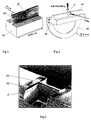
- a sample piece 12 is removed from the solid material, for example from a semiconductor wafer, and a web 11 is worked out on it by mechanical sawing, as is shown, for example, in FIG. 1.
- the sample 12 is about 2600 microns long and the web width is about 20 microns.
- a protective coating is applied to the end face of the web 11 in a partial area where the lamella sample 5 is to be produced, which serves as a mask for the lamella 5 lying underneath and to be etched out. With a focused ion beam (which strikes the web on the end face) FIB), the lamella 5 is now exposed by deep etching.
- a focused ion beam which strikes the web on the end face
- FIG. 2 this is shown schematically by the arrow with the inscription "FIB-etching".
- the sample piece 12 with the lamella sample 5 is now arranged on a sample holder 10 with a diameter of, for example, 3 mm and can now be viewed in the TEM, as is also indicated schematically in FIG. 2 with the arrow and the associated inscription "TEM".
- 3 shows a scanning electron microscopic (SEM) image reproduction of such a sample 5 for better illustration. It can also be seen from this that the FIB etched lamella-like sample (FIB etching) is relatively thick.
- a high waviness of the material can be seen, which also shows that contamination occurs during the etching or sputtering process due to re-covering of the surfaces 6a, b involved.
- the screened FIB ion beam must be operated with energies between 5 keV to 30 keV because of the necessary focusing. This leads to corresponding damage or disruption of the material structure on both sides of the lamella surfaces 6a and 6b of the sample 5, typically to depths of approximately 20 nm.
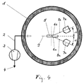
- an FIB sample which already has a corresponding lamella structure 5 is now arranged in a vacuum recipient 1 in its sample arrangement axis or plane 9 in order to be subsequently treated there accordingly.
- the recipient 1 is evacuated in a known manner via a pump line 2 with a vacuum pump 3, for example a turbo-vacuum pump, with a pump outlet 4.
- a vacuum pump 3 for example a turbo-vacuum pump
- an ion source 7 is arranged in the vacuum chamber 1, which can be directed obliquely at an angle ⁇ with respect to the sample arrangement plane 9 with its ion beam 8 onto the sample surfaces 6a and 6b.
- the sample 5 can be etched on both sides of its surfaces 6a and 6b with the ion source 7 by the ion bombardment and can thus be thinned to the desired extent.
- the ion beam 8 is to be directed alternately 8a, b both to one side 6a and to the other side 6b of the sample 5. This mutual etching of the two sides of the sample 6a, b prevents re-loading and thus contamination of the surfaces 6a, b.
- the mutual etching of the surfaces 6a and 6b is advantageously carried out by periodically changing the sides of the sample 5.
- a bombardment angle range +/- ⁇ has to be run through according to the invention, which runs through the values in the range +/- 4 ° to +/- 45 °.
- Particularly good results are achieved for the shot angle range +/- ⁇ in the range +/- 4 ° to +/- 20 °.
- care must be taken that each side of the sample is processed at least twice with the ion beam. However, it is particularly advantageous if each side of the sample is processed several times. The duration of the exposure to radiation per processing step depends on the initial thickness and the amount of material to be thinned.
- the known FIB samples and the desired results are advantageously carried out in a range from a few seconds to a few minutes per side and step. According to the invention, as much as possible should be removed from the disturbed structural area of the FIB sample surface 6a, b.
- the maximum remaining interference depth of the two surfaces 6a, b should have a maximum of 10 nm after processing, whereby according to the inventive procedure preferably a maximum of 5 nm disturbed material should remain on the surfaces 6a, b.
- Such high-resolution samples for HRTEM use are especially for sample materials in the range of semiconductor examinations, in particular for semiconductors, the materials contain suitable as Si, GaAs, Ge.
- the aftertreatment according to the invention can also be particularly good be automated by using corresponding programmable Controls.
- the timing, the number of etching steps and the firing angle, as well as the movement course preset as desired or programmed and processed automatically become.
- the entire preparation process can thus automated with the help of a preparation program and individually to the samples to be created 5 can be adjusted.
- the automatic aftertreatment of Sample 5 does not therefore require the constant presence of the Operator and is therefore time-saving, reproducible and economically feasible.
- FIB-Schhitt or Slat 5 made of silicon material with a platinum protective layer 13 used.
- the lamella is 6 ⁇ m deep including the platinum protective layer 13 and 13 ⁇ m wide.
- the acceleration voltage of the Ion source 7 was 2 keV and the ion current was 1.3 mA.
- the changing firing angle +/- ⁇ of maximum +/- 15 ° the sample was +/- 20 ° with respect to the lamella surface oscillates, i.e. with respect to the direction of the ion beam tilts back and forth in intervals of approximately 0.1 Hz, in the preferred direction to avoid the etching beam on the sample.
- the sample was first etched for a total of eight minutes then looked at and then etched on for ten minutes and also looked at and finally again with three minutes further etched, i.e. etched for a total of 21 minutes.
Abstract
Description
Die Erfindung bezieht sich auf eine TEM-FIB-Probe gemäss
Oberbegriff nach Anspruch 1 sowie auf ein Verfahren zur
Herstellung einer solchen Probe gemäss Oberbegriff nach Anspruch
7.The invention relates to a TEM-FIB sample according to
The preamble of
Proben wird für die Transmissions-Elektronen-Mikroskopie
(TEM) können auf verschiedene Art präpariert werden. Um
Proben mit einem TEM betrachten zu können, müssen diese
entsprechend definiert gedünnt werden, so dass diese im TEM
durchstrahlt werden können. Hierbei ist die Qualität der
Bildauflösung ganz wesentlich von der Qualität der Probe
abhängig. Dafür sollte die Probe auf eine entsprechend gewünschte,
definierte Dicke gleichförmig eingestellt werden
durch einen entsprechenden Ätzvorgang. Hierbei ist es wichtig,
dass bei diesem Ätzvorgang die Probenstruktur nicht
durch den Vorgang selbst verändert wird. Dies führt allerdings
nicht zu der gewünschten Qualität der Probe entsprechend
den heutigen Anforderungen. Die nasschemische Ätzmethode
ist diesbezüglich nicht ziehlführend.
Aus diesem Grunde werden für die hochqualitativen TEM-Proben
heute die Proben mit einem fixierten Argon-Ionen-Strahl,
der etwa einen Durchmesser von ca. 1 mm aufweist,
durch Ätzen bearbeitet. Eine weitere bekannte und heute bevorzugte
Methode besteht darin, mit einem fokussierten Ionenstrahl
(FIB-Technik) die Probe herauszuarbeiten und
wunschgemäss zu dünnen. Hierbei wird ein gerasterter, fein
fokussierter Gallium-Ionen-Strahl mit einem Strahldurchmesser
von wenigen nm eingesetzt, mit dessen Hilfe TEM-Proben
lamellenförmig, durch senkrechten Beschuss der Oberfläche,
aus dem Festmaterial herauspräpariert werden können. Typischerweise
sind hierbei die Probenlamellen etwa 80 bis 100
nm dick. Diese neueste FIB-Präparations-Technik ist beispielsweise
beschrieben in P. Gnauck, P. Hoffrogge, ICEM
15, Durban, (Supply 1: Proceedings), (2002) 3,32.Samples for transmission electron microscopy (TEM) can be prepared in different ways. In order to be able to view samples with a TEM, they have to be thinned accordingly so that they can be irradiated in the TEM. The quality of the image resolution is very much dependent on the quality of the sample. For this purpose, the sample should be set uniformly to a correspondingly desired, defined thickness by means of an appropriate etching process. It is important that the sample structure is not changed by the process itself during this etching process. However, this does not lead to the desired quality of the sample according to today's requirements. In this regard, the wet chemical etching method is not leading.
For this reason, for the high-quality TEM samples, the samples are processed with a fixed argon ion beam, which has a diameter of approximately 1 mm, by etching. Another known and preferred method today is to work out the sample with a focused ion beam (FIB technique) and to thin it as desired. Here, a screened, finely focused gallium ion beam with a beam diameter of a few nm is used, with the help of which TEM samples can be prepared from the solid material by lamellar bombardment of the surface. The sample lamellae are typically about 80 to 100 nm thick. This latest FIB preparation technique is described, for example, in P. Gnauck, P. Hoffrogge, ICEM 15, Durban, (Supply 1: Proceedings), (2002) 3.32.
Die Technik zur Herstellung von FIB-Proben für TEM-Lamellen weist allerdings verschiedene Nachteile auf. Die Lamelle kann nicht so dünn präpariert werden, dass die Proben für die hochauflösende Transmissions-Elektronen-Mikroskopie (HRTEM) gut geeignet wäre. Die TEM-Lamelle wird ausserdem durch die Präparation kontaminiert und weist im Vergleich zur konventionellen Ionenstral-Präparation, mit fixiertem Jonenstrahl, wesentlich höhere Randamorphisierungen auf. Diese Randamorphisierung ist eine Störung der ursprünglichen Struktur in der Oberfläche der Probe und zwar auf beiden Seiten der Probe und dies bis in Tiefen von etwa 20 nm auf beiden Seiten der Probe. Bei konventioneller Probenherstellung mittels fixiertem Ionenstrahl-Ätzen reicht diese Zerstörung der ursprünglichen Struktur nur etwa bis 5 nm Tiefe, wobei allerdings die Vorteile, wie beispielsweise die Zielgenauigkeit, der gerasterten FIB-Technik nicht erzielt werden können.The technology for producing FIB samples for TEM lamellae has several disadvantages, however. The slat can not be prepared so thin that the samples for high-resolution transmission electron microscopy (HRTEM) would be well suited. The TEM lamella is also contaminated by the preparation and compares for conventional ion beam preparation, with fixed Ion beam, much higher edge amorphizations. This edge amorphization is a perturbation of the original one Structure in the surface of the sample on both Sides of the sample and this to depths of about 20 nm on both sides of the sample. With conventional sample production this is sufficient by means of fixed ion beam etching Destruction of the original structure only up to about 5 nm Depth, but with the advantages such as the target accuracy of the rasterized FIB technology is not achieved can be.
Die vorerwähnten Probleme führen zu einer stark verminderten Probenqualität. Um diese Probleme lösen zu können, wurden in letzter Zeit Versuche unternommen, die FIB-Proben mit Hilfe der konventionellen nichtgerasterten Ionenstrahl-Präparation nachzudünnen. Aufgrund der Probengeometrie und der einseitigen Ätzung der Lamelle kommt es aber zu zusätzlichen, unerwünschten Kontaminationen. Solche Kontaminationen machen den Vorteil der Nachbehandlung zunichte und die Probe unbrauchbar. Die Problematik der Nachbearbeitung von FIB-Proben ist im Stand der Technik beschrieben bei Max V. Siderov, Microsc. Microanal.8 (Suppl 2: Proceedings), (2002) 560 CD.The aforementioned problems lead to a greatly reduced Sample quality. In order to solve these problems, Attempts have recently been made to sample the FIB with the help of conventional non-rastered ion beam preparation nachzudünnen. Due to the sample geometry and the one-sided etching of the lamella leads to additional, unwanted contamination. Such contamination destroy the advantage of aftertreatment and the Sample unusable. The problem of postprocessing FIB samples are described in the prior art at Max V. Siderov, Microsc. Microanal. 8 (Suppl 2: Proceedings), (2002) 560 CD.
Der Erfindung liegt die Aufgabe zugrunde, die Nachteile des Standes der Technik zu beseitigen, insbesondere aber TEM-Proben zu realisieren, welche eine hohe Qualität ermöglichen, insbesondere aber eine hohe Auflösung und Detailwiedergabe bei Betrachtung mit dem TEM ermöglichen.The invention has for its object the disadvantages of Eliminate prior art, but especially TEM samples to realize, which enable high quality, but especially high resolution and detail reproduction enable when viewed with the TEM.
Die Aufgabe wird erfindungsgemäss durch die Vorrichtung
nach Anspruch 1 gelöst und durch Vorgehen nach dem Verfahren
nach Anspruch 7. Die abhängigen Ansprüche definieren
weitere vorteilhafte Ausführungsformen und Verfahrensschritte.According to the invention, the object is achieved by the device
solved according to
Die erfindungsgemässe Ausbildung einer Probe, insbesondere
einer Probenlamelle, ermöglicht die Herstellung einer genügend
dünnen Lamelle, welche bei der TEM-Betrachtung einen
hohen Detaillierungsgrad des ursprünglichen Probenmateriales
auflösen und abbilden kann. Hierzu wird erfindungsgemäss
eine mit der FIB-Technik hergestellte Grobprobe mit
einem Ionenstrahl nachbearbeitet und auf die erforderliche
Dicke gedünnt beziehungsweise geätzt. Die Nachbearbeitung
der Probe muss hierbei kontaminationsfrei sein, das heisst
es darf kein Fremdmaterial, wie Umgebungsmaterial oder vom
ursprünglichen Material während des Ätzvorganges wieder auf
der Probe deponiert werden. Ein weiterer wichtiger Aspekt
besteht darin, dass bei dieser Nachbearbeitung die Materialstruktur
der Probe an der Oberfläche nicht verändert
wird, beziehungsweise die ursprüngliche Struktur des Probenmateriales
erhalten bleibt. Da die FIB-Probe als Ausgangsprobe
bereits an den Oberflächen Strukturstörungen wie
Randamorphisierungen aufweist, die inhärent sind mit der
FIB-Technik und etwa 20 nm tief in jede Probenseite hineinreichen,
ist es notwendig, dass die Nachbearbeitungstechnik
solche Störungsbereiche zu einem wesentlichen Teil eliminieren
kann, um das ursprüngliche nicht beeinflusste Material,
welches analysiert werden soll, freizulegen. Erfindungsgemäss
wird dies dadurch erreicht, indem die Probe
durch einen Ionenstrahl unter einem Beschusswinkel wechselseitig
auf beiden Seiten beschossen und abgetragen wird.
Dadurch ist es möglich, Kontaminationen weitestgehend zu
vermeiden, welche für die hochauflösende Transmissions-Elektronen-Mikroskopie
(HRTEM) zwingend notwendig ist. Das
erfindungsgemässe Verfahren erlaubt nun auch die für diese
hochauflösende Technologie benötigten und geeignet dünnen
Proben herzustellen von weniger als 40 nm Dicke, ja sogar
vorzugsweise von weniger als 20 nm Dicke. Ein weiterer Vorteil
besteht darin, dass die erfindungsgemässe Nachbearbeitung
für alle FIB-Probenarten anwendbar ist und nicht von
der Probengeometrie abhängig ist. Es können also auch komplizierte
Probengeometrien nachgearbeitet werden.
Um Vorzugsrichtungen der Jonenstrahlätzung, also unerwünschte
riefen artige Strukturen, an der Probenoberfläche
zu vermeiden ist es vorteilhaft die Probe gegenüber dem Jonenstrahl
zusätzlich zu bewegen. Solche Bewegungen können
oszillierend sein und als periodische Kippbewegung der Probe
gegenüber der Jonenstrahleinfallsrichtung ausgeführt
werden. Diese Bewegung sollte relativ langsam und gleichmässig
sein. Die Verkippung kann hierbei vorteilhaft bis um
einen Winkel von +- 70 Grad gegenüber der Jonenstrahlrichtung
erfolgen und die Bewegungsfrequenz etwa im Bereich von
0,1 Hz. The design according to the invention of a sample, in particular a sample lamella, enables the production of a sufficiently thin lamella which, when viewed by TEM, can resolve and display a high level of detail of the original sample material. For this purpose, according to the invention, a coarse sample produced using the FIB technique is reworked with an ion beam and thinned or etched to the required thickness. The post-processing of the sample must be contamination-free, i.e. no foreign material such as surrounding material or the original material may be deposited on the sample again during the etching process. Another important aspect is that the material structure of the sample on the surface is not changed during this post-processing, or the original structure of the sample material is retained. Since the FIB sample as a starting sample already shows structural defects such as edge amorphizations on the surfaces, which are inherent with the FIB technique and extend approximately 20 nm deep into each sample side, it is necessary that the post-processing technique can largely eliminate such interference areas, to expose the original unaffected material to be analyzed. This is achieved according to the invention in that the sample is bombarded and removed alternately on both sides by an ion beam at a bombardment angle. This makes it possible to largely avoid contamination, which is absolutely necessary for high-resolution transmission electron microscopy (HRTEM). The method according to the invention now also allows the thin samples of less than 40 nm thickness, even preferably preferably less than 20 nm thickness, required and suitable for this high-resolution technology. Another advantage is that the post-processing according to the invention can be used for all types of FIB samples and is not dependent on the sample geometry. Complicated sample geometries can also be reworked.
In order to avoid preferred directions of the ion beam etching, that is to say undesired, ridge-like structures, on the sample surface, it is advantageous to additionally move the sample relative to the ion beam. Such movements can be oscillating and can be carried out as a periodic tilting movement of the sample with respect to the ion beam incidence direction. This movement should be relatively slow and steady. The tilting can advantageously take place up to an angle of + - 70 degrees with respect to the ion beam direction and the movement frequency approximately in the range of 0.1 Hz.
Die Erfindung wird nun nachfolgend beispielsweise und anhand von schematischen Zeichnungen näher erläutert. Es zeigen:
- Fig. 1
- einen mechanische Präparationsschritt zur Herstellung einer FIB - Probe gemäss Stand der Technik
- Fig. 2
- eine Halterung und die FIB - Bearbeitung des Präparates gemäss Fig. 1 nach Stand der Technik
- Fig. 3
- eine dreidimensionale Darstellung einer fertigen FIB - Probe in einer REM - Aufnahme gemäss Stand der Technik
- Fig. 4
- eine Anordnung zur erfindungsgemässen Nachbehandlung einer FIB - Probe
- Fig. 1
- a mechanical preparation step for producing a FIB sample according to the prior art
- Fig. 2
- a holder and the FIB processing of the preparation according to FIG. 1 according to the prior art
- Fig. 3
- a three-dimensional representation of a finished FIB sample in a SEM image according to the prior art
- Fig. 4
- an arrangement for the aftertreatment of a FIB sample according to the invention
Zur Herstellung einer FIB-Probe wird aus dem Festkörpermaterial,
beispielsweise aus einem Halbleiterwafer, ein Probenstück
12 entnommen und an diesem durch mechanisches Sägen
ein Steg 11 herausgearbeitet, wie dies beispielsweise
in Fig. 1 dargestellt ist. Hierbei ist beispielsweise das
Probenstück 12 etwa 2600 µm lang und die Stegbreite etwa 20
µm. Auf der Stirnseite des Steges 11 wird in einem Teilbereich,
wo die Lamellenprobe 5 erzeugt werden soll, eine
Schutzbeschichtung aufgebracht, welche als Maskierung dient
für die darunter liegende und herauszuätzende Lamelle 5.
Mit einem senkrecht stirnseitig auf den Steg auftreffenden
Focussed-Ion-Beam (FIB) wird nunmehr die Lamelle 5 durch
Tiefenätzen frei gelegt. In Fig. 2 ist dies schematisch gezeigt
durch die Pfeilangabe mit der Beschriftung "FIB-etching".
Das Probenstück 12 mit der Lamellenprobe 5 wird nun auf einem
Probenhalter 10 mit einem Durchmesser von beispielsweise
3 mm angeordnet und kann nun im TEM betrachtet werden,
wie dies ebenfalls schematisch in Fig. 2 mit dem Pfeil und
der dazugehörigen Beschriftung "TEM" angedeutet ist.
In Fig. 3 ist eine Raster - elektronenmikroskopische (REM)
Bildwiedergabe einer solchen Probe 5 gezeigt zur besseren
Veranschaulichung. Daraus ist auch ersichtlich, dass die
FIB geätzte Lamellen artige Probe (FIB-etching) relativ
dick ist. Im Tiefenbereich der Probe sieht man eine hohe
Welligkeit des Materiales, welches auch zeigt, dass bei dem
Ätz- respektive Zerstäubungsvorgang Kontaminationen auftreten
durch Wiederbelegung der beteiligten Oberflächen 6a,b.
Der gerasterte FIB-Ionenstrahl muss mit Energien zwischen 5
keV bis 30 keV wegen der notwendigen Fokussierung betrieben
werden. Dies führt zu entsprechenden Schäden beziehungsweise
Störungen der Materialstruktur beidseitig der Lamellenoberflächen
6a und 6b der Probe 5, typischerweise bis Tiefen
von etwa 20 nm.To produce an FIB sample, a
The
3 shows a scanning electron microscopic (SEM) image reproduction of such a
Erfindungsgemäss wird nunmehr eine FIB-Probe, die bereits
eine entsprechenden Lamellenstruktur 5 aufweist, in einem
Vakuumrezipienten 1 angeordnet in ihrer Probenanordnungsachse
beziehungsweise -ebene 9, um dort entsprechend nachbehandelt
zu werden. Der Rezipient 1 wird auf bekannte Weise
über eine Abpumpleitung 2 mit einer Vakuumpumpe 3, beispielsweise
einer Turbo-Vakuumpumpe, mit Pumpauslass 4 evakuiert.
In der Vakuumkammer 1 ist ausserdem eine Ionenquelle
7 angeordnet, welche schräg unter einem Winkel α gegenüber
der Probenanordnungsebene 9 mit ihrem Ionenstrahl 8
auf die Probenoberflächen 6a und 6b gerichtet werden kann.
Die Probe 5 kann mit der Ionenquelle 7 durch den Ionenbeschuss
beidseitig an ihren Oberflächen 6a und 6b geätzt
werden und somit auf das gewünschte Mass gedünnt werden.
Erfindungsgemäss soll der Ionenstrahl 8 abwechslungsweise
8a,b sowohl auf die eine Seite 6a wie auch auf die andere
Seite 6b der Probe 5 gerichtet werden. Durch dieses wechselseitige
Ätzen der beiden Probenseiten 6a,b kann eine
Wiederbelegung und somit eine Kontamination der Oberflächen
6a,b vermieden werden. Das wechselseitige Ätzen der Oberflächen
6a und 6b erfolgt vorteilhafterweise durch ein periodisches
Wechseln der Seiten der Probe 5. Dies kann sowohl
durch hin- und herbewegen 7a,b der Ionenquelle 7 um
die Probenanordnungsachse 9 erfolgen, wie auch um entsprechende
Kippbewegungen der Probe 5 selbst bei stehender Ionenquelle
7. Massgeblich ist hierbei das wechselseitige Ätzen
der Probenoberflächen 6a und 6b, welches mit einer Relativbewegung
zwischen der Richtung des Ionenstrahles 8 und
der Oberflächen 6a und 6b der Probe 5 erzielt werden kann.
Der Ionenstrahl 8 mit seinen Positionen 8a und 8b soll
hierbei schräg auf die Probenoberflächen 6a und 6b auftreffen
entsprechend dem dargestellten Beschusswinkel +α und
-α gegenüber der Probenanordnungsebene 9. Die wechselseitige
Behandlung der Probenoberflächen 6a und 6b werden vorteilhafterweise
durch pendelartige Relativbewegung um den
Winkelbereich +α/-α ausgeführt. Hierbei durchläuft der Ionenstrahl
auch den Nullgrad-Winkel, welcher mit der Probenanordnungsebene
9 zusammen fällt. Kontaminationen der Probe
5 werden hierdurch wirkungsvoll vermieden. Um hierzu gute
Ergebnisse zu erreichen, ist erfindungsgemäss ein Beschusswinkelbereich
+/-α zu durchlaufen, der die Werte im Bereich
+/- 4° bis +/- 45° durchläuft. Besonders gute Ergebnisse
werden erreicht für den Beschusswinkelbereich +/-α
im Wertebereich +/- 4° bis +/- 20°.
Bei der wechselseitigen Bearbeitung ist darauf zu achten,
dass jede Seite der Probe mindestens zwei mal mit dem Jonenstrahl
bearbeitet wird. Besonders von Vorteil ist allerdings,
wenn jede Seite der Probe mehrere male bearbeitet
wird. Die Zeitdauer der Strahleinwirkung pro Bearbeitungsschritt
hängt von der Ausgangsdicke und der Menge des ab zu
dünnenden Materiales ab. Bei den bekannten FIB-Proben und
den gewünschten Ergebnissen wird vorteilhafterweise in einem
Bereich von einigen Sekunden bis einigen Minuten pro
Seite und Schritt gearbeitet.
Vom gestörten Strukturbereich der FIB-Proben-Oberfläche
6a,b soll erfindungsgemäss möglichst viel abgetragen werden.
Die maximal verbleibende Störtiefe der beiden Oberflächen
6a,b soll nach der Bearbeitung maximal 10 nm aufweisen,
wobei gemäss erfindungsgemässem Vorgehen vorzugsweise
maximal 5 nm gestörtes Material an den Oberflächen 6a,b übrig
bleiben soll.According to the invention, an FIB sample which already has a
In the case of mutual processing, care must be taken that each side of the sample is processed at least twice with the ion beam. However, it is particularly advantageous if each side of the sample is processed several times. The duration of the exposure to radiation per processing step depends on the initial thickness and the amount of material to be thinned. The known FIB samples and the desired results are advantageously carried out in a range from a few seconds to a few minutes per side and step.
According to the invention, as much as possible should be removed from the disturbed structural area of the FIB sample surface 6a, b. The maximum remaining interference depth of the two surfaces 6a, b should have a maximum of 10 nm after processing, whereby according to the inventive procedure preferably a maximum of 5 nm disturbed material should remain on the surfaces 6a, b.
Solche hochauflösende Proben für den HRTEM-Einsatz, die weniger als 40 nm dick sind oder gar vorzugsweise weniger als 20 nm dick, sind besonders für Probenmaterialien im Bereich von Halbleiteruntersuchungen insbesondere für Halbleiter, die Materialien enthalten wie Si, GaAs, Ge geeignet.Such high-resolution samples for HRTEM use, the less are thicker than 40 nm or even less than 20 nm thick, are especially for sample materials in the range of semiconductor examinations, in particular for semiconductors, the materials contain suitable as Si, GaAs, Ge.
Die Nachbehandlung kann erfindungsgemäss auch besonders gut
automatisiert werden durch Einsatz von entpsrechenden programmierbaren
Steuerungen. Hierbei kann sowohl der Zeittakt,
die Anzahl der Ätzschritte und der Beschusswinkel,
wie auch der Bewegungsverlauf wunschgemäss voreingestellt
beziehungsweise programmiert werden und automatisch abgewickelt
werden. Der gesamte Präparationsvorgang kann somit
mit Hilfe eines Präparationsprogrammes entsprechend automatisiert
werden und individuell auf die zu erstellenden Proben
5 angepasst werden. Die automatische Nachbehandlung von
Proben 5 verlangt somit nicht die ständige Anwesenheit des
Bedieners und ist dadurch zeitsparend, reproduzierbar und
wirtschaftlich realisierbar.The aftertreatment according to the invention can also be particularly good
be automated by using corresponding programmable
Controls. The timing,
the number of etching steps and the firing angle,
as well as the movement course preset as desired
or programmed and processed automatically
become. The entire preparation process can thus
automated with the help of a preparation program
and individually to the samples to be created
5 can be adjusted. The automatic aftertreatment of
Zur weiteren Verdeutlichung wird die erfindungsgemässe
Nachbearbeitung einer FIB-Probe anhand eines Beispieles beschrieben.
Als Ausgangsmaterial wird ein FIB-Schhitt beziehungsweise
Lamelle 5 aus Silizium-Material mit einer Platin-Schutzschicht
13 verwendet. Die Lamelle ist 6 µm tief
inklusive der Platin-Schutzschicht 13 und 13 µm breit. Für
die erfindungsgemässe Nachdünnung wurde eine Ionen-Dünnung
verwendet in einer Anlage RES 100 der Baltec AG, FL-9496
Balzers, Liechtenstein, welche für diese Anwendung besonders
geeignet ist. Es wurde ein Ätzprogramm verwendet, welches
einen automatischen Wechsel der Beschussrichtung der
Ionenquelle ermöglichte. Der Probenhalter wurde jeweils
nach einer Minute von der Position +α = 15° zu der Position
-α = -15° gewechselt. Die Beschleunigungsspannung der
Ionenquelle 7 betrug 2 keV und der Ionenstrom 1,3 mA. Neben
dem wechselnden Beschusswinkel +/- α von maximal +/- 15°
bezüglich der Lamellenoberfläche wurde die Probe um +/- 20°
oszilliert, also gegenüber der Jonenstrahleinfallsrichtung
hin und her vekippt im Takt von etwa o,1 Hz, um Vorzugsrichtung
des Ätzstrahles an der Probe zu vermeiden. Die Musterprobe
wurde zuerst insgesamt acht Minuten lang geätzt,
dann betrachtet und dann mit zehn Minuten weitergeätzt und
ebenfalls betrachtet und zuletzt nochmals mit drei Minuten
weitergeätzt, also insgesamt 21 Minuten lang geätzt. Im Ergebnis
konnten Proben erreicht werden, die bereits nach dem
ersten Schritt dünner als 40 nm waren und nach den weiteren
Schritten bereits im Bereich von 20 nm und darunter ohne
wesentliche Kontamination der Oberflächen. In der Folge
konnten entsprechend dem erfindungsgemässen Vorgehen hochauflösende
und detailgetreue TEM-Bilder erzielt werden.The inventive method is used for further clarification
Post-processing of a FIB sample is described using an example.
An FIB-Schhitt or
Claims (17)
Applications Claiming Priority (2)
| Application Number | Priority Date | Filing Date | Title |
|---|---|---|---|
| CH2252003 | 2003-02-15 | ||
| CH2252003 | 2003-02-15 |
Publications (1)
| Publication Number | Publication Date |
|---|---|
| EP1447656A1 true EP1447656A1 (en) | 2004-08-18 |
Family
ID=32661009
Family Applications (1)
| Application Number | Title | Priority Date | Filing Date |
|---|---|---|---|
| EP20030029595 Withdrawn EP1447656A1 (en) | 2003-02-15 | 2003-12-23 | Specimens for transmission electron microscope |
Country Status (3)
| Country | Link |
|---|---|
| US (1) | US7002152B2 (en) |
| EP (1) | EP1447656A1 (en) |
| JP (1) | JP2004245841A (en) |
Cited By (3)
| Publication number | Priority date | Publication date | Assignee | Title |
|---|---|---|---|---|
| WO2008106815A3 (en) * | 2007-03-06 | 2008-10-23 | Bal Tec Ag | Method for the production of a sample for electron microscopy |
| EP2674742A3 (en) * | 2012-06-11 | 2014-02-12 | Fei Company | Lamella creation method and device using fixed-angle beam and rotating sample stage |
| CN104101510A (en) * | 2013-04-04 | 2014-10-15 | 弗劳恩霍弗应用技术研究院 | Method and arrangement for manufacturing a sample for microstructural materials diagnostics and corresponding sample |
Families Citing this family (28)
| Publication number | Priority date | Publication date | Assignee | Title |
|---|---|---|---|---|
| US8058142B2 (en) | 1996-11-04 | 2011-11-15 | Besang Inc. | Bonded semiconductor structure and method of making the same |
| JP4335497B2 (en) * | 2002-07-12 | 2009-09-30 | エスアイアイ・ナノテクノロジー株式会社 | Ion beam apparatus and ion beam processing method |
| US7799675B2 (en) * | 2003-06-24 | 2010-09-21 | Sang-Yun Lee | Bonded semiconductor structure and method of fabricating the same |
| US7632738B2 (en) * | 2003-06-24 | 2009-12-15 | Sang-Yun Lee | Wafer bonding method |
| US20100190334A1 (en) * | 2003-06-24 | 2010-07-29 | Sang-Yun Lee | Three-dimensional semiconductor structure and method of manufacturing the same |
| US8471263B2 (en) | 2003-06-24 | 2013-06-25 | Sang-Yun Lee | Information storage system which includes a bonded semiconductor structure |
| TW200500599A (en) * | 2003-06-24 | 2005-01-01 | Au Optronics Corp | OLED electron microscope test specimen and its manufacturing method |
| US7867822B2 (en) | 2003-06-24 | 2011-01-11 | Sang-Yun Lee | Semiconductor memory device |
| US8071438B2 (en) | 2003-06-24 | 2011-12-06 | Besang Inc. | Semiconductor circuit |
| US7863748B2 (en) * | 2003-06-24 | 2011-01-04 | Oh Choonsik | Semiconductor circuit and method of fabricating the same |
| US20060219919A1 (en) * | 2003-11-11 | 2006-10-05 | Moore Thomas M | TEM sample holder and method of forming same |
| US8723144B2 (en) * | 2004-07-14 | 2014-05-13 | Applied Materials Israel, Ltd. | Apparatus for sample formation and microanalysis in a vacuum chamber |
| JP4486462B2 (en) * | 2004-09-29 | 2010-06-23 | 日本電子株式会社 | Sample preparation method and sample preparation apparatus |
| US8367524B2 (en) * | 2005-03-29 | 2013-02-05 | Sang-Yun Lee | Three-dimensional integrated circuit structure |
| US8455978B2 (en) | 2010-05-27 | 2013-06-04 | Sang-Yun Lee | Semiconductor circuit structure and method of making the same |
| EP2095134B1 (en) | 2006-10-20 | 2017-02-22 | FEI Company | Method and apparatus for sample extraction and handling |
| JP5270558B2 (en) | 2006-10-20 | 2013-08-21 | エフ・イ−・アイ・カンパニー | Method and sample structure for creating S / TEM sample |
| EP2151848A1 (en) | 2008-08-07 | 2010-02-10 | FEI Company | Method of machining a work piece with a focused particle beam |
| DE102009008166A1 (en) | 2009-02-10 | 2010-09-02 | Carl Zeiss Nts Gmbh | Method for manufacturing blade, involves activating surface area of substrate for producing protective strip, where protective strip is deposited on activated surface area by gas-phase deposition |
| US8723335B2 (en) | 2010-05-20 | 2014-05-13 | Sang-Yun Lee | Semiconductor circuit structure and method of forming the same using a capping layer |
| DE102010032894B4 (en) | 2010-07-30 | 2013-08-22 | Carl Zeiss Microscopy Gmbh | Tem lamella, process for its preparation and apparatus for carrying out the process |
| US8624185B2 (en) * | 2010-09-17 | 2014-01-07 | Carl Zeiss Microscopy, Llc | Sample preparation |
| JP5657435B2 (en) * | 2011-03-15 | 2015-01-21 | 日本電子株式会社 | Thin film sample preparation method |
| US9360401B2 (en) * | 2014-09-24 | 2016-06-07 | Inotera Memories, Inc. | Sample stack structure and method for preparing the same |
| US20160189929A1 (en) * | 2014-10-29 | 2016-06-30 | Omniprobe, Inc. | Rapid tem sample preparation method with backside fib milling |
| CN104913957B (en) * | 2015-05-04 | 2019-07-19 | 中国石油化工股份有限公司 | TEM home position observation material matrix/passivating film interfacial structure sample preparation methods |
| CN113804521B (en) * | 2020-06-16 | 2022-12-13 | 中国科学院上海硅酸盐研究所 | Sample table for preparing ultrathin sample |
| CN113899764A (en) * | 2021-09-27 | 2022-01-07 | 中国科学院广州地球化学研究所 | Sample preparation method for electron microscopic three-dimensional reconstruction geological sample based on ion thinning |
Citations (6)
| Publication number | Priority date | Publication date | Assignee | Title |
|---|---|---|---|---|
| US4128765A (en) * | 1976-10-29 | 1978-12-05 | Joseph Franks | Ion beam machining techniques and apparatus |
| US5009743A (en) * | 1989-11-06 | 1991-04-23 | Gatan Incorporated | Chemically-assisted ion beam milling system for the preparation of transmission electron microscope specimens |
| US5472566A (en) * | 1994-11-14 | 1995-12-05 | Gatan, Inc. | Specimen holder and apparatus for two-sided ion milling system |
| US5986264A (en) * | 1995-04-29 | 1999-11-16 | Bal-Tec A.G. | Ion beam preparation device for electron microscopy |
| US6194720B1 (en) * | 1998-06-24 | 2001-02-27 | Micron Technology, Inc. | Preparation of transmission electron microscope samples |
| US6218663B1 (en) * | 1995-07-25 | 2001-04-17 | Nmi Naturwissenschaftliches Und Medizinisches | Process and device for ion thinning in a high resolution transmission electron microscope |
Family Cites Families (2)
| Publication number | Priority date | Publication date | Assignee | Title |
|---|---|---|---|---|
| US6039000A (en) * | 1998-02-11 | 2000-03-21 | Micrion Corporation | Focused particle beam systems and methods using a tilt column |
| US6768110B2 (en) * | 2000-06-21 | 2004-07-27 | Gatan, Inc. | Ion beam milling system and method for electron microscopy specimen preparation |
-
2003
- 2003-04-10 US US10/410,828 patent/US7002152B2/en not_active Expired - Lifetime
- 2003-12-23 EP EP20030029595 patent/EP1447656A1/en not_active Withdrawn
-
2004
- 2004-02-12 JP JP2004035289A patent/JP2004245841A/en active Pending
Patent Citations (6)
| Publication number | Priority date | Publication date | Assignee | Title |
|---|---|---|---|---|
| US4128765A (en) * | 1976-10-29 | 1978-12-05 | Joseph Franks | Ion beam machining techniques and apparatus |
| US5009743A (en) * | 1989-11-06 | 1991-04-23 | Gatan Incorporated | Chemically-assisted ion beam milling system for the preparation of transmission electron microscope specimens |
| US5472566A (en) * | 1994-11-14 | 1995-12-05 | Gatan, Inc. | Specimen holder and apparatus for two-sided ion milling system |
| US5986264A (en) * | 1995-04-29 | 1999-11-16 | Bal-Tec A.G. | Ion beam preparation device for electron microscopy |
| US6218663B1 (en) * | 1995-07-25 | 2001-04-17 | Nmi Naturwissenschaftliches Und Medizinisches | Process and device for ion thinning in a high resolution transmission electron microscope |
| US6194720B1 (en) * | 1998-06-24 | 2001-02-27 | Micron Technology, Inc. | Preparation of transmission electron microscope samples |
Non-Patent Citations (3)
| Title |
|---|
| AKIRA YAMAGUCHI ET AL: "TRANSMISSION ELECTRON MICROSCOPY SPECIMEN PREPARATION TECHNIQUE USING FOCUSED ION BEAM FABRICATION: APPLICATION TO GAAS METAL- SEMICONDUCTOR FIELD EFFECT TRANSISTORS", JOURNAL OF VACUUM SCIENCE AND TECHNOLOGY: PART B, AMERICAN INSTITUTE OF PHYSICS. NEW YORK, US, vol. 11, no. 6, 1 November 1993 (1993-11-01), pages 2016 - 2020, XP000423384, ISSN: 0734-211X * |
| ASSAYAG G B ET AL: "LOCALIZED THINNING OF GAAS/GAALAS NANOSTRUCTURES BY A COMBINED SCANNING ELECTRON MICROGRAPH/FOCUS ION BEAM SYSTEM FOR HIGH-QUALITY CROSS-SECTIONAL TRANSMISSION ELECTRON MICROSCOPY SAMPLES", JOURNAL OF VACUUM SCIENCE AND TECHNOLOGY: PART B, AMERICAN INSTITUTE OF PHYSICS. NEW YORK, US, vol. 11, no. 3, 1 May 1993 (1993-05-01), pages 531 - 535, XP000383150, ISSN: 0734-211X * |
| ISHITANI T ET AL: "FOCUSED ION BEAM SYSTEM FOR TEM SAMPLE PREPARATION", HITACHI REVIEW, HITACHI LTD. TOKYO, JP, vol. 45, no. 1, 1 February 1996 (1996-02-01), pages 19 - 24, XP000593685, ISSN: 0018-277X * |
Cited By (5)
| Publication number | Priority date | Publication date | Assignee | Title |
|---|---|---|---|---|
| WO2008106815A3 (en) * | 2007-03-06 | 2008-10-23 | Bal Tec Ag | Method for the production of a sample for electron microscopy |
| US8168960B2 (en) | 2007-03-06 | 2012-05-01 | Leica Mikrosysteme Gmbh | Method for the production of a sample for electron microscopy |
| EP2674742A3 (en) * | 2012-06-11 | 2014-02-12 | Fei Company | Lamella creation method and device using fixed-angle beam and rotating sample stage |
| US9733164B2 (en) | 2012-06-11 | 2017-08-15 | Fei Company | Lamella creation method and device using fixed-angle beam and rotating sample stage |
| CN104101510A (en) * | 2013-04-04 | 2014-10-15 | 弗劳恩霍弗应用技术研究院 | Method and arrangement for manufacturing a sample for microstructural materials diagnostics and corresponding sample |
Also Published As
| Publication number | Publication date |
|---|---|
| US20040164242A1 (en) | 2004-08-26 |
| US7002152B2 (en) | 2006-02-21 |
| JP2004245841A (en) | 2004-09-02 |
Similar Documents
| Publication | Publication Date | Title |
|---|---|---|
| EP1447656A1 (en) | Specimens for transmission electron microscope | |
| EP2132550B1 (en) | Method for the production of a sample for electron microscopy | |
| EP2667384B1 (en) | X-ray analysis device with single crystal x-ray shutter and method for the production of a monocrystalline x-ray shutter | |
| EP2504725B1 (en) | Process and apparatus for producing a fresnel zone plate | |
| EP3538293B1 (en) | Additive manufacturing method of layered products and corresponding computer program | |
| DE2823829C2 (en) | Method and device for changing the beam cross-section of a beam of electrically charged particles | |
| DE102010024625A1 (en) | Method for editing an object | |
| EP2175456A2 (en) | X-ray analysis instrument with mobile aperture window | |
| DE112013004612B4 (en) | A charged particle beam device and sample preparation method | |
| DE102010032894A1 (en) | Tem lamella, process for its preparation and apparatus for carrying out the process | |
| DE69133256T2 (en) | Scanning electron microscope and imaging method | |
| EP3101406A1 (en) | Method for preparing a sample for the microstructure diagnosis and sample for micro structure diagnosis | |
| EP3153838B1 (en) | Method for preparing a sample for the microstructure diagnosis and sample for micro structure diagnosis | |
| EP1381074A2 (en) | Method and apparatus for observing a semiconductor device using an electron microscope | |
| DE102017203553A1 (en) | Object preparation device and particle beam device with an object preparation device and method for operating the particle beam device | |
| DE112014003194T5 (en) | Method for processing a sample in a device producing at least two particle beams and apparatus for carrying out the method | |
| DE102013102537B4 (en) | SAMPLE PREPARATION PROCEDURE | |
| DE19647975C2 (en) | Reflection electron microscope | |
| EP1309896A2 (en) | Shadow mask and method for producing a shadow mask | |
| DE102015204478B4 (en) | Method for smoothing a surface and optical element | |
| DE102004001173B4 (en) | Sample preparation method for transmission electron microscopy in which material is first removed from a sample using ultra-short pulse laser ablation under vacuum and then inert gas ions are fired at the remaining thin bar | |
| DE112006001006T5 (en) | Focused ion beam machining method and apparatus for performing the method | |
| DE10358036B4 (en) | Method of characterizing a depth structure in a substrate | |
| DE102005053324B4 (en) | Target for a microfocus or nanofocus X-ray tube | |
| DE19545721A1 (en) | Process for the production and adjustment of microlenses on fiber and laser ends |
Legal Events
| Date | Code | Title | Description |
|---|---|---|---|
| PUAI | Public reference made under article 153(3) epc to a published international application that has entered the european phase |
Free format text: ORIGINAL CODE: 0009012 |
|
| AK | Designated contracting states |
Kind code of ref document: A1 Designated state(s): AT BE BG CH CY CZ DE DK EE ES FI FR GB GR HU IE IT LI LU MC NL PT RO SE SI SK TR |
|
| AX | Request for extension of the european patent |
Extension state: AL LT LV MK |
|
| 17P | Request for examination filed |
Effective date: 20050218 |
|
| AKX | Designation fees paid |
Designated state(s): AT BE BG CH CY CZ DE DK EE ES FI FR GB GR HU IE IT LI LU MC NL PT RO SE SI SK TR |
|
| 17Q | First examination report despatched |
Effective date: 20080306 |
|
| RAP1 | Party data changed (applicant data changed or rights of an application transferred) |
Owner name: LEICA MIKROSYSTEME GMBH |
|
| 19U | Interruption of proceedings before grant |
Effective date: 20130424 |
|
| 19W | Proceedings resumed before grant after interruption of proceedings |
Effective date: 20150201 |
|
| STAA | Information on the status of an ep patent application or granted ep patent |
Free format text: STATUS: THE APPLICATION IS DEEMED TO BE WITHDRAWN |
|
| 18D | Application deemed to be withdrawn |
Effective date: 20150918 |