-
The present invention relates to a rotational micro-electro-mechanical
structure with parallel electrodes.
-
As is known, modern techniques of semiconductor micromachining
make it possible to form micro-electro-mechanical structures,
also referred to as microstructures or MEMS (micro-electro-mechanical
systems) structures, that may be used in a vast
range of applications, on account of their very high
versatility.
-
In particular, it is known to manufacture micromotors,
microactuators and sensors of various physical quantities,
such as, for example accelerometers or pressure sensors, which
are based upon MEMS structures. In these cases, MEMS
structures are generally formed which comprise a fixed body,
known as stator, and a body that is movable with respect to
the stator, and which is commonly referred to as rotor,
irrespective of its geometry. The stator and the rotor are
provided with a plurality of respective electrodes arranged
facing one another, so as to form plates of capacitors having
variable capacitance. In greater detail, such micromotors and
microactuators exploit the electrostatic forces present
between the plates of the capacitors; in practice, by biasing
the electrodes of the rotor and the stator with appropriate
voltages, the rotor is brought into a pre-determined relative
position with respect to the stator. In sensors, instead, the
rotor is movable as a result of variations in the quantities
to be detected. Thus, in this case, the capacitive unbalancing
determined by a displacement of the rotor with respect to a
resting position is exploited; in other words, the
capacitances of the capacitors are correlated in a known way
to the relative position of the rotor and the stator. In an
equivalent manner, the amount of the physical quantity
affecting the sensor can be evaluated according to the
electrostatic force that it is necessary to apply in order to
maintain the rotor in the resting position.
-
According to the geometry and the type of degrees of freedom
between the rotor and the stator, MEMS structures are normally
divided into linear structures, in which the rotor
substantially translates with respect to the stator along a
direction or a plane, or rotational structures, in which the
rotor is rotatable with respect to the stator.
-
For example, rotational MEMS structures are used to particular
advantage for implementing the second actuation stage for fine
positioning of the read/write head in hard-disk drives (HDDs).
In this same context, rotational accelerometers made using
MEMS structures are inserted in control feedback loops for
compensating the effects of mechanical vibrations occurring
during operation.
-
Rotational MEMS structures suffer, however, from some
limitations, which are due principally to their geometry,
which is of a radial type. With reference, for greater
clarity, to Figure 1, a rotational MEMS structure 1 comprises
a stator 2 and a rotor 3, which are concentric and connected
to one another by springs (here not shown). The springs enable
relative rotation of the rotor 3 with respect to the stator 2
about a central axis and prevent other movements. The stator 2
comprises a plurality of planar stator electrodes 5 with
parallel faces, which extend radially inwards in the direction
of the rotor 3; likewise, the rotor 3 comprises a plurality of
rotor electrodes 6, which extend radially outwards in the
direction of the stator 2. Moreover, the stator and rotor
electrodes 5, 6 are comb-fingered.
-
Clearly, the spacing between each rotor electrode 5 and the
stator electrodes 6 adjacent thereto increases from the center
of the MEMS structure 1 towards the periphery. Therefore, the
electrostatic forces between adjacent electrodes 5, 6 are not
uniform, but are much smaller at the periphery than at the
center of the MEMS structure 1. Furthermore, owing to the
unexploited spaces, the MEMS structure 1 has a low
compactness. A twofold drawback derives therefrom. On the one
hand, in fact, the overall dimensions of the MEMS structure 1
are rather large, also in view of the minimum distance which
must in any case be maintained even in proximity of the
center, where the electrodes are closer to one another; in
fact, it is absolutely necessary to prevent adjacent
electrodes, by bending under the action of the electrostatic
forces, from coming into contact with one another. On the
other hand, the density of electrodes in the peripheral areas
of the MEMS structure 1 is not optimal, and thus also the
efficiency of a device based upon such a structure is
degraded.
-
Obviously, it is possible to provide electrodes with faces
that converge towards the free ends, instead of electrodes
with planar faces. In this way, the spacing and the
electrostatic forces between adjacent electrodes are uniform,
but the problems regarding the overall dimensions and the
density of electrodes are not solved.
-
The aim of the present invention is to provide a micro-electro-mechanical
structure free from the drawbacks described
above.
-
According to the present invention a rotational micro-electro-mechanical
structure with parallel electrodes is provided, as
claimed in claim 1.
-
For a better understanding of the invention, some embodiments
thereof are now described, which are provided purely by way of
non-limiting example and with reference to the attached
drawings, wherein:
- Figure 1 is a top plan view of a rotational micro-electro-mechanical
structure of a known type;
- Figure 2 is a top plan view of a read/write assembly for
magnetic hard disks;
- Figure 3 is a longitudinally sectioned side view of the
read/write assembly of Figure 2;
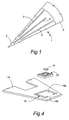
- Figure 4 is a simplified view of a detail of the assembly of
Figure 2, including a micro-electro-mechanical structure,
which implements a first embodiment of the present invention;
- Figure 5 is a schematic top plan view of the micro-electro-mechanical
structure of Figure 4, in which parts have been
removed;
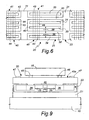
- Figure 6 illustrates an enlarged detail of Figure 5;
- Figures 7 and 8 are cross sections through the micro-electro-mechanical
structure of Figure 4, taken along lines
VII-VII and, respectively, VIII-VIII of Figure 5;
- Figure 9 is a cross section of the micro-electro-mechanical
structure of Figure 4 in use, taken along line IX-IX of Figure
5;
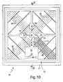
- Figure 10 is a schematic top plan view of a micro-electro-mechanical
structure in a second embodiment of the present
invention; and
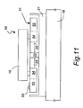
- Figure 11 is a cross section of the micro-electro-mechanical
structure of Figure 10, in use, taken along line XI-XI of
Figure 10.
-
By way of example, reference will be made hereinafter to the
case of microactuators integrated in actuator devices with
dual actuation stage for reading hard disks. This must not,
however, be considered in any way limiting, since the
invention can be advantageously used for making also other
types of devices, based upon micro-electro-mechanical
structures (MEMS structures).
-
Figure 2 schematically illustrates a rotary type actuator
device 10 comprising a motor 12 (also referred to as "voice-coil
motor") fixed to a supporting body 13 generally
designated as E-block on account of its E-like shape in side
view (see Figure 3). The supporting body 13 has a plurality of
arms 14 each carrying a suspension 15 formed by a plate fixed
like a cantilever beam. Each suspension 15 carries, at one of
its ends, i.e., the one that is not fixed to the supporting
body 13, a read/write (R/W) transducer 16 arranged (in the
operative condition) so as to face one surface of a hard disk
17 and to be able to perform movements of roll and pitch for
following the surface of the hard disk 17. For this purpose,
the R/W transducer 16 (also referred to as "slider") is fixed
to a gimbal 18 (also called flexure), formed generally by the
suspension 15 and consisting, for example, of a rectangular
plate 18a, cut out on three and a half sides, from the plate
of the suspension 15 and the portion 18b of which for
connection to the suspension 15 enables flexing of the plate
18a (see Figure 4).
-
In order to increase the density of data storage, the actuator
device 10 is equipped with a dual actuation stage, with a
first coarser actuation stage, constituted by the motor 12,
which displaces the assembly formed by the supporting body 13,
the suspension 15 and the R/W slider 16 through the hard disk
17 during coarse search for the trace, and a second actuation
stage that carries out a finer control of the position of the
slider 16 during tracking. In particular, the second actuation
stage comprises a microactuator 20 set between the gimbal 18
and the R/W transducer 16, as may be seen from Figure 4, which
illustrates, in exploded view, the end of the suspension 15,
the gimbal 18, the slider 16, and the microactuator 20, which
here is of a rotational type.
-
The microactuator 20 is based upon a rotational type micro-electro-mechanical
structure and will be described hereinafter
in detail with reference to Figures 5 to 8, where some parts
have been removed for clarity. The microactuator 20 comprises
a stator 21, provided with a central pin 22, and a rotor 23,
rotatable with respect to the stator 21 about an axis A of
relative rotation, which is also an axis of the pin 22. More
precisely, the rotor 23 oscillates about a relative position
of equilibrium. Both the stator 21 and the rotor 23 are of
semiconductor material, preferably polycrystalline silicon,
and are moreover substantially symmetrical with respect to the
axis A. The rotor 23 is connected to the stator 21 by springs
25 anchored to the pin 22. In greater detail, the springs 25
extend diametrically opposite from the pin 22, in radial
directions with respect to the pin 22, and are connected to
respective anchoring regions 26 of the rotor 23.
-
The rotor 23 is provided with a frame-like supporting
structure 27, which in this case has a substantially square
shape and is connected to the anchoring regions 26 via
supporting arms 28, formed as radial extensions of the
anchoring regions 26. In practice, the supporting arms 28 are
in perpendicular pairs and divide the microactuator 20 into a
first, a second, a third, and a fourth sector 20a-20d,
arranged in diametrically opposite pairs with respect to the
pin 22 and substantially symmetrical about the axis A. In
greater detail, the first sector 20a and the second sector 20b
are diametrically opposite to one another; the third sector
20c and the fourth sector 20d are also diametrically opposite
to one another and are moreover adjacent to the first sector
20a and to the second sector 20b.
-
Each of the sectors 20a-20d of the microactuator 20 comprises
a respective group of rotor electrodes 30, defined by
respective planar semiconductor plates with substantially
parallel faces. The rotor electrodes 30 are arranged according
to respective planes parallel to the axis A. In greater
detail, the rotor electrodes 30 of the first sector 20a and of
the second sector 20b are parallel to a first plane P1, which
includes the axis A, are distributed in both of the opposite
half-spaces defined by the first plane P1, and are
substantially arranged at equal distances apart from one
another. The rotor electrodes 30 of the third sector 20c and
of the fourth sector 20d are parallel to a second plane P2,
which includes the axis A and is substantially orthogonal to
the first plane P1, are distributed in both of the opposite
half-spaces defined by the first plane P2, and are
substantially arranged at equal distances apart from one
another. In practice, therefore, the rotor electrodes 30 of
sectors 20a-20d opposite to the pin 22 are parallel to one
another, whilst the rotor electrodes 30 of sectors 20a-20d
that are adjacent are relatively rotated by an angle of
approximately 90°.
-
In each of the sectors 20a-20d, the rotor electrodes 30 extend
from regions inside the rotor 23 up to the supporting
structure 27 and, preferably, their midpoints are aligned. For
preventing bending of the rotor electrodes 30, in each sector
20a-20d the rotor 23 is provided with a plurality of
reinforcement ribs 31, which extend transverse to the rotor
electrodes 30 and are arranged at respective pre-determined
distances from the axis A (for example, approximately one
quarter, one half and three quarters of the longest rotor
electrode 30).
-
The stator 21 comprises a substrate 32, from which the pin 22
projects cantilevered, and groups of first and second stator
electrodes 33, 34, which are comb-fingered with the rotor
electrodes 30. In Figure 5, the stator electrodes 33, 34 are,
for greater clarity, illustrated with dashed lines. In detail
(see Figures 7 and 8), the pin 22, which is also of
semiconductor material, is electrically insulated from the
substrate 32 by a dielectric layer 35, whereas it is connected
to the rotor 23 through the springs 25, which are conductive.
In addition, an electrical-connection line connected to the
pin 22, of known type and not illustrated here, enables bi-directional
exchange of electrical signals between the rotor
23 and a control unit, which is also known and not
illustrated.
-
The stator electrodes 33, 34 are formed by respective
semiconductor plates with planar and parallel faces, carried
on respective insulating bases 36 (see Figure 8), and, like
the rotor electrodes 30, are arranged according to respective
planes parallel to the axis A. In greater detail, each of the
rotor electrodes 30 is set between a respective first stator
electrode 33 and a respective second stator electrode 34.
Furthermore, each rotor electrode 30 and the first stator
electrode 33 and the second stator electrode 34 adjacent
thereto are substantially parallel and form a first capacitor
38 and, respectively, a second capacitor 39 having plane
parallel plates and variable capacitance (see, in particular,
Figure 6). In particular, the capacitances of the first
capacitors 38 and the second capacitors 39 depend upon the
distance between the rotor electrodes 30 and the respective
adjacent stator electrodes 33, 34, and thus depend upon the
relative angular position of the rotor 23 with respect to the
stator 21. Clearly, the stator electrodes 33, 34 connected to
the rotor electrodes 30 of the first sector 20a and second
sector 20b are parallel to the first plane P1, whereas the
stator electrodes 33, 34 connected to the rotor electrodes 30
of the third sector 20a and of the fourth sector 20b are
parallel to the second plane P2. The stator electrodes 33, 34
moreover have interruptions 37, which house the reinforcement
ribs 31 of the rotor 23.
-
As illustrated in Figures 6 to 8, first connection lines 40
and second connection lines 41 extend on the substrate 32,
transverse to the first stator electrodes 33 and to the second
stator electrodes 34, and are embedded in the insulating bases
36. The first stator electrodes 33 are connected to the
immediately underlying first connection lines 40, through
respective first connection regions 43. Likewise, the second
stator electrodes 34 are connected to the immediately
underlying second connection lines 41, through respective
second connection regions 44.
-
Figure 9 illustrates the microactuator 20 in use, mounted on
the gimbal 18 and on the R/W transducer 16. In particular,
Figure 9 also illustrates a protective cap 45 applied to
provide a covering for the microactuator 20. The protective
cap 45, which is also of semiconductor material, is bonded to
the anchoring regions 26 of the rotor 23 and carries the R/W
transducer 16 on a face 45a opposite to the rotor 23. For
example, the R/W transducer 16 is bonded by a ring 46 of
vitreous bonding material. Moreover, on the face 45a of the
protective cap 45 pads 47 are provided for electrical
connection of the R/W transducer 16.
-
The advantages of the invention emerge clearly from the above
description.
-
First, in the microactuator 20, the rotor electrodes 30 and
the respective adjacent stator electrodes 33, 34 are
substantially parallel both in the relative resting position
of the rotor 23 with respect to the stator 21, and when, in
use, the rotor 23 is located outside said relative resting
position. In fact, the oscillation permitted by the springs 26
that constrain the rotor 23 to the stator 21 is minimal and
does not modify significantly the condition of parallelism.
Consequently, the rotor and stator electrodes are subjected to
electrostatic forces that are uniform throughout their
extension.
-
Second, since all the adjacent rotor and stator electrodes are
parallel, it is possible to achieve a high compactness and to
reduce considerably the overall dimensions of the
microactuator 20. In particular, owing to the uniform spacing
between adjacent electrodes, all the space available is
exploited in an optimal way. Advantageously, therefore, the
microactuator 20 also has a high electrode density, which
enables an increase in the efficiency of electrostatic force-torque
conversion. In the embodiment described, in particular,
the midpoints of the rotor electrodes are aligned and thus the
resultant of the electrostatic forces applied to the rotor
electrodes of a same sector is applied along the midline of
the rotor electrodes themselves. If we designate by C the
torque applied to the rotor 23, by F the resultant of the
electrostatic forces acting upon one of the sectors 23a-23d
and by L the length of the sides of the rotor 23, in each
sector the arm of the resultant F with respect to the axis A
is approximately equal to L 2 /4 and thus the torque C is
approximately FL 2 . In practice, the conversion efficiency of
the microactuator 20 is five to ten times greater than that of
conventional rotational microactuators with a radial
structure. From this point of view, also the use of the
reinforcement ribs 31 is advantageous, since it enables
strengthening of the rotor 23. It is thus also possible to
make rotor electrodes that are very long for exploiting a
larger arm, at the same time preventing the risks due to the
flexure.
-
The microactuator 20 can moreover be fabricated using standard
micromachining processes and techniques.
-
A second embodiment of the invention is illustrated in Figures
10 and 11, in which parts already shown are designated with
the same reference numbers. In a microactuator 50, a rotor 51,
which is rotatable with respect to the stator 21, is provided
with rotor electrodes 52, arranged with respect to the axis A
of relative rotation in the same way as the rotor electrodes
30 of the rotor 23 of Figures 5-9. In this case, the rotor 51
is moreover provided with a contact region 53, which extends
substantially between one of the anchoring regions 26 and the
supporting structure 27.
-
With reference to Figure 11, in use the R/W transducer 16 is
bonded directly on anchoring regions 54 of the rotor 51.
Provided on the contact region 53 of the rotor 51 are pads 55
for electrical connection of the R/W transducer 16 to a
control unit, which is known and is not illustrated here.
-
The microactuator 50 is not encapsulated, but has the
advantage of being simpler and less costly to manufacture,
since it requires fewer fabrication steps. The microactuator
50 is thus particularly suitable for being used in protected
environments, where the presence of dust and impurities is
negligible.
-
Finally, it is clear that modifications and variations may be
made to the micro-electro-mechanical structure described
herein, without thereby departing from the scope of the
present invention.
-
First, the micro-electro-mechanical structure according to the
invention can be advantageously exploited also for making
devices other than microactuators; in particular, it is
possible to fabricate sensors such as, for example, rotational
accelerometers.
-
The rotor and the stator could then have a different
structure. For example, only two sectors arranged opposite to
one another with respect to the axis of relative rotation,
instead of four, may be envisaged. If so required, even just a
single sector may be provided. The rotor and stator electrodes
of each sector may also be arranged all in just one of the
half-spaces defined by a plane containing the axis of relative
rotation between the stator and the rotor. The supporting
structure could be of a different shape, for example circular.