EP1439663B1 - Verfahren für eine Klassifizierung von Netzwerk-Komponenten eines paket-orientierten Netzwerks - Google Patents
Verfahren für eine Klassifizierung von Netzwerk-Komponenten eines paket-orientierten Netzwerks Download PDFInfo
- Publication number
- EP1439663B1 EP1439663B1 EP03104227A EP03104227A EP1439663B1 EP 1439663 B1 EP1439663 B1 EP 1439663B1 EP 03104227 A EP03104227 A EP 03104227A EP 03104227 A EP03104227 A EP 03104227A EP 1439663 B1 EP1439663 B1 EP 1439663B1
- Authority
- EP
- European Patent Office
- Prior art keywords
- network
- component
- management
- network component
- components
- Prior art date
- Legal status (The legal status is an assumption and is not a legal conclusion. Google has not performed a legal analysis and makes no representation as to the accuracy of the status listed.)
- Expired - Fee Related
Links
Images

Classifications
-
- H—ELECTRICITY
- H04—ELECTRIC COMMUNICATION TECHNIQUE
- H04L—TRANSMISSION OF DIGITAL INFORMATION, e.g. TELEGRAPHIC COMMUNICATION
- H04L41/00—Arrangements for maintenance, administration or management of data switching networks, e.g. of packet switching networks
-
- H—ELECTRICITY
- H04—ELECTRIC COMMUNICATION TECHNIQUE
- H04L—TRANSMISSION OF DIGITAL INFORMATION, e.g. TELEGRAPHIC COMMUNICATION
- H04L41/00—Arrangements for maintenance, administration or management of data switching networks, e.g. of packet switching networks
- H04L41/12—Discovery or management of network topologies
Definitions
- the following invention relates to a method of classification from network components starting from a central one Management component - often in the literature as a manager designated.
- the problem here is that both networks different Have properties.
- the telephone networks offer connection-oriented, Real-time capable services.
- the most widely used on the data networks is, becomes a connectionless, packet-oriented Defined service.
- the packages become "hop-by-hop" after the so-called “best effort” principle. That means, that packets from the intermediate stations in the network be independently directed to the next station (hop-by-hop) and "as good as possible” are treated. Thereby may it be overloaded or misconfigured Station to delays or even loss of packages come.
- For real-time connections such as telephone calls or video conferences
- this behavior is undesirable because of it audible or visible in case of loss or delay of parcels Disruptions can come.
- Another approach is the so-called external QoS management.
- This manager decides if additional Real-time traffic with a given quality of service in the IP-oriented Network are still allowed or not.
- Around To be able to make a decision requires two preconditions be fulfilled.
- the manager has to be on the network transporting goods and their characteristics, and he knows must have accurate information about the condition and structure of the IP-oriented network. The first requirement is already fulfilled by the procedure.
- the external manager already knows all traffic in the IP-oriented network - she were registered with him and approved accordingly, or declined.
- IP-oriented networks Establishing external QoS management is exactly what it is Topology and thus the way on which individual packets in the network to be transported.
- the network architecture However, it is designed to make all decisions locally and as autonomous as possible in the individual network components hold true. That's why in IP-oriented networks to find no instance representing the topology of the overall network knows.
- to make local decisions is it necessary for the components in IP-oriented networks To have information as the basis of the decision. This information is local (limited to the immediate environment) Views on the overall topology.
- US Pat. No. 6,377,987 B1 discloses an alternative Method for determining the current physical structure a network in which a determination of the Network structure using a set of network addresses he follows. Starting from this set of network addresses is a group of components that determines the Network are assigned. Subsequently, by the components so-called Layer 2 and Layer 3 configuration information read out about neighborhood relations between determine the components.
- FIG Management architecture The basic structure of a data network will be described with reference to FIG Management architecture illustrates. This architecture consists of the four main components:
- a central management component M takes place an access to the manageable network components G-A, G-B, G-C of the IP-oriented network DN.
- the manageable network components G-A, G-B, G-C are in the management-capable network components G-A, G-B, G-C so-called Management agent units A are provided, respectively a management interface for the manageable Network components G-A, G-B, G-C provide.
- SNMP a management interface for the manageable Network components
- the management agent units A serve further to one Management of one in the manageable network components G-A, G-B, G-C respectively stored management information Base MIB.
- the Management Information Base MIB includes a Plurality of so-called "managed objects" MO.
- a managed Object MO is a variable that defines the state or history a manageable network components G-A, G-B, G-C describes or specifies. What information in a managed Object MO are, among other things, in the standard RFC 1213; McCloghrie, M. Rose: "Management Information Base for Network Management of TCP / IP-bases internets: MIB-II ", March 1991.
- the set of all in a network component G-A, G-B, G-C existing Managed Objects MO forms the management information Base MIB.
- the Management Information Base MIB describes thus the history of a management-capable network component G-A, G-B, G-C, his condition and thus his local view of the IP-oriented network DN.
- the next step in topology discovery is to recognize that To classify network components. This means, into different categories, such as host, router or switch to divide.
- the host is a network component assigned to a user, such as a workstation or a so-called "IP Phone", understood.
- a router are generally network components with Means switching capacity in packet switching networks, where an arrangement of the packages based on the Layer 3 of the OSI reference model.
- Switches are network components with switching capacity in packet switching networks, where an arrangement of the packages based on the Layer 2 of the OSI reference model.
- a subdivision is necessary because of the network components different information for each category are queriable. For example, a router has information to other subnets that do not have a switch or host have.
- the prior art classifies a network component by a query of the corresponding to Classification provided Managed Objects MO in the management Information Base MIB.
- Managed Objects MO in many of the market Products are included in the Management Information Base MIB
- inappropriate or even incorrect values entered. additionally become the Managed Objects MO by an unclear definition of the standard inconsistent from different manufacturers used. For these reasons, it is not possible different network components using the, provided for Contents of the Management Information Base MIB correct to classify.
- the present invention is therefore based on the object to specify a procedure with which to classify correctly network components.
- a first step will be included Determines if a network component is up is a manageable network component, or Not.
- a significant advantage of the method consists in that the process with little effort in already existing systems can be implemented.
- An advantage of embodiments defined in the subclaims is, inter alia, that by a use of standard available information and a combination of properties and the history of a network component a vendor-independent Classify the network component to simple Way is possible.
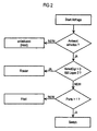
- FIG. 2 For a better illustration of the method according to the invention is in the description of FIG. 2 further to the Designations and reference numbers of Fig. 1 reference.
- the central management component M starting from the central management component M is determined in a first step, whether it is a network component G-A, G-B, G-C is a management-capable network component G-A, G-B, G-C acts. For this, it checks if on the network component G-A, G-B, G-C one of the central management component M assigned management agent unit A implements is, i. whether the network component G-A, G-B, G-C on the Request of the central management component M answers.
- Is not a management agent entity on the network component G-A, G-B, G-C A can be implemented by this network component G-A, G-B, G-C no management information be queried.
- the class of network component G-A, G-B, G-C is thus unknown. In most cases it acts these are hosts.
- a network component G-A, G-B, G-C is received in a second step checks if the network component G-A, G-B, G-C supports layer 3 of the OSI reference model, and whether already data packets between the interfaces the network component G-A, G-B, G-C have been forwarded.
- the layer 3 of OSI reference model is supported by querying the Managed Objects "sysServices" determined. Every router tested reports that layer 3 supports the OSI reference model will, but also some switches, or as such configured routers. To exclude these cases, In addition, the history of the network component G-A, G-B, G-C considered.
- the central management component M is the Managed Object "ipForwDatagrams" queried.
- the managed object "ipForwDatagrams" is defined as a counter, only then is increased when a brokering of data packets based on Layer 3 of the OSI Reference Model.
- a negative test result is determined in the second step, so in a third step in addition the number the ports of the network component G-A, G-B, G-C. This is done by querying the managed object "ifNumber". In cases where the port number is greater than 1, the network component G-A, G-B, G-C as a switch and in the other cases classified as a host.
- the in the central management component M by means of the invention Method determined topology information For example, as part of a resource administration or for acceptance control for real-time critical Network connections are used. Also a use in the Framework of network planning tools is possible.
Description
- die Netwerk-Komponente die Schicht 3 des OSI-Referenzmodells unterstützt, und
- ob bereits Datenpakete zischen den Schnittstellen der Netzwerk-Komponente weitergeleitet wurden,
- Fig. 1:
- ein Strukturbild mit den wesentlichen Funktionseinheiten einer Management Architektur in einem paket-orientierten Netzwerk; und
- Fig. 2:
- ein Ablaufdiagramm zur Veranschaulichung der wesentlichen beim erfindungsgemäßen Verfahren ablaufenden Verfahrensschritte.
Claims (8)
- Verfahren für eine Klassifizierung von Netzwerk-Komponenten (G-A, G-B, G-C) eines paket-orientierten Netzwerks (DN) ausgehend von einer zentralen Management-Komponente (M), bei dem in einem ersten Schritt ermittelt wird, ob es sich bei einer Netzwerk-Komponente (G-A, G-B, G-C) um eine managementfähige Netzwerk-Komponente (G-A, G-B, G-C) handelt, und falls dies der Fall ist, überprüft wird,wobei in Fällen, in denen dies der Fall ist, die Netzwerk-Komponente (G-A, G-B, G-C) als Router klassifiziert wird.ob die Netzwerk-Komponente (G-A, G-B, G-C) die Schicht 3 des OSI-Referenzmodells unterstützt, undob bereits Datenpakete zwischen den Schnittstellen der Netzwerk-Komponente (G-A, G-B, G-C) weitergeleitet wurden,
- Verfahren nach Patentanspruch 1,
dadurch gekennzeichnet, dass für eine Kommunikation zwischen der zentralen Management-Komponente (M) und einer managementfähigen Netzwerk-Komponente (G-A, G-B, G-C) auf dieser eine der zentralen Management-Komponente (M) zugeordnete Management-Agenteneinheit (A) implementiert ist. - Verfahren nach Patentanspruch 2,
dadurch gekennzeichnet, dass eine Kommunikation zwischen der zentralen Management-Komponente (M) und der Management-Agenteneinheit (A) mittels des SNMP-Protokolls (Simple Network Management Protocol) erfolgt. - Verfahren nach einem der vorhergehenden Patentansprüche,
dadurch gekennzeichnet, dass in Fällen, in denen ein negatives Prüfungsergebnis ermittelt wird, die Anzahl der Ports der Netzwerk-Komponente (G-A, G-B, G-C) überprüft wird,
wobei in Fällen, in denen die Portanzahl größer 1 ist, die Netzwerk-Komponente (G-A, G-B, G-C) als Switch und in den anderen Fällen als Host klassifiziert wird. - Verfahren nach Patentanspruch 4,
dadurch gekennzeichnet, dass die Überprüfungen durch eine Abfrage von Managed Objects (MO) in einer Management Information Base (MIB) der entsprechenden Netzwerk-Komponente (G-A, G-B, G-C) erfolgen. - Verfahren nach Patentanspruch 5,
dadurch gekennzeichnet, dass die Management Information Base (MIB) einer Netzwerk-Komponente (G-A, G-B, G-C) durch die in der Netzwerk-Komponente (G-A, G-B, G-C) implementierte Management-Agenteneinheit (A) verwaltet wird. - Zentrale Management-Komponente (M),
dadurch gekennzeichnet, dass die Komponente zur Durchführung eines Verfahrens nach einem der Patentansprüche 1 bis 6 konfiguriert ist. - Programm mit einer Befehlsfolge,
dadurch gekennzeichnet, dass bei einer Ausführung der Befehlsfolge durch einen Prozessor ein Verfahren nach einem der Patentansprüche 1 bis 6 ausgeführt wird.
Applications Claiming Priority (2)
| Application Number | Priority Date | Filing Date | Title |
|---|---|---|---|
| DE10301963A DE10301963A1 (de) | 2003-01-20 | 2003-01-20 | Verfahren für eine Klassifizierung von Netzwerk-Komponenten eines paket-orientierten Netzwerks |
| DE10301963 | 2003-01-20 |
Publications (3)
| Publication Number | Publication Date |
|---|---|
| EP1439663A2 EP1439663A2 (de) | 2004-07-21 |
| EP1439663A3 EP1439663A3 (de) | 2004-09-15 |
| EP1439663B1 true EP1439663B1 (de) | 2005-08-17 |
Family
ID=32520039
Family Applications (1)
| Application Number | Title | Priority Date | Filing Date |
|---|---|---|---|
| EP03104227A Expired - Fee Related EP1439663B1 (de) | 2003-01-20 | 2003-11-17 | Verfahren für eine Klassifizierung von Netzwerk-Komponenten eines paket-orientierten Netzwerks |
Country Status (4)
| Country | Link |
|---|---|
| US (1) | US8467299B2 (de) |
| EP (1) | EP1439663B1 (de) |
| CN (1) | CN1279717C (de) |
| DE (2) | DE10301963A1 (de) |
Families Citing this family (58)
| Publication number | Priority date | Publication date | Assignee | Title |
|---|---|---|---|---|
| US9137115B2 (en) * | 2004-12-06 | 2015-09-15 | Bmc Software, Inc. | System and method for resource reconciliation in an enterprise management system |
| US8683032B2 (en) | 2004-12-06 | 2014-03-25 | Bmc Software, Inc. | Generic discovery for computer networks |
| GB2431067B (en) | 2005-10-07 | 2008-05-07 | Cramer Systems Ltd | Telecommunications service management |
| GB2432992B (en) * | 2005-11-18 | 2008-09-10 | Cramer Systems Ltd | Network planning |
| GB2433675B (en) * | 2005-12-22 | 2008-05-07 | Cramer Systems Ltd | Communications circuit design |
| GB2435362B (en) * | 2006-02-20 | 2008-11-26 | Cramer Systems Ltd | Method of configuring devices in a telecommunications network |
| US8655490B2 (en) | 2008-10-27 | 2014-02-18 | Lennox Industries, Inc. | System and method of use for a user interface dashboard of a heating, ventilation and air conditioning network |
| US8437878B2 (en) | 2008-10-27 | 2013-05-07 | Lennox Industries Inc. | Alarm and diagnostics system and method for a distributed architecture heating, ventilation and air conditioning network |
| US8295981B2 (en) | 2008-10-27 | 2012-10-23 | Lennox Industries Inc. | Device commissioning in a heating, ventilation and air conditioning network |
| US9632490B2 (en) | 2008-10-27 | 2017-04-25 | Lennox Industries Inc. | System and method for zoning a distributed architecture heating, ventilation and air conditioning network |
| US8762666B2 (en) | 2008-10-27 | 2014-06-24 | Lennox Industries, Inc. | Backup and restoration of operation control data in a heating, ventilation and air conditioning network |
| US8452906B2 (en) | 2008-10-27 | 2013-05-28 | Lennox Industries, Inc. | Communication protocol system and method for a distributed-architecture heating, ventilation and air conditioning network |
| US8543243B2 (en) | 2008-10-27 | 2013-09-24 | Lennox Industries, Inc. | System and method of use for a user interface dashboard of a heating, ventilation and air conditioning network |
| US9261888B2 (en) | 2008-10-27 | 2016-02-16 | Lennox Industries Inc. | System and method of use for a user interface dashboard of a heating, ventilation and air conditioning network |
| US9268345B2 (en) | 2008-10-27 | 2016-02-23 | Lennox Industries Inc. | System and method of use for a user interface dashboard of a heating, ventilation and air conditioning network |
| US8694164B2 (en) | 2008-10-27 | 2014-04-08 | Lennox Industries, Inc. | Interactive user guidance interface for a heating, ventilation and air conditioning system |
| US8798796B2 (en) | 2008-10-27 | 2014-08-05 | Lennox Industries Inc. | General control techniques in a heating, ventilation and air conditioning network |
| US8744629B2 (en) | 2008-10-27 | 2014-06-03 | Lennox Industries Inc. | System and method of use for a user interface dashboard of a heating, ventilation and air conditioning network |
| US9152155B2 (en) | 2008-10-27 | 2015-10-06 | Lennox Industries Inc. | Device abstraction system and method for a distributed-architecture heating, ventilation and air conditioning system |
| US8600558B2 (en) | 2008-10-27 | 2013-12-03 | Lennox Industries Inc. | System recovery in a heating, ventilation and air conditioning network |
| US8239066B2 (en) | 2008-10-27 | 2012-08-07 | Lennox Industries Inc. | System and method of use for a user interface dashboard of a heating, ventilation and air conditioning network |
| US8437877B2 (en) | 2008-10-27 | 2013-05-07 | Lennox Industries Inc. | System recovery in a heating, ventilation and air conditioning network |
| US8452456B2 (en) | 2008-10-27 | 2013-05-28 | Lennox Industries Inc. | System and method of use for a user interface dashboard of a heating, ventilation and air conditioning network |
| US8788100B2 (en) | 2008-10-27 | 2014-07-22 | Lennox Industries Inc. | System and method for zoning a distributed-architecture heating, ventilation and air conditioning network |
| US9432208B2 (en) | 2008-10-27 | 2016-08-30 | Lennox Industries Inc. | Device abstraction system and method for a distributed architecture heating, ventilation and air conditioning system |
| US8352080B2 (en) | 2008-10-27 | 2013-01-08 | Lennox Industries Inc. | Communication protocol system and method for a distributed-architecture heating, ventilation and air conditioning network |
| US8892797B2 (en) | 2008-10-27 | 2014-11-18 | Lennox Industries Inc. | Communication protocol system and method for a distributed-architecture heating, ventilation and air conditioning network |
| US8855825B2 (en) | 2008-10-27 | 2014-10-07 | Lennox Industries Inc. | Device abstraction system and method for a distributed-architecture heating, ventilation and air conditioning system |
| US8802981B2 (en) | 2008-10-27 | 2014-08-12 | Lennox Industries Inc. | Flush wall mount thermostat and in-set mounting plate for a heating, ventilation and air conditioning system |
| US8564400B2 (en) | 2008-10-27 | 2013-10-22 | Lennox Industries, Inc. | Communication protocol system and method for a distributed-architecture heating, ventilation and air conditioning network |
| US8433446B2 (en) | 2008-10-27 | 2013-04-30 | Lennox Industries, Inc. | Alarm and diagnostics system and method for a distributed-architecture heating, ventilation and air conditioning network |
| US8463443B2 (en) | 2008-10-27 | 2013-06-11 | Lennox Industries, Inc. | Memory recovery scheme and data structure in a heating, ventilation and air conditioning network |
| US9678486B2 (en) | 2008-10-27 | 2017-06-13 | Lennox Industries Inc. | Device abstraction system and method for a distributed-architecture heating, ventilation and air conditioning system |
| US8463442B2 (en) | 2008-10-27 | 2013-06-11 | Lennox Industries, Inc. | Alarm and diagnostics system and method for a distributed architecture heating, ventilation and air conditioning network |
| US9651925B2 (en) | 2008-10-27 | 2017-05-16 | Lennox Industries Inc. | System and method for zoning a distributed-architecture heating, ventilation and air conditioning network |
| US8655491B2 (en) | 2008-10-27 | 2014-02-18 | Lennox Industries Inc. | Alarm and diagnostics system and method for a distributed architecture heating, ventilation and air conditioning network |
| US8352081B2 (en) | 2008-10-27 | 2013-01-08 | Lennox Industries Inc. | Communication protocol system and method for a distributed-architecture heating, ventilation and air conditioning network |
| US8725298B2 (en) | 2008-10-27 | 2014-05-13 | Lennox Industries, Inc. | Alarm and diagnostics system and method for a distributed architecture heating, ventilation and conditioning network |
| US8600559B2 (en) | 2008-10-27 | 2013-12-03 | Lennox Industries Inc. | Method of controlling equipment in a heating, ventilation and air conditioning network |
| US8442693B2 (en) | 2008-10-27 | 2013-05-14 | Lennox Industries, Inc. | System and method of use for a user interface dashboard of a heating, ventilation and air conditioning network |
| US8548630B2 (en) | 2008-10-27 | 2013-10-01 | Lennox Industries, Inc. | Alarm and diagnostics system and method for a distributed-architecture heating, ventilation and air conditioning network |
| US8977794B2 (en) | 2008-10-27 | 2015-03-10 | Lennox Industries, Inc. | Communication protocol system and method for a distributed-architecture heating, ventilation and air conditioning network |
| US8661165B2 (en) | 2008-10-27 | 2014-02-25 | Lennox Industries, Inc. | Device abstraction system and method for a distributed architecture heating, ventilation and air conditioning system |
| US9325517B2 (en) | 2008-10-27 | 2016-04-26 | Lennox Industries Inc. | Device abstraction system and method for a distributed-architecture heating, ventilation and air conditioning system |
| US8874815B2 (en) | 2008-10-27 | 2014-10-28 | Lennox Industries, Inc. | Communication protocol system and method for a distributed architecture heating, ventilation and air conditioning network |
| US9377768B2 (en) | 2008-10-27 | 2016-06-28 | Lennox Industries Inc. | Memory recovery scheme and data structure in a heating, ventilation and air conditioning network |
| US8994539B2 (en) | 2008-10-27 | 2015-03-31 | Lennox Industries, Inc. | Alarm and diagnostics system and method for a distributed-architecture heating, ventilation and air conditioning network |
| US8774210B2 (en) | 2008-10-27 | 2014-07-08 | Lennox Industries, Inc. | Communication protocol system and method for a distributed-architecture heating, ventilation and air conditioning network |
| US8615326B2 (en) | 2008-10-27 | 2013-12-24 | Lennox Industries Inc. | System and method of use for a user interface dashboard of a heating, ventilation and air conditioning network |
| US8255086B2 (en) | 2008-10-27 | 2012-08-28 | Lennox Industries Inc. | System recovery in a heating, ventilation and air conditioning network |
| US8560125B2 (en) | 2008-10-27 | 2013-10-15 | Lennox Industries | Communication protocol system and method for a distributed-architecture heating, ventilation and air conditioning network |
| US10831724B2 (en) * | 2008-12-19 | 2020-11-10 | Bmc Software, Inc. | Method of reconciling resources in the metadata hierarchy |
| USD648642S1 (en) | 2009-10-21 | 2011-11-15 | Lennox Industries Inc. | Thin cover plate for an electronic system controller |
| USD648641S1 (en) | 2009-10-21 | 2011-11-15 | Lennox Industries Inc. | Thin cover plate for an electronic system controller |
| US8260444B2 (en) | 2010-02-17 | 2012-09-04 | Lennox Industries Inc. | Auxiliary controller of a HVAC system |
| US8712979B2 (en) | 2010-03-26 | 2014-04-29 | Bmc Software, Inc. | Statistical identification of instances during reconciliation process |
| US10127296B2 (en) | 2011-04-07 | 2018-11-13 | Bmc Software, Inc. | Cooperative naming for configuration items in a distributed configuration management database environment |
| US9158799B2 (en) | 2013-03-14 | 2015-10-13 | Bmc Software, Inc. | Storing and retrieving context sensitive data in a management system |
Family Cites Families (6)
| Publication number | Priority date | Publication date | Assignee | Title |
|---|---|---|---|---|
| JP3521955B2 (ja) * | 1994-06-14 | 2004-04-26 | 株式会社日立製作所 | 階層型ネットワーク管理システム |
| JP2871469B2 (ja) | 1994-07-19 | 1999-03-17 | 日本電気株式会社 | Atm網構成管理方法 |
| US6249814B1 (en) * | 1997-09-22 | 2001-06-19 | Compaq Computer Corporation | Method and apparatus for identifying devices on a network |
| US6377987B1 (en) * | 1999-04-30 | 2002-04-23 | Cisco Technology, Inc. | Mechanism for determining actual physical topology of network based on gathered configuration information representing true neighboring devices |
| US7698396B2 (en) * | 2000-01-31 | 2010-04-13 | Hitachi Software Engineering Co., Ltd. | Method of automatically recognizing network configuration including intelligent packet relay equipment, method of displaying network configuration chart, and system thereof |
| US6804712B1 (en) * | 2000-06-30 | 2004-10-12 | Cisco Technology, Inc. | Identifying link failures in a network |
-
2003
- 2003-01-20 DE DE10301963A patent/DE10301963A1/de not_active Withdrawn
- 2003-11-17 EP EP03104227A patent/EP1439663B1/de not_active Expired - Fee Related
- 2003-11-17 DE DE50300995T patent/DE50300995D1/de not_active Expired - Lifetime
- 2003-12-22 CN CNB2003101131083A patent/CN1279717C/zh not_active Expired - Fee Related
-
2004
- 2004-01-20 US US10/759,073 patent/US8467299B2/en not_active Expired - Fee Related
Also Published As
| Publication number | Publication date |
|---|---|
| EP1439663A2 (de) | 2004-07-21 |
| DE10301963A1 (de) | 2004-08-05 |
| CN1279717C (zh) | 2006-10-11 |
| US8467299B2 (en) | 2013-06-18 |
| CN1518280A (zh) | 2004-08-04 |
| EP1439663A3 (de) | 2004-09-15 |
| US20040146008A1 (en) | 2004-07-29 |
| DE50300995D1 (de) | 2005-09-22 |
Similar Documents
| Publication | Publication Date | Title |
|---|---|---|
| EP1439663B1 (de) | Verfahren für eine Klassifizierung von Netzwerk-Komponenten eines paket-orientierten Netzwerks | |
| DE60132387T2 (de) | Richtlinien-Koordination in einem Kommunikationsnetz | |
| DE60212511T2 (de) | System und Verfahren zur Ermittlung von Datenflussqualitätsstatistiken für Echtzeitprotokolldatenflüsse | |
| DE60316745T2 (de) | Erleichterung der beschleunigten Verarbeitung von Nachrichten des Internet Group Management Protokolls | |
| DE60221228T2 (de) | Verfahren und system zur anycast-wegleitung zwischen mehreren wirtsrechnern | |
| DE69933417T2 (de) | Vorrichtung und Verfahren zur routerfreien Schicht 3 Wegelenkung in einem Netz | |
| DE69911445T2 (de) | Verfahren und vorrichtung zur entdeckung von mitteln unter verwendung von mehrfachübertragungsumfang | |
| DE69733498T2 (de) | Verteiltes rechnersystem und verfahren zur aufteilung von benutzeranfragen auf duplizierte netzwerkserver | |
| DE60031776T2 (de) | Verfahren und vorrichtung für ein kommunkationsnetz | |
| DE602005002374T2 (de) | System und Verfahren zur unnumerierten Netzwerkverbindung-Erkennung | |
| DE60123656T2 (de) | System um die steuerung von echtzeit-transport-protokollflüsse über mehrere netzwerke zu unterstützen unter verwendung einer gruppe von sitzungsroutern | |
| DE60112115T2 (de) | Erweiterungen eines signalisierungs-übertragungsprotokolls für lastausgleich undserverpool-unterstützung | |
| DE60204581T2 (de) | Verfahren zur Optimierung der Verteilung eines Dienstes von einer Quelle zu mehreren Dienstempfängern in einem Netzwerk | |
| DE102011017299A1 (de) | Phasenbasierte Priorisierung von IMS-Signalisierungsnachrichten für eine Überlastdrosselung | |
| DE69631888T2 (de) | Kommunikationssystem und dienststeuerung für anrufbearbeitung | |
| EP1397009A1 (de) | Verfahren und Vorrichtung zur Nachrichtenlenkung in SS7-Netzen | |
| DE60038171T2 (de) | Verfahren zur Auswahl von Übertragungsentitäten | |
| EP1317820B1 (de) | Verfahren zum aufbau von verbindungen mit vorgegebener dienstgüte für ein paketorientiertes kommunikationsnetz mit einem resourcenmanager | |
| DE60030273T2 (de) | Verfahren und systeme zur lenkung von zeichengabenachrichten in einem kommunikationsnetz unter verwendung von sprechkreisadress (cic)-information | |
| DE60313026T2 (de) | Verfahren und gerät zur verteilung von datenpaketen von einem computer zu einem clustersystem | |
| DE112015007093B4 (de) | Kommunikationsvorrichtung und kommunikationsverfahren | |
| DE102004001656A1 (de) | Verfahren und Vorrichtung für eine adaptive Erfassung von Voice-Over-Paket-Daten (VOP-Daten) | |
| DE69921776T2 (de) | Mobiles IP mit Dienstqualität für fremdes Netz mit fremdem Agent und mehreren mobilen Knoten | |
| DE3620407C2 (de) | ||
| EP1535477B1 (de) | Verfahren zum weiterleiten von signalisierungsnachrichten und zugehörige komponenten |
Legal Events
| Date | Code | Title | Description |
|---|---|---|---|
| PUAI | Public reference made under article 153(3) epc to a published international application that has entered the european phase |
Free format text: ORIGINAL CODE: 0009012 |
|
| AK | Designated contracting states |
Kind code of ref document: A2 Designated state(s): AT BE BG CH CY CZ DE DK EE ES FI FR GB GR HU IE IT LI LU MC NL PT RO SE SI SK TR |
|
| AX | Request for extension of the european patent |
Extension state: AL LT LV MK |
|
| PUAL | Search report despatched |
Free format text: ORIGINAL CODE: 0009013 |
|
| AK | Designated contracting states |
Kind code of ref document: A3 Designated state(s): AT BE BG CH CY CZ DE DK EE ES FI FR GB GR HU IE IT LI LU MC NL PT RO SE SI SK TR |
|
| AX | Request for extension of the european patent |
Extension state: AL LT LV MK |
|
| 17P | Request for examination filed |
Effective date: 20040819 |
|
| 17Q | First examination report despatched |
Effective date: 20041020 |
|
| GRAP | Despatch of communication of intention to grant a patent |
Free format text: ORIGINAL CODE: EPIDOSNIGR1 |
|
| AKX | Designation fees paid |
Designated state(s): DE FR GB IT |
|
| GRAS | Grant fee paid |
Free format text: ORIGINAL CODE: EPIDOSNIGR3 |
|
| GRAA | (expected) grant |
Free format text: ORIGINAL CODE: 0009210 |
|
| AK | Designated contracting states |
Kind code of ref document: B1 Designated state(s): DE FR GB IT |
|
| REG | Reference to a national code |
Ref country code: GB Ref legal event code: FG4D Free format text: NOT ENGLISH |
|
| GBT | Gb: translation of ep patent filed (gb section 77(6)(a)/1977) |
Effective date: 20050818 |
|
| REF | Corresponds to: |
Ref document number: 50300995 Country of ref document: DE Date of ref document: 20050922 Kind code of ref document: P |
|
| ET | Fr: translation filed | ||
| PLBE | No opposition filed within time limit |
Free format text: ORIGINAL CODE: 0009261 |
|
| STAA | Information on the status of an ep patent application or granted ep patent |
Free format text: STATUS: NO OPPOSITION FILED WITHIN TIME LIMIT |
|
| 26N | No opposition filed |
Effective date: 20060518 |
|
| REG | Reference to a national code |
Ref country code: GB Ref legal event code: 732E Free format text: REGISTERED BETWEEN 20121025 AND 20121031 |
|
| REG | Reference to a national code |
Ref country code: FR Ref legal event code: TP Owner name: SIEMENS ENTERPRISE COMMUNICATIONS GMBH & CO. K, DE Effective date: 20130108 |
|
| REG | Reference to a national code |
Ref country code: DE Ref legal event code: R082 Ref document number: 50300995 Country of ref document: DE Representative=s name: FRITZSCHE PATENT, DE |
|
| REG | Reference to a national code |
Ref country code: DE Ref legal event code: R081 Ref document number: 50300995 Country of ref document: DE Owner name: SIEMENS ENTERPRISE COMMUNICATIONS GMBH & CO. K, DE Free format text: FORMER OWNER: SIEMENS AKTIENGESELLSCHAFT, 80333 MUENCHEN, DE Effective date: 20130313 Ref country code: DE Ref legal event code: R082 Ref document number: 50300995 Country of ref document: DE Representative=s name: FRITZSCHE PATENT, DE Effective date: 20130313 Ref country code: DE Ref legal event code: R081 Ref document number: 50300995 Country of ref document: DE Owner name: UNIFY GMBH & CO. KG, DE Free format text: FORMER OWNER: SIEMENS AKTIENGESELLSCHAFT, 80333 MUENCHEN, DE Effective date: 20130313 Ref country code: DE Ref legal event code: R082 Ref document number: 50300995 Country of ref document: DE Representative=s name: FRITZSCHE PATENTANWAELTE, DE Effective date: 20130313 |
|
| REG | Reference to a national code |
Ref country code: DE Ref legal event code: R082 Ref document number: 50300995 Country of ref document: DE Representative=s name: FRITZSCHE PATENT, DE |
|
| REG | Reference to a national code |
Ref country code: DE Ref legal event code: R081 Ref document number: 50300995 Country of ref document: DE Owner name: UNIFY GMBH & CO. KG, DE Free format text: FORMER OWNER: SIEMENS ENTERPRISE COMMUNICATIONS GMBH & CO. KG, 81379 MUENCHEN, DE Effective date: 20131112 Ref country code: DE Ref legal event code: R082 Ref document number: 50300995 Country of ref document: DE Representative=s name: FRITZSCHE PATENT, DE Effective date: 20131112 Ref country code: DE Ref legal event code: R082 Ref document number: 50300995 Country of ref document: DE Representative=s name: FRITZSCHE PATENTANWAELTE, DE Effective date: 20131112 |
|
| REG | Reference to a national code |
Ref country code: FR Ref legal event code: CD Owner name: UNIFY GMBH & CO.KG, DE Effective date: 20140429 |
|
| REG | Reference to a national code |
Ref country code: FR Ref legal event code: PLFP Year of fee payment: 13 |
|
| PGFP | Annual fee paid to national office [announced via postgrant information from national office to epo] |
Ref country code: IT Payment date: 20151124 Year of fee payment: 13 |
|
| REG | Reference to a national code |
Ref country code: DE Ref legal event code: R082 Ref document number: 50300995 Country of ref document: DE Representative=s name: FRITZSCHE PATENTANWAELTE, DE Ref country code: DE Ref legal event code: R081 Ref document number: 50300995 Country of ref document: DE Owner name: UNIFY GMBH & CO. KG, DE Free format text: FORMER OWNER: UNIFY GMBH & CO. KG, 81379 MUENCHEN, DE |
|
| REG | Reference to a national code |
Ref country code: FR Ref legal event code: PLFP Year of fee payment: 14 |
|
| PG25 | Lapsed in a contracting state [announced via postgrant information from national office to epo] |
Ref country code: IT Free format text: LAPSE BECAUSE OF NON-PAYMENT OF DUE FEES Effective date: 20161117 |
|
| REG | Reference to a national code |
Ref country code: FR Ref legal event code: PLFP Year of fee payment: 15 |
|
| PGFP | Annual fee paid to national office [announced via postgrant information from national office to epo] |
Ref country code: DE Payment date: 20171124 Year of fee payment: 15 Ref country code: FR Payment date: 20171124 Year of fee payment: 15 |
|
| PGFP | Annual fee paid to national office [announced via postgrant information from national office to epo] |
Ref country code: GB Payment date: 20171124 Year of fee payment: 15 |
|
| REG | Reference to a national code |
Ref country code: DE Ref legal event code: R119 Ref document number: 50300995 Country of ref document: DE |
|
| GBPC | Gb: european patent ceased through non-payment of renewal fee |
Effective date: 20181117 |
|
| PG25 | Lapsed in a contracting state [announced via postgrant information from national office to epo] |
Ref country code: FR Free format text: LAPSE BECAUSE OF NON-PAYMENT OF DUE FEES Effective date: 20181130 Ref country code: DE Free format text: LAPSE BECAUSE OF NON-PAYMENT OF DUE FEES Effective date: 20190601 |
|
| PG25 | Lapsed in a contracting state [announced via postgrant information from national office to epo] |
Ref country code: GB Free format text: LAPSE BECAUSE OF NON-PAYMENT OF DUE FEES Effective date: 20181117 |