EP1435683A2 - Electronic device with battery charging unit - Google Patents
Electronic device with battery charging unit Download PDFInfo
- Publication number
- EP1435683A2 EP1435683A2 EP03257656A EP03257656A EP1435683A2 EP 1435683 A2 EP1435683 A2 EP 1435683A2 EP 03257656 A EP03257656 A EP 03257656A EP 03257656 A EP03257656 A EP 03257656A EP 1435683 A2 EP1435683 A2 EP 1435683A2
- Authority
- EP
- European Patent Office
- Prior art keywords
- current
- battery
- recharging
- rechargeable battery
- consuming
- Prior art date
- Legal status (The legal status is an assumption and is not a legal conclusion. Google has not performed a legal analysis and makes no representation as to the accuracy of the status listed.)
- Withdrawn
Links
Images


Classifications
-
- H—ELECTRICITY
- H02—GENERATION; CONVERSION OR DISTRIBUTION OF ELECTRIC POWER
- H02J—CIRCUIT ARRANGEMENTS OR SYSTEMS FOR SUPPLYING OR DISTRIBUTING ELECTRIC POWER; SYSTEMS FOR STORING ELECTRIC ENERGY
- H02J7/00—Circuit arrangements for charging or depolarising batteries or for supplying loads from batteries
- H02J7/02—Circuit arrangements for charging or depolarising batteries or for supplying loads from batteries for charging batteries from ac mains by converters
- H02J7/04—Regulation of charging current or voltage
-
- H—ELECTRICITY
- H02—GENERATION; CONVERSION OR DISTRIBUTION OF ELECTRIC POWER
- H02J—CIRCUIT ARRANGEMENTS OR SYSTEMS FOR SUPPLYING OR DISTRIBUTING ELECTRIC POWER; SYSTEMS FOR STORING ELECTRIC ENERGY
- H02J7/00—Circuit arrangements for charging or depolarising batteries or for supplying loads from batteries
- H02J7/0068—Battery or charger load switching, e.g. concurrent charging and load supply
-
- H—ELECTRICITY
- H02—GENERATION; CONVERSION OR DISTRIBUTION OF ELECTRIC POWER
- H02J—CIRCUIT ARRANGEMENTS OR SYSTEMS FOR SUPPLYING OR DISTRIBUTING ELECTRIC POWER; SYSTEMS FOR STORING ELECTRIC ENERGY
- H02J7/00—Circuit arrangements for charging or depolarising batteries or for supplying loads from batteries
- H02J7/0047—Circuit arrangements for charging or depolarising batteries or for supplying loads from batteries with monitoring or indicating devices or circuits
- H02J7/0048—Detection of remaining charge capacity or state of charge [SOC]
- H02J7/0049—Detection of fully charged condition
Landscapes
- Engineering & Computer Science (AREA)
- Power Engineering (AREA)
- Charge And Discharge Circuits For Batteries Or The Like (AREA)
- Secondary Cells (AREA)
Abstract
Description
- The present invention relates to battery-powered electronic device including a DC power input, battery coupling means for coupling the device to a rechargeable battery for charging thereof and the supply of power therefrom and a battery charging circuit for providing current from said input to said coupling means for charging a battery coupled to the device thereby.
- Rechargeable batteries are widely used in portable electronic devices such as, for example, PDAs.
- However, there is a problem in that the recharging needs to be started automatically when the device is provided with power from an external source. In addition, there is another problem in that an expensive integrated circuit (IC) is required to separately control battery recharging, and this increases production costs.
- There is still another problem in the display means of conventional portable electronic devices. The conventional devices have such simple display means for displaying the battery charge state that the various states of the device cannot be displayed to a user as they occur during recharging and discharging of the battery.
- A battery-powered electronic device according to the present invention is characterised by a current sensor for sensing the current demand of the device, excluding current required for battery charging, and the battery charging circuit being responsive to the output of the sensor to control the battery charging current in dependence thereon.
- Preferably, the battery charging circuit includes a charging current feedback control loop.
- Preferably, the battery charging circuit comprises a pulse width modulator for producing a PWM signal in dependence on the output of the current sensor and an integrator for integrating the PWM signal from the pulse width modulator, and the output of the integrator provides the set point for said control loop. S
- Preferably, the pulse width modulator is a microprocessor.
- Preferably, the microprocessor is responsive to the voltage across battery positive and negative terminals of the coupling means to control battery charging according to a trickle charge method or an non-trickle charge method.
- Other preferred and optional features are set forth in claims 6 to 39 appended hereto.
- An embodiment of the present invention will now be described, by way of example, with reference to the accompanying drawings, in which:
- Figure 1 is a block diagram of a digital device having battery charging means according to the present invention;
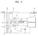
- Figure 2 is a circuit diagram showing in detail the digital device of Figure 1;
- Figure 3 is a flowchart illustrating a method of controlling a pulse width modulator by the microprocessor of Figure 2;
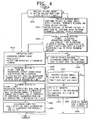
- Figure 4 is a flowchart illustrating a method of recharging the battery in the digital device; and
- Figure 5 is a graph showing the change of the duty cycle of a PWM signal in the microprocessor according to the variations in the current demand.
-
- Referring to Figure 1, a battery charging unit 100 comprises a current
demand detection unit 10, acontrol unit 20, acharging control unit 30, a chargingcurrent detection unit 40 and theloads 50. The term "loads" is used to refer to the other circuits of the device, e.g. a processor and a display device, which draw current during operation of the device. - The current
demand detection unit 10 detects the current flowing into the device from an external source, e.g. a mains adapter (not shown). - The charging
current detection unit 40 detects the battery charging current as the battery is recharged. - The
charging control unit 30 regulates the current fed to the rechargeable battery 60 (Figure 2) in dependence on a pulse width modulation (PWM) control signal output from thecontrol unit 20 and the battery charging current detected by the chargingcurrent detection unit 40. - The
control unit 20 outputs the PWM control signal to thecharging control unit 30. The PWM control signal has a duty cycle which is adjusted according to the current detected by the currentdemand detection unit 10. - In Figure 2, the functional blocks shown in Figure 1 are outlined by dashed lines.
- Referring to Figure 2, the current
demand detection unit 10 comprises a first current sensing resistor R1 in series with theloads 50 and a firstoperational amplifier 12 for amplifying the voltage across the first current sensing resistor R1. The non-inverting (+) and inverting (-) inputs of the firstoperational amplifier 12 are connected to respective ends of the current sensing resistor R1. - The charging
current detection unit 40 includes a second current sensing resistor R2, connected between thebattery 60 and ground, for sensing the battery charging current and a secondoperational amplifier 42 for amplifying the voltage across the second current sensing resistor R2. The non-inverting input of the secondoperational amplifier 42 is connection to a point between the second current sensing resistor R2 and the negative terminal of thebattery 60. The inverting input of thesecond operation amplifier 42 is connection to ground by another resistor R3. - The
charging control unit 30 comprises anintegrator 32 for smoothing the PWM control signal, aswitching control portion 34 for outputting a switching control signal by comparing the output signal from theintegrator 32 with the battery charging current, and aswitching portion 36 for controlling the charging current according to the switching control signal output from theswitching control portion 34. Theswitching control portion 34 comprises a thirdoperational amplifier 34 for amplifying signals, in which the non-inverting input is connected to the converted DC signal of the PWM control signal, output by theintegrator 32, and the inverting input is connected to output of the secondoperational amplifier 42. Theswitching portion 36 comprises a bipolar transistor (TR). The base of the transistor TR is connected to the output of the secondoperational amplifier 34 via a resistor R4. - The battery charging unit 100 further includes a display means 70, e.g. an LED, for displaying the state of the
battery 60. Other display devices, well known to those skilled in the art, could also be used for the display means 70. - The
microprocessor 20 controls the overall operation of the battery charging unit 100 and, specifically, themicroprocessor 20 outputs the PWM control signal to theintegrator 32 so as to control the charging of thebattery 60 according to the device's current demand, and operates theLED 70 according to the charged state of thebattery 60. - Referring to Figure 3, when DC power is supplied from an external source (S310), the
microprocessor 20 first detects the current demand of the device by means of the output signal of the first operational amplifier 12 (S320). Themicroprocessor 20 outputs the PWM control signal to thecharging control unit 30 in accordance with the device's current demand so that a charging current is supplied to the battery 60 (S330). Theintegrator 32 smoothes the PWM control signal and outputs a DC signal to the thirdoperational amplifier 34. The output of the thirdoperational amplifier 34 controls the transistor TR via the resistor R4 and then the transistor TR controls the supply of current from the external source to thebattery 60 according to the DC signal output by the thirdoperational amplifier 34. The transistor TR is turned on according to the magnitude of the initial current demand. As the device's current demand increases and decreases (step S340), themicroprocessor 20 outputs (continuously) the PWM signal with a varying duty cycle according to the increases and decreases in the detected current demand (S350). - Figure 5 shows the change of the PWM signal duty cycle output from the
microprocessor 20 as the device's current demand increases and decreases. When themicroprocessor 20 transmits the PWM control signal with a changed duty cycle, the transistor TR controls the current to thebattery 60, by an amount adjusted in proportion to the changed duty cycle of the PWM control signal. - Therefore, as current is supplied to the
battery 60, battery charging is performed. Concurrently, themicroprocessor 20 detects the battery charging current while thebattery 60 is being charged, using the second current sensing resistor R2 and the third operational amplifier 42 (S340). The output of the thirdoperational amplifier 34 is used for controlling the transistor TR, along with the DC signal which is output from theintegrator 32. Themicroprocessor 20 is able to recognize the battery charge state from the sensed battery charging current. Accordingly, when the detected battery charging current reaches a predetermined current level ("Yes" path from decision step S360), themicroprocessor 20 indicates, using the LED 70 (S370). that battery charging complete. If, however, the charging current does not equal the set up current, the method returns to continuously detecting the current demand and battery charging current step in step S340 ("No" path from decision step S360). - Referring to Figure 4, if the voltage of the
battery 60 is more than 5V ("Yes" path from decision step S410), themicroprocessor 20 determines that thebattery 60 is partially discharged and performs the charging operation according to the state of the digital device being used. To perform the charging operation according to the state of the digital device, themicroprocessor 20 determines its current demand and outputs a PWM control signal according to the current demand (S420). Next, current is fed to thebattery 60, in accordance with the PWM control signal, for charging the battery 60 (S430). Note that step S430 comprises steps S432, S434 and S436. After outputting the PWM control signal in step S420, themicroprocessor 20 determines whether the battery charging current is between 1000 mA and 300 mA inclusive in decision step S432. If it is themicroprocessor 20 flashes theLED 70 one time. - If the charging current reaches 0.3A within 12 hours, which is a predetermined maximum recharge time, the
microprocessor 20 switches to a second charge mode ("Yes" path from decision step S432) in step S434. In step S434 theLED 70 is illuminated continuously and after one hour of recharging thebattery 60, a "charging complete" message is displayed (S436). When charging is completed, theLED 70 is illuminated continuously. In the event that the charging current does not reach 0.3A within 12 hours ("No" path from decision step S432), the battery voltage is checked by the microprocessor 20 (S442). If the battery voltage is more than 7.0V ("Yes" path from decision step S442), theLED 70 is continuously illuminated, and charging is completed after half an hour of recharging (S444). However, if the battery voltage is not more than 7.0V ("No" path from decision step S442), an error message is displayed and the recharging operation is terminated (S480). - Referring back to decision step S410, if the battery voltage is less than or equal to 5V, the
microprocessor 20 controls the charging in a trickle charge mode (S450). In the trickle charge mode, themicroprocessor 20 supplies 80 mA to thebattery 60 for half an hour regardless of the operation of the digital device. If the battery voltage is more than 5V after 2 seconds of the trickle charging, a quick charge is performed. Otherwise, the trickle charging is continued. When the trickle charging begins (decision step S460), themicroprocessor 20 flashes theLED 70. If after one half hour of trickle charging, the battery voltage is more than 5V step S420 is performed by the microprocessor 20 ("Yes" path from decision step S460). If the battery voltage is less than or equal to 5V after one half hour of trickle charging, the method proceeds to decision step S470. In decision step S470, it is determined whether the charging current is not more than 30 mA for two seconds during the trickle charging. If the recharging current is not more than 30 mA for 2 seconds ("Yes" path from decision step S470), an error message is displayed and the recharging operation is terminated (S480). If, however, during trickle charging the recharging current is more than 30 mA, or, it is less than 30 mA, but also for less than 2 seconds, the method continues to recheck the trickle charging current magnitude and duration in decision step S470. - The method discussed above for battery charging of the digital device divides the battery charging into two modes according to the battery's residual capacity. These modes are an operation mode and a trickle mode. If the battery residual capacity is greater than a specific criterion, the operation of the digital device and the charging thereof are performed simultaneously. Otherwise, the
battery 60 is first charged to exceed the criterion and then the operation of the digital device and charging thereof are performed simultaneously. - The may be different numbers of
LEDs 70, different number of times that the or each LED is energised or flashes and different set up times. Therefore, a plurality of theLEDs 70 can be applied for displaying the recharging state of thebattery 60, and it is possible to apply a different number of times of flickering theLED 70, as well as a different setup time. In addition various states can be displayed through theLED 70, such as errors occurring during the battery recharging caused by overcurrent, overvoltage, battery defective, and suspension of charging. - The battery charging unit 100 can operate and charge the
battery 60 simultaneously with the power supplied from the adapter. Embodiments of the present invention can reduce the material costs as well as the number of parts, since the control unit controls the recharging operation instead of the high-priced IC. - In addition, since the
control unit 20 controls the recharging operation, errors such as overcurrent, overvoltage, battery-defective, suspension, as well as completion of recharging, are freely displayed on the display means. Therefore, users can recognize the recharging state of thebattery 60 easily and conveniently.
Claims (39)
- A battery-powered electronic device including a DC power input (DC INPUT), battery coupling means for coupling the device to a rechargeable battery (60) for charging thereof and the supply of power therefrom, and a battery charging circuit (20, 30, 40) for providing current from said input to said coupling means for charging a battery (60) coupled to the device thereby, characterised by a current sensor (10) for sensing the current demand of the device, excluding current required for battery charging, and the battery charging circuit (20, 30, 40) being responsive to the output of the sensor (10) to control the battery charging current in dependence thereon.
- A device according to claim 1, wherein the battery charging circuit (20, 30, 40) includes a charging current feedback control loop (34, R4, 36, 40).
- A device according to claim 2, wherein the battery charging circuit (20, 30, 40) comprises a pulse width modulator (20) for producing a PWM signal in dependence on the output of the current sensor (10) and an integrator (32) for integrating the PWM signal from the pulse width modulator (20), and the output of the integrator (32) provides the set point for said control loop (34, R4, 36, 40).
- A device according to claim 3, wherein the pulse width modulator is a microprocessor (20).
- A device according to claim 4, wherein the microprocessor (20) is responsive to the voltage across battery positive and negative terminals of the coupling means to control battery charging according to a trickle charge method or an non-trickle charge method.
- A digital device capable of recharging a rechargeable battery comprising;
a consuming current detect unit for detecting a consuming current input to the digital device;
a control unit;
a recharging current detect unit for detecting the battery recharging current as the battery is recharged; and
a recharging control unit for regulating the consuming current to the rechargeable battery in proportion to a control signal output from the control unit and the battery recharging current detected by the recharging current detect control unit. - The digital device capable of recharging a rechargeable battery according to claim 6, wherein the control signal includes a pulse width modulation signal.
- The digital device capable of recharging a rechargeable battery according to claim 7, wherein the pulse width module control signal has a duty ratio adjusted according to the consuming current detected by the consuming current detect unit.
- The digital device capable of recharging a rechargeable battery according to claim 6, wherein the consuming current detect unit comprises:a first current detecting resistor for detecting the consuming current; anda first operational amplifier, wherein a first end of the first current detecting resistor is coupled to an inverting input of the first operational amplifier and the second end of the first current detecting resistor is coupled to the non-inverting input of the first operational amplifier.
- The digital device capable of recharging a rechargeable battery according to claim 6, wherein the recharging current detect unit comprises:a second current detecting resistor;a third current detecting resistor for detecting the rechargeable battery recharging current; anda second operational amplifier, wherein a first end of the second current detecting resistor is coupled to a non-inverting input of the second operational amplifier and to the negative terminal of the rechargeable battery, and a first end of the third current detecting resistor is coupled to an inverting input of the third operational amplifier, and further wherein the second end of the second and third current detecting resistors are coupled together to earth ground.
- The digital device capable of recharging a rechargeable battery according to claim 1, wherein the recharging control unit comprises:an integrator, an input of which is coupled to a first output of the control unit;a third operational amplifier;a fourth current detecting resistor; anda transistor, wherein a first output of the integrator is coupled to a non-inverting input of the third operational amplifier, an inverting input of the third operational amplifier is coupled to an output of the recharging current detect unit, a first end of the fourth current detecting resistor is coupled to an output of the third operational amplifier and a second end of the fourth current detecting resistor is coupled to a first input of the transistor, a second input of the transistor is coupled to a power source, and an output of the transistor is coupled to a positive terminal of the rechargeable battery.
- The digital device capable of recharging a rechargeable battery according to claim 6, wherein the control unit includes a microprocessor.
- A method for controlling a digital device to recharge current of a rechargeable battery comprising:detecting a consuming current input to the digital device;detecting a battery recharging current as the battery is recharged; and regulating the consuming current to the rechargeable battery in proportion to a control signal and the detected battery recharging current.
- The method for controlling recharging current of a rechargeable battery according to claim 13, wherein control signal is a pulse width modulation signal.
- The method for controlling recharging current of a rechargeable battery according to claim 13 further comprising:adjusting the control signal according to the detected consuming current.
- The method for controlling recharging current of a rechargeable battery according to claim 13, further comprising:displaying a recharging complete message if the recharging current equals a predetermined value.
- The method for controlling recharging current of a rechargeable battery according to claim 15, wherein the step of adjusting the control signal according to the detected consuming current comprises:determining whether the magnitude of the consuming current increases or decreases; andvarying the pulse width modulation signal duty cycle in accordance with the increase or decrease of the magnitude of the consuming current.
- The method for controlling recharging current of a rechargeable battery according to claim 13, further comprising:outputting a control signal according to a magnitude of the consuming current.
- The method for controlling recharging current of a rechargeable battery according to claim 13, wherein the step of outputting a control signal according to a magnitude of the consuming current comprises:maintaining the pulse width modulation duty cycle substantially at a first constant for a first range of consuming current values;maintaining the pulse width modulation duty cycle substantially at a second constant for a second range of consuming current values; andvarying the pulse width modulation duty cycle linearly from about the first constant to about the second constant, for a third range of consuming current values.
- The method for controlling recharging current of a rechargeable battery according to claim 18, wherein the first constant is in the range of about 50 to about 60 percent duty cycle.
- The method for controlling recharging current of a rechargeable battery according to claim 18, wherein the second constant is in the range of about 20 to about 30 percent duty cycle.
- The method for controlling recharging current of a rechargeable battery according to claim 18, wherein the first range of consuming current values is in the range of at or about 0 milliamps to at or about 275 milliamps.
- The method for controlling recharging current of a rechargeable battery according to claim 18, wherein the second range of consuming current values is in the range of about 950 milliamps to about 1200 milliamps.
- The method for controlling recharging current of a rechargeable battery according to claim 18, wherein the third range of consuming current values is in the range of about 275 milliamps to about 950 milliamps.
- A method for recharging a rechargeable battery in a digital device comprising:determining whether the battery voltage is greater than 5 volts, and if so, determining that the battery is partially discharged and performing a recharge operation according to the state of the digital device being used.
- The method according to claim 25 wherein the step of performing a recharge operation according to the state of the digital device being used comprises;
determining the consuming current;
outputting a control signal according to the consuming current; and
supplying a portion of the consuming current according to the pulse width modulation control signal to the rechargeable battery for recharging. - The method according to claim 26 wherein the control signal includes a pulse width modulation signal.
- The method according to claim 27 wherein the step of supplying a portion of the consuming current according to the pulse width modulation control signal to the rechargeable battery comprises;
determining whether the battery recharging current is between approximately 1000 and 300 milliamps, and if so, illuminating an illumination device at least one time; and
determining if the recharging current reaches 300 milliamps within 12 hours, and if so, switching to a second recharge mode. - The method according to claim 27 wherein the step of switching to a second recharge mode comprises:charging the rechargeable battery for substantially one hour at a recharging current of less than or equal to 300 milliamps and illuminating the illumination device for substantially one hour; andilluminating the illumination device continuously after the first time period has elapsed.
- The method according to claim 26, further comprising:determining that the rechargeable current does not reach 300 milliamps within 12 hours, and checking the battery voltage; anddetermining whether the battery voltage is greater than 7 volts, and if so, illuminating an illumination device continuously.
- The method according to claim 30, further comprising:determining that the battery voltage is less than or equal to 7 volts; anddisplaying an error message and terminating the recharge.
- The method according to claim 25, further comprising:determining that the battery voltage is less than or equal to 5 volts; andcharging the battery for approximately 2 seconds at about 80 milliamps; anddetermining whether the battery voltage is more than 5 volts, and if so, performing a quick recharge, otherwise performing a trickle recharge.
- The method according to claim 32, wherein performing the trickle recharge comprises:supplying approximately 80 milliamps to the battery for approximately one-half hour and illuminating the illumination device momentarily; anddetermining whether the battery voltage is greater than approximately 5 volts approximately one half hour after of recharging, and if so, performing a recharge operation according to the state of the digital device being used.
- The method according to claim 33 wherein the step of performing a recharge operation according to the state of the digital device being used comprises;
determining the consuming current;
outputting a pulse width modulation control signal according to a magnitude of the consuming current; and
supplying a portion of the consuming current according to the pulse width modulation control signal to the rechargeable battery for recharging. - The method according to claim 34 wherein the step of supplying a portion of the consuming current according to the pulse width modulation control signal to the rechargeable battery comprises;
determining whether the battery recharging current is between approximately 1000 and 300 milliamps, and if so, illuminating an illumination device at least one time; and
determining if the recharging current reaches 300 milliamps within 12 hours, and if so, switching to a second recharge mode. - The method according to claim 35 wherein the step of switching to a second recharge mode comprises:charging the rechargeable battery for substantially one hour at a recharging current of less than or equal to 300 milliamps and illuminating the illumination device for substantially one hour; andilluminating the illumination device continuously after the first time period has elapsed.
- The method according to claim 33, further comprising:determining that the rechargeable current does not reach 300 milliamps within 12 hours, and checking the battery voltage; anddetermining whether the battery voltage is greater than 7 volts, and if so, illuminating an illumination device continuously.
- The method according to claim 37, further comprising:determining that the battery voltage is less than or equal to 7 volts; anddisplaying an error message and terminating the recharge.
- The method according to claim 32, further comprising:determining that the battery voltage is less than or equal to approximately 5 volts within approximately one half hour; anddetermining whether the recharge current is not more than approximately 30 milliamps for approximately 2 seconds, and if not, continuing to recheck the magnitude and duration of the trickle recharge and if so, displaying an error message and terminating the recharge.
Applications Claiming Priority (2)
| Application Number | Priority Date | Filing Date | Title |
|---|---|---|---|
| KR2003000112 | 2003-01-02 | ||
| KR10-2003-0000112A KR100481505B1 (en) | 2003-01-02 | 2003-01-02 | Digital device capable of battery charging and method thereof |
Publications (2)
| Publication Number | Publication Date |
|---|---|
| EP1435683A2 true EP1435683A2 (en) | 2004-07-07 |
| EP1435683A3 EP1435683A3 (en) | 2006-03-15 |
Family
ID=32501472
Family Applications (1)
| Application Number | Title | Priority Date | Filing Date |
|---|---|---|---|
| EP03257656A Withdrawn EP1435683A3 (en) | 2003-01-02 | 2003-12-05 | Electronic device with battery charging unit |
Country Status (4)
| Country | Link |
|---|---|
| US (1) | US7411372B2 (en) |
| EP (1) | EP1435683A3 (en) |
| KR (1) | KR100481505B1 (en) |
| CN (2) | CN100477443C (en) |
Cited By (1)
| Publication number | Priority date | Publication date | Assignee | Title |
|---|---|---|---|---|
| CN104539009A (en) * | 2014-12-16 | 2015-04-22 | 小米科技有限责任公司 | Charging management method and device |
Families Citing this family (5)
| Publication number | Priority date | Publication date | Assignee | Title |
|---|---|---|---|---|
| CN100464477C (en) * | 2005-09-23 | 2009-02-25 | 艾默生网络能源有限公司 | Output overvoltage detection protecting method for power supply system |
| CN102013532B (en) | 2010-10-14 | 2014-08-20 | 中兴通讯股份有限公司 | Method and device for controlling terminal to be charged |
| CN103199582B (en) * | 2013-03-27 | 2016-02-03 | 广东欧珀移动通信有限公司 | Charging current method of adjustment and device |
| CN104065125B (en) * | 2014-06-28 | 2017-10-27 | 青岛歌尔声学科技有限公司 | A kind of charging system of electronic product |
| CN105529752B (en) * | 2014-09-29 | 2020-01-31 | 南京德朔实业有限公司 | kinds of battery pack and electric tool adopting same |
Citations (12)
| Publication number | Priority date | Publication date | Assignee | Title |
|---|---|---|---|---|
| US5225763A (en) * | 1991-03-20 | 1993-07-06 | Sherwood Medical Company | Battery charging circuit and method for an ambulatory feeding pump |
| US5304916A (en) * | 1990-04-11 | 1994-04-19 | Compaq Computer Corporation | Battery charger |
| US5325040A (en) * | 1992-09-21 | 1994-06-28 | Motorola, Inc. | Method and apparatus for charging a battery powered electronic device |
| US5723970A (en) * | 1996-04-05 | 1998-03-03 | Linear Technology Corporation | Battery charging circuitry having supply current regulation |
| US5739667A (en) * | 1994-12-26 | 1998-04-14 | Fujitsu Limited | Control system for charging batteries and electronic apparatus using same |
| US5777399A (en) * | 1995-12-14 | 1998-07-07 | Nec Corporation | Portable electronic apparatus and charge controlling method for portable electronic apparatus |
| US5847546A (en) * | 1992-11-13 | 1998-12-08 | Packard Bell Nec | System and apparatus for generating a continuosly variable reference signal for controlling battery cell charging |
| US6127809A (en) * | 1995-10-20 | 2000-10-03 | Dell Usa, L.P. | Adaptive power battery charging apparatus |
| EP1043824A2 (en) * | 1999-04-09 | 2000-10-11 | Fujitsu Limited | Battery charge control circuit, battery charging device, and battery charge control method |
| US6229286B1 (en) * | 1999-05-14 | 2001-05-08 | Murata Manufacturing Co., Ltd. | Charging controller |
| US6300744B1 (en) * | 2000-02-10 | 2001-10-09 | Siliconix Incorporated | High-efficiency battery charger |
| US6326771B1 (en) * | 1999-03-08 | 2001-12-04 | 02 Micro International Limited | Buffer battery power supply system |
Family Cites Families (4)
| Publication number | Priority date | Publication date | Assignee | Title |
|---|---|---|---|---|
| US5545969A (en) * | 1992-12-02 | 1996-08-13 | Matsushita Electric Industrial Co., Ltd. | Battery residual capacity displaying system with discharged electrical quantity computation section |
| KR100263551B1 (en) * | 1996-10-12 | 2000-08-01 | 윤종용 | Secondary battery charging circuit |
| US6118250A (en) * | 1998-02-20 | 2000-09-12 | Qualcomm Incorporated | Power supply assembly for hand-held communications device |
| US6429625B1 (en) * | 2001-05-18 | 2002-08-06 | Palm, Inc. | Method and apparatus for indicating battery charge status |
-
2003
- 2003-01-02 KR KR10-2003-0000112A patent/KR100481505B1/en not_active IP Right Cessation
- 2003-11-17 US US10/713,353 patent/US7411372B2/en not_active Expired - Fee Related
- 2003-12-04 CN CNB2003101195901A patent/CN100477443C/en not_active Expired - Fee Related
- 2003-12-04 CN CN2007101287348A patent/CN101079553B/en not_active Expired - Fee Related
- 2003-12-05 EP EP03257656A patent/EP1435683A3/en not_active Withdrawn
Patent Citations (12)
| Publication number | Priority date | Publication date | Assignee | Title |
|---|---|---|---|---|
| US5304916A (en) * | 1990-04-11 | 1994-04-19 | Compaq Computer Corporation | Battery charger |
| US5225763A (en) * | 1991-03-20 | 1993-07-06 | Sherwood Medical Company | Battery charging circuit and method for an ambulatory feeding pump |
| US5325040A (en) * | 1992-09-21 | 1994-06-28 | Motorola, Inc. | Method and apparatus for charging a battery powered electronic device |
| US5847546A (en) * | 1992-11-13 | 1998-12-08 | Packard Bell Nec | System and apparatus for generating a continuosly variable reference signal for controlling battery cell charging |
| US5739667A (en) * | 1994-12-26 | 1998-04-14 | Fujitsu Limited | Control system for charging batteries and electronic apparatus using same |
| US6127809A (en) * | 1995-10-20 | 2000-10-03 | Dell Usa, L.P. | Adaptive power battery charging apparatus |
| US5777399A (en) * | 1995-12-14 | 1998-07-07 | Nec Corporation | Portable electronic apparatus and charge controlling method for portable electronic apparatus |
| US5723970A (en) * | 1996-04-05 | 1998-03-03 | Linear Technology Corporation | Battery charging circuitry having supply current regulation |
| US6326771B1 (en) * | 1999-03-08 | 2001-12-04 | 02 Micro International Limited | Buffer battery power supply system |
| EP1043824A2 (en) * | 1999-04-09 | 2000-10-11 | Fujitsu Limited | Battery charge control circuit, battery charging device, and battery charge control method |
| US6229286B1 (en) * | 1999-05-14 | 2001-05-08 | Murata Manufacturing Co., Ltd. | Charging controller |
| US6300744B1 (en) * | 2000-02-10 | 2001-10-09 | Siliconix Incorporated | High-efficiency battery charger |
Cited By (1)
| Publication number | Priority date | Publication date | Assignee | Title |
|---|---|---|---|---|
| CN104539009A (en) * | 2014-12-16 | 2015-04-22 | 小米科技有限责任公司 | Charging management method and device |
Also Published As
| Publication number | Publication date |
|---|---|
| KR100481505B1 (en) | 2005-04-07 |
| CN101079553B (en) | 2011-01-19 |
| US7411372B2 (en) | 2008-08-12 |
| EP1435683A3 (en) | 2006-03-15 |
| US20040130293A1 (en) | 2004-07-08 |
| CN100477443C (en) | 2009-04-08 |
| KR20040062309A (en) | 2004-07-07 |
| CN1516321A (en) | 2004-07-28 |
| CN101079553A (en) | 2007-11-28 |
Similar Documents
| Publication | Publication Date | Title |
|---|---|---|
| RU2141155C1 (en) | Method and device for determining type of external power supply | |
| EP2383861A2 (en) | Battery charger for portable electronic equipment | |
| JP2740652B2 (en) | Battery powered electrical devices | |
| US8035347B2 (en) | Battery charger | |
| US7622895B1 (en) | Power level display calibration device | |
| JP3911049B2 (en) | Charger | |
| EP0406858A2 (en) | A battery charger and method for a portable wireless telephone set having means for tricklingly charging the battery with an increased current during a stand-by period of the telephone set | |
| US8513923B2 (en) | Battery charging circuit with trickle charging mode | |
| CN101355263B (en) | Battery charger | |
| JP3416952B2 (en) | Power supply residual capacity measuring device and power supply device with power residual capacity measuring circuit | |
| JP2003259560A (en) | Charging circuit | |
| US20050116687A1 (en) | Charging device and portable electronic equipment comprising same | |
| EP1435683A2 (en) | Electronic device with battery charging unit | |
| JP4381365B2 (en) | Judgment method of battery installation of charger | |
| JPH0697869A (en) | Cordless telephone set | |
| CN112910065B (en) | Charging circuit, electrical equipment and charger | |
| JP4191029B2 (en) | Battery discharger | |
| JP3999719B2 (en) | Charging circuit for dry cell phone | |
| KR20030072027A (en) | Portable electronic device enable to charge and discharge battery | |
| JP5056852B2 (en) | Charging circuit | |
| JP3187338B2 (en) | Battery level monitor | |
| KR200285697Y1 (en) | Display apparatus of portable phone having separation type connector | |
| JPH08322157A (en) | Charger | |
| EP1300920A1 (en) | Device and method for electrical battery type recognition | |
| JP2004173373A (en) | Battery charger |
Legal Events
| Date | Code | Title | Description |
|---|---|---|---|
| PUAI | Public reference made under article 153(3) epc to a published international application that has entered the european phase |
Free format text: ORIGINAL CODE: 0009012 |
|
| AK | Designated contracting states |
Kind code of ref document: A2 Designated state(s): AT BE BG CH CY CZ DE DK EE ES FI FR GB GR HU IE IT LI LU MC NL PT RO SE SI SK TR |
|
| AX | Request for extension of the european patent |
Extension state: AL LT LV MK |
|
| PUAL | Search report despatched |
Free format text: ORIGINAL CODE: 0009013 |
|
| AK | Designated contracting states |
Kind code of ref document: A3 Designated state(s): AT BE BG CH CY CZ DE DK EE ES FI FR GB GR HU IE IT LI LU MC NL PT RO SE SI SK TR |
|
| AX | Request for extension of the european patent |
Extension state: AL LT LV MK |
|
| 17P | Request for examination filed |
Effective date: 20060714 |
|
| AKX | Designation fees paid |
Designated state(s): DE FR GB NL |
|
| 17Q | First examination report despatched |
Effective date: 20090709 |
|
| RAP1 | Party data changed (applicant data changed or rights of an application transferred) |
Owner name: SAMSUNG ELECTRONICS CO., LTD. |
|
| STAA | Information on the status of an ep patent application or granted ep patent |
Free format text: STATUS: THE APPLICATION IS DEEMED TO BE WITHDRAWN |
|
| 18D | Application deemed to be withdrawn |
Effective date: 20140701 |