BACKGROUND OF THE INVENTION
The present invention relates to an image processing system and an
image processing method, wherein control information and image data files are
transmitted over a communication path, and images based on the image data
files which are stored in an image supply device, are output by way of an
image output device.
Japanese Patent Publication No. 2002-330394A discloses a so-called
direct print system, wherein a digital still camera is connected to a printer
without involvement of a personal computer or the like, and images captured
by the digital still camera are printed by the printer.
In the direct print system, image data, a print job start command, and
the like are exchanged between the digital still camera and the printer through
use of a protocol unique to a vendor.
However, since each vendor uses its own protocol, images captured
by a digital still camera can be printed by a printer of a certain vendor but may
not be printed by a printer of another vendor. In such a case, if a single
protocol is used by a plurality of vendors, images captured by a digital still
camera could be printed by a printer of any of the vendors. However, a
printer has functions unique to each vendor, and difficulty is encountered in the
use of a complete single protocol. Further, printer's functions evolve year by
year. Once a standard protocol has been prescribed, addition of a new
function becomes difficult.
SUMMARY OF THE INVENTION
It is therefore an object of the invention to provide an image
processing system and an image processing method, which facilitate revision
of a protocol after prescription of the protocol while ensuring compatibility
between a plurality of vendors.
In order to achieve the above object, according to the invention, there
is provided an image processing method, performed by an image supply
device storing image data and an image output device performing image
processing with respect to the image data which are connected via a
communication path through which the image data is communicated, the
method comprising steps of:
wherein an extension tag corresponding to the extended function is
inserted into the script while remaining an existing tag corresponding to the
predetermined function.
In such a configuration, an extended function can be readily added to
the protocol after prescription while compatibility among a plurality of vendors
is maintained.
Preferably, the extension tag is inserted at a lower nest level than the
existing tag.
In such a configuration, a determination can be made readily as to
whether or not the extension function is provided.
Preferably, the extension tag is associated with image data to be
subjected to image processing in connection with the extended function.
In such a configuration, use of the extended function or nonuse of the
same can be switched on a per-image basis.
Preferably, the markup language enables additional definition of a
document form.
Preferably, the script includes a control command for the image
processing, a response for the control command, and a notification of a status
of the image output device, which are described by the markup language.
Preferably, the control information item does not contain the image
data therein.
In such a configuration, the control information item can be
communicated independently of the image data to be subjected to the image
processing, without changing an existing format of the image data.
Preferably, a position of the extension tag in the script is prior to the
existing tag.
In such a configuration, since the extension tag is interpreted first at
the time of interpretation of the script, the function of the existing tag can be
readily invalidated.
Preferably, the extended tag specifies image processing unique to a
vendor of the image supply device.
In such a configuration, image processing having characteristics, the
characteristics changing from one vendor to another, can be specified at the
time of image processing.
Here, it is preferable that: control data pertaining to the image
processing specified by the extension tag is appended in a file storing the
image data; and the image output device performs the image processing with
respect to the image data based on the control data.
It is also preferable that the image output device performs the
information processing specified by the extension tag among the information
processing corresponding to the predetermined function, in a case where it is
confirmed the extended function is valid.
In such a configuration, there can be readily added a function for
selecting any one from previously-prepared image processing operations and
subjecting image data to the thus-selected image processing.
Preferably, the extension tag specifies image processing in which
another image is combined with an original image of the image data.
In such a configuration, a function pertaining to a unique frame
insertion can be readily added.
Here, it is preferable that the extension tag specifies image data for a
frame image.
Here, it is further preferable that the image output device outputs an
image in which the frame image is combined with the original image.
Here, it is further preferable that the image output device outputs an
image in which the frame image and the background image are combined with
the original image.
In such a configuration, there can be readily added a function
pertaining to the unique frame insertion which uses image data specified by
the existing tag and data pertaining to the frame image specified by the
extension tag.
Preferably, the image processing method further comprises steps of:
In such a configuration, when print paper of specified type (e.g., mat
paper or photoprint paper) and specified size is not offered by a vendor or a
third party, erroneous printing can be prevented.
According to the invention, there is also provided an image
processing system, comprising:
wherein each of the image supply device and the image output device
comprises:
- a communication controller, operable to communicate, between the
image supply device and the image output device, a control information item
for the image processing including a script described by a markup language;
and
- a script generator, operable to confirm whether an extended
function for a predetermined function is valid in both of the image supply
device and the image output device, and operable to generate the script in
which an extension tag corresponding to the extended function is inserted
while remaining an existing tag corresponding to the predetermined function, in
a case where it is confirmed the extended function is valid.
According to the invention, there is also provided an image output
device, connected to an image supply device storing image data via a
communication path through which the image data is communicated, the
image output device comprising:
According to the invention, there is also provided an image supply
device, connected to an image output device performing image processing, via
a communication path, the image supply device comprising:
According to the invention, there is also provided a computer program
product comprising a computer program which causes a computer to serve as
the communication controller and the script generator in the above image
output device.
According to the invention, there is also provided a computer program
product comprising a computer program which causes a computer to serve as
the communication controller and the script generator in the above image
supply device.
According to the invention, there is also provided an image
processing method, performed by an image output device connected to an
image supply device storing image data, via a communication path through
which the image data is communicated, the method comprising steps of:
According to the invention, there is also provided an image
processing method, performed by an image supply device storing image data
which is connected to an image output device performing image processing
with respect to the image data, via a communication path through which the
image data is communicated, the method comprising steps of:
According to the invention, there is also provided a control information
item, communicated between an image supply device storing image data and
an image output device performing image processing with respect to the image
data which are connected via a communication path through which the image
data is communicated, the item comprising a script for the image processing
which is described by a markup language includable an extension tag
corresponding to an extended function of the image processing.
According to the invention, there is also provided an image
processing method, performed by an image output device connected to an
image supply device storing image data, via a communication path through
which the image data is communicated, the method comprising steps of:
According to the invention, there is also provided an image
processing method, performed by an image supply device storing image data,
which is connected to an image output device performing image processing
with respect to the image data, via a communication path through which the
image data is communicated, the method comprising steps of:
BRIEF DESCRIPTION OF THE DRAWINGS
The above objects and advantages of the present invention will
become more apparent by describing in detail preferred exemplary
embodiments thereof with reference to the accompanying drawings, wherein:
DETAILED DESCRIPTION OF THE INVENTION
Preferred embodiments of the invention will be described hereinbelow
with reference to the accompanying drawings.
Fig. 1 shows an image output system according to a first embodiment
of the invention. This image output system can be taken as one type of
so-called direct print system. In this embodiment, an image output device 1 is
a device for outputting images on the basis of image data. The image output
device 1 is embodied in the form of a printer or the like which prints images on
paper on the basis of image data. An image supply device 2 is a device
capable of storing image data and transmitting image data as required. The
image supply device 2 is embodied in the form of a digital still camera or the
like which stores captured images on a predetermined storage medium as
image data.
A communication path 3 is a transmission medium for connecting the
image output device 1 to the image supply device 2. The communication path
3 is not limited to a cable communication path, and a wireless communication
path may also be employed. In the first embodiment, a universal serial bus
(USB) cable is used as the communication path 3. In a case where the
communication path 3 is a cable communication path, an unillustrated
connector is provided on the image output device 1 and the image supply
device 2, thereby connecting connectors provided on respective ends of the
cable of the communication path 3 to connectors of the devices 1 and 2.
In the image output device 1 shown in Fig. 1, a communicator 11 is a
circuit for communicating various information items as electrical signals via the
communication path 3. A communication controller 12 is a circuit or device
which controls the communicator 11 to exchange information with a mating
device in accordance with various protocols. The communicator 11 and the
communication controller 12 exchange, by way of the communication path 3,
control information pertaining to an image output as a series of scripts
described in markup languages.
An output controller 13 is a circuit or device which controls and
monitors an output mechanism 14, thereby controlling image output processing
(i.e., print processing in a case where the image output device 1 is a printer).
The output mechanism 14 is a mechanical and/or electrical constitution section
for outputting images. In the case of a printer, the output mechanism 14
corresponds to a print mechanism and a paper feed mechanism. The output
controller 13 and the output mechanism 14 output an image on the basis of
image data.
A control panel 15 is a circuit or device which is to be manipulated by
the user and outputs a signal in response to manipulation. Various switches
or a touch panel is used as the control panel 15, as required. A display 16 is
a device for display various information items. Various indicators or a
liquid-crystal display is used as the display 16, as required.
A power supply 17 is a circuit which is connected to commercial
power or an AC/DC converter and feeds supplied power to internal circuits.
In the image supply device 2 shown in Fig. 1, a communicator 21 is a
circuit which exchanges various information items in the form of electrical
signals by way of the communication path 3. A communication controller 22
is a circuit or device which controls the communicator 21 to exchange
information with a mating device in accordance with various protocols. The
communicator 21 and the communication controller 22 exchange, by way of
the communication path 3, control information pertaining to an image output as
a series of scripts described in markup languages.
A central controller 23 is a circuit or device which performs various
processing operations while exchanging various information items with circuits
or devices having various functions, such as the communication controller 22
and a storage medium 24.
The storage medium 24 is a device which stores at least one image
data file 31. The image data file 31 is a file which includes image data
pertaining to, e.g., images captured by a digital camera, or other images. The
format of the image data is, e.g., a JPEG (Joint Photographic Experts Group)
format or an EXIF (Exchangeable Image File) format.
Semiconductor memory, a memory card using semiconductor
memory, a magnetic storage medium, an optical storage medium, or an
electro-optical storage medium is used as the storage medium 24. The
storage medium may be fixed or removably attached to the image supply
device 2.
A control panel 25 is a circuit or device which is to be manipulated by
the user and outputs a signal in response to manipulation. Various switches
or a touch panel is used as the control panel 25, as required. A display 26 is
a device for display various information items, such as images based on image
data. Various indicators or a liquid-crystal display is used as the display 26,
as required.
A battery 27 supplies power to internal circuits of the image supply
device 2. A storage battery or a disposable battery is used as the battery 27.
When the image supply device 2 is a device requiring portability, the battery 27
is provided as a power source. When the image supply device 2 is a device
which does not require portability, a power supply as well as the power supply
17 of the image output device 1, may be provided as a power source.
Fig. 2 shows an example protocol used between the image output
device 1 and the image supply device 2.
As shown in Fig. 2, in the first embodiment, the communication path
3; that is, a USB cable, is used as a physical layer. In the image output
device 1 and the image supply device 2, both pertaining to the first
embodiment, a USB layer is adopted as a layer for controlling the physical
layer. A still image capture device class (SIC) is used as a USB class. As a
result, a data transmission path is realized. In relation to the USB standards,
USB 1.1 and USB 2.0 are currently in use. However, the next version or
subsequent versions, which would be proposed in future, may also be used, or
a communication standard equivalent to the USB may also be used instead.
When a USB is used for the communication path 3, the image output device 1
serves as a host, and the image supply device 2 serves as a device.
A picture transfer protocol (PTP) is used at a higher level for
specifying control of a digital still picture device (DSPD) from the outside or
transfer of image data to the outside of the digital still picture device (DSPD).
"PIMA15740:2000" proposed by Photographic and Imaging Manufacturers
Association, Inc is available as a set of PTP standards. Here, PTP is a
protocol which offers a communications system for exchanging image data
between DSPDs. In relation to the PTP, an object (e.g., an image data file)
stored in a storage is specified not by a path but by an object ID (i.e., an object
handle).
In the first embodiment, a direct print service (hereinafter abbreviated
as "DPS") protocol is used at a higher level of the PTP for supplying image
data stored in the image supply device 2, such as a digital camera, directly to
the image output device 1, such as a printer, by way of the communication
path 3, to thereby perform printing operation. In relation to the DPS protocol,
control information about an image output is exchanged as a series of scripts
described in an markup language (here, XML: Extensible Markup Language)
between the image output device 1 and the image supply device 2 by way of
the communication path 3.
Control information pertaining to an image output includes various
commands pertaining to image output processing, responses to the commands,
and notification of statuses of devices. The script includes only control
information and does not include any image data which are objects of image
output operation. Specifically, the script includes information about a location
for storing image data files, but does not include image data.
A low-level layer of the DPS protocol is not limited to the PTP.
Therefore, a wrapper layer is provided between the DPS protocol and a
low-level layer (here a PTP) for achieving consistency between the DPS
protocol and low-level layers of a plurality of types.
In the first embodiment, among the previously-described protocols,
the physical layer is embodied by the communicator 11, the communication
path 3, and the communicator 21. The USB layer is embodied by the
communicator 11 and the communicator 21. The PTP layer, the wrapper
layer, and the DPS protocol layer are realized by the communication controller
12 and the communication controller 22.
Specifically, each of the communication controllers 12, 22 serves as a
first entity for interpreting a DPS protocol, which is an image output control
protocol to be used for exchanging control information pertaining to image
output described in markup languages; a second entity for interpreting a PTP,
which is an image data file management/transfer protocol located at a level
lower than the first entity, and used for managing the image data stored in the
image supply device 2 and transferring the image data to the image output
device 1; and a third entity which is located at a level lower than the second
entity for controlling a physical layer of the communication path 3. Here, the
term "entity" refers to a substance for realizing a communications function
relating to a certain protocol.
The wrapper layers in the respective communication controllers 12,
22 effect a protocol conversion between an image output control protocol and
an image data file management/transfer protocol of the first entity, both
protocols being suitable for the type of the image data file management
protocol of the second entity. Namely, the wrapper layers of the respective
communication controllers 12, 22 replace a high-level protocol (DPS protocol)
command with a low-level protocol (PTP) command, as required.
Fig. 3 shows an example configuration of a printer serving as the
image output device 1. In the printer, a CPU 41 is a device which executes a
program, to thereby perform processing described in the program. A ROM 42
is a memory which stores programs and data in advance. A RAM 43 is a
memory which temporarily stores a program and data when executing the
program.
A program to be used for producing print control data from image data
and a program for effecting communication in accordance with a DPS protocol
and an image transfer protocol are stored, as programs to be executed by the
CPU 41, in the ROM 42 or another unillustrated storage medium.
A print engine 44 is a circuit or device which controls the output
mechanism 14, to thereby perform print processing in accordance with the
print control data supplied from the CPU 41.
A USB host interface 45 corresponds to the communicator 11 shown
in Fig. 1 and is a host interface circuit which is specified by the USB.
A bus 46 is a signal channel for interconnecting the CPU 41, the ROM
42, the RAM 43, the print engine 44, the USB host interface 45, the control
panel 15, and the display 16. The number of buses 46 and a topology of
connection of the CPU 41 and the print engine 44 to the bus 46 are not limited
to those shown in Fig. 3.
The control panel 15 and the display 16, which are shown in Fig. 3,
are analogous to those shown in Fig. 1.
Fig. 4 shows relationships between a plurality of functions of the
image output device 1. A communication control function 51 is a function for
effecting communication control under an image transfer protocol.
A DPS protocol processing function 52 includes a DPS command
processing function 61, which produces and interprets control information
specified by the DPS protocol; an XML script generating function 62, which
produces an XML script corresponding to the control information; and an XML
server 63, which subjects to syntax analysis the control information described
in an XML.
The XML server 63 may be designed to enable analysis of all
syntaxes in an XML or analysis of only syntaxes used in the DPS protocol. In
such a case, the only requirement for the XML server 63 is to be able to
discern only a tag required to describe an XML script related to the DPS
protocol.
The XML script generating function 62 may be set so as to previously
store templates of XML scripts in the ROM 42 according to the types of control
information items, such as commands, and to generate an XML script showing
control information by editing the template.
An image processing function 53 is a function for changing the format
of image data. A print data generating function 54 is a function for generating
print control data from image data whose format has been changed. A print
control function 55 is a function for performing print processing in accordance
with the print control data.
A status management function 56 is a function for monitoring
processing statuses of the previously-descried respective functions.
The functions are realized by the CPU 41 executing the program.
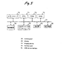
Fig. 5 shows an example configuration of a digital camera serving as
the image supply device 2. In the digital camera, a CPU 71 is a device which
executes a program, to thereby perform processing described by the program.
A ROM 72 is a memory for storing programs and data in advance. A RAM 73
is a memory for temporarily storing a program and data when executing the
program.
A program to be used for controlling individual sections during
photographing operation and a program for effecting communication and
management of image data in accordance with a DPS protocol and an image
transfer protocol are stored, as programs to be executed by the CPU 71, in the
ROM 72 or another unillustrated storage medium.
An imaging device 74 images a subject in accordance with a
command from the CPU 71 and outputs obtained image data.
The memory card 75 corresponds to the storage medium 24 shown in
Fig. 1 and is a storage medium for storing image data obtained through
imaging. Semiconductor memory or a magnetic recording device, which is
fixed in a device, may be used in place of the memory card 75.
A USB device interface 76 corresponds to the communicator 21
shown in Fig. 1 and is a device interface circuit specified by the USB.
A bus 77 is a signal channel for interconnecting the CPU 71, the ROM
72, the RAM 73, the imaging device 74, the memory card 75, the USB device
interface 76, the control panel 25, and the display 26. The number of buses
77 and the topology of connection of the CPU 71 to the bus 77 are not
necessarily limited to those shown in Fig. 5.
The control panel 25 and the display 26, which are shown in Fig. 5,
are analogous to those shown in Fig. 1.
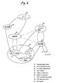
Fig. 6 shows relationships between a plurality of functions of the
image supply device 2. A communication control function 81 is a function for
effecting communication control under an image transfer protocol.
A DPS protocol processing function 82 includes a DPS command
processing function 91, which produces and interprets control information
specified by the DPS protocol; an XML script generating function 92, which
produces an XML script corresponding to the control information; and an XML
server 93, which subjects to syntax analysis the control information described
in an XML.
The XML server 93 may be designed to enable analysis of all
syntaxes in an XML or analysis of only syntaxes used in the DPS protocol. In
such a case, the only requirement for the XML server 93 is to be able to
discern only a tag required to describe an XML script related to the DPS
protocol.
The XML script generating function 92 may be set so as to previously
store templates of XML scripts in the ROM 72 according to the types of control
information items, such as commands, and to generate an XML script showing
control information by editing the template.
A file system management function 83 is a function which stores
image data as an image data file 31 in the memory card 75 serving as the
storage medium 24, in accordance with a predetermined directory structure
and a file structure.
A user interface function 84 is a function for accepting operation of
the control panel 25 performed by the user and displaying various information
items on the display 26.
A setting management function 85 is a function for setting
requirements, such as print processing, in accordance with the user's
operation. A status management function 86 is a function for monitoring
processing statuses of the aforementioned functions. These functions are
realized by the CPU 71 executing the program.
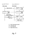
Operations of the individual devices in the system will now be
described. Fig. 7 shows image output processing at the DPS protocol level.
Fig. 8 shows image output processing at the image transfer protocol level.
The image output device 1 and the image supply device 2 each store
files of predetermined names. In a case where the image output device 1 and
the image supply device 2 are physically connected together by the user by
way of the communication path 3, it is detected that an equipment complying
with the DPS protocol is connected as a mating device when the files are
detected on the basis of the PTP. As a result, one of the image supply device
1 and the image output device 2 assures that the other one uses the same
protocol.
After connection processing, the image output device 1 and the image
supply device 2 mutually exchange environmental information including
information about the version of the DPS protocol, the name of the vendor,
version information unique to the vendor, the product name, a serial number,
and the like.
The image supply device 2 acquires, from the image output device 1,
selectable settings; i.e., options, in relation to respective functions of the image
output device 1 which can be set by the image supply device. When the
image output device 1 is a printer, the functions include the setting of print
quality, the setting of a paper size, the setting of a print type, the setting of a
file format of an image data file, settings for printing of a date, settings for
printing of a file name, the setting of image optimization processing, the setting
of a print layout, settings for fixed-size printing, and settings on cropping.
When the image output device 1 has extensions for the respective functions,
options of the settings pertaining to the respective functions, including the
extensions as options, may be collectively reported to the image supply device
2.
After then, when a predetermined operation has been performed by
way of, e.g., the control panel 25, the image supply device 2 transmits an
image output job start command to the image output device 1 by way of the
communication path 3 (step S1).
At that time, in the image supply device 2, the communication
controller 22 produces and transmits an XML script of an image output job start
command "DPS_StartJob" in accordance with the DPS protocol. Here, image
data which are objects of image output are specified within the XML script.
The image output job start command "DPS_StartJob" includes the
next job requirement setting information and image output information.
As required, the job requirement setting information include quality
information for setting the quality of an image output pertaining to a current job,
paper type information pertaining to a current print job, paper size information
pertaining to a current print job, image format information, image processing
setting information, and page layout information.
As required, the image input information include cropping area
information for specifying an area required when cropping operation is
performed, an object ID of image data, copy number information pertaining to
each image, a job ID unique to each job, path information pertaining to image
data or a job specification file, and repeated supply count information
pertaining to each image data (i.e., information showing the number of times
identical image data are consecutively supplied to the image output device 1).
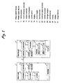
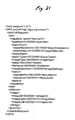
Fig. 9 shows an example XML script of an image output job start
command "DPS_StartJob". A job tag is a tag to be used for specifying one
job. Here, when a reference is made to an XX tag, the tag designates both a
<XX> tag and a </XX> tag (the same also applies to any counterparts in the
following descriptions). A jobConfig tag and a printInfo tag are arranged
below the job tag. The jobConfig tag is for specifying job requirement setting
information.
In the script shown in Fig. 9, a quality tag, a paperSize tag, a
paperType tag, a fileType tag, a date tag, a fileName tag, an imageOptimize
tag, and a layoutltem tag are arranged below the jobConfig tag.
The quality tag is for specifying quality information, such as a
standard, a draft, or a fine. The paperSize tag is for specifying paper size
information pertaining to a current job, such as an A4-size. A paper size is
specified by a predetermined numeral (e.g., 02010000). The paperType tag
is for specifying paper type information pertaining to a current job, such as
standard paper or photographic paper. The paper size is specified by a
predetermined numeral (e.g., 03020000). The fileType tag is for specifying
image format information pertaining to a current job, such as EXIF, JPEG,
TIFF, and GIF, and an image format is specified by a predetermined numeral
(e.g.,04150000).
The date tag is for specifying whether or not date information
specified by a printInfo tag is to be printed. The fileName tag is for specifying
whether or not the file path information specified by the printInfo tag is to be
printed. The "imageOptimize" tag is for specifying image optimization setting
information showing whether or not image optimization is to be effected. The
layoutltem tag is for specifying a page layout of a current job. An image
format is specified by a predetermined numeral (e.g., 08010000).
The printInfo tag is for specifying image output information. An
image tag is arranged at a position lower than the printInfo tag. The image
tag is for specifying an image which is an object of image output. In the script
shown in Fig. 9, an imageID tag and an imageDate tag are arranged at a
position lower than the image tag. The imageID tag is for specifying an object
ID of image data which are objects of image output. The imageDate tag is for
designating a date to be printed beside an image.
The script shown in Fig. 9 includes only one image tag. However, in
a case where a plurality of images are to be output, an image data object ID is
specified for each of the plurality of images by the image tag. When a single
image is to be output repetitively a plurality of times, a copies tag is arranged
subsequent to an image tag of the image, whereby the number of times
feeding operation to be repeated is specified.
A dps tag shown in Fig. 9 is a tag which shows an XML script
pertaining to a DPS and takes, as an attribute, an URL (Uniform Resource
Locator) which is a location at which name space information to be used for
DPS is stored.
Logically, the communication controller 22 of the image supply device
2 transmits the XML script of the job start command in accordance with a DPS
protocol. However, the communication controller 22 converts the XML script
into a command of an image transfer protocol and processes that command on
the image transfer protocol level.
Specifically, the communication controller 22 of the image supply
device 2 first transmits a file transfer request command
"RequestObjectTransfer" (step SS1) in accordance with the image transfer
protocol. The command is transmitted to the image output device 1 by way of
the USB layer and the physical layer.
In the image output device 1, the communication controller 12
transmits a command "GetObjectInfo" for inquiring an attribute of a file to be
transferred upon receipt of the file transfer request command
"RequestObjectTransfer" in accordance with the image transfer protocol (step
SS2). The command is transmitted to the image supply device 2 by way of
the USB layer and the physical layer.
In the image supply device 2, the communication controller 22
transmits file information about an XML script of a command "DPS_StartJob"
(a file format, a file volume, or the like) upon receipt of a command
"GetObjectInfo" in accordance with the image transfer protocol (step SS3).
The file information is transmitted to the image output device 1 by way of the
USB layer and the physical layer.
In the image output device 1, the communication controller 12
specifies the XML script upon receipt of the file information in accordance with
the image transfer protocol, thereby transmitting a file acquisition command
"GetObject" (step SS4). The file information is transmitted to the image
supply device 2 by way of the USB layer and the physical layer.
In the image supply device 2, the communication controller 22
transmits a specified file (an XML script of a command "DPS_StartJob") upon
receipt of the command "GetObject" in accordance with the image transfer
protocol (step SS5). The file is transmitted to the image output device 1 by
way of the USB layer and the physical layer.
In the image output device 1, the communication controller 12
receives the file in accordance with the image transfer protocol, thereby
receiving the command "DPS_StartJob" at a DPS protocol layer.
Here, the image output device 1 is a printer shown in Figs. 3 and 4.
In a case where the image supply device 2 is a digital camera shown in Figs. 5
and 6, communication under a DPS protocol is effected by the DPS protocol
processing functions 52, 82 and communication control functions 51, 81.
Communication under an image transfer protocol is performed between the
communication control function 51 and the communication control function 81.
Next, the image output device 1 interprets an XML script of the
acquired image output job start command (step S2), and image data which are
objects of image output, the objects being described in the XML script, are
acquired from the image supply device 2 (step S3).
In the first embodiment, after an image output job start command has
been received from the image supply device 2, the image output device 1
controls a processing flow of the image output job. Specifically, the image
output device 1 manages progress in image output processing, and
information and image data, both being required for image output processing,.
are acquired from the image supply device 2, as required.
At that time, in the image output device 1, the communication
controller 12 specifies an image data file 31 by an object ID (corresponding to
an object ID in the PTP) described in the XML script in accordance with the
DPS protocol, thereby issuing the file acquisition command "DPS_GetFile" of
the XML script. An object ID in a PTP pertaining to a certain object (i.e., an
object handle) and an object ID in the DPS protocol may be set to a single
value or different values. When the object IDs have different values, the
object ID of the DPS protocol and the object ID of the PTP are mapped, as
necessary.
Fig. 10 shows an example XML script of the file acquisition command
"DPS_GetFile" used in the first command. The getFileRequest tag is a tag
showing a file acquisition command. The filelD tag and a buffPtr tag are
arranged at positions lower than the getFileRequest tag. The filelD tag is for
specifying an object ID of a file which is an object of acquisition. The buffPtr
tag is for specifying a pointer of a buffer to be used for receiving the acquired
file.
The communication controller 12 converts the file acquisition
command "DPS_GetFile" of the DPS protocol into a file acquisition command
"GetObject" of the image transfer protocol and then transmits the
thus-converted command. The command is transmitted to the image supply
device 2 by way of the USB layer and the physical layer.
In place of the file acquisition command "DPS_GetFile" to be used for
acquiring all files, a partial file acquisition command "DPS_GetPartialFile" to be
used for acquiring a part of a file may be transmitted several times, to thereby
acquire the overall file. In such a case, the partial file acquisition command
"DPS_GetPartialFile" is converted into a command "GetPartialObject" of the
image transfer protocol.
In the image supply device 2, the communication controller 22 reads
a file (i.e., an image data file 31 ) of a specified object ID upon receipt of the
command "GetObject" in accordance with the image transfer protocol and
transmits the file. The file is transmitted to the image output device 1 by way
of the USB layer and the physical layer.
In the image output device 1, when the communication controller 12
has received the file in accordance with the image transfer protocol, the file is
also considered to have been received by the DPS protocol layer.
Here, when the image output device 1 is the printer shown in Figs. 3
and 4 and the image supply device 2 is the digital camera shown in Figs. 5 and
6, the DPS protocol processing function 52 and the communication control
function 51, both belonging to the image output device 1, and the
communication control function 81 and the file system management function
83, both belonging to the image supply device 2, are used for acquiring the
image data.
In the image output device 1, when the image data are acquired, an
image based on the image data is output (step S4). At that time, in the image
output device 1, the output controller 13 and the output mechanism 14 perform
the image output processing.
Here, when the image output device 1 is the printer shown in Figs. 3
and 4, the image processing function 53, the print data generating function 54,
and the print control function 55 are used for image output processing.
In this embodiment, an extension tag to be used for adding an
extended function after prescription of the protocol is used in the DPS protocol
at the time of generation and exchange of control information.
When a certain function of the DPS protocol is extended, the image
supply device 2 and the image output device 1 produce control information,
which is an XML script, in accordance with an XML syntax, by insertion of an
extension tag for specifying use of the extended function while an existing tag
representing the function is left as is.
At that time, the image supply device 2 and the image output device 1
insert an extension tag into a nest level which is lower in level than the existing
tag representing the function, or insert an extension tag in association with the
existing tag which specifies image data to be processed by that function. For
instance, the extension tag is inserted immediately before, immediately after,
or into an element including the existing tag that specifies image data.
More specifically, in the image output device 1 serving as, e.g., a
printer, the CPU 41 operates in accordance with a predetermined control
program stored in a recording medium; e.g., the ROM 42. When a certain
function of the DPS protocol remains extended, the existing tag representing
the function is left in the XML script, and a script is generated by insertion of an
extension tag corresponding to the extension. As mentioned above, the CPU
41 operates in accordance with a predetermined control program, thereby
implementing an XML script generating function 62.
In the image supply device 2 serving as, e.g., a digital camera, a CPU
71 operates in accordance with a predetermined control program stored in a
recording medium; e.g., the ROM 72. When a predetermined function of the
DPS protocol remains extended, an existing tag representing the function is
left in the XML script, and an extension tag corresponding to the extension is
inserted, to thereby generate a script. As mentioned above, as a result of the
CPU 71 operating in accordance with the predetermined control program, an
XML script generating function 92 is implemented, and second script
generation means is implemented by the XML script generating function 92.
In the first embodiment, an extension tag to be used for specifying
use of image processing unique to the vendor is used as an extension tag for
adding an extended function to the protocol after prescription of the protocol.
Such image processing includes processing to be effected by an auto photo
fine (APF) function, processing to be effected by a print image matching (PIM)
function, and processing to be effected by an EXIF printing function.
In connection with the first embodiment, there will be described, as an
example, a case where processing of an image, which is an object of image
output, is extended by the PIM function.
First the PIM function will be described. By the PIM function, image
data pertaining to an image captured by an imaging device, such as a digital
camera, and output control data to be used for controlling an image output
device, such as a color printer, at the time of outputting of an image are
associated with each other and recorded as a single image file. The output
control data include a print control command, image processing control data
serving as a parameter to be used during image processing or the like. When
supplied with image data and an image file having output control data, the
image output device, such as a color printer, subjects the image data to image
processing on the basis of the output control data, thereby outputting (printing)
an image on the basis of the image data that have undergone image
processing.
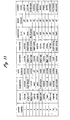
Values of respective parameters included in the image processing
control data are set in accordance with a photographing scene. Fig. 11 is a
view showing parameters of the image processing control data used for the
PIM function and example values of the parameters. Preset parameters are
prepared beforehand in accordance with eleven types of photographing
scenes. These preset parameters include seven types of parameters; that is,
"contrast", "brightness", "color balance", "saturation", "sharpness", "memorized
color" and "noise removal". These preset parameters are prepared by the
vendor of the digital camera. In addition, the user can set and register
desired parameter sets. In addition to including the previously-described
image processing control data, the image file also includes as output control
data photographing requirements, such as a gamma value, a target color
space, an exposure time set at the time of photographing operation, a white
balance, a lens stop, a shutter speed, and a focal length of a lens, all
belonging to a digital camera.
Fig. 12 is a view showing an example configuration of the image file.
The image file has a file structure complying with an image file format standard
(EXIF) for a digital camera. Specifications of the EXIF file are defined by the
Japan Electronics and Information Technology Industries Association (JEITA).
In the EXIF file, in addition to the image data which have been converted into a
JPEG format, there is stored information pertaining to conditions when the
image data is obtained, such as exposure information, lens stop information,
GPS information or the like. The EXIF printing function enables printing with
image processing based on the imaging conditions.
Specifically, the image file has an image data storage area 101 for
storing image data, and an appended information storage area 102 for storing
various appended information items pertaining to the stored image data.
Image data are stored in the image data storage area 101, in a JPEG format.
Appended information including a manufacturer's note 103 is stored in, e.g., a
TIFF format, in the appended information storage area 102. The
manufacturer's note 103 is stored in an undefined area opened to the
manufacturers of digital cameras. In the first embodiment, the image
processing control data are stored as the manufacturer's note 103. A file of
EXIF format employs a tag for specifying respective data sets. A "makerNote"
tag is allocated to the manufacturer's note 103.
In the first embodiment, the image file is determined as a file of EXIF
format. However, the file format is not limited to the EXIF format. Any
format can be employed, so long as the format has a structure for enabling
integration of image data and image processing control data.
The manufacturer's note 103 includes print matching data to be
described later. The print matching data correspond to image processing
control data. A "printMatching" tag is allocated to the image processing
control data.
Fig. 13 is a view showing the data structure of the manufacturer's
note 103 in the image file. Fig. 14 is a view showing the data structure of the
print matching data defined in the manufacturer's note 103 shown in Fig. 13.
As shown in Fig. 13, areas in the manufacturer's note 103 where
respective data sets are stored are specified by offset values derived from a
top address in a data storage area of the manufacturer's note 103. The
manufacturer's note 103 includes the name of a manufacturer (six bytes) at the
top address, followed by a backup area (two bytes), the number of entries of a
local tag (two bytes), and respective local tags (each having 12 bytes). The
name of the manufacturer is appended with a terminal code "0x00"
representing a character termination sequence.
The data structure of the print matching data shown in Fig. 13 is as
shown in Fig. 14. The print matching data include a print matching identifier
showing storage of a print matching parameter, the number of parameter
settings "n" showing the number of parameters set in the print matching data,
parameter numbers previously assigned to parameters which are objects of
setting, and parameter setting values set in the parameters which are objects
of setting. The parameter numbers are, e.g., two-byte information; and the
parameter settings are four-byte information. The image output device
acquires the parameter values set by the print matching data as image
processing control data.
The image file pertaining to the PIM function is configured in the
manner as mentioned above.
There will now be described generation of an XML script serving as
control information when an image is output through use of the PIM function of
the image output system according to the first embodiment. Fig. 15 is a
flowchart for describing generation of an XML script serving as control
information when a PIM function exists as an extended function of an image
optimizing function which is one type of image processing function of the
image output system according to the first embodiment.
When the image supply device 2 is taken as an imaging device, such
as a digital camera having a PIM function, the previously-described image file
having the image data and output control data is recorded on a recording
medium 24 of the image supply device 2.
The image supply device 2 determines whether or not there is an
extended function which can be used by the image optimizing function when
the image optimizing function is specified under a situation where image output
operation, such as printing, is performed in accordance with the user's
operation (step S21).
When use of the PIM function is determined to be possible, the image
supply device 2 determines, on the basis of the environmental information
about the image output device 1 and/or optional setting values of the functions,
whether or not the image output device 1 can use the PIM function, which is an
extension of the image optimizing function that can be used by the image
supply device 2 (step S22). For instance, the image supply device 2
determines whether or not the extended function is usable in accordance with
version information unique to the vendor from among the environmental
information items. Specifically, a determination as to whether or not the
extended function is usable is indicated by the version information unique to
the vendor.
When having determined the image output device 1 to be able to use
the PIM function, the image supply device 2 inserts an "imageOptimize2" tag,
which is an extension tag to be used for specifying image output through use
of the PIM function, into a nest level which is lower in level than an image
optimize tag, the tag being an existing tag for optimizing an image in the image
output job start command "DPS_StartJob", thereby producing an XML script
serving as control information (step S23). The name of the extension tag is
not limited to "imageOptimize2" and can be freely specified by each vendor.
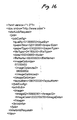
Fig. 16 is a view showing an example image output job start
command "DPS_StartJob" generated by the image supply device 2. An
element "<imageOptimize2> 08000000 </imageOptimize2>" including an
"imageOptimize2" tag which is an extension tag is provided in an element
"<imageOptimize> 07000000 </imageOptimize>" including the
"imageOptimize" tag, which is an existing tag. A determination is made as to
whether or not image output using the PIM function is to be executed, by a
value ("08000000" in the embodiment) specified by the "imageOptimize2" tag,
which is an extension tag. In this case, the object ID specified by the image
ID tag is taken as an object ID of the previously-described image file including
output control data.
When the image supply device 2 does not have any extended
function that can use the image optimizing function and when the image output
device 1 cannot use the extended function of the image optimizing function
that the image supply device 2 can use, an image output job start command
"DPS_StartJob" is generated without insertion of an extension tag (step S24).
The thus-generated image output job start command "DPS_StartJob"
is transmitted to the image output device 1 from the image supply device 2 by
way of the communication path 3 (step S25).
When the image output device 1 supplied with the image output job
start command "DPS_StartJob" is a type complying with the image output
using the PIM function, the image output device 1 ascertains the
"imageOptimize2" tag as a tag for specifying the image output using the PIM
function. On the basis of the value specified by the tag, the image output
device 1 determines whether or not the image output using the PIM function
(e.g., printing) is to be performed. When a determination is made that the
image output using the PIM function is to be performed, the image output
device 1 subjects image data of the image file to image processing on the
basis of output control data pertaining to an image file acquired from the image
supply device 2, thereby outputting (e.g., printing) an image on the basis of the
image data that have undergone image processing.
If the image output device 1 is not a type complying with the image
output using the PIM function, the image output job start command that does
not include any extension tag is received, and an unextended function is used
to perform image output operation in accordance with the image output job
start command.
If an image output job start command including an extension tag is
erroneously received in a case where the image output device 1 is not a type
complying with the image output using the PIM function, the image output
device 1 ascertains the "imageOptimize2" tag, which is an extension tag, as an
undefined tag and ignores an element including the tag in accordance with the
regulation of the XML, thereby outputting (e.g., printing) an image on the basis
of the image data. At that time the image output device 1 determines whether
or not image optimization operation is to be performed, on the basis of the
value specified by the "imageOptimize" tag, which is an existing tag. When
image optimization is determined to be performed, the image data in the image
file may be subjected to predetermined image processing, thereby outputting
an image on the basis of the image data that have undergone image
processing.
In the example image output job start command "DPS_StartJob"
shown in Fig. 16, the extension tag is provided immediately below the existing
tag. An element including the extension tag may be arranged for each image
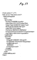
file. Fig. 17 is a view showing another example image output job start
command "DPS_StartJob" generated by the image supply device 2. Aside
from the element "<imageOptimize> 07000000 </imageOptimize>" including
the "imageOptimize" tag which is an existing tag, an element
"<imageOptimize2> 08000000 </imageOptimize2>" including the
"imageOptimize2" tag, which is an extension tag, may be provided in
association with an element including the image ID tag which specifies an
image file. Even in such a case, a determination is made as to whether or not
the image output using the PIM function is specified by the value ("08000000"
in this embodiment) specified by the "imageOptimize2" tag, which is an
extension tag. Further, the object ID specified by the imageID tag is taken as
an object ID of the foregoing image file including output control data.
In the first embodiment, a determination is made as to whether or not
the extended function is used in accordance with the value specified by the
extension tag. Alternatively, settings may be effected such that the extended
function is used by only the extension tag without specification of such a value.
Namely, in such a case, when the extension tag is inserted, the extended
function is executed.
In the first embodiment, a determination is made as to whether or not
the extended function of image processing is to be performed on the basis of
output control data in the image file, by an extension tag for the PIM function,
and image processing control data provided in the image file are used for
image processing. Alternatively, the value of the parameter in the output
control data may be set directly by the extension tag for the PIM function.
In the first embodiment, when a certain function of the DPS protocol is
extended, the image supply device 2 and the image output device 1 may
generate control information by arranging an extension tag prior to the existing
tag representing the function in the XML script constituting the control
information, in accordance with an XML syntax. In this case, the extension
tag is interpreted prior to interpretation of the script. Hence, the function of
the existing tag can be made easy to invalidate.
In the first embodiment, image processing is performed on the basis
of the output control data provided in the image file. Instead of or in addition
to this, the image supply device 2 may specify parameters for image
processing by an extension tag. When image processing is specified by the
extension tag, the image output device 1 may subject image data to the image
processing specified by the extension tag from among the predetermined
image processing operations, thereby outputting an image on the basis of the
image data that have undergone image processing.
As mentioned above, according to the first embodiment, when a
predetermined function in the image output control protocol is extended at the
time of generation of a series of scripts made by describing, in a markup
language, control information pertaining to image output on the basis of the
image output control protocol, the image output device 1 and the image supply
device 2 generate a script by leaving within the scripts an existing tag
representing the function and inserting an extension tag corresponding to the
extension. The thus-generated scripts are exchanged between the mating
device by way of the communication path 3.
As a result, a function can be easily added to the protocol after
prescription of the protocol by utilization of a characteristic of the markup
language while compatibility among a plurality of vendors is maintained.
Specifically, when the equipment which interprets a script does not have any
extended function, the equipment performs processing on the basis of an
existing tag. In contrast, when equipment which interprets a script has an
extended function, the equipment performs processing on the basis of a tag for
the extended function.
According to the first embodiment, the image output device 1 and the
image supply device 2 generate scripts by inserting an extension tag to a nest
level lower than the existing tag within the script.
As a result, the tag of the extended function is arranged at a level
lower than the tag of the existing function (i.e., between the start tag and the
end tag), and hence a determination can be readily made as to whether or not
the extended function is set for a certain function.
Further, according to the first embodiment, the image output device 1
and the image supply device 2; generate scripts by inserting an extension tag in
association with the image data which are to be processed by the function
extended in the script.
As a result, switching can be made, on a per-image basis, between
use of the extended function and non-use of the extended function.
Further, according to the first embodiment, an XML which enables
additional definition of a document type is used as a markup language for
describing control information.
As a result, the function can be more readily added after prescription
of the protocol by utilization of the extensibility of the syntax of the markup
language.
Moreover, according to the first embodiment, the image output device
1 and the image supply device 2 communicate, as control information
pertaining to image output and in the form of a series of scripts described in a
markup language, a control command for image output processing, a response
to the control command, and notification of a status of the device.
As a result, in relation to a control command, a response to the
control command, and notification of status of the device, functions can be
readily added to the protocol after prescription, by utilization of extensibility of
the syntax of the markup language while compatibility between a plurality of
vendors is maintained.
According to the first embodiment, the image output device 1 and the
image supply device 2 communicate, as a series of scripts described in a
markup language, a script which does not include image data to be an object
of image output and includes only control information pertaining to image
output.
As a result, the control information described in a markup language
can be communicated independently of the data which are to become an
object of image output, without modifying the existing format of data which are
to be an object of image output.
According to the first embodiment, a tag for specifying image
processing unique to the vendor is used as an extension tag.
As a result, image processing having various characteristics, the
characteristics differing from one vendor to another, can be specified at the
time of image output.
According to the first embodiment, when image processing is
specified by the extension tag, the image output device 1 subjects image data
to image processing on the basis of the image processing control data
recorded on the file of image data, thereby outputting an image on the basis of
the image data that have undergone image processing.
As a result, an image processing function using image files, the files
having image data and image processing control data, can be readily added.
According to the first embodiment, when image processing is
specified by the extension tag, the image output device 1 can subject image
data to an image processing operation specified by the extension tag from
among predetermined image processing operations, thereby outputting an
image on the basis of the image data that have undergone image processing.
This case enables easy addition of the function for selecting any one
from the previously-prepared image processing operations and subjecting
image data to the selected image processing operation.
As mentioned above, according to the first embodiment, the image
output device 1 and the image supply device 2 communicate control
information pertaining to image output as a series of scripts described in a
markup language by way of the communication channel 3. As a result,
correction of the protocol after prescription can be facilitated by utilization of
extensibility of the syntax of a markup language while compatibility among a
plurality of vendors is maintained.
According to the first embodiment, each of the communication
controllers 12, 22 serves as a first entity for interpreting a DPS protocol to be
used for exchanging control information pertaining to image output described
in a markup language; a second entity which is located at a level lower than
the first entity and interprets a PTP to be used for managing the image data file
stored in the image supply device 2 and transferring the image data to the
image output device 1; and a third entity which is located at a level lower than
the second entity and controls a physical layer (a USB in this embodiment) of
the communication channel 3. As a result, various existing protocols can be
used at hierarchical levels lower than the PTP. When correction of a protocol
pertaining to image output is desired after the protocol has been prescribed,
the only requirement is to amend the DPS protocol, and hence the amount of
correction can be reduced.
According to the first embodiment, the communication controllers 12,
22 convert the DPS protocol of the first entity into the image data file
management transfer protocol or vice versa in accordance with the kind of
image data file management transfer protocol of the second entity (PTP in the
embodiment) at a wrapper layer. As a result, the wrapper layer absorbs a
difference between the adopted image data file management transfer protocols.
Hence, when correction of a protocol pertaining to image output is desired after
having been prescribed, the only requirement is to amend the image output
control protocol without involvement of any substantial corrections on the
wrapper layer, and hence the amount of correction can be reduced.
According to the first embodiment, the communication controllers 12,
22 communicate, as control information pertaining to image output and in the
form of a series of scripts described in a markup language, a control command
for image output processing, a response to the control command, and
notification of a status of the device (including a job status). As a result, a
control command which is on a text basis and easy to read, a response to the
control command, and notification of status of the device can be
communicated, and the protocol can be made easy to correct after prescription
while compatibility between a plurality of vendors is maintained.
According to the first embodiment, the communication controllers 12,
22 communicate, as a series of scripts described in a markup language, a
script which does not include image data to be an object of image output and
includes only control information pertaining to image output. As a result, the
control information described in a markup language can be communicated
independently of the data which are to become an object of image output,
without modifying the format of data to be an object of image output from an
existing format.
According to the first embodiment, the image output device 1 has an
output mechanism 14 for outputting an image, and an output controller 13
which produces, from image data, control data to be used for controlling an
output mechanism and controls the output mechanism on the basis of the
control data. As a result, the image supply device 2 can be dispensed with a
function for producing, from image data, control data to be used for controlling
the output mechanism (e.g., a function included in a conventional printer driver
used in a personal computer), and hence the image supply device 2 can be
made inexpensive.
According to the first embodiment, when the XML server 63 of the
image output device 1 is configured to determine only a tag required to
describe the control information pertaining to image output from among the
tags described in a markup language, the XML server 64 can be implemented
by a small-amount circuit or program, thereby rendering the image output
device 1 inexpensive.
According to the first embodiment, when the XML server 93 of the
image supply device 2 is configured to determine only a tag required to
describe the control information pertaining to image output from among the
tags described in a markup language, the XML server 93 can be implemented
by a small-amount circuit or program, thereby rendering the image supply
device 2 inexpensive.
Like the image output system of the first embodiment, an image
output system according to a second embodiment of the invention is arranged
to use an extension tag to be used for adding an extended function to a DPS
protocol after prescription thereof at the time of generation and exchange of
control information. The second embodiment uses an extension tag for
adding, to an image output control protocol after prescription and as an
extension, a frame-inserted printing function for printing in combination a frame
image and an image of image data.
The basic configuration and operation of the image output system of
the second embodiment are identical with those of the first embodiment, and
hence their explanations are omitted.
The frame-inserted printing function (hereinafter called a "Print Image
Framer (PIF) function") will now be described. Printing utilizing the PIF
function will be hereinafter referred to as PIF printing.
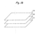
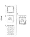
Fig. 18 is a view for describing the concept of the PIF function. Fig.
19 is a view for showing an example print image obtained in the case of PIF
printing. As shown in Fig. 18, when the PIF function is used, a plurality of
images 121, 122, and 123 are printed in a single image area in a
superimposed manner. In such a case, one image 123 is a frame image, and
information pertaining to a transparent area where another image 122 is to be
displayed (e.g., the position and transparency of the area) is described in
frame image data. As shown in Fig. 19, image data pertaining to a
background image 121, image data pertaining to the image 122 which is taken
as an object of printing, and image data pertaining to the image 123 which is a
frame image are merged together, thereby producing image data pertaining to
one image 131. The thus-merged image 131 is printed on the basis of the
image data.
The layout of a target image, a background image, and a frame image
obtained at the time of PIF printing is defined by a layout definition file. Fig.
20 is a view showing an example layout definition file. Header information (a
portion starting with a head "HEADER") and page information (a portion
starting with a head "PAGE") are described in the layout definition file.
The header information includes information about the layout
definition file. For instance, the header information includes a variable
"HdKeyWord," a variable "HdDirection," a variable "HdSound," a variable
"HdThumbnail," a variable "HdPhysicalPaperSize," and a variable "HdMargins."
The variable "HdKeyWord" has, as a value, a specific keyword
pertaining to a page layout or a user's desired keyword pertaining to the same.
For instance, the variable is described as "Christmas" or "Greeting" in Fig. 20.
Characters of a desired character code as well as half-size alphanumeric
characters can be used for the keyword. The layout definition file is retrieved
on the basis of the keyword(s) determined by the variable "HdKeyWord."
The variable "HdDirection" has, as a value, information about a
display direction of the page layout. The display direction is the orientation of
a page layout when the page layout is displayed in a finder or display screen of
a digital camera or printed. For instance, the variable is defined as a portrait
orientation or a landscape orientation.
The variable "HdSound" has, as a value, sound file information; that is,
a pointer of a sound file associated with the layout definition file. The value of
the variable "HdSound" is defined as, e.g., the name of a sound file (e.g.,
"GSOUND.PCM" as shown in Fig. 20) and the name of a relative path (e.g.,
"
EPUDL
" as shown in Fig. 20). The name of an absolute path may also be
used in place of the name of a relative path. A method for representing a file
pointer can be made analogous to that employed in the embodiment.
As mentioned above, the layout definition file can be associated with
the sound file. For instance, when the layout definition file is output to the
outside, the sound file may also be output. The sound file is reproduced at a
predetermined time. For instance, when the page layout described in the
layout definition file is displayed in the finder or display section of the digital
camera or the display section of the printer and when a page design including
the page layout is printed, sound or the like recorded in the sound file is
automatically reproduced.
The variable "HdThumbnail" has, as a value, thumbnail information or
a pointer of an image data file of a thumbnail of the page layout. The
thumbnail image is prepared through use of a specific device (a personal
computer, a portable cellular phone, a digital camera, or a printer). A list of
page layouts where thumbnail images are arranged may be displayed or
printed in accordance with the user's operation.
The variable "HdPhysicalPaperSize" has, as a value, physical page
size information; that is, a paper size perfectly matching the size of the page
layout when the page layout is printed.
The variable "HdMargines" has, as a value, print margin information;
that is, information showing the size of a margin of print paper which is to be
left at the time of printing of a page layout. For instance, as shown in Fig. 20,
when the value of the variable "HdMargines" is set to "3, 3, 3, 3," printing is
performed such that a margin of 3 mm is left along the top, bottom, and either
side of rectangular paper. Numerals of the print margin are not limited to
positive values and may assume zero or negative values. In such a case,
printing is performed without formation of margins.
The page information provided in the layout definition file includes
information about the attribute of a page layout. For instance, the page
information includes a function "Draw Picture," a function "Draw String," a
function "Draw Line," or the like.
The function "Draw Picture" is to render an image while information
about an image area or the like information is taken as an argument.
A first argument to the function "Draw Picture" is an image file pointer
for linking a file of a target image to be applied with an image area.
When the target image is determined at the time of generation of the
layout definition file, the value of the image file pointer of the first argument is
taken as the file pointer of the target image. When the target image is not
determined at the time of generation of the layout definition file, the value is set
to null.
When the background image 121 to be applied to the image area of
the page layout has been determined in advance, the file pointer of the image
is described as the first argument. Alternatively, the type of an image to be
applied may be identified by an extension of a file name. For instance, in the
case of a background image, the only requirement is to determine the type of
an image as an extension "EFF." If the target image has not yet been
determined at the time of generation of the layout definition file, a target image
is specified within the print job start command.
A second argument to the function "Draw Picture" is a photo ID of the
image area. When the image to be applied has not yet been determined, the
value of the photo ID is set to an integer of one or more. If the image to be
applied has already been determined, the value of the photo ID is set to zero.
Third to sixth arguments to the function "Draw Picture" are X-Y
coordinate values of two points located on a diagonal line showing the outer
shape of the rectangular image area. The outside shape of the image area is
not limited to a rectangle but may assume a shape such as a polygon, a
complete circle, or a flat oval. The method for specifying the outside shape of
the image area is not limited to a method for describing coordinates, and may
be, e.g., a functional expression showing a boundary line.
A seventh argument to the function "Draw Picture" is rotational degree
information showing the extent to which an image to be applied to the image
area is to be rotated. The rotational degree information can be set within a
predetermined area (e.g., 0° to 360°).
An eighth argument to the function "Draw Picture" is a numeral for
specifying a fitting rule to be applied to an image. The fitting rule includes,
e.g., a rule for applying an image in an unmodified form regardless of whether
or not a margin arises in an image area and a rule for applying an image such
that a user's desired range is displayed while a user's desired aspect ratio is
maintained without causing any margin in the image area.
A ninth argument to the function "Draw Picture" is a numeral for
specifying a positioning rule for determining a position in the image area where
an image is to be arranged. The positioning rule is, e.g., upper-left-align (a
method for aligning the upper left top of an image to the upper left top of an
image area) or center-align (a method for aligning the center of an image to the
center of an image area).
The function "Draw Strings" of the page information is for rendering
ornaments specified by arguments, such as characters or graphics, at the
positions specified by the arguments. The structure of the function "Draw
Strings" changes depending on the nature of ornaments to be applied to the
page layout.
A First argument to the function "Draw Strings" is a pointer of an
image file used for application of ornaments. A second argument to the
function "Draw Strings" is a photo ID of the image area.
A third argument to the function "Draw Strings" is first ornament
information showing details of ornaments. The third argument is described as
"%G, %d, %y" in Fig. 20. The value "%G, %d, %y" shows a character string
which represents a date on which images of an image file were photographed,
the date being described in the image file as use image information. A user's
desired character string may be used in place of a character string showing the
date of photographing.
Fourth to seventh arguments to the function "Draw Strings" are
ornament application position information showing positions where the
ornaments specified by the first ornament information are to be located. The
fourth to seventh arguments are described as "100, 200, 200, 300" in Fig. 20 in
the same format as that according to which the outside of the image area is
specified.
Eighth through twelfth arguments to the function "Draw Strings" are
second ornament information showing attributes of ornaments to be applied.
The eighth through twelfth arguments are shown as "Mincho, 0, 128, 128, 128"
in Fig. 20. The attributes described by the eighth through twelfth arguments
are attributes of characters showing the date of photographing to be
embedded in the above-described position where ornaments are to be applied.
Here, the arguments show that a character string showing the date of
photographing is described in a "Mincho" font, the size of eight point, an R
color of a 128-bit value, a G color of a 128-bit value, and a B color of a 128-bit
value.
Of the page information, the function "Draw Line" is for rendering a
line to be applied to the page layout. The function "Draw Line" assumes eight
arguments, wherein first and second arguments show coordinates of the start
point of a line and third and fourth arguments show coordinates of the end
point of the line. Fifth to eighth arguments show attribute information about a
line to be rendered (e.g., the thickness of a line and RGB values). The fifth to
eighth arguments are described as "5, 255, 0, 0" in Fig. 20. The thickness of
the line is five points. In relation to the color of the line, the R color assumes
a value of 255; the G color assumes a value of 0; and the B color assumes a
value of 0.
When PIF printing is to be performed, the previously-described layout
definition file is specified by a print job start command. The image output
device, such as a printer, merges the plurality of images 121, 122, and 123 in
the layout on the basis of the layout definition file. The thus-merged image is
printed.
There will now be described a series of processing operations
including generation of an XML script serving as control information, in the
case where the image output system of the second embodiment performs PIF
printing operation.
In the image supply device 2 serving as a digital camera, a CPU 71
performs the following operations in accordance with a predetermined control
program. In response to the user's operation, the CPU 71 interprets a layout
definition file stored in a recording medium 24 or the like. On the basis of the
result of interpretation, a page layout is generated, and the thus-generated
page layout is displayed on a display device 26.
Subsequently, when a photographing operation is performed by way
of an operation section 25 while the page layout is displayed in a finder or the
display device 26, an imaging device 74 stores, as image data, an image
captured from the view field of the camera at that point in time. The CPU 71
stores the image data captured by the imaging device 74 into a memory 75 as
an image file of predetermined format (e.g., a JPEG format).
Next, the CPU 71 selects image data pertaining to the captured
image as an image to be embedded into the image area (i.e., a target image
area) in the currently-displayed page layout. The CPU 71 generates a print
job start command "DPS_StartJob" to be used for performing PIF printing in
response to a layout definition file of the currently-displayed page layout and
an image data file of the captured image.
Fig. 21 is a view showing an example print job start command
"DPS_StartJob" generated by the image supply device 2.
The print job start command "DPS_StartJob" for PIF printing purpose
specifies an object ID of the image data file of the background image 121 by
the "paperSizeLink" tag serving as an extension tag. An object ID of the
layout definition file is specified by a "layoutLink" tag serving as an extension
tag. A data file (e.g., a file of the extension EFF) of the frame image is
specified by an "imageLink" tag serving as an extension tag. An object ID of a
target image (i.e., the image 122) is specified by an "imageID" tag serving as
the existing tag.
Upon receipt of the print job start command "DPS_StartJob", the
image output device 1 acquires, from the image supply device 2, image data
pertaining to the background image 121, the target image 122, and the frame
image 123 and the layout definition file. Merged image data are generated in
accordance with the page layout described in the layout definition file.
Printing operation is performed on the basis of the image data.
Exchange of the command in the second embodiment can be
effected in the same manner as in the first embodiment, and hence its
explanation is omitted.
As mentioned above, according to the second embodiment, a tag for
specifying frame insertion printing operation which enables combined printing
of a frame image and an image of image data can be used as an extension tag.
Hence, a function for implementing unique frame insertion printing operation
can be added easily.
An image output system according to a third embodiment of the
invention is provided with extension tags for adding extended functions to a
DPS protocol after prescription of the DPS protocol and uses the extension
tags at the time of generation and exchange of control information including
extended functions, as in the case of the first and second embodiments. In
other respects, the image output system of the third embodiment is identical in
configuration and operation with that of any of the embodiments, and hence
repetitive explanation is omitted.
In the third embodiment, the image output device 1 stores in advance,
for each paper size, a correspondence between a printable paper size (e.g.,
A4, B5, B4, or the like) and a paper type prepared by a vendor or a third party
(e.g., plain paper, dedicated paper, or the like) in, e.g., ROM 43. The size of
print paper and a paper type, which are specified by control information
pertaining to image output, are examined. When paper of specified paper
type and size is not available, a notice to this effect (a kind of control
information) is generated through use of an extension tag. The notice is then
transmitted to the image supply device 2.
For instance, the image supply device 2 uses, in the print job start
command "DPS_StartJob" and as extension tags, a "paperSize" tag for
specifying a paper size and a "paperType" tag for specifying a paper type,
thereby specifying a paper size and a paper type, respectively. The print job
start command "DPS_StartJob" is transmitted to the image output device 1.
Upon receipt of the print job start command "DPS_StartJob", the
image output device 1 specifies a paper size specified by the "paperSize" tag
and the paper type specified by the "paperType" tag. By reference to
information about a correspondence between the previously-stored paper size
and the paper type, a determination is made as to whether or not a specified
paper type of the specified paper size is available.
When the specified paper type of the specified paper size is available,
the image output device 1 attempts to initiate a print job in accordance with the
print job start command "DPS_StartJob".
When the specified paper type of the specified paper size is not
available, the image output device 1 generates, as control information, an XML
script including an extension tag indicating an error notice and sends the
control information to the image supply device 2. When the image supply
device 2 is of a type capable of addressing the extension tag of the error notice,
the image supply device 2 detects a setting error of paper type or size upon
receipt of the control information, thereby reporting the error to, e.g., the user.
As mentioned above; according to the third embodiment, the image
output device 1 examines the size and type of print paper specified by the
control information. If the specified paper of the specified size is not available,
control information to this effect is generated through use of the extension tag.
The control information is then transmitted to the image supply device 2. As a
result, in the case where print paper of specified type (e.g., plain paper, mat
paper, or photocopy paper) and specified size is not provided by the vendor or
the third party (i.e., the paper is not manufactured or sold), erroneous printing
can be hindered.
As a fourth embodiment of the invention, there will be described a
case where there are a plurality of image output devices including a printer and
a display. In the display, display correction information is provided in advance
(at the time of manufacturing) so as to correct an image to be displayed in
accordance with PIM information. Accordingly, image data provided with the
PIM function is subjected to image processing based on the PIM information
and the display correction information, and then displayed. In the printer, the
image data provided with the PIM function is subjected to image processing
based on the PIM function, and then printed. As a result, in a case where the
same image data provided with the PIM function is transmitted from the image
supply device to the printer and the display, the printed image and the
displayed image are visually recognized as substantially the same one.
As a fifth embodiment of the invention, it is possible to designate
arbitrary number of image data to which the extension tag (PIM function) is
appended at once. Specifically, when the user designates at least one image
data to which the PIM function is to be appended, from the image supply
device side or the control panel of the image output device, the extension tag
(PIM function) is automatically appended to the designated image data.
As a sixth embodiment of the invention, it is possible to append a
plurality of extended functions 'to at least one image data at once. Specifically,
when the user designates at least one image data to which at least one PIM
function is to be appended, from the image supply device side or the control
panel of the image output device, at least one extension tag (PIM function) is
automatically appended to the' designated image data.
The previously-described embodiments are preferable examples of
the invention. However, the invention is not limited to these embodiments.
The invention is susceptible to various modifications or alterations within the
scope of the invention.
For instance, in the respective embodiments, control information is
described through use of XML which is one of the markup languages.
However, another markup language such as SGML (Standard Generalized
Markup Language) may be used for describing the control information.
In the previously-described respective embodiments, the PTP and the
USB are used at hierarchical levels lower than the DPS protocol level.
However, another protocol, such as a TCP/IP (Transmission Control
Protocol/Internet Protocol) may also be used. At that time, a LAN cable,
Bluetooth, a wireless LAN, or the like may also be used as a transmission
medium.
The command names, the tag names, and the extension tag names
of the DPS protocol used in the respective embodiments are not limited to
those mentioned previously; other names may also be employed. Commands
of the DPS protocol may also be embodied by other commands having the
same function or a combination thereof. Moreover, the function specified by
the extension tag is not limited to that mentioned previously.
In the respective embodiments, the image output device 1 can be
embodied as a printer, and the image supply device 2 can be embodied as a
digital camera for recording a moving image and/or a still image. Alternatively,
the image output device 1 may also be embodied as another recording device
for recording an image on a medium such as paper or a display for projecting
an image of light such as a display. The image supply device 2 may also be
embodied as an electronic device having a built-in digital camera or an
electronic device which receives an image signal. Such an electronic device
includes a mobile telephone, a PDA, a music player, a TV set, a video
recording/reproducing apparatus, a picture phone, a videoconferencing system,
etc. Further, the image supply device 2 may be embodied as a device having
portability or a device not having much portability.
In the respective embodiments, upon completion of transfer of the
image data required for image output from the image supply device 2 to the
image output device 1, a notice indicating that connection with the image
output device 1 can be released may be transmitted from the image output
device 1 to the image supply device 2.
In the respective embodiments, a USB mass storage class may also
be employed as the image data file management transfer protocol in place of
the PTP.
The images described in connection with the embodiments may be
embodied as text images in addition to picture images. Further, the object of
image output may be a text, e.g., a title table or lyrics of a music album, such
as a music CD or a music MD. In this case, for instance, the image supply
device 2 or the image output device 1 acquires text data from a distribution
server on the Internet in accordance with the information recorded on a music
album.