The present invention relates to an illumination arrangement, in particular for a
projection system, or the like, and more particular to an illumination
arrangement for a projection system which employs solid state light sources.
Nowadays, in many electronic appliances display devices are necessary for
displaying information to a user or an audience. Because of the large variety of
different types of electronic appliances having such a display device it became
necessary to develop display devices for which only a limited space and/or a
limited power consumption are available. Therefore, the idea of involving an
array of light emitting diodes (LED) came up, but it was realized at the same time
that known and state of the art light emitting diodes have only a very limited
light output capability. Additionally, the coupling of the generated primary
illumination light emitted by a known light emitting diode to the projection
objects appeared to be rather complicated, as every single light emitting diode
has to be coupled to the projection optics by using independent optical fibres.
It is an object of the present invention to provide an illumination arrangement, in
particular for a projection system, which is capable of using solid state light
source devices having only low light output capabilities and which at the same
time enables an easy and reliable optical coupling of the primary illumination
light from the solid state light source device to projection optics.
The object is achieved by an illumination arrangement according to claim 1.
Preferred embodiments of the inventive illumination arrangement are within the
scope of the dependent subclaims.
The illumination arrangement according to the present invention is adapted for a
projection system, or the like, and comprises a light source device and a light
collecting, integrating and redirecting device. The light source device is adapted
for generating and for emitting primary illumination light. The light collecting,
integrating and redirecting device is adapted for receiving at least a part of said
primary illumination light from said light source device in a direct manner. The
light collecting, integrating and redirecting device is further adapted to redirect
said received primary illumination light so as to obtain directed primary
illumination light. Additionally, said light collecting, integrating and redirecting
device is adapted for outputting said redirected primary illumination light or a
derivative thereof as secondary illumination light. According to the present
invention, said light source device is or at least comprises at least one solid state
light source device. Said light collecting, integrating and redirecting device
comprises at least one light valve device which is adapted for receiving said
redirected primary illumination light and for outputting said secondary
illumination light in a controllable manner. Further, said light collecting,
integrating and redirecting device comprises at least one light integrating device
being adapted for directly receiving and for integrating at least a part of said
primary illumination light generated by and emitted from at least one associated
of said at least one solid state light source devices and for outputting said
redirected primary illumination light or a derivative thereof.
It is therefore a basic idea of the present invention to use at least one solid state
light source device as said light source device. It is a further basic idea of the
present invention to have at least one light integrating device which is adapted
for directly receiving and for integrating at least a part of said primary
illumination light. Therefore, in contrast to prior art systems which use for
instance LED devices together with a multiplicity of interposed fibre optical
elements to collect and redirect the received output light from the LED devices,
solid state light source devices can be used and coupled in an easy and reliable
manner.
There are several possibilities of realizations for said solid state light source
devices. First of all, it is preferred to have the solid state light source device
comprised of a single or-of a plurality of solid state light sources.
If a plurality of solid state light sources is involved said plurality may be built-up
by or may comprise an array of solid state light sources.
It is of particular advantage to involve different kinds of solid state light sources,
in particular if each of which is adapted for generating and for emitting radiation
or light of distinct spectral ranges or colours. In this case, they may be in
particular organized in distinct groups, wherein in particular each group is then
capable of producing radiation or light of a given spectral range or colour.
According to a further advantageous embodiment of the inventive illumination
arrangement each of said solid state light sources is a single light emitting diode
(LED) or a multiplicity of light emitting diodes. Also edge-emitting LEDs (EELED)
or pluralities thereof can be used.
Alternatively or additionally, each of said solid state light sources is a single
vertical cavity surface emitting laser device (VCSEL) and/or a laser diode (LD) or
a multiplicity of vertical cavity surface emitting laser devices and/or laser diodes
(LD).
Alternatively or additionally, each of said solid state light sources is a single
resonant cavity light emitting diode (RCLED) or a plurality of resonant cavity
light-emitting diodes.
To allow most of the primary illumination light generated and emitted by the
light source device to be used and to be optically coupled to projection optics and
to avoid primary illumination light to escape from the location of its generation
without being collected it is also proposed that said light integrating device and
said at least one associated solid state light source device are disposed in closed
spatial proximity or relationship to each other.
It is in particular suggested that said light integrating device and said at least
one associated solid state light source device are disposed in direct mechanical
contact to each other.
In contrast, the collecting property of the light integrating device can be
increased if according to a further preferred embodiment said light integrating
device and said at least one associated solid state light source device are adapted
to have a gap structure between them, in particular an air gap, an evacuated
gap, the gap width of which being small in particular compared to the cross-sections
of the light integrating device and/or said at least one associated solid
state light source device.
According to this measure and in accordance to the refraction law of Snellius
even more light generated and emitted by the associated solid state light source
device can be collected and integrated by said light integrating device.
To further increase the light transmission from the associated solid state light
source devices to the associated light integrating devices it is proposed in
accordance to a further preferred embodiment of the present invention that said
light integrating device has a light incidence aperture, that said associated solid
state light source device has a light emitting aperture, and that said light
emitting aperture is less than or equal to said light incidence aperture with
respect to their diameter or cross-section area. According to this particular
measure the cross-section or the area of the light incidence aperture of the light
integrating device gets the best illumination with respect to the primary
illumination light generated by and emitting from the associated solid state light
source device.
There are different possibilities of building-up said light integrating device. First
of all said light integrating device may be a light pipe, an integrator rod, and/or
the like.
Said light integrating device may be a solid rod, made in particular of plastic,
glass, or an other optical transparent material.
Alternatively, said light integrating device may be built-up as a hollow tube
device or tube element having reflecting or mirrored inner walls or side faces.
According to the above-mentioned measures, said light integrating device acts as
a light guide for the received primary illumination light.
Advantageously, said light integrating device has a square, rectangular,
hexagonal or equilateral triangular cross-section to obtain a uniform
distribution. Oval or circular cross-sections are also possible if there are
uniformity restrictions possible.
Additionally or alternatively, said light integrating device may be built-up as a
light mixing device, in particular as a beam splitter device, a colour cube device,
and/or the like.
In this case said light integrating device may have a plurality of light incidence
apertures and at least one light output aperture.
According to this measure it is possible to use said light integrating device as an
input stage for the primary illumination light of different and separated solid
state light source devices, the primary illumination light of which entering
different light incidence apertures and the mixing light leaving the light
integration device after being mixed within said light integrating device and
exiting the light integrating device from said light output aperture.
Of course, different light integrating devices can be combined with each other so
as to combine and integrate and redirect primary illumination light stemming
from different and spatially separated different solid state light source devices to
yield a secondary illumination light having best illumination and projection
properties.
In the following these and further aspects of the present invention will be more
elucidated:
Solid state light sources (SSLS) present a number of advantages for rear- and
front-projector engines when compared with traditionally used high pressure
lamps. In particular, SSLSs allow colour management at the source level; they
allow a better colour saturation, and they have a much longer lifetime. Moreover,
SSLSs allow the design of new light engine architectures leading to more compact
and potentially cheaper devices.
The improvement of the lumen output, e. g. of light emitting diodes (LEDs), make
them a natural tentative candidate to be used in projectors. As the light emitted
by a single LED is not sufficient for some projector applications, the idea of
collecting the light emitted by an array of LEDs and in redirecting it through the
light valve came up. If the LED array covers a surface greater than the panel
surface, light pipes commonly are used to collect the light of each individual
LED. This approach requires a precise and costly assembly.
Instead, it is proposed to optimise the design of the illumination engine based on
today and incoming solid state light source technology based e. g. on optimised
light source configurations combined with an integration rod.
The problem of common projectors using solid state light sources is the limited
brightness or lumen output reaching the screen. The brightness depends on the
source throughput, the directivity of emission of the source and the optical
efficiency of the projector engine.
As types of solid state light sources light emitting diodes (LED), edge-emitting
light-emitting diodes (EELED) resonant cavity light emitting diodes (RCLED),
laser diodes (LD), and vertical cavity surface emitting lasers VCSEL are
suggested.
The limitations of available LEDs are the limited throughput and the non-directive
emission according to the Lambertian emission law.
VCSEL and RCLED have the big advantage to have a very directive emission. The
limitations of available VCSEL and RCLED are e. g. that commercially available
VCSEL and RCLED and lab samples of visible VCSEL and RCLED are not
powerful enough, and are only available for red and blue.
LD's have the big advantage of a very directive emission. The limitation of
available LDs is that commercially available LDs are powerful enough in red only.
The invention proposes e. g. projector engine designs which optimise the use of
LEDs of today technology as well as the use of VCSELs and RCLEDs as well as
LDs. Moreover, some of the proposed designs are extremely compact and will
allow the realization of embedded projectors, which is impossible with today
technology.
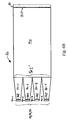
A first proposed approach consists in using LED arrays whose overall surface is
smaller or equal to that of the light valve. In this case the light is guided onto the
light valve by a single and simple light pipe, whose role also consists in making
uniform the light distribution as shown in Fig. 1. The light pipe, also called
integrator rod, can either be a solid glass or plastic rod or a hollow mirrored tube
e. g. with a rectangular cross section. For a good coupling efficiency, an air gap
is required between the LED array and the light pipe, and between the light pipe
and the light valve. To avoid that too much light escapes laterally, this air gap
should be kept as small as possible. The simplicity of the design is based on the
matching of the light pipe and the light valve cross sections. Thus the light valve
is uniformly illuminated by light coming out from the light pipe. The cross
section of the LED array has to be smaller or equal to the cross section of the
light valve.
Beside marginal losses produced by Fresnel reflection at the light pipe
extremities, all the light emitted by the LED array is directed onto the light valve.
At this point, the light has to go through the light valve and the projection optics
before reaching the projection screen. Both the light valve and the projection
optics have a limited angle of acceptance or aperture. This means that only the
light included within a given cone of acceptance is going to reach the screen, the
rest being lost.
The aperture of the projector is determined by the F/number of the projection
optics, typically F/3 (half cone angle of 10°) for reflective light valve and F/2
(half cone angle of 15°) for transmissive light valves. This means that at the light
valve plane, all the light which is not within the cone of acceptance is lost.
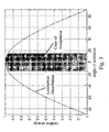
LEDs, without complementary optics, emit light vs. a Lambertian distribution.
When the light reaches the projection optics, only the proportion of light within
the cone of acceptance is going to reach the screen. As shown in Fig. 3, only
small part of the emitted energy (3,0% for F/3 and 6,7% for F/2) is included
within the acceptance cone.
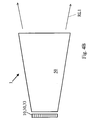
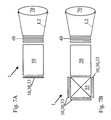
The optics between the LED array and the light valve can redirect the rays within
the cone of acceptance, increasing the efficiency of the device. This can be done
either, by using collimation micro-lenses in front of the LED array as shown in
Fig. 4A, or by using a pyramidal integration rod according to Fig. 4B. In both
cases however, the active emitting surface is considerably smaller than the light
valve surface. In other words, the efficiency of the illumination engine can be
improved by using collimation optics, but at the cost of the light throughput of
the LED array because of a diminution of the emitting surface.
Overall the limited (but improving) throughput of the Lambertian emitting LED
arrays limit their use to low lumen output projectors requiring, e. g. in rear-projection
TV.
Vertical cavity surface emitting lasers (VCSEL) have the interesting property that
they emit light within a cone of typically beam divergence of ±8° which is smaller
than the cone of acceptance of the projection optics. Therefore, beside the losses
of each individual optical element, all the energy emitted by a VCSEL array
would reach the screen. As shown in Fig. 2, the VCSEL array can have the exact
cross-section of the light valve. The intermediate optics, i. e. the integration rod,
is only used as light distribution uniformiser and has no collimation
functionality. The integration rod also eliminates any coherent property of the
VCSEL, i. e. speckle.
Laser diodes have astigmatic emission, i.e. they do not need to be collimated in
one axis (like VCSELs), but require collimation in the other axis. Asymmetric
light pipes are therefore used.
Figure 5 illustrates the architecture of a three-colour-path transmissive projector
based on solid state light sources either LED array of VCSEL array and/or
RCLED array. The imaging optics light valve and projection lens can be the same
as those of a high-pressure lamp projector. However, the illumination engine is
simplified and more compact, no fly-eye lens, no relay lenses are involved.
The architecture of a hybrid projector, using high-pressure lamp for the green
and blue channels and a solid state light source for the red channel, is
schematically shown in Fig. 6. The goal of this configuration is to boosts the
throughput of the red channel, which is relatively weak in standard HP lamp
projectors (limitation due to the emission spectrum of high-pressure lamps). It
should be noted that the more efficient visible solid state light source are
available in the red.
Solid state light sources can also be used in sequential colour projectors. The
advantage over HP lamp sequential projectors is that colour management can be
done directly at the source level, i. e. no colour filter for colour separation is
needed. The colour selection is made electronically by switching on and off the
different light sources.
Very compact architectures can be achieved when using back-lighting
illumination light pipes. The illumination light pipes have a similar design to
those used for the back-lighting of T-LCD displays, typically used in laptops an
cell phones. The light is guided inside the light pipe by total internal reflection
and is selectively out-coupled from the light pipe by scattering zones placed
along the light pipe surface. These compact projectors can be embedded into
portable devices such as UMTS cell phones, camcorders, palmtops, or the like.
What distinguish configurations of Figs. 6, 7 and 8 is the place available for the
sources, i. e. for the emission surface, and therefore the resulting lumen
throughput of the projector. The extremely reduced space available for the
sources in Fig. 8 configurations implies the use of a highly efficient light sources,
like VCSEL arrays and/or RCLED arrays.
Configurations based on reflective light valves can also be built around solid
state light sources. Nevertheless, the integration rod cannot be placed in close
contact with the light valve, as the light should escape through the projection
lens. In other words, some kind of beam splitter is needed in front of the light
valve. The uniform distribution of light coming out of the integration rod has to
be projected by some relay optics on the light valve. Basically all the standard
reflective projector configurations based on integration rods can be adapted in
order to use solid state light sources.
These reflective configurations are not as compact as the proposals based on
transmission light valves. On the other hand there is space to place some kind of
polarization recycler between the integration rod and the light valve. The same
remark applies to traditional transmission configurations which make use of
integration rod, relay optics and polarization recycler. They can also be adapted
in order to make use of solid state light sources.
When compared with traditional high pressure lamp projectors the invention
offers the following advantages:
- Better colour saturation and larger colour gamut
- Colour management at the source level
- no need of colour filters
- electronic sequential colour management
- possibility of dynamic contrast adjustment.
- Much increased lifetime of the source
- No infrared emission on the optical path (cold light source)
- possibility to use low cost plastic optics
- Possibility to improve the red channel of current three-colour-path
projectors.
When compared with other proposed LED projectors the invention offers the
following advantages:
- Simpler design based on integration rod in close contact with the source
panel and the light valve (no fly-eye lens, no relay optics)
- Optimised LED-to-light-valve coupling efficiency
- Use of directive emitting VCSELs, RCLEDs, or LDs for much increased
optical efficiency
- Ultra compact configurations based on back-lighting light pipes.
In the following, some further general and theoretical aspects of the inventive concept
and its realisations are given taking reference to figures 10 to 12:
One Aspect of the present invention and its embodiments is to solve the problem of
finding a configuration which maximizes the illumination of a surface using an array of
LEDs. Moreover, the illumination of the surface needs to be uniform and the direction of
the rays kept within a limited aperture. The aperture or the angle of acceptance is
determined by the numerical aperture of the imaging optics. The difficulty of the task
comes from the fact that the angle of acceptance is generally small when compared to the
large angular emission of the LEDs, having e.g. typically a Lambertian distribution.
An illuminated surface may be, for example, the probe plane of a microscope, or
the light valve plane of a projector. The imaging optics are in these cases the
microscope objective or the projector objective.
The constant improvement of the lumen output of light emitting diodes or LEDs
make them natural candidates to be used as illumination light sources for
automotive and building lighting. Other application like microscopy and
projection display are more demanding as the surface to illuminate is relatively
small, it has to be illuminated uniformly and within the angle of acceptance or
aperture of the optics. The light source may either be formed by a single LED, or
preferably by an LED array when the required brightness is high.
For LED arrays, it has been proposed to achieve the light collection using light
pipes or fibers. The uniformity is usually achieved using an integration rod. In
order to collimate the light within the aperture of the optics, an imaging optics is
used to image the exit surface of the rod onto the plane to illuminate.
Our inventive proposal consists of a simpler - therefore cheaper - and more
energy efficient approach, as the pyramid light pipes fulfill three functions of
light collection, light integration, and light collimation.
One problem of illumination devices using LEDs is the goal to illuminate a plane
uniformly with maximum light power and within a limited aperture of the optics.
In other words,
have to be achieved and are achieved by the present invention.
By using a single component from the solid state light source 30 or LED array 33
to the illuminated plane, the proposed approach minimizes the optical losses,
lowers the manufacturing costs, and simplifies the device assembly.
The problem which is illustrated in Fig. 10, consists of finding a configuration
which maximizes the illumination of a surface using an solid state light sources
or array 33 of LEDs 31. Moreover the illumination has to be uniform and the
direction of the rays kept within a limited aperture.
The illuminated surface S2 may be, for example, the probe plane of a microscope,
or the plane of a light valve 40 of a projector. The maximal aperture of the
illumination rays is then defined by the numerical aperture of the microscope
objective or the F-number of the projector objective 70.
The collimation optics has to fulfil three roles : light collector, light uniformizer,
light collimator. These functions can be fulfilled by the combination of different
types of elements.
The difficulty of the task stems inter alia from the non-directive radiation pattern
emitted by the LEDs 31, which is e.g. typically a Lambertian distribution. This
light needs to be redirected onto the limited surface to illuminate and within the
limited aperture of the optics.
Theoretical background
In the following, again reference is taken to figures 10 to 12.
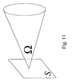
All illumination designs have to take into account the étendue theorem which
states that the étendue or optical extent along an optical system cannot be
reduced. For a given surface S the étendue E is defined by the surface S
multiplied by the solid angle Ω sustaining the light rays, i.e.
E = S·Ω,
according to Fig. 11 for Definition of the étendue E.
In the general system illustrated in Fig. 10, the maximal useful étendue E2 is
defined by the surface S2 to illuminate and the solid angle Ω2. For instance, if for
the étendue E1 of the source the relation E1>E2 holds, then part of the light is
lost.
The solid angle Ω
2 is function of the aperture of the optics and is given by the
equation
where ϕ
2 is the half angle of the cone of aperture.
The étendue E
1 of the LED array is defined as
where S
11 is the emission surface of each individual LED, N is the number of
LEDs in the array, and 2π is the solid angle of the hemisphere corresponding to
the Lambertian emission.
The étendue theorem states that the étendue along an optical system cannot be
reduced. Therefore, in order to achieve an optical system with a 100 %
collimation efficiency, the emission surface S, of the LED array cannot exceed
S
1max as is shown by the following relations
If for the surface of emission the relation S1≥S1max holds, part of the emitted light
will not reach the surface S2 within the aperture ϕ2, and will therefore be lost.
The problem is analysed by looking at what is the emitted cone or half-angle ϕ1
at the surface S1 which is within the aperture of the optics or half-angle ϕ2 at the
surface S1.
From the étendue theorem it follows that
is fulfilled. Therefore,
is also fulfilled.
The coupling efficiency ηc is defined as the ratio of the emitted energy W1 within
the cone defined by ϕ1, and the total energy W emitted by the source or surface
S1, i.e.:
η c = W 1 W .
In the case of a Lambertian light source with an emission angle γ=π/2, the
coupling efficiency becomes
The luminous flux W2 reaching the surface S2 within the aperture ϕ2 is
proportional to the emission surface S1 of the source and to the collimation
efficiency ηc,
W 2∝η c · S 1.
Three cases can be distinguished:
Proposed solution and features
Different solutions based on reflectors and/or refractive lenses have been
proposed for the collimation of LEDs. The drawback of these known approaches
is that it is difficult to collect 100% of the light in the desired direction. Moreover
the optics surrounding the LED is cumbersome, artificially increasing the
étendue of the source. In addition, further optics is needed to make the
illumination uniform, e.g. fly-eye lenses or an integration rod.
According to the present invention an approach based on - in particular
pyramidal shaped - integration rods is proposed. This approach fulfils the three
needed functions of
- collecting the light emitted by the LED array,
- collimating within the aperture of the optics, and
- homogenising the illumination.
The working principle of a pyramidal integration rod or PIR is illustrated in Fig.
5. The PIR has an entry surface S', an exit surface S", and length L. The PIR can
be an empty tube whose internal faces are mirrors, or a plain transparent
material - e.g. mineral glass, plastic or the like - of index n. For a plain PIR, the
rays are reflected on the surface by total internal reflection or TIR. As is
illustrated for two rays in Fig. 5, the angle with respect to the PIR surfaces
normal is smaller at the exit of the pipe than at its entrance. Given the étendue
theorem, the collimation is defined as
Ω"= S' S" · Ω'.
where Ω' is the solid angle of the ray before the PIR, and Ω" is the solid angle of
the ray after the PIR. The relations S">S' and Ω"<Ω' are fulfilled.
As for a normal integration rod, the rays are mixed within the rod. Two condition
have to be fulfilled in order to get an uniform distribution at the PIR exit surface:
The theoretical collimation efficiency ηc is achieved for L≥Lc. Above the length Lc
the collimation efficiency is constant. Lc is determined experimentally or by ray-tracing
simulation, in a case by case basis.
In problem described above, the PIR entry surface S' has to coincide with the
LED emission surface S1, and the PIR exit surface S" has to coincide with the
surface S2 to illuminate. As the LED array is constituted by a set small emission
surfaces S11, a micro PIR is placed in front of each LED. The light is then
collected by a bigger PIR or integration rod. The three systems illustrated in Fig.
6 are all equivalent, given the length of the PIR is long enough to complete the
collimation and the homogenisation.
Note that for a better coupling efficiency, an air gap is left between each LED and
the PIR surface.
Main advantageous features of the present invention are the usage of a single
optical element is used for light collection, light collimation, and light
homogenisation. By using a single component from the light source (LED array)
to the illuminated plane, the proposed approach minimizes the optical loses,
lowers the manufacturing costs, and simplifies the device assembly.
In the following the invention will be described in more detail taking reference to
the accompanying Figures.
- Figs. 1, 2
- illustrate a first preferred embodiment of the inventive illumination
arrangement.
- Fig. 3
- shows a graph which illustrates the relative emission of light as a
function of the direction angle of emission for a light emitting diode.
- Figs. 4A, B
- show details of further embodiments of the present invention.
- Figs. 5 - 9
- illustrate further embodiments of the present invention for multiple
colour applications.
- Figs. 10-12
- illustrate some of the theoretical background.
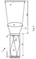
Fig. 1 demonstrates by means of a schematical and cross-sectional side view a
first preferred embodiment of the inventive illumination arrangement 1.
The embodiment of Fig. 1 consists of a light source device 10, which is built-up
by a solid state light source device 30. The solid state light source device 30 of
the embodiment of Fig. 1 consists of an array 33 of light emitting diodes 31. Said
array 33 is formed to have a light emitting area or light emitting aperture 30E
from which primary illumination light L1 is emitted to reach an incidence
aperture 501 of a light collecting, integrating and redirecting device 20 which may
consist as in the example of Fig. 1 of a light integrating device 50 and of a light
valve device 40, the former of which is in this case formed as an integration or
integrator rod 50 of a solid bulk material, for instance glass, plastic, or the like.
Rays of primary illumination light L1 entering said integrator rod 50 via said
light incidence aperture 50I are first of all refracted according to the Snell's law
of refraction and according to a refractive index of the material of the integrator
rod 50 being larger than the refraction index of the gap material of the gap G
between said integrator rod 50 and the light source device 10. During the
passage of the primary illumination light rays L1 within the material of the
integrator rod 50 said rays of light are reflected at the side walls or faces 50s of
the integrator rod 50. Finally, after a plurality or multiplicity of reflections at the
side walls 50s each of said received and multiply reflected rays of light of the
primary illumination light L1 exits from the integrator rod 50 via output aperture
50E and then enters the light valve 40 being situated in direct proximity to the
light output aperture 50E.
After exiting said integrator rod 50 via output aperture 50E, the light
distribution in the second gap G' between the integrator rod 50 and the light
valve 40 is more uniform than the light distribution at the first gap G between
the light source device and the integrator rod 50.
After receiving the redirected primary illumination light RL1 the respective rays
of light are allowed to pass through the light valve 40 in a controllable manner
and they leave the light valve 40 as secondary illumination light L2 to enter
certain projection optics 70, shown in Fig. 2, and then entering a display screen
80.
The gap G between the light source device 10 and the integrator rod 50 which is
shown in Figs. 1 and 2 is of particular importance as even in the case of an array
of light emitting diodes each of said diodes 31 only has a minor directive
emission capability because the light distribution or energy distribution of
emitting light waves obeys a Lambertian distribution as shown in Fig. 3. Fig 3
demonstrates this Lambertian distribution as a graph demonstrating the relative
energy of emitted light for a light emitting diode 31 as a function of the emission
angle. From the distribution of Fig. 3 it can be derived, that it is necessary to
keep the gap width of the gap G between the light source device 10 and the
integrator rod 50 as narrow as possible to increase the integral or the amount of
primary illumination light L1 entering the area of incidence or incidence aperture
501.
As can be seen from Fig. 2, the cones of acceptance of the integrator rod 50 and
the displaying optics 70 may be different. Therefore, it could be necessary to
adapt said cones of acceptance. This can be done alternatively by employing fly-eye-optics
as shown in Fig. 4A or more preferably by using an integrator rod 50,
having a pyramidal cross-section as shown in Fig. 4B.
Figs. 5 to 9 demonstrate different possibilities of combining solid state light
source devices 30 of different colours to obtain a multi-colour illumination
arrangement for a multi-colour projection system.
In Fig. 5 three different coloured solid state light source devices 30 having e. g.
light emitting diode arrays 33 are given, each of said solid state light source
devices 30and therefore each of said light emitting diode arrays 33 being
associated with an integrator rod 50 interposed between said solid state light
source device 30 and a light valve arrangement 40, so that for each of said light
source devices 30 of different colours an arrangement similar to that shown in
Fig. 1 is given.
To combine the three different colours of said three different solid light source
devices 30 a light mixing device 55 or colour cube 55 common for each of said
three arrangements is given being capable of receiving the respective secondary
illumination light L2, to mix them up, and to allow them to pass over to the
projection optics 70.
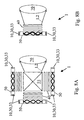
Fig. 6A to 6C show different embodiments of the light collecting, integrating and
redirecting unit or device 20 in the form of different integrator rod arrangements
each of which being adapted for an array 33 of LEDs 31 or 31-1 to 31-4 as a light
source device 10 and each of which being optically coupled to a light valve device
40.
In Fig. 6A the light collecting, integrating and redirecting unit or device 20 is
formed as a plurality of more or less similar or identical separated and parallely
arranged single pyramidal integrator rods 50-1 to 50-4 each of which being
uniquely assigned and coupled with its respective light entrance section 501 to a
given LED 31-1 to 31-4, respectively. The light entrances 501 are in each case
smaller than the respective light output sections 500 which are optically coupled
to the light entrance section 401 of a common light valve device 40.
In Fig. 6B the more or less similar or identical separated and parallely arranged
single pyramidal integrator rods 50-1 to 50-4 are optically coupled instead to the
light entrance section 501' of a common and integrator rod 50 the light exit 500
of which being optically coupled to the light entrance section 401 of a common
light valve device 40.
The common integrator rod 50 of the embodiment of fig. 6B has a uniform cross
section, whereas the cross section of common integrator rod 50 of the
embodiment of Fig. 6C is non-uniform and the respective integrator rod 50 is
formed pyramidal.
Figs. 7A and 7B demonstrate two different arrangements for realizing multiple
colour illumination arrangements for multiple colour projection systems which
differ from the embodiment of Fig. 5.
In the embodiment of Fig. 7A a solid state light source device 30 is employed as
said light source device 10 which has a LED-array 33, the members of which, i.
e. the distinct light emitting diodes 31, possessing different spectral emission
ranges, i. e. different colours. After the passage of the primary illumination light
L1 through the integrator rod 50 at the gap G' between the light valve 40 and the
integrator rod 50, the uniform light distribution and the uniform colour
distribution after passing the light valve 40 is then directed to the projection
optics 70.
In the case of the embodiment of Fig. 7B three different coloured solid state light
source devices 30, each of which being built-up by an array 33 of light emitting
diodes 31 have distinct spectral ranges or colours with respect to each other. The
primary illumination light L1 of each of said single solid state light source
devices 30 is directed to the light mixing device 55 which after mixing directs the
output light to the integrator rod 50 to obtain a secondary illumination light L2
at the gap G' between the light valve 40 and the integrator rod 50 having a
uniform illumination and colour distribution.
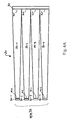
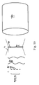
Figs. 8A and 8B demonstrate further examples of multiple colour illumination
devices. In these cases illumination light pipes 50 are used for redirecting and
making uniform received amounts of primary illumination light L1. In contrast to
the embodiments discussed above, where the incidence aperture 501 at which
primary illumination light L1 enters the distinct integrator rod 50 and the output
aperture 50E are disposed in parallel to each other, the incidence apertures 501
and output apertures 50E of the embodiments of Figs. 8A and 8B are
perpendicular to each other. Therefore, primary illumination light L1 emitted by
solid state light source devices 30 of the embodiments of Fig. 8A and 8B enters
the associated illumination light pipes 50 at their base faces, whereas the
redirected primary illumination light RL1 exits from said illumination light pipes
50 at side faces thereof.
A difference between the embodiments of Figs. 8A and 8B is that for obtaining a
multi-colour arrangement in Fig. 8A a plurality of single coloured solid state light
source devices 30 or LED-arrays 33 is necessary, whereas in the embodiment of
Fig. 8B multiple coloured solid state light source devices 30 or LED-arrays 33 are
provided.
Of course, in the embodiment of Fig. 8A according to the multiplicity of single-coloured
solid state light source devices 30 again a light mixing device 55 is
necessary.
The embodiment of Fig. 9 demonstrates an application of the embodiment of Fig.
7B, having intermediate optics 81, 82 for adapting the cones of acceptance
between the integrator rod 50 and the light valve 40. The intermediate optics 81,
82 consists of a lens arrangement 81 and a polarization beam splitter 82 which
in combination with each other transforms or maps the cone of acceptance of the
integrator rod 50, i. e. the geometry of the redirected primary illumination light
RL1, to the cone of acceptance of the light valve 40, which is in the embodiment
of Fig. 9 a reflective light valve 40 which allows the passage of secondary
illumination light L2 to the projection optics 70 upon reflection at the interface
of light valve 40.
Reference Symbols
- 1
- Illumination arrangement
- 10
- light source devive
- 20
- light collecting, integrating and redirecting device
- 30
- solid state light source device
- 30E
- light exit aperture, light output aperture
- 30I
- light incidence aperture, light entrance aperture
- 30O
- light exit aperture, light output aperture
- 31
- solid state light source, LED
- 31-1
- solid state light source, LED
- 31-2
- solid state light source, LED
- 31-3
- solid state light source, LED
- 31-4
- solid state light source, LED
- 32
- solid state light source
- 33
- array of solid state light sources
- 40
- light valve device, LCD panel
- 40E
- light exit aperture, light output aperture
- 40I
- light incidence aperture, light entrance aperture
- 40O
- light exit aperture, light output aperture
- 50
- light integrating device, integrator rod, light pipe
- 50E
- light exit aperture, light output aperture
- 50E'
- light exit aperture, light output aperture
- 50I
- light incidence aperture, light entrance aperture
- 50I'
- light incidence aperture, light entrance aperture
- 50O
- light exit aperture, light output aperture
- 50s
- side wall
- 50-1
- light integrating device, integrator rod, light pipe
- 50-2
- light integrating device, integrator rod, light pipe
- 50-3
- light integrating device, integrator rod, light pipe
- 50-4
- light integrating device, integrator rod, light pipe
- 55
- light mixing device, beam splitter device, colour cube device
- 60
- display optics
- 70
- projection optics
- 80
- display, display screen
- 81
- intermediate optics, lens arrangement
- 82
- intermediate optics, polarization beam splitter
- G
- gap structure
- G'
- gap structure
- L1
- primary illumination light
- L2
- secondary illumination light
- RL1
- redirected primary illumination light