EP1414378B1 - Intragastric device for treating obesity - Google Patents
Intragastric device for treating obesity Download PDFInfo
- Publication number
- EP1414378B1 EP1414378B1 EP02734462A EP02734462A EP1414378B1 EP 1414378 B1 EP1414378 B1 EP 1414378B1 EP 02734462 A EP02734462 A EP 02734462A EP 02734462 A EP02734462 A EP 02734462A EP 1414378 B1 EP1414378 B1 EP 1414378B1
- Authority
- EP
- European Patent Office
- Prior art keywords
- intragastric device
- intragastric
- configuration
- digestive
- bundles
- Prior art date
- Legal status (The legal status is an assumption and is not a legal conclusion. Google has not performed a legal analysis and makes no representation as to the accuracy of the status listed.)
- Expired - Lifetime
Links
Images


Classifications
-
- A—HUMAN NECESSITIES
- A61—MEDICAL OR VETERINARY SCIENCE; HYGIENE
- A61F—FILTERS IMPLANTABLE INTO BLOOD VESSELS; PROSTHESES; DEVICES PROVIDING PATENCY TO, OR PREVENTING COLLAPSING OF, TUBULAR STRUCTURES OF THE BODY, e.g. STENTS; ORTHOPAEDIC, NURSING OR CONTRACEPTIVE DEVICES; FOMENTATION; TREATMENT OR PROTECTION OF EYES OR EARS; BANDAGES, DRESSINGS OR ABSORBENT PADS; FIRST-AID KITS
- A61F5/00—Orthopaedic methods or devices for non-surgical treatment of bones or joints; Nursing devices; Anti-rape devices
- A61F5/0003—Apparatus for the treatment of obesity; Anti-eating devices
- A61F5/0013—Implantable devices or invasive measures
- A61F5/0036—Intragastrical devices
-
- A—HUMAN NECESSITIES
- A61—MEDICAL OR VETERINARY SCIENCE; HYGIENE
- A61F—FILTERS IMPLANTABLE INTO BLOOD VESSELS; PROSTHESES; DEVICES PROVIDING PATENCY TO, OR PREVENTING COLLAPSING OF, TUBULAR STRUCTURES OF THE BODY, e.g. STENTS; ORTHOPAEDIC, NURSING OR CONTRACEPTIVE DEVICES; FOMENTATION; TREATMENT OR PROTECTION OF EYES OR EARS; BANDAGES, DRESSINGS OR ABSORBENT PADS; FIRST-AID KITS
- A61F5/00—Orthopaedic methods or devices for non-surgical treatment of bones or joints; Nursing devices; Anti-rape devices
- A61F5/0003—Apparatus for the treatment of obesity; Anti-eating devices
Definitions
- This invention relates to medical devices, and more particularly to obesity treatment devices that can be placed in the stomach of a patient to reduce the size of the stomach reservoir.
- balloons In the early 1980s, physicians began to experiment with the placement of intragastric balloons to reduce the size of the stomach reservoir, and consequently its capacity for food. Once deployed in the stomach, the balloon helps to trigger a sensation of fullness and a decreased feeling of hunger.
- These balloons are typically cylindrical or pear-shaped, generally range in size from 200-500 ml or more, are made of an elastomer such as silicone, polyurethane, or latex, and are filled with air, water, or saline. While some studies demonstrated modest weight loss, the effects of these balloons often diminished after three or four weeks, possibly due to the gradual distension of the stomach or the fact that the body adjusted to the presence of the balloon.
- Other balloons include a tube exiting the nasal passage that allows the balloon to be periodically deflated and re-insufflated to better simulate normal food intake. However, the disadvantages of having a inflation tube exiting the nose are obvious.
- intragastric member that provides the potential weight loss benefits of a bezoar or intragastric balloon without the associated complications.
- a device should be well-tolerated by the patient, effective over a long period of time, sizable for individual anatomies, and easy to place and retrieve.
- an intragastric device for the treatment of obesity comprising a digestive-resistant material that is expandable from a first configuration to a second configuration, the first configuration being sufficiently small to permit introduction of the intragastric device into a gastric lumen of a mammal, the second configuration being sufficiently large to prevent the intragastric device from passing through the mammal's pylorus, wherein the intragastric device is configured to function as an artificial bezoar.
- US-A-4 315 509 shows a balloon-like tube, which, however, is not inserted into the stomach, but into the beginning of the small intestine, in this way treatment of the food in the intestine is reduced and thus the caloric intake.
- US-A-4 607 618 already shows a balloon-like device which can be inserted into the stomach and works like an artificial bezoar. However, this device is follow and thus there is a considerable risk of bursting or puncturing the device.
- the obesity treatment apparatus 10 of the present invention depicted in FIGS. 1-25 comprises one or more intragastric members 11, each comprising one or more digestive-resistant or indigestible member 12 sized and configured such that the intragastric member 11 can be placed into the stomach of a mammalian patient and reside therein, and being generally unable to pass through the pylorus.
- the terms digestive-resistant and indigestible are intended to mean that the material used is not subject to the degrative effects of stomach acid and enzymes, or the general environment found within the gastric system over an extended period of time, therefore allowing the device to remain intact for the intended life of the device. This does not necessarily mean that the material cannot be degraded over time; however, one skilled in medical arts and gastrological devices would readily appreciate the range of material that would be suitable for use as a long-term intragastric member.
- plastics have suitable properties, including selected polyesters, polyurethanes, polyethylenes, polyamides, silicone, or other possible materials.
- Mammalian hair has been found to form natural bezoars, and thus, is also a possible material.
- some materials, such as certain polyamides have been found to expand over time, which can be an undesirable property.
- Most other natural materials are generally much less resistant to acids and enzymes, and would therefore typically require treatment or combination with resistant materials to function long term, unless a shorter-term placement is intended or desired.
- the digestive-resistant or indigestible member 12 comprises a low density polyethylene having a thickness of about 40-50 microns.
- Fluorinated ethylene propylene, ethylene vinyl acetate copolymer, nylon, or types of polymers that are biocompatible and to which food will generally not adhere may also be utilized.
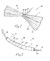
- FIG. 1 depicts a single intragastric member 11 in which the digestive-resistant members 12 include a plurality of elongate plastic strips 30 that are secured together in the middle by a retaining element 34, such as a nylon thread.
- the thread can be elongated to serve as a coupling mechanism 26, such as a tether 27.
- the number of digestive-resistant members 12 or strips 30 used to form the intragastric member 11 depends on the material used, their length and width, and how many intragastric members 11 comprise a set or grouping. The optimal length of the intragastric member 11 is determined by considering these same factors, as well by what is determined through experimentation to work best.
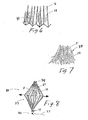
- FIGS. 6-7 depict an alternative digestive-resistant member 12.
- the strips 30 of FIG. 1 are replaced by digestive-resistant member 12 comprising a folded or pleated sheet 31 of plastic or other material.
- digestive-resistant member 12 comprising a folded or pleated sheet 31 of plastic or other material.
- Either a single sheet 31 or multiple sheets can be used to form the intragastric member 11 of this embodiment.
- FIG. 7 depicts an intragastric member 11 in which the digestive-resistant members 12 comprise a plurality of elongated fibers or hairs 32, typically made of polymer or other synthetic material.
- FIG. 8 depicts an expandable device 33 that comprises a retaining element 34 at one end to secure the digestive-resistant members 12, which in this embodiment are typically made of a material having a certain degree of stiffness. The other end is secured by a second, slidable retaining element 41 that is disposed over a tether 27 attached to the first retaining member 34.
- the intragastric member 11 is deployed in an elongated configuration with the retaining elements 34, 41 located near their maximum possible difference apart.
- the slidable retaining element 41 is urged along the tether 27 and toward the first retaining element 34 by using a tube, probe, or other device, until the digestive-resistant members 12 have bowed outward, thus increasing the overall dimensions and volume of the device.
- the slidable retaining element 41 continues to grip the tether 27 after the urging mechanism is removed, retaining the increased dimensions of the intragastric member 11, until further manipulation is needed to reduce its diameter for removal from the patient.
- FIGS. 2-4 depict one such delivery system 44 in which first and second intragastric members 24, 25 are mounted over a plastic overtube 18 and secured by a series of suture ties 43, such as cotton thread.
- a wire guide 19 is typically used in the procedure, and is placed through the passageway 52 of the overtube 18.
- the overtube 18 includes a plurality of apertures 21, a pair of which (e.g., apertures 22 and 23) are distributed approximately every 2 cm along the distal portion of the overtube 18.
- the suture tie is pulled through the first aperture 22 using a device 42 such as a loop, hook, snare, etc. It is fed through a releasing mechanism 20, such as the illustrative wire loop, and then pulled through the opposite aperture 23.
- the intragastric members 24, 25 are then placed on the overtube 18, and the suture ties 43 are secured, thereby constraining the intragastric members into a first configuration 14 for delivery.
- the releasing mechanism 20 is pulled back through the overtube 18, thereby severing the suture ties 43 one by one and releasing the intragastric members 11 into the gastric lumen where they can assume a second configuration 10 (see FIG. 1 ) that is sufficiently voluminous such that they cannot pass from the stomach.
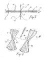
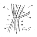
- FIG. 4 shows the two deployed intragastric members 24, 25 that each have a coupling mechanism 26 (tether 27) attached about them such that they can be drawn together as depicted in FIG. 5 .
- a push member 29, such as a corrugated metal tube is placed into gastric lumen by using an endoscope, and is guided over the tethers 27 to urge a securing element 28, such as a rubber patch, tightly against the two intragastric members 24, 25.
- the tethers 27 can then be cut, allowing the grouping 45 to float free within the stomach.
- This method can also be used to join additional intragastric members 11 to form a larger grouping 45.
- the illustrative delivery system 44 of FIG. 2 can be used to deliver any practical number of intragastric members 11, which can then be joined in the manner described above, or they can be delivered singly or in pairs, and then grouped together after all of the intragastric members 11 have been placed. -
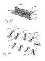
- FIGS. 9-11 depict intragastric members 11 that are delivered into the gastric lumen within an outer member 35, such as a sheath, tube, package, wrapping, etc., and subsequently released.
- FIG. 9 depicts a delivery system 44 in which the intragastric member 11 (or multiple devices) is preloaded into an outer tube or introducer, then deployed therefrom by being pushed out by using a pusher member (not shown). The intragastric member 11 is shown twisted to aid in loading and deployment.
- FIG. 10 depicts a delivery system 44 in which the intragastric member is loaded over a tube 18 (as in FIG. 2 ), but is secured by an outer member 35 comprising a splittable sheath 37 or sleeve made of a thin plastic material.
- the releasing mechanism 20 comprises a nylon thread or wire that is looped under and over the sheath 37, such that it can be withdrawn to tear through the thin material of the sheath 37 to release the intragastric member(s) 11 mounted on the tube 18.
- the releasing mechanism of FIG. 10 feeds into an aperture 21 and passageway 52 of the tube 18, where it extends to the proximal end of the apparatus 10.
- Other types of splittable sheaths 37 can also be used, such as the COOK® PEEL-AWAY Introducer Sheath.
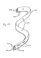
- FIG. 11 depicts an intragastric member 11 that includes an outer member 35 comprising a dissolvable enclosure 38.
- the material such as cellulose, gelatin, or some other dissolvable or rapidly degrading synthetic or biomaterial material, allows the intragastric member 11 to be deployed in the first configuration 14 into the stomach, where it expands into the second configuration 15 (see, e.g., FIG. 1 ) once the outer enclosure 38 has dissolved or degraded away.
- the embodiment of FIG. 11 can be delivered with or without a catheter-based delivery system 44, or swallowed by the patient, depending on the outer dimensions of the apparatus 10.
- FIG. 12 also depicts a method of delivering the apparatus 10 of the present invention without a catheter or tube 18. It has been found that the intragastric members 11 can be pulled into the gastric lumen using an endoscope 39 and endoscopic instrument 40, such as a forceps, basket, snare, etc. This technique can be employed to pull groupings 45 (see, e.g., FIG. 4 ) of intragastric members 11 into the gastric lumen, as long as the alimentary tract is sufficiently wide to accommodate the grouping 45.
- endoscope 39 and endoscopic instrument 40 such as a forceps, basket, snare, etc.
- This technique can be employed to pull groupings 45 (see, e.g., FIG. 4 ) of intragastric members 11 into the gastric lumen, as long as the alimentary tract is sufficiently wide to accommodate the grouping 45.
- FIGS. 13-14 depict a grouping 45 of four intragastric members 24, 25, 49, 50 that are pre-coupled to one another by a coupling mechanism 26 prior to introduction into the gastric lumen.
- a coupling mechanism 26 prior to introduction into the gastric lumen.
- the coupling mechanism 26 comprises a grouping mechanism 46, such as a nylon thread (e.g., standard nylon fishing line), that is wrapped around the grouping 45 to pull them into close contact with one another.
- the grouping is released by severing the line comprising the grouping mechanism 46 and the intragastric members 24, 25, 49, 50 are removed one at time using a retrieval device such as that shown in FIG. 12 .
- the first coupling component 47 comprises a curved polymer piece which is traversed by the line 46 in such a manner that the line 46 can be readily visualized under the scope, thereby providing a place to grasp and/or cut the line with an instrument extending from the endoscope.
- the second coupling component 48 comprises a fishing line swivel, which being metal, can be readily visualized, as well as providing a hard surface against which a cutting instrument can be applied to sever the line 46, especially if the line has proved difficult to cut using other methods. It also provides an easily accessible point on the apparatus 10 which can be grabbed with a forceps or other device.
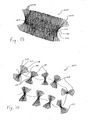
- FIG. 15 depicts another embodiment of an intragastric member 100 of the present invention.
- the intragastric member 100 comprises a single strip of high-density polyethylene 102 that has been folded and bundled to form eighty-nine (89) loops 104 in the general shape of a butterfly.
- the single strip of high-density polyethylene 102 of the embodiment is formed from a tube of material having a wall thickness of 7.5 microns and a perimeter of 6 cm that has been sliced in half. Each half of the material is then folded to form a strip 102 having two walls 106, 108, wherein each wall 106, 108 has a width of 1.5 cm.
- the strip 102 could comprise a different number of walls 106, 108, have a different width and thickness, or be formed from a tube of material.
- each loop 104 is 40 cm in length. Accordingly, the intragastric member 100 is formed from single strip 102 having a total length of approximately 35.6 m.
- the intragastric member 100 is bundled by passing a nylon thread 110 through an aperture 112 in the strip 102 at the center of the each loop 104.
- the apertures 112 are formed in each wall 106, 108 of the strip 102, and are spaced so that loops 104 are formed 40 cm in length when adjacent apertures 112 are pulled together to form the intragastric member 100 shown in FIG. 15 .
- the apertures 112 are located every 40 cm along the length of the strip 102.
- the embodiment of the intragastric member 100 shown in FIG. 15 may be too large for delivery or insertion into the gastric lumen while in its bundled, final configuration. Accordingly, the intragastric member 100 is preferably inserted into the gastric lumen is stages. For example, and as shown in FIG. 16 , the intragastric member 100 is separated into nine (9) separate bundles 114, each of which comprise approximately ten (10) loops 104 of the strip 102. The loops 104 of each separate bundle 114 are temporarily grouped or held together by a twist tie 116 or similar device. Grouping the separate bundles 114 in this manner improves the handling of the material and prevents the strip 102 from becoming tangled or contaminated.
- the separate bundles 114 of the intragastric member 100 are inserted into the gastric lumen one at a time by using a wire guide 118 such as a Savary-Gilliard TM wire guide, manufactured by Wilson-Cook Medical Inc., Winston-Salem, North Carolina.
- the wire guide 118 comprises a central opening through which the nylon thread 110 passes.
- the end of the nylon thread 110 is connected to or tied around a small piece of nylon tubing 120 that is sized so as to not pass through the apertures 112 in the strip 102.
- the nylon tubing 120 Prior to the insertion procedure, the nylon tubing 120 is placed near the distal (forward or insertion) end of the wire guide 118 so as to prevent the strip 102 of the first bundle 114 from sliding off the end of the wire guide 118.
- the first bundle 114 is threaded over the proximal (rearward) end by passing the apertures 112 over the wire guide 118.
- a plastic tube 122 is then positioned over the proximal end of the wire guide 118, and slid towards the distal end of the wire guide 118 so as to push the folds 104 of the first bundle against the nylon tubing 120.
- This procedure is then repeated by threading subsequent bundles 114 over the wire guide 118 and pushing them against the previously inserted bundles 114 until all of the bundles 114 have been inserted into the gastric lumen.
- the bundles 114 are then secured together by pushing a small rubber stopper or similar device 124 (see FIG.
- the nylon thread 110 is typically cut so as to release the folds 104.
- One end of the strip 102 is then grasped by an endoscopic or similar device and pulled out of the patient.
- FIG. 19 depicts yet another embodiment of an intragastric member 200 of the present invention.
- the intragastric member 200 comprises a double strip of low-density polyethylene 202 that has been folded and bundled to form approximately forty-five (45) loops 204 in the general shape of a butterfly.
- the double strip of low-density polyethylene 202 of this embodiment comprises a pair of strips 202 each having two walls 206, 208, wherein each wall 206, 208 has a width of 15 mm and thickness in the range of 40-50 microns.
- each loop 204 is 20 cm in length. Accordingly, the intragastric member 200 is formed from a double strip 202 of material having a total length of approximately 18 m (i.e., each strip 202 has a total length of approximately 18 m). A double strip 202 having longer or shorter lengths may also be used depending on the desired size and mass of the intragastric member 200.
- the intragastric member 200 is bundled by passing a nylon thread 210 through an aperture 212 in each strip 202 at the center of the each loop 204.
- the apertures 212 are formed in each wall 206, 208 of each strip 202, and are spaced so that loops 204 are formed 20 cm in length when adjacent apertures 212 are pulled together to form the intragastric member 200 shown in FIG. 19 .
- the apertures 212 are located every 20 cm along the length of the strip 202.
- apertures 212 have a diameter of approximately 3.5 mm.
- the embodiment of the intragastric member 200 shown in FIG. 19 may be too large for delivery or insertion into the gastric lumen while in its bundled, final configuration. Accordingly, the intragastric member 200 is preferably inserted into the gastric lumen is stages. For example, and as shown in FIG. 20 , the intragastric member 200 is separated into nine (9) separate bundles 214, each of which comprise approximately five (5) loops 204 of the strip 202. The loops 204 of each separate bundle 214 are grouped or held together by a breakable tie 216, made of cotton thread, or similar device. As will be explained below, grouping the separate bundles 214 in this manner improves the handling of the material and prevents the strips 202 from becoming tangled or contaminated during the insertion thereof.
- the separate bundles 214 of the intragastric member 200 are inserted into the gastric lumen one at a time by using a wire guide 218 such as a Savary-Gilliard TM wire guide, manufactured by Wilson-Cook Medical Inc., Winston-Salem, North Carolina.
- the wire guide 218 comprises a central opening through which the nylon thread 210 passes.
- the end of the nylon thread 210 is connected to or tied around a small nylon disc 220 that is sized so as to not pass through the apertures 212 in the strips 202.
- the nylon disc 220 Prior to the insertion procedure, the nylon disc 220 is placed near the distal (forward or insertion) end of the wire guide 218 so as to prevent the strips 202 of the first bundle 214 from sliding off the end of the wire guide 218.
- the first bundle 214 is threaded over the proximal (rearward) end by passing the apertures 212 over the wire guide 218.
- a pusher tube 222 which may be plastic, metal or some other suitable material, is then positioned over the proximal end of the wire guide 218, and slid towards the distal end of the wire guide 218 so as to push the folds 204 of the first bundle 214, which remain bundled by tie 216, against the nylon disc 220.
- one or more of the apertures 212 in each bundle 214 have an increased diameter that is sufficient to allow one more folds 204 to slide over the outside of the pusher tube 222. This permits the portion of the strips 202 connected between adjacent bundles 214 to be guided (extended) along the wire guide 218 without interfering with the deployment of each bundle 214.
- those apertures 212 having an increased diameter are approximately 9-10 mm in diameter.
- This procedure is then repeated by threading subsequent bundles 214 over the wire guide 218 and pushing them against the previously inserted bundles 214 until all of the bundles 214 have been inserted into the gastric lumen.
- the bundles 214 are then secured together by pushing a small rubber stopper or similar device 224 (see FIG. 19 ) along the wire guide 218 so as to press against the last bundle 214 to be inserted.
- the wire guide 218 is then withdrawn so as to leave the nylon thread 210 extending through the apertures 212 of all of the bundles 214.
- the nylon thread 210 is then tied or otherwise secured to the stopper 224 so as to form a complete intragastric member 200 as shown in FIG. 19 .
- the nylon thread 210 is typically cut so as to allow the intragastric member 200 to separate in separate bundles (see FIG. 20 ).
- the separate bundles 214 which remain connected to each other by strips 202, can then be removed one at a time.
- breakable ties 216 may be severed to release the folds 204 of one or more of the bundles 216.
- visual markers 226, such as colored tubing, are sutured to the side of the strips 202 of the first or last fold 204 on either side of the aperture 212. These markers 226 assist the physician in locating the nylon thread 210, which may be difficult to identify after the device has resided within the gastric lumen for an extended period of time. Once the nylon thread 210 is cut, one end of the pair of strips 202, or one of the bundles 216, is then grasped by an endoscopic or similar device and pulled out of the patient.
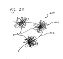
- FIG. 23 depicts yet another embodiment of an intragastric member 400 of the present invention.
- the intragastric member 400 comprises nylon thread 402 that has been tied into a series of nylon balls 404.
- the nylon balls 404 are inserted into the gastric lumen separately and then connected together to form a single, larger mass of nylon thread (not shown).
- the intragastric member 300 could be deployed by extending the strip 302 along a nylon thread 304 that has been formed into a loop 306.
- a locking device 310 such as plastic cone (shown in detail in FIG. 25 ) is pushed over both strands of the nylon thread 304 so as to close the loop 306.
- the strip 302 is compressed so as to form an intragastric member 300 having a configuration similar to that shown in FIGS. 15 and 19 .
- Knots 312 are included along the nylon thread 304 to provide a ratcheting action with the locking device 310. After the intragastric member 300 has been deployed inside the gastric lumen, then the portion of the nylon thread 304 extending beyond the locking device 310 can be severed with an endoscopic scissors and removed.
- the strip 302 can be compressed by sliding a tube (not shown) along one or both halves of the loop 306.
- the intragastric member 300 can be inserted in bundles (see FIGS. 16 and 20 ), as opposed to the insertion of a single strip 302 of material (as described above).
- An anchor stent could be utilized to temporarily secure the end of the nylon thread 304 (or the end 308 of the loop 306) inside the gastric lumen during the insertion procedure.
- an anchor stent enclosing a portion of the nylon thread 304 would be inserted into the pylorus and lodged therein.
- One end of the nylon thread 304 (or loop 306) enclosed within the anchor stent is then removed therefrom and pulled out of the subject.
- the other end of the nylon thread 304 (or loop 306) remains attached to the anchor stent.
- the intragastric device 300 can then be inserted into the gastric lumen by pushing or sliding the strip 302 (or bundles) down the nylon thread 304 (or loop 306), the end of which remains secured within the gastric lumen by the anchor stent. Once the insertion procedure is removed, then the anchor stent and any excess nylon thread 304 is removed.
- experimental testing of the present invention has been conducted on mammals.
- an embodiment of an intragastric member similar to the embodiment shown in FIGS. 19-21 was inserted into the gastric lumens of a group of ten (10) pigs for a period of 49 days. No deaths or major complications were observed in any of the test subjects.
- the initial weight for the test subjects was measured to be in the range of 25.0 to 31.2 kg, with an average weight of 27.8 kg.
- the weight of the test subjects was measured to be in the range of 29.5 to 39.0 kg, with an average weight of 34.5 kg.
- the anticipated weight for the test subjects at the end of the testing period, in view of the normal and expected growth for these animals, was 57 kg. Accordingly, the test subjects gained an average weight that was significantly less than the weight gain observed in similar animals without the intragastric member.
Abstract
Description
- This invention relates to medical devices, and more particularly to obesity treatment devices that can be placed in the stomach of a patient to reduce the size of the stomach reservoir.
- It is well known that obesity is a very difficult condition to treat. Methods of treatment are varied, and include drugs, behavior therapy, and physical exercise, or often a combinational approach involving two or more of these methods. Unfortunately, results are seldom long term, with many patients eventually returning to their original weight over time. For that reason, obesity, particularly morbid obesity, is often considered an incurable condition. More invasive approaches have been available which have yielded good results in many patients. These include surgical options such as bypass operations or gastroplasty. However, these procedures carry high risks, and are therefore not appropriate for most patients.
- In the early 1980s, physicians began to experiment with the placement of intragastric balloons to reduce the size of the stomach reservoir, and consequently its capacity for food. Once deployed in the stomach, the balloon helps to trigger a sensation of fullness and a decreased feeling of hunger. These balloons are typically cylindrical or pear-shaped, generally range in size from 200-500 ml or more, are made of an elastomer such as silicone, polyurethane, or latex, and are filled with air, water, or saline. While some studies demonstrated modest weight loss, the effects of these balloons often diminished after three or four weeks, possibly due to the gradual distension of the stomach or the fact that the body adjusted to the presence of the balloon. Other balloons include a tube exiting the nasal passage that allows the balloon to be periodically deflated and re-insufflated to better simulate normal food intake. However, the disadvantages of having a inflation tube exiting the nose are obvious.
- The experience with balloons as a method of treating obesity has provided uncertain results, and has been frequently disappointing. Some trials failed to show significant weight loss over a placebo, or were ineffective unless the balloon placement procedure was combined with a low-calorie diet. Complications have also been observed, such as gastric ulcers, especially with use of fluid-filled balloons, and small bowel obstructions caused by deflated balloons. In addition, there have been documented instances of the balloon blocking off or lodging in the opening to the duodenum, wherein the balloon may act like a ball valve to prevent the stomach contents from emptying into the intestines.
- Unrelated to the above-discussed methods for treating obesity, it has been observed that the ingestion of certain indigestible matter, such as fibers, hair, fuzzy materials, etc., can collect in the stomach over time, and eventually form a mass called a bezoar. In some patients, particularly children and the mentally handicapped, bezoars often result from the ingestion of plastic or synthetic materials. In many cases, bezoars can cause indigestion, stomach upset, or vomiting, especially if allowed to grow sufficiently large. It has also been documented that certain individuals having bezoars are subject to weight loss, presumably due to the decrease in the size of the stomach reservoir. Although bezoars may be removed endoscopically, especially in conjunction with a device known as a bezotome or bezotriptor, they, particularly larger ones, often require surgery.
- What is needed is a intragastric member that provides the potential weight loss benefits of a bezoar or intragastric balloon without the associated complications. Ideally, such a device should be well-tolerated by the patient, effective over a long period of time, sizable for individual anatomies, and easy to place and retrieve.
- The nearest state of the art in this field of technology is
US-A-5 868 141 . This document already discloses an intragastric device for the treatment of obesity, the intragastric device comprising a digestive-resistant material that is expandable from a first configuration to a second configuration, the first configuration being sufficiently small to permit introduction of the intragastric device into a gastric lumen of a mammal, the second configuration being sufficiently large to prevent the intragastric device from passing through the mammal's pylorus, wherein the intragastric device is configured to function as an artificial bezoar. - This state of the art, however, has the obvious disadvantage that the "artificial bezoar" only consists of a tripod-like structure with very thin arms. Thus, this device is not as effective as a real bezoar, which indeed takes away a part of the stomach's volume. The device according to the state of the art can nevertheless be filled with food and thus this device according to the state of the art does not effectively reduce the volume of the stomach.
-
US-A-4 315 509 shows a balloon-like tube, which, however, is not inserted into the stomach, but into the beginning of the small intestine, in this way treatment of the food in the intestine is reduced and thus the caloric intake. - This is, however; a totally different approach to this problem and it is of course rather difficult to apply such a device in the small intestine.
- Further,
US-A-4 607 618 already shows a balloon-like device which can be inserted into the stomach and works like an artificial bezoar. However, this device is follow and thus there is a considerable risk of bursting or puncturing the device. - It is thus the object of the present invention to provide such an endoscopic stomach insert, which can be as easily placed and removed from the stomach as the device of
US-A-5 868 141 and avoids the problems of a hollow balloon as inUS-A-4 607 618 , and nevertheless has the same efficiency as an artificial bezoar as the device ofUS-A-4 607 618 . - According to the invention, this problem is solved by an intragastric device with the features of
claim 1. - The sub-claims disclose favourable further developments of this device.
- These and other advantages, as well as the invention itself, will become apparent in the details of construction and operation as more fully described below. Moreover, it should be appreciated that several aspects of the invention can be used with other types of intragastric devices or procedures used for the treatment of obesity.
- Several embodiments of the present invention will now be described by way of example with reference to the accompanying drawings, in which:
-
FIG. 1 depicts a pictorial view of an intragastric member of the present invention; -
FIG. 2 depicts a pictorial view of the embodiment ofFIG. 1 with a delivery system; -
FIG. 3 depicts a sectional view of the delivery system ofFIG. 2 ; -
FIGS. 4-5 depicts a pictorial view of a pair of intragastric members of the present invention prior to, and after being coupled together; -
FIGS. 6-7 depict detail views of different embodiments of indigestible members of intragastric members of the present invention; -
FIG. 8 depicts a partially sectioned side view of an expandable intragastric member of the present invention; -
FIG. 9 depicts a pictorial view of an intragastric member of the present invention being delivered from an outer catheter; -
FIG. 10 depicts a pictorial view of an intragastric member of the present invention that includes a splittable outer sheath; -
FIG. 11 depicts a side view of an intragastric member of the present invention encased in a dissolvable outer package; -
FIG. 12 depicts a pictorial view of an intragastric member of the present invention being manipulated by a endoscopic device; -
FIG. 13 depicts a set of intragastric members of the present invention bundled together by a coupling mechanism; -
FIG. 14 depicts a schematic cross-sectional view taken along line 13-13 ofFIG. 13 ; -
FIG. 15 depicts a pictorial view of another embodiment of an intragastric member of the present invention; -
FIG. 16 depicts a pictorial view of the embodiment ofFIG. 15 separated into separate bundles and ready for insertion into the gastric lumen; -
FIG. 17 depicts a portion of the strip material that is used to form the embodiment ofFIG. 15 ; -
FIG. 18 depicts the insertion of the separate bundles ofFIG. 16 being inserted into the gastric lumen -
FIG. 19 depicts a pictorial view of yet another embodiment of an intragastric member of the present invention; -
FIG. 20 depicts a pictorial view of the embodiment ofFIG. 19 separated into separate bundles and ready for insertion into the gastric lumen; -
FIG. 21 depicts a portion of the strip material that is used to form the embodiment ofFIG. 19 ; -
FIG. 22 depicts the insertion of the separate bundles ofFIG. 20 being nserted into the gastric lumen; -
FIG. 23 depicts a pictorial view of yet another embodiment of an intragastric member of the present invention; and -
FIGS. 24 and 25 depict an alternative method of inserting of an intragastric member of the present invention into the gastric lumen. - The
obesity treatment apparatus 10 of the present invention depicted inFIGS. 1-25 comprises one or more intragastric members 11, each comprising one or more digestive-resistant orindigestible member 12 sized and configured such that the intragastric member 11 can be placed into the stomach of a mammalian patient and reside therein, and being generally unable to pass through the pylorus. As used herein, the terms digestive-resistant and indigestible are intended to mean that the material used is not subject to the degrative effects of stomach acid and enzymes, or the general environment found within the gastric system over an extended period of time, therefore allowing the device to remain intact for the intended life of the device. This does not necessarily mean that the material cannot be degraded over time; however, one skilled in medical arts and gastrological devices would readily appreciate the range of material that would be suitable for use as a long-term intragastric member. - Many well-known plastics have suitable properties, including selected polyesters, polyurethanes, polyethylenes, polyamides, silicone, or other possible materials. Mammalian hair has been found to form natural bezoars, and thus, is also a possible material. However, some materials, such as certain polyamides, have been found to expand over time, which can be an undesirable property. Most other natural materials are generally much less resistant to acids and enzymes, and would therefore typically require treatment or combination with resistant materials to function long term, unless a shorter-term placement is intended or desired.
- In the preferred embodiments, the digestive-resistant or
indigestible member 12 comprises a low density polyethylene having a thickness of about 40-50 microns. Fluorinated ethylene propylene, ethylene vinyl acetate copolymer, nylon, or types of polymers that are biocompatible and to which food will generally not adhere may also be utilized. -
FIG. 1 depicts a single intragastric member 11 in which the digestive-resistant members 12 include a plurality of elongateplastic strips 30 that are secured together in the middle by a retainingelement 34, such as a nylon thread. The thread can be elongated to serve as acoupling mechanism 26, such as atether 27. The number of digestive-resistant members 12 or strips 30 used to form the intragastric member 11 depends on the material used, their length and width, and how many intragastric members 11 comprise a set or grouping. The optimal length of the intragastric member 11 is determined by considering these same factors, as well by what is determined through experimentation to work best. - Feasibility studies have been primarily limited to placement in pigs with both 8 cm and 16 cm intragastric members being used, both having a total volume of about 40 ml when placed in the stomach of the animal. Although the experiments were designed to establish the safety of the device, significant weight loss was nevertheless observed in the test animals. Although no gastric ulcers were found in animals with polyester intragastric members, there was a 20% incidence of gastric ulcers in animals having polyamide devices.
- Results from human trials may lead to modifications in the configuration being depicted in the figures of this application. Nevertheless, it is already understood that the dimensions shape, and construction of the intragastric member can be quite variable and still produce the desired results. For example,
FIGS. 6-7 depict an alternative digestive-resistant member 12. In the embodiment shown inFIG. 6 , thestrips 30 ofFIG. 1 are replaced by digestive-resistant member 12 comprising a folded orpleated sheet 31 of plastic or other material. Either asingle sheet 31 or multiple sheets can be used to form the intragastric member 11 of this embodiment. The embodiment shown inFIG. 7 depicts an intragastric member 11 in which the digestive-resistant members 12 comprise a plurality of elongated fibers orhairs 32, typically made of polymer or other synthetic material. - In the illustrative embodiments, the retaining element 34 (see
FIG. 1 ) is located about the center of the device to hold the digestive-resistant members 12 together. However, a skilled artisan would appreciate that other designs utilizing differently placed retainingelements 34, or eliminating them entirely, could also be utilized. For example,FIG. 8 depicts anexpandable device 33 that comprises a retainingelement 34 at one end to secure the digestive-resistant members 12, which in this embodiment are typically made of a material having a certain degree of stiffness. The other end is secured by a second, slidable retainingelement 41 that is disposed over atether 27 attached to the first retainingmember 34. The intragastric member 11 is deployed in an elongated configuration with the retainingelements slidable retaining element 41 is urged along thetether 27 and toward the first retainingelement 34 by using a tube, probe, or other device, until the digestive-resistant members 12 have bowed outward, thus increasing the overall dimensions and volume of the device. Theslidable retaining element 41 continues to grip thetether 27 after the urging mechanism is removed, retaining the increased dimensions of the intragastric member 11, until further manipulation is needed to reduce its diameter for removal from the patient. - Deployment of intragastric member 11 can be accomplished in a number of ways, depending on the size, number, and configuration of the devices, or according to physician or patient preference.
FIGS. 2-4 depict onesuch delivery system 44 in which first and secondintragastric members plastic overtube 18 and secured by a series ofsuture ties 43, such as cotton thread. Awire guide 19 is typically used in the procedure, and is placed through thepassageway 52 of theovertube 18. As shown inFIG. 3 , theovertube 18 includes a plurality ofapertures 21, a pair of which (e.g.,apertures 22 and 23) are distributed approximately every 2 cm along the distal portion of theovertube 18. To secure theintragastric members first aperture 22 using adevice 42 such as a loop, hook, snare, etc. It is fed through a releasingmechanism 20, such as the illustrative wire loop, and then pulled through theopposite aperture 23. Theintragastric members overtube 18, and the suture ties 43 are secured, thereby constraining the intragastric members into afirst configuration 14 for delivery. Once thedelivery system 44 has been introduced into the gastric lumen, the releasingmechanism 20 is pulled back through theovertube 18, thereby severing the suture ties 43 one by one and releasing the intragastric members 11 into the gastric lumen where they can assume a second configuration 10 (seeFIG. 1 ) that is sufficiently voluminous such that they cannot pass from the stomach. - In order to create an
obesity treatment apparatus 10 that will be retained in the stomach, it may be necessary that the intragastric members 11 be coupled together to form a grouping or set 45 of intragastric members.FIG. 4 shows the two deployedintragastric members FIG. 5 . Apush member 29, such as a corrugated metal tube, is placed into gastric lumen by using an endoscope, and is guided over thetethers 27 to urge a securingelement 28, such as a rubber patch, tightly against the twointragastric members tethers 27 can then be cut, allowing thegrouping 45 to float free within the stomach. This method can also be used to join additional intragastric members 11 to form alarger grouping 45. Likewise, theillustrative delivery system 44 ofFIG. 2 can be used to deliver any practical number of intragastric members 11, which can then be joined in the manner described above, or they can be delivered singly or in pairs, and then grouped together after all of the intragastric members 11 have been placed. - -
FIGS. 9-11 depict intragastric members 11 that are delivered into the gastric lumen within anouter member 35, such as a sheath, tube, package, wrapping, etc., and subsequently released. For example,FIG. 9 depicts adelivery system 44 in which the intragastric member 11 (or multiple devices) is preloaded into an outer tube or introducer, then deployed therefrom by being pushed out by using a pusher member (not shown). The intragastric member 11 is shown twisted to aid in loading and deployment. -
FIG. 10 depicts adelivery system 44 in which the intragastric member is loaded over a tube 18 (as inFIG. 2 ), but is secured by anouter member 35 comprising asplittable sheath 37 or sleeve made of a thin plastic material. In the illustrative embodiment, the releasingmechanism 20 comprises a nylon thread or wire that is looped under and over thesheath 37, such that it can be withdrawn to tear through the thin material of thesheath 37 to release the intragastric member(s) 11 mounted on thetube 18. The releasing mechanism ofFIG. 10 feeds into anaperture 21 andpassageway 52 of thetube 18, where it extends to the proximal end of theapparatus 10. Other types ofsplittable sheaths 37 can also be used, such as the COOK® PEEL-AWAY Introducer Sheath. -
FIG. 11 depicts an intragastric member 11 that includes anouter member 35 comprising adissolvable enclosure 38. The material, such as cellulose, gelatin, or some other dissolvable or rapidly degrading synthetic or biomaterial material, allows the intragastric member 11 to be deployed in thefirst configuration 14 into the stomach, where it expands into the second configuration 15 (see, e.g.,FIG. 1 ) once theouter enclosure 38 has dissolved or degraded away. The embodiment ofFIG. 11 can be delivered with or without a catheter-baseddelivery system 44, or swallowed by the patient, depending on the outer dimensions of theapparatus 10. -
FIG. 12 also depicts a method of delivering theapparatus 10 of the present invention without a catheter ortube 18. It has been found that the intragastric members 11 can be pulled into the gastric lumen using anendoscope 39 andendoscopic instrument 40, such as a forceps, basket, snare, etc. This technique can be employed to pull groupings 45 (see, e.g.,FIG. 4 ) of intragastric members 11 into the gastric lumen, as long as the alimentary tract is sufficiently wide to accommodate thegrouping 45. -
FIGS. 13-14 depict agrouping 45 of fourintragastric members coupling mechanism 26 prior to introduction into the gastric lumen. Although such an arrangement orgrouping 45 is sufficiently small such that it can be introduced into the gastric lumen as a set, the adherence of mucous and other changes that occur within the stomach environment can, over time, significantly increase the volume of theapparatus 10 from, for example, an original size of about 60 ml up to a possible size of about 150 ml. The increased size can make it very difficult to remove thegrouping 45 from the stomach. To address this problem, multipleintragastric members 45 are grouped together for introduction, and then cut apart when it is time to remove them from the patient. Thecoupling mechanism 26 comprises agrouping mechanism 46, such as a nylon thread (e.g., standard nylon fishing line), that is wrapped around thegrouping 45 to pull them into close contact with one another. The grouping is released by severing the line comprising thegrouping mechanism 46 and theintragastric members FIG. 12 . - To assist the operator in cutting the
line 46 to release thegrouping 45, twodifferent coupling components first coupling component 47 comprises a curved polymer piece which is traversed by theline 46 in such a manner that theline 46 can be readily visualized under the scope, thereby providing a place to grasp and/or cut the line with an instrument extending from the endoscope. Thesecond coupling component 48 comprises a fishing line swivel, which being metal, can be readily visualized, as well as providing a hard surface against which a cutting instrument can be applied to sever theline 46, especially if the line has proved difficult to cut using other methods. It also provides an easily accessible point on theapparatus 10 which can be grabbed with a forceps or other device. -
FIG. 15 depicts another embodiment of anintragastric member 100 of the present invention. In this embodiment, theintragastric member 100 comprises a single strip of high-density polyethylene 102 that has been folded and bundled to form eighty-nine (89)loops 104 in the general shape of a butterfly. As best seen inFIG. 17 , the single strip of high-density polyethylene 102 of the embodiment is formed from a tube of material having a wall thickness of 7.5 microns and a perimeter of 6 cm that has been sliced in half. Each half of the material is then folded to form astrip 102 having twowalls wall strip 102 could comprise a different number ofwalls - In the embodiment of the
intragastric member 100 shown inFIG. 15 , eachloop 104 is 40 cm in length. Accordingly, theintragastric member 100 is formed fromsingle strip 102 having a total length of approximately 35.6 m. - The
intragastric member 100 is bundled by passing anylon thread 110 through anaperture 112 in thestrip 102 at the center of the eachloop 104. As best seen inFIG. 17 , theapertures 112 are formed in eachwall strip 102, and are spaced so thatloops 104 are formed 40 cm in length whenadjacent apertures 112 are pulled together to form theintragastric member 100 shown inFIG. 15 . In other words, theapertures 112 are located every 40 cm along the length of thestrip 102. - The embodiment of the
intragastric member 100 shown inFIG. 15 may be too large for delivery or insertion into the gastric lumen while in its bundled, final configuration. Accordingly, theintragastric member 100 is preferably inserted into the gastric lumen is stages. For example, and as shown inFIG. 16 , theintragastric member 100 is separated into nine (9)separate bundles 114, each of which comprise approximately ten (10)loops 104 of thestrip 102. Theloops 104 of eachseparate bundle 114 are temporarily grouped or held together by atwist tie 116 or similar device. Grouping theseparate bundles 114 in this manner improves the handling of the material and prevents thestrip 102 from becoming tangled or contaminated. - As shown in
FIG. 18 , theseparate bundles 114 of theintragastric member 100 are inserted into the gastric lumen one at a time by using awire guide 118 such as a Savary-Gilliard™ wire guide, manufactured by Wilson-Cook Medical Inc., Winston-Salem, North Carolina. Thewire guide 118 comprises a central opening through which thenylon thread 110 passes. The end of thenylon thread 110 is connected to or tied around a small piece ofnylon tubing 120 that is sized so as to not pass through theapertures 112 in thestrip 102. Prior to the insertion procedure, thenylon tubing 120 is placed near the distal (forward or insertion) end of thewire guide 118 so as to prevent thestrip 102 of thefirst bundle 114 from sliding off the end of thewire guide 118. - Once the distal end of the
wire guide 118 is positioned in the gastric lumen, thefirst bundle 114 is threaded over the proximal (rearward) end by passing theapertures 112 over thewire guide 118. Aplastic tube 122 is then positioned over the proximal end of thewire guide 118, and slid towards the distal end of thewire guide 118 so as to push thefolds 104 of the first bundle against thenylon tubing 120. This procedure is then repeated by threadingsubsequent bundles 114 over thewire guide 118 and pushing them against the previously insertedbundles 114 until all of thebundles 114 have been inserted into the gastric lumen. Thebundles 114 are then secured together by pushing a small rubber stopper or similar device 124 (seeFIG. 15 ) along thewire guide 118 so as to press against thelast bundle 114 to be inserted. Thewire guide 118 is then withdrawn so as to leave thenylon thread 110 extending through theapertures 112 of all of thebundles 114. Thenylon thread 110 is then tied or otherwise secured to thestopper 124 so as to form a completeintragastric member 100 as shown inFIG. 15 . - To remove the
intragastric member 100 from the gastric lumen, thenylon thread 110 is typically cut so as to release thefolds 104. One end of thestrip 102 is then grasped by an endoscopic or similar device and pulled out of the patient. -
FIG. 19 depicts yet another embodiment of anintragastric member 200 of the present invention. In this embodiment, theintragastric member 200 comprises a double strip of low-density polyethylene 202 that has been folded and bundled to form approximately forty-five (45)loops 204 in the general shape of a butterfly. As best seen inFIG. 21 , the double strip of low-density polyethylene 202 of this embodiment comprises a pair ofstrips 202 each having twowalls wall - In the embodiment of the
intragastric member 200 shown inFIG. 19 , eachloop 204 is 20 cm in length. Accordingly, theintragastric member 200 is formed from adouble strip 202 of material having a total length of approximately 18 m (i.e., eachstrip 202 has a total length of approximately 18 m). Adouble strip 202 having longer or shorter lengths may also be used depending on the desired size and mass of theintragastric member 200. - The
intragastric member 200 is bundled by passing anylon thread 210 through anaperture 212 in eachstrip 202 at the center of the eachloop 204. As best seen inFIG. 21 , theapertures 212 are formed in eachwall strip 202, and are spaced so thatloops 204 are formed 20 cm in length whenadjacent apertures 212 are pulled together to form theintragastric member 200 shown inFIG. 19 . In other words, theapertures 212 are located every 20 cm along the length of thestrip 202. In the preferred embodiment shown,apertures 212 have a diameter of approximately 3.5 mm. - The embodiment of the
intragastric member 200 shown inFIG. 19 may be too large for delivery or insertion into the gastric lumen while in its bundled, final configuration. Accordingly, theintragastric member 200 is preferably inserted into the gastric lumen is stages. For example, and as shown inFIG. 20 , theintragastric member 200 is separated into nine (9)separate bundles 214, each of which comprise approximately five (5)loops 204 of thestrip 202. Theloops 204 of eachseparate bundle 214 are grouped or held together by abreakable tie 216, made of cotton thread, or similar device. As will be explained below, grouping theseparate bundles 214 in this manner improves the handling of the material and prevents thestrips 202 from becoming tangled or contaminated during the insertion thereof. - As shown in
FIG. 22 , theseparate bundles 214 of theintragastric member 200 are inserted into the gastric lumen one at a time by using awire guide 218 such as a Savary-Gilliard™ wire guide, manufactured by Wilson-Cook Medical Inc., Winston-Salem, North Carolina. Thewire guide 218 comprises a central opening through which thenylon thread 210 passes. The end of thenylon thread 210 is connected to or tied around asmall nylon disc 220 that is sized so as to not pass through theapertures 212 in thestrips 202. Prior to the insertion procedure, thenylon disc 220 is placed near the distal (forward or insertion) end of thewire guide 218 so as to prevent thestrips 202 of thefirst bundle 214 from sliding off the end of thewire guide 218. - Once the distal end of the
wire guide 218 is positioned in the gastric lumen, thefirst bundle 214 is threaded over the proximal (rearward) end by passing theapertures 212 over thewire guide 218. Apusher tube 222, which may be plastic, metal or some other suitable material, is then positioned over the proximal end of thewire guide 218, and slid towards the distal end of thewire guide 218 so as to push thefolds 204 of thefirst bundle 214, which remain bundled bytie 216, against thenylon disc 220. - In the preferred embodiment shown, one or more of the
apertures 212 in eachbundle 214 have an increased diameter that is sufficient to allow one more folds 204 to slide over the outside of thepusher tube 222. This permits the portion of thestrips 202 connected betweenadjacent bundles 214 to be guided (extended) along thewire guide 218 without interfering with the deployment of eachbundle 214. In the preferred embodiment shown, thoseapertures 212 having an increased diameter are approximately 9-10 mm in diameter. - This procedure is then repeated by threading
subsequent bundles 214 over thewire guide 218 and pushing them against the previously insertedbundles 214 until all of thebundles 214 have been inserted into the gastric lumen. Thebundles 214 are then secured together by pushing a small rubber stopper or similar device 224 (seeFIG. 19 ) along thewire guide 218 so as to press against thelast bundle 214 to be inserted. Thewire guide 218 is then withdrawn so as to leave thenylon thread 210 extending through theapertures 212 of all of thebundles 214. Thenylon thread 210 is then tied or otherwise secured to thestopper 224 so as to form a completeintragastric member 200 as shown inFIG. 19 . - To remove the
intragastric member 200 from the gastric lumen, thenylon thread 210 is typically cut so as to allow theintragastric member 200 to separate in separate bundles (seeFIG. 20 ). Theseparate bundles 214, which remain connected to each other bystrips 202, can then be removed one at a time. In the event that the removal of theintragastric member 200 inseparate bundles 214 becomes difficult or problematic, thenbreakable ties 216 may be severed to release thefolds 204 of one or more of thebundles 216. - As best seen in
FIG. 21 , visual markers 226, such as colored tubing, are sutured to the side of thestrips 202 of the first orlast fold 204 on either side of theaperture 212. These markers 226 assist the physician in locating thenylon thread 210, which may be difficult to identify after the device has resided within the gastric lumen for an extended period of time. Once thenylon thread 210 is cut, one end of the pair ofstrips 202, or one of thebundles 216, is then grasped by an endoscopic or similar device and pulled out of the patient. -
FIG. 23 depicts yet another embodiment of anintragastric member 400 of the present invention. In this embodiment, theintragastric member 400 comprisesnylon thread 402 that has been tied into a series ofnylon balls 404. Thenylon balls 404 are inserted into the gastric lumen separately and then connected together to form a single, larger mass of nylon thread (not shown). - The above-described embodiments, particularly the embodiments of
FIGS. 15 and19 , can be deployed using alternative procedures. For example, and as shown inFIGS. 24 and 25 , theintragastric member 300 could be deployed by extending thestrip 302 along a nylon thread 304 that has been formed into a loop 306. Once theend 308 of the loop 306 has been inserted into the gastric lumen, then alocking device 310, such as plastic cone (shown in detail inFIG. 25 ), is pushed over both strands of the nylon thread 304 so as to close the loop 306. As the loop 306 is closed, thestrip 302 is compressed so as to form anintragastric member 300 having a configuration similar to that shown inFIGS. 15 and19 .Knots 312 are included along the nylon thread 304 to provide a ratcheting action with thelocking device 310. After theintragastric member 300 has been deployed inside the gastric lumen, then the portion of the nylon thread 304 extending beyond thelocking device 310 can be severed with an endoscopic scissors and removed. - Alternatively, the
strip 302 can be compressed by sliding a tube (not shown) along one or both halves of the loop 306. In addition, theintragastric member 300 can be inserted in bundles (seeFIGS. 16 and20 ), as opposed to the insertion of asingle strip 302 of material (as described above). - An anchor stent (not shown) could be utilized to temporarily secure the end of the nylon thread 304 (or the
end 308 of the loop 306) inside the gastric lumen during the insertion procedure. For example, an anchor stent enclosing a portion of the nylon thread 304 would be inserted into the pylorus and lodged therein. One end of the nylon thread 304 (or loop 306) enclosed within the anchor stent is then removed therefrom and pulled out of the subject. The other end of the nylon thread 304 (or loop 306) remains attached to the anchor stent. Theintragastric device 300 can then be inserted into the gastric lumen by pushing or sliding the strip 302 (or bundles) down the nylon thread 304 (or loop 306), the end of which remains secured within the gastric lumen by the anchor stent. Once the insertion procedure is removed, then the anchor stent and any excess nylon thread 304 is removed. - Experimental testing of the present invention has been conducted on mammals. In particular, an embodiment of an intragastric member similar to the embodiment shown in
FIGS. 19-21 was inserted into the gastric lumens of a group of ten (10) pigs for a period of 49 days. No deaths or major complications were observed in any of the test subjects. The initial weight for the test subjects was measured to be in the range of 25.0 to 31.2 kg, with an average weight of 27.8 kg. At the end of the 49 day testing period, the weight of the test subjects was measured to be in the range of 29.5 to 39.0 kg, with an average weight of 34.5 kg. The anticipated weight for the test subjects at the end of the testing period, in view of the normal and expected growth for these animals, was 57 kg. Accordingly, the test subjects gained an average weight that was significantly less than the weight gain observed in similar animals without the intragastric member. - Any other undisclosed or incidental details of the construction or composition of the various elements of the disclosed embodiment of the present invention are not believed to be critical to the achievement of the advantages of the present invention, so long as the elements possess the attributes needed for them to perform as disclosed. The selection of these and other details of construction are believed to be well within the ability of one of even rudimentary skills in this area, in view of the present disclosure. Illustrative embodiments of the present invention have been described in considerable detail for the purpose of disclosing a practical, operative structure whereby the invention may be practiced advantageously. The designs described herein are intended to be exemplary only. The novel characteristics of the invention may be incorporated in other structural forms without departing from the scope of the invention.
Claims (10)
- An intragastric device (11) for the treatment of obesity, the intragastric device (11) comprising a digestive-resistant material (12) that is expandable from a first configuration (14) to a second configuration (10), the first configuration (14) being sufficiently small to permit introduction of said intragastric device (11) into a gastric lumen of a mammal, the second configuration (10) being sufficiently large to prevent said intragastric device (11) from passing through the mammal's pylorus, wherein said intragastric device (11) is configured to function as an artificial bezoar, characterized in that said digestive-resistant material (12) comprises a continuous strip (30) of material that has been folded to form a plurality of loops, said plurality of loops being connected together by a retaining element (34, 110, 210) to form a shape suggestive of a butterfly or bow-tie.
- The intragastric device (11) according to claim 1 wherein said digestive-resistive material (12) comprises one or more elements selected from the group consisting of plastic, nylon, polyesters, polyurethanes, polyethylenes, polyamides, silicone and biocompatible polymers to which food will generally not adhere.
- The intragastric device (11) according to claim 1 wherein said digestive-resistive material (12) comprises one or more elements selected from the group consisting of high-density polyethylene, low-density polyethylene, fluorinated ethylene propylene and ethylene vinyl acetate copolymer.
- The intragastric device (11) according to claim 1 wherein the digestive-resistant material (12) has a resilience which is biased towards the second configuration (10).
- The intragastric device (11) according to claim 1 wherein the continuous strip (30) of material is folded to form a plurality of bundles in the first configuration (14) each of said bundles comprising a plurality of loops connected together to form a shape suggestive of a butterfly or bow-tie, and wherein said plurality of bundles are connected together in the second configuration (10).
- The intragastric device (11) according to claim 5 wherein each of the bundles is introduced into the gastric lumen of the mammal separately.
- The intragastric device (11) according to claim 1 wherein the plurality of loops are connected together with a nylon thread (34) that passes through an aperture in each loop.
- The intragastric device (11) according to claim 1 wherein the continuous strip (30) of material comprises a flattened tube of material.
- The intragastric device (11) according to claim 1 wherein the continuous strip (30) of material comprises a folded strip of material.
- The intragastric device (11) according to claim 1 wherein the continuous strip (30) of material comprises a pair of folded strips of material, one strip being nested inside the other.
Applications Claiming Priority (5)
| Application Number | Priority Date | Filing Date | Title |
|---|---|---|---|
| US29179001P | 2001-05-17 | 2001-05-17 | |
| US291790P | 2001-05-17 | ||
| US36035302P | 2002-02-27 | 2002-02-27 | |
| US360353P | 2002-02-27 | ||
| PCT/US2002/015665 WO2002091961A1 (en) | 2001-05-17 | 2002-05-17 | Intragastric device for treating obesity |
Publications (2)
| Publication Number | Publication Date |
|---|---|
| EP1414378A1 EP1414378A1 (en) | 2004-05-06 |
| EP1414378B1 true EP1414378B1 (en) | 2008-10-08 |
Family
ID=26966969
Family Applications (1)
| Application Number | Title | Priority Date | Filing Date |
|---|---|---|---|
| EP02734462A Expired - Lifetime EP1414378B1 (en) | 2001-05-17 | 2002-05-17 | Intragastric device for treating obesity |
Country Status (9)
| Country | Link |
|---|---|
| US (2) | US7066945B2 (en) |
| EP (1) | EP1414378B1 (en) |
| JP (1) | JP4255286B2 (en) |
| AT (1) | ATE410123T1 (en) |
| AU (1) | AU2002305631B2 (en) |
| CA (1) | CA2447377C (en) |
| DE (1) | DE60229263D1 (en) |
| HK (1) | HK1067519A1 (en) |
| WO (1) | WO2002091961A1 (en) |
Cited By (2)
| Publication number | Priority date | Publication date | Assignee | Title |
|---|---|---|---|---|
| US8172857B2 (en) | 2004-08-27 | 2012-05-08 | Davol, Inc. | Endoscopic tissue apposition device and method of use |
| US8388632B2 (en) | 2000-05-19 | 2013-03-05 | C.R. Bard, Inc. | Tissue capturing and suturing device and method |
Families Citing this family (127)
| Publication number | Priority date | Publication date | Assignee | Title |
|---|---|---|---|---|
| US7033373B2 (en) | 2000-11-03 | 2006-04-25 | Satiety, Inc. | Method and device for use in minimally invasive placement of space-occupying intragastric devices |
| US6558400B2 (en) | 2001-05-30 | 2003-05-06 | Satiety, Inc. | Obesity treatment tools and methods |
| US7097665B2 (en) | 2003-01-16 | 2006-08-29 | Synecor, Llc | Positioning tools and methods for implanting medical devices |
| CN101810521B (en) | 2001-08-27 | 2015-05-13 | 辛尼科有限责任公司 | Satiation devices and methods |
| US6675809B2 (en) | 2001-08-27 | 2004-01-13 | Richard S. Stack | Satiation devices and methods |
| US7146984B2 (en) * | 2002-04-08 | 2006-12-12 | Synecor, Llc | Method and apparatus for modifying the exit orifice of a satiation pouch |
| US6746460B2 (en) | 2002-08-07 | 2004-06-08 | Satiety, Inc. | Intra-gastric fastening devices |
| US7214233B2 (en) | 2002-08-30 | 2007-05-08 | Satiety, Inc. | Methods and devices for maintaining a space occupying device in a relatively fixed location within a stomach |
| US7033384B2 (en) | 2002-08-30 | 2006-04-25 | Satiety, Inc. | Stented anchoring of gastric space-occupying devices |
| US7220237B2 (en) | 2002-10-23 | 2007-05-22 | Satiety, Inc. | Method and device for use in endoscopic organ procedures |
| US20040143342A1 (en) | 2003-01-16 | 2004-07-22 | Stack Richard S. | Satiation pouches and methods of use |
| US7291160B2 (en) * | 2003-03-17 | 2007-11-06 | Delegge Rebecca | Intragastric catheter |
| US6981980B2 (en) * | 2003-03-19 | 2006-01-03 | Phagia Technology | Self-inflating intragastric volume-occupying device |
| US7175638B2 (en) | 2003-04-16 | 2007-02-13 | Satiety, Inc. | Method and devices for modifying the function of a body organ |
| US7951067B2 (en) | 2003-06-27 | 2011-05-31 | Ethicon Endo-Surgery, Inc. | Implantable band having improved attachment mechanism |
| US7500944B2 (en) | 2003-06-27 | 2009-03-10 | Ethicon Endo-Surgery, Inc. | Implantable band with attachment mechanism |
| US8821521B2 (en) * | 2003-07-28 | 2014-09-02 | Baronova, Inc. | Gastro-intestinal device and method for treating addiction |
| US6994095B2 (en) * | 2003-07-28 | 2006-02-07 | Medventure Associates Iv | Pyloric valve corking device and method |
| US9700450B2 (en) | 2003-07-28 | 2017-07-11 | Baronova, Inc. | Devices and methods for gastrointestinal stimulation |
| US20090259236A2 (en) * | 2003-07-28 | 2009-10-15 | Baronova, Inc. | Gastric retaining devices and methods |
| US8048169B2 (en) | 2003-07-28 | 2011-11-01 | Baronova, Inc. | Pyloric valve obstructing devices and methods |
| US9498366B2 (en) | 2003-07-28 | 2016-11-22 | Baronova, Inc. | Devices and methods for pyloric anchoring |
| EP1648425B1 (en) * | 2003-07-30 | 2007-02-21 | Merrion Research I Limited | Process and Machine for the Automated Manufacture of Gastro-Retentive Capsules |
| US20050247320A1 (en) | 2003-10-10 | 2005-11-10 | Stack Richard S | Devices and methods for retaining a gastro-esophageal implant |
| US8206456B2 (en) | 2003-10-10 | 2012-06-26 | Barosense, Inc. | Restrictive and/or obstructive implant system for inducing weight loss |
| US7914543B2 (en) | 2003-10-14 | 2011-03-29 | Satiety, Inc. | Single fold device for tissue fixation |
| US7097650B2 (en) | 2003-10-14 | 2006-08-29 | Satiety, Inc. | System for tissue approximation and fixation |
| US20050177176A1 (en) | 2004-02-05 | 2005-08-11 | Craig Gerbi | Single-fold system for tissue approximation and fixation |
| EP1713402B1 (en) | 2004-02-13 | 2018-07-04 | Ethicon Endo-Surgery, Inc. | Device for reducing stomach volume |
| US8585771B2 (en) * | 2004-02-26 | 2013-11-19 | Endosphere, Inc. | Methods and devices to curb appetite and/or to reduce food intake |
| US8147561B2 (en) * | 2004-02-26 | 2012-04-03 | Endosphere, Inc. | Methods and devices to curb appetite and/or reduce food intake |
| US7931693B2 (en) | 2004-02-26 | 2011-04-26 | Endosphere, Inc. | Method and apparatus for reducing obesity |
| EP1725194B1 (en) | 2004-02-27 | 2018-01-17 | Ethicon Endo-Surgery, Inc. | Methods and devices for reducing stomach volume |
| US8449560B2 (en) | 2004-03-09 | 2013-05-28 | Satiety, Inc. | Devices and methods for placement of partitions within a hollow body organ |
| US9028511B2 (en) | 2004-03-09 | 2015-05-12 | Ethicon Endo-Surgery, Inc. | Devices and methods for placement of partitions within a hollow body organ |
| US8628547B2 (en) | 2004-03-09 | 2014-01-14 | Ethicon Endo-Surgery, Inc. | Devices and methods for placement of partitions within a hollow body organ |
| US8252009B2 (en) | 2004-03-09 | 2012-08-28 | Ethicon Endo-Surgery, Inc. | Devices and methods for placement of partitions within a hollow body organ |
| CA2561193A1 (en) | 2004-03-26 | 2005-10-20 | Satiety, Inc. | Systems and methods for treating obesity |
| EP1740132B1 (en) * | 2004-04-26 | 2014-12-31 | Synecor, LLC | Restrictive and/or obstructive implant for inducing weight loss |
| WO2005107641A2 (en) * | 2004-05-03 | 2005-11-17 | Fulfillium, Inc. | Method and system for gastric volume control |
| US7803195B2 (en) * | 2004-06-03 | 2010-09-28 | Mayo Foundation For Medical Education And Research | Obesity treatment and device |
| US7972292B2 (en) | 2005-07-06 | 2011-07-05 | Percutaneous Systems, Inc. | Methods and apparatus for deploying ureteral stents |
| US7462183B2 (en) * | 2004-07-07 | 2008-12-09 | Percutaneous Systems, Inc. | Methods for deploying conformed structures in body lumens |
| US7883516B2 (en) * | 2004-07-07 | 2011-02-08 | Percutaneous Systems, Inc. | Methods for removing kidney stones from the ureter |
| US20060020277A1 (en) * | 2004-07-20 | 2006-01-26 | Gostout Christopher J | Gastric reshaping devices and methods |
| KR101696006B1 (en) | 2004-10-15 | 2017-01-13 | 비에프케이더블유, 엘엘씨 | Bariatric device and method for recipient with altered anatomy |
| ES2582334T3 (en) | 2004-10-15 | 2016-09-12 | Bfkw, Llc | Bariatric device |
| US7347868B2 (en) * | 2004-10-26 | 2008-03-25 | Baronova, Inc. | Medical device delivery catheter |
| WO2006047882A1 (en) * | 2004-11-05 | 2006-05-11 | Electronic Dietary Foods Inc. | Controlled degradation of expandable polymers in gastric volume reduction treatment |
| US20060106288A1 (en) | 2004-11-17 | 2006-05-18 | Roth Alex T | Remote tissue retraction device |
| US9456915B2 (en) | 2004-11-19 | 2016-10-04 | Fulfilium, Inc. | Methods, devices, and systems for obesity treatment |
| US8070807B2 (en) | 2004-11-19 | 2011-12-06 | Fulfillium, Inc. | Wireless breach detection |
| IL167194A (en) * | 2005-03-01 | 2011-08-31 | Tulip Medical Ltd | Biodegradable self-inflating intragastric implants and method of curbing appetite by the same |
| US7699863B2 (en) * | 2005-03-01 | 2010-04-20 | Tulip Medical Ltd. | Bioerodible self-deployable intragastric implants |
| US7785291B2 (en) | 2005-03-01 | 2010-08-31 | Tulip Medical Ltd. | Bioerodible self-deployable intragastric implants |
| US9345604B2 (en) | 2005-05-02 | 2016-05-24 | Almuhannad Alfrhan | Percutaneous intragastric balloon device and method |
| US20060282107A1 (en) * | 2005-05-09 | 2006-12-14 | Kiyoshi Hashiba | Intragastric device for treating obesity |
| US7967818B2 (en) | 2005-06-10 | 2011-06-28 | Cook Medical Technologies Llc | Cautery catheter |
| US8021384B2 (en) * | 2005-07-26 | 2011-09-20 | Ram Weiss | Extending intrabody capsule |
| US9055942B2 (en) | 2005-10-03 | 2015-06-16 | Boston Scienctific Scimed, Inc. | Endoscopic plication devices and methods |
| US8216268B2 (en) * | 2005-12-22 | 2012-07-10 | Cook Medical Technologies Llc | Intragastric bag for treating obesity |
| EP1968506B1 (en) * | 2005-12-22 | 2011-09-14 | Wilson-Cook Medical Inc. | Coiled intragastric member for treating obesity |
| US20070198039A1 (en) * | 2006-01-27 | 2007-08-23 | Wilson-Cook Medical, Inc. | Intragastric device for treating obesity |
| WO2007109904A1 (en) * | 2006-03-29 | 2007-10-04 | Electronic Dietary Foods Inc. | Ingestible implement for weight control |
| US9579227B2 (en) | 2006-03-29 | 2017-02-28 | Eat Little Inc. | Ingestible implement for weight control |
| US9060835B2 (en) | 2006-05-26 | 2015-06-23 | Endosphere, Inc. | Conformationally-stabilized intraluminal device for medical applications |
| US10350099B2 (en) | 2006-09-01 | 2019-07-16 | Ethicon Endo-Surgery, Inc. | Devices and methods for anchoring an endoluminal sleeve in the GI tract |
| US20080215075A1 (en) * | 2006-09-01 | 2008-09-04 | Albrecht Thomas E | Implantable coil for insertion into a hollow body organ |
| US20080097510A1 (en) * | 2006-09-01 | 2008-04-24 | Albrecht Thomas E | Method for inducing weight loss with a patient |
| US20080058840A1 (en) * | 2006-09-01 | 2008-03-06 | Albrecht Thomas E | Implantable coil for insertion into a hollow body organ |
| US20080161935A1 (en) * | 2006-09-01 | 2008-07-03 | Albrecht Thomas E | Method for inducting weight loss using a coil for insertion into a hollow body organ |
| US8109895B2 (en) | 2006-09-02 | 2012-02-07 | Barosense, Inc. | Intestinal sleeves and associated deployment systems and methods |
| EP2068719B1 (en) | 2006-09-15 | 2017-10-25 | Boston Scientific Scimed, Inc. | System for anchoring stomach implant |
| FR2906132B1 (en) * | 2006-09-25 | 2009-05-15 | Cie Euro Etude Rech Paroscopie | INTRA-GASTRIC BALLOON WITH CATHETER BRAND. |
| EP2121107B1 (en) * | 2006-12-18 | 2012-10-31 | Eatlittle Inc. | Device for delivery of a substance |
| US8529431B2 (en) | 2007-02-14 | 2013-09-10 | Bfkw, Llc | Bariatric device and method |
| WO2008100984A2 (en) | 2007-02-14 | 2008-08-21 | Sentinel Group, Llc | Mucosal capture fixation of medical device |
| US8007507B2 (en) * | 2007-05-10 | 2011-08-30 | Cook Medical Technologies Llc | Intragastric bag apparatus and method of delivery for treating obesity |
| US8475489B2 (en) * | 2007-07-13 | 2013-07-02 | Percutaneous Systems, Inc. | Apparatus for occluding body lumens |
| US20110137227A1 (en) * | 2007-07-16 | 2011-06-09 | Mckinley James T | Methods and devices for delivering or delaying lipids within a duodenum |
| US20090030284A1 (en) | 2007-07-18 | 2009-01-29 | David Cole | Overtube introducer for use in endoscopic bariatric surgery |
| US20100082046A1 (en) * | 2007-07-18 | 2010-04-01 | Harris Jason L | Device For Deploying A Fastener For Use in a Gastric Volume Reduction Procedure |
| CA2696993C (en) | 2007-07-18 | 2017-01-03 | Samuel T. Crews | Endoscopic implant system and method |
| WO2009033049A1 (en) * | 2007-09-07 | 2009-03-12 | Baronova, Inc. | Device for intermittently obstructing a gastric opening and method of use |
| US20090149879A1 (en) * | 2007-12-10 | 2009-06-11 | Dillon Travis E | Dynamic volume displacement weight loss device |
| US7883524B2 (en) * | 2007-12-21 | 2011-02-08 | Wilson-Cook Medical Inc. | Method of delivering an intragastric device for treating obesity |
| US8016851B2 (en) * | 2007-12-27 | 2011-09-13 | Cook Medical Technologies Llc | Delivery system and method of delivery for treating obesity |
| US20090171383A1 (en) | 2007-12-31 | 2009-07-02 | David Cole | Gastric space occupier systems and methods of use |
| US8020741B2 (en) | 2008-03-18 | 2011-09-20 | Barosense, Inc. | Endoscopic stapling devices and methods |
| EP2280670A4 (en) * | 2008-04-28 | 2012-08-01 | Eatlittle Inc | Bezoar-forming units for weight control |
| US8236022B2 (en) * | 2008-06-27 | 2012-08-07 | Ethicon Endo-Surgery, Inc. | Implantable device for the treatment of obesity |
| US8092479B2 (en) * | 2008-06-27 | 2012-01-10 | Ethicon Endo-Surgery, Inc. | Implantable device for the treatment of obesity |
| WO2010045477A2 (en) | 2008-10-16 | 2010-04-22 | Obalon Therapeutics, Inc. | Intragastric volume-occupying device and method for fabricating same |
| US7934631B2 (en) | 2008-11-10 | 2011-05-03 | Barosense, Inc. | Multi-fire stapling systems and methods for delivering arrays of staples |
| CA2783009A1 (en) * | 2008-12-27 | 2010-07-01 | John Hancock | High specific gravity intragastric device |
| US8961539B2 (en) * | 2009-05-04 | 2015-02-24 | Boston Scientific Scimed, Inc. | Endoscopic implant system and method |
| US8628554B2 (en) | 2010-06-13 | 2014-01-14 | Virender K. Sharma | Intragastric device for treating obesity |
| US10420665B2 (en) | 2010-06-13 | 2019-09-24 | W. L. Gore & Associates, Inc. | Intragastric device for treating obesity |
| US10010439B2 (en) | 2010-06-13 | 2018-07-03 | Synerz Medical, Inc. | Intragastric device for treating obesity |
| US9526648B2 (en) | 2010-06-13 | 2016-12-27 | Synerz Medical, Inc. | Intragastric device for treating obesity |
| US9463107B2 (en) * | 2010-10-18 | 2016-10-11 | Apollo Endosurgery, Inc. | Variable size intragastric implant devices |
| US8292911B2 (en) | 2011-01-21 | 2012-10-23 | Obalon Therapeutics, Inc. | Intragastric device |
| US8202291B1 (en) | 2011-01-21 | 2012-06-19 | Obalon Therapeutics, Inc. | Intragastric device |
| US8647358B2 (en) | 2011-01-21 | 2014-02-11 | Obalon Therapeutics Inc. | Intragastric device |
| MX345691B (en) | 2011-01-21 | 2017-02-10 | Obalon Therapeutics Inc | Intragastric device. |
| WO2012162114A1 (en) | 2011-05-20 | 2012-11-29 | Bfkw, Llc | Intraluminal device and method with enhanced anti-migration |
| US8986337B2 (en) * | 2012-02-24 | 2015-03-24 | Elwha Llc | Devices, systems, and methods to control stomach volume |
| US9545326B2 (en) | 2012-03-06 | 2017-01-17 | Bfkw, Llc | Intraluminal device delivery technique |
| CN104334123B (en) | 2012-06-07 | 2019-02-12 | 意比图密医疗有限公司 | Expansion device |
| US9456916B2 (en) | 2013-03-12 | 2016-10-04 | Medibotics Llc | Device for selectively reducing absorption of unhealthy food |
| US9011365B2 (en) | 2013-03-12 | 2015-04-21 | Medibotics Llc | Adjustable gastrointestinal bifurcation (AGB) for reduced absorption of unhealthy food |
| US9067070B2 (en) | 2013-03-12 | 2015-06-30 | Medibotics Llc | Dysgeusia-inducing neurostimulation for modifying consumption of a selected nutrient type |
| BR112015023344B1 (en) | 2013-03-15 | 2022-05-31 | Baronova, Inc | Device for intermittently occluding a gastric opening; and reconfiguration method installing an occlusion device |
| US9456917B2 (en) | 2013-08-28 | 2016-10-04 | Ethicon Endo-Surgery, Inc. | Endoscopic transoral duodenal sleeve applier |
| KR20160094397A (en) | 2013-12-04 | 2016-08-09 | 오발론 테라퓨틱스 인코퍼레이티드 | Systems and methods for locating and/or characterizing intragastric devices |
| US11129793B2 (en) | 2013-12-05 | 2021-09-28 | Epitomee Medical Ltd | Retentive devices and systems for in-situ release of pharmaceutical active agents |
| US10123896B2 (en) | 2014-03-06 | 2018-11-13 | Mayo Foundation For Medical Education And Research | Apparatus and methods of inducing weight loss using blood flow control |
| US10383756B2 (en) | 2014-03-14 | 2019-08-20 | Boston Scientific Scimed, Inc. | Intragastric balloon delivery systems and methods |
| WO2016057716A1 (en) | 2014-10-09 | 2016-04-14 | Obalon Therapeutics, Inc. | Ultrasonic systems and methods for locating and /or characterizing intragastric devices |
| US11013629B2 (en) | 2014-12-29 | 2021-05-25 | Bfkw, Llc | Fixation of intraluminal device |
| US10682219B2 (en) | 2014-12-29 | 2020-06-16 | Bfkw, Llc | Fixation of intraluminal device |
| US11020213B2 (en) | 2014-12-29 | 2021-06-01 | Bfkw, Llc | Fixation of intraluminal device |
| US10335303B2 (en) | 2015-12-07 | 2019-07-02 | Obalon Therapeutics, Inc. | Intragastric device |
| US10537453B2 (en) | 2015-12-16 | 2020-01-21 | Obalon Therapeutics, Inc. | Intragastric device with expandable portions |
| US10350100B2 (en) | 2016-04-12 | 2019-07-16 | Obalon Therapeutics, Inc. | System for detecting an intragastric balloon |
| US10779980B2 (en) | 2016-04-27 | 2020-09-22 | Synerz Medical, Inc. | Intragastric device for treating obesity |
| US10772752B2 (en) | 2016-11-04 | 2020-09-15 | Obalon Therapeutics, Inc. | Pressure control system for intragastric device |
Family Cites Families (92)
| Publication number | Priority date | Publication date | Assignee | Title |
|---|---|---|---|---|
| US2508690A (en) | 1948-07-13 | 1950-05-23 | Schmerl Egon Fritz | Gastrointestinal tube |
| US4133315A (en) * | 1976-12-27 | 1979-01-09 | Berman Edward J | Method and apparatus for reducing obesity |
| US4315509A (en) | 1977-01-10 | 1982-02-16 | Smit Julie A | Insertion and removal catheters and intestinal tubes for restricting absorption |
| US4134405A (en) * | 1977-01-10 | 1979-01-16 | Smit Julie A | Catheter and intestine tube and method of using the same |
| US4246893A (en) * | 1978-07-05 | 1981-01-27 | Daniel Berson | Inflatable gastric device for treating obesity |
| US4899747A (en) * | 1981-12-10 | 1990-02-13 | Garren Lloyd R | Method and appartus for treating obesity |
| US4416267A (en) * | 1981-12-10 | 1983-11-22 | Garren Lloyd R | Method and apparatus for treating obesity |
| US4403604A (en) * | 1982-05-13 | 1983-09-13 | Wilkinson Lawrence H | Gastric pouch |
| US4485805A (en) * | 1982-08-24 | 1984-12-04 | Gunther Pacific Limited Of Hong Kong | Weight loss device and method |
| US4494531A (en) * | 1982-12-06 | 1985-01-22 | Cook, Incorporated | Expandable blood clot filter |
| US4558699A (en) * | 1983-01-03 | 1985-12-17 | Bashour Samuel B | Method of and apparatus for restricting the passage of food through the stomach |
| US4607618A (en) * | 1983-02-23 | 1986-08-26 | Angelchik Jean P | Method for treatment of morbid obesity |
| US4723547A (en) * | 1985-05-07 | 1988-02-09 | C. R. Bard, Inc. | Anti-obesity balloon placement system |
| GB8517092D0 (en) | 1985-07-05 | 1985-08-14 | Taylor T V | Artificial bezoar |
| US4696288A (en) * | 1985-08-14 | 1987-09-29 | Kuzmak Lubomyr I | Calibrating apparatus and method of using same for gastric banding surgery |
| US4694827A (en) * | 1986-01-14 | 1987-09-22 | Weiner Brian C | Inflatable gastric device for treating obesity and method of using the same |
| GB8603099D0 (en) * | 1986-02-07 | 1986-03-12 | Blass K G | Gastrointestinal module |
| US4803985A (en) * | 1986-02-14 | 1989-02-14 | Hill Carl W | Gastroplasty method |
| US5129915A (en) * | 1988-07-05 | 1992-07-14 | Jose Cantenys | Intragastric balloon |
| US4925446A (en) * | 1988-07-06 | 1990-05-15 | Transpharm Group Inc. | Removable inflatable intragastrointestinal device for delivering beneficial agents |
| US5234454A (en) * | 1991-08-05 | 1993-08-10 | Akron City Hospital | Percutaneous intragastric balloon catheter and method for controlling body weight therewith |
| US5246456A (en) * | 1992-06-08 | 1993-09-21 | Wilkinson Lawrence H | Fenestrated gastric pouch |
| US5306300A (en) * | 1992-09-22 | 1994-04-26 | Berry H Lee | Tubular digestive screen |
| US5472441A (en) * | 1993-11-08 | 1995-12-05 | Zomed International | Device for treating cancer and non-malignant tumors and methods |
| US6001092A (en) * | 1994-06-24 | 1999-12-14 | Target Therapeutics, Inc. | Complex coils having fibered centers |
| US6171329B1 (en) * | 1994-12-19 | 2001-01-09 | Gore Enterprise Holdings, Inc. | Self-expanding defect closure device and method of making and using |
| US5879366A (en) * | 1996-12-20 | 1999-03-09 | W.L. Gore & Associates, Inc. | Self-expanding defect closure device and method of making and using |
| US5653683A (en) * | 1995-02-28 | 1997-08-05 | D'andrea; Mark A. | Intracavitary catheter for use in therapeutic radiation procedures |
| US5645558A (en) * | 1995-04-20 | 1997-07-08 | Medical University Of South Carolina | Anatomically shaped vasoocclusive device and method of making the same |
| US5800478A (en) * | 1996-03-07 | 1998-09-01 | Light Sciences Limited Partnership | Flexible microcircuits for internal light therapy |
| US6673339B1 (en) * | 1996-09-05 | 2004-01-06 | Children's Medical Center Corporation | Prosthetic kidney and its use for treating kidney disease |
| US5868141A (en) * | 1997-05-14 | 1999-02-09 | Ellias; Yakub A. | Endoscopic stomach insert for treating obesity and method for use |
| GB9715241D0 (en) * | 1997-07-18 | 1997-09-24 | Jeffree Martin A | Device for treating aneurysms |
| DE19739031A1 (en) * | 1997-09-05 | 1999-03-11 | Suwelack Nachf Dr Otto | Oral administration agent, its preparation and use |
| US7165551B2 (en) * | 1998-02-19 | 2007-01-23 | Curon Medical, Inc. | Apparatus to detect and treat aberrant myoelectric activity |
| US6402744B2 (en) * | 1998-02-19 | 2002-06-11 | Curon Medical, Inc. | Systems and methods for forming composite lesions to treat dysfunction in sphincters and adjoining tissue regions |
| WO2000021443A1 (en) * | 1998-10-09 | 2000-04-20 | Cook Incorporated | Vasoocclusion coil device having a core therein |
| US6427089B1 (en) * | 1999-02-19 | 2002-07-30 | Edward W. Knowlton | Stomach treatment apparatus and method |
| IL129032A (en) * | 1999-03-17 | 2006-12-31 | Moshe Dudai | Gastric band |
| US6375668B1 (en) * | 1999-06-02 | 2002-04-23 | Hanson S. Gifford | Devices and methods for treating vascular malformations |
| US20020169473A1 (en) * | 1999-06-02 | 2002-11-14 | Concentric Medical, Inc. | Devices and methods for treating vascular malformations |
| US6458139B1 (en) * | 1999-06-21 | 2002-10-01 | Endovascular Technologies, Inc. | Filter/emboli extractor for use in variable sized blood vessels |
| AU769270B2 (en) * | 1999-08-12 | 2004-01-22 | Obtech Medical Ag | Stoma opening forming apparatus |
| US6454699B1 (en) * | 2000-02-11 | 2002-09-24 | Obtech Medical Ag | Food intake restriction with controlled wireless energy supply |
| US6652555B1 (en) * | 1999-10-27 | 2003-11-25 | Atritech, Inc. | Barrier device for covering the ostium of left atrial appendage |
| US6689150B1 (en) * | 1999-10-27 | 2004-02-10 | Atritech, Inc. | Filter apparatus for ostium of left atrial appendage |
| US6790218B2 (en) * | 1999-12-23 | 2004-09-14 | Swaminathan Jayaraman | Occlusive coil manufacture and delivery |
| US6450946B1 (en) * | 2000-02-11 | 2002-09-17 | Obtech Medical Ag | Food intake restriction with wireless energy transfer |
| US6346117B1 (en) * | 2000-03-02 | 2002-02-12 | Prodesco, Inc. | Bag for use in the intravascular treatment of saccular aneurysms |
| FR2805986B1 (en) * | 2000-03-13 | 2002-10-11 | Districlass Madical | INTRA-GASTRIC DEVICE WITH VARIABLE VOLUME |
| US6724778B1 (en) * | 2000-03-16 | 2004-04-20 | Motorola, Inc. | Method and apparatus for long code generation in synchronous, multi-chip rate systems |
| US6540789B1 (en) * | 2000-06-15 | 2003-04-01 | Scimed Life Systems, Inc. | Method for treating morbid obesity |
| US6589208B2 (en) * | 2000-06-20 | 2003-07-08 | Applied Medical Resources Corporation | Self-deploying catheter assembly |
| US7033373B2 (en) * | 2000-11-03 | 2006-04-25 | Satiety, Inc. | Method and device for use in minimally invasive placement of space-occupying intragastric devices |
| US6783554B2 (en) * | 2001-02-20 | 2004-08-31 | Atrium Medical Corporation | Pile mesh prosthesis |
| WO2002071951A1 (en) * | 2001-03-09 | 2002-09-19 | Garza Alvarez Jose Rafael | Intragastric balloon assembly |
| US6535764B2 (en) * | 2001-05-01 | 2003-03-18 | Intrapace, Inc. | Gastric treatment and diagnosis device and method |
| US6855153B2 (en) * | 2001-05-01 | 2005-02-15 | Vahid Saadat | Embolic balloon |
| AU2002340749A1 (en) * | 2001-05-04 | 2002-11-18 | Concentric Medical | Coated combination vaso-occlusive device |
| WO2002096325A1 (en) * | 2001-05-27 | 2002-12-05 | Schurr Marc O | Medical implant |
| US6558400B2 (en) * | 2001-05-30 | 2003-05-06 | Satiety, Inc. | Obesity treatment tools and methods |
| US20020188354A1 (en) * | 2001-06-12 | 2002-12-12 | Peghini Paolo Lino | Device to treat obesity by obstructing gastric outlet |
| US6627206B2 (en) * | 2001-07-25 | 2003-09-30 | Greg A. Lloyd | Method and apparatus for treating obesity and for delivering time-released medicaments |
| US7097665B2 (en) * | 2003-01-16 | 2006-08-29 | Synecor, Llc | Positioning tools and methods for implanting medical devices |
| US6845776B2 (en) * | 2001-08-27 | 2005-01-25 | Richard S. Stack | Satiation devices and methods |
| US20040117031A1 (en) * | 2001-08-27 | 2004-06-17 | Stack Richard S. | Satiation devices and methods |
| US6675809B2 (en) * | 2001-08-27 | 2004-01-13 | Richard S. Stack | Satiation devices and methods |
| US6740121B2 (en) * | 2001-11-09 | 2004-05-25 | Boston Scientific Corporation | Intragastric stent for duodenum bypass |
| US6755869B2 (en) * | 2001-11-09 | 2004-06-29 | Boston Scientific Corporation | Intragastric prosthesis for the treatment of morbid obesity |
| AU2002359891A1 (en) * | 2001-12-28 | 2003-07-24 | Polymer Technology Systems, Inc. | Test strip for determining concentration of triglycerides |
| US6733512B2 (en) * | 2002-03-07 | 2004-05-11 | Mcghan Jim J. | Self-deflating intragastric balloon |
| US7335210B2 (en) * | 2002-04-03 | 2008-02-26 | Julie Ann Smit | Endoscope and tools for applying sealants and adhesives and intestinal lining for reducing food absorption |
| US7146984B2 (en) | 2002-04-08 | 2006-12-12 | Synecor, Llc | Method and apparatus for modifying the exit orifice of a satiation pouch |
| US20040019388A1 (en) * | 2002-07-24 | 2004-01-29 | Starkebaum Warren L. | Methods and implants for retarding stomach emptying to treat eating disorders |
| US6746460B2 (en) * | 2002-08-07 | 2004-06-08 | Satiety, Inc. | Intra-gastric fastening devices |
| US7211114B2 (en) * | 2002-08-26 | 2007-05-01 | The Trustees Of Columbia University In The City Of New York | Endoscopic gastric bypass |
| US6981978B2 (en) * | 2002-08-30 | 2006-01-03 | Satiety, Inc. | Methods and devices for maintaining a space occupying device in a relatively fixed location within a stomach |
| US7033384B2 (en) * | 2002-08-30 | 2006-04-25 | Satiety, Inc. | Stented anchoring of gastric space-occupying devices |
| US7214233B2 (en) * | 2002-08-30 | 2007-05-08 | Satiety, Inc. | Methods and devices for maintaining a space occupying device in a relatively fixed location within a stomach |
| US7229428B2 (en) * | 2002-10-23 | 2007-06-12 | Satiety, Inc. | Method and device for use in endoscopic organ procedures |
| US7220237B2 (en) * | 2002-10-23 | 2007-05-22 | Satiety, Inc. | Method and device for use in endoscopic organ procedures |
| US7037344B2 (en) * | 2002-11-01 | 2006-05-02 | Valentx, Inc. | Apparatus and methods for treatment of morbid obesity |
| US9060844B2 (en) * | 2002-11-01 | 2015-06-23 | Valentx, Inc. | Apparatus and methods for treatment of morbid obesity |
| US6656194B1 (en) * | 2002-11-05 | 2003-12-02 | Satiety, Inc. | Magnetic anchoring devices |
| EP1770930B1 (en) * | 2002-11-19 | 2009-10-28 | Research In Motion Limited | System and method of unacknowledged network layer service access point identifier (NSAPI) recovery in sub-network dependent convergence protocol (SNDCP) communication |
| US7250477B2 (en) * | 2002-12-20 | 2007-07-31 | General Electric Company | Thermoset composite composition, method, and article |
| US7037343B2 (en) * | 2002-12-23 | 2006-05-02 | Python, Inc. | Stomach prosthesis |
| US20040143342A1 (en) * | 2003-01-16 | 2004-07-22 | Stack Richard S. | Satiation pouches and methods of use |
| US7291160B2 (en) * | 2003-03-17 | 2007-11-06 | Delegge Rebecca | Intragastric catheter |
| US6981980B2 (en) * | 2003-03-19 | 2006-01-03 | Phagia Technology | Self-inflating intragastric volume-occupying device |
| EP1610720B1 (en) * | 2003-03-28 | 2009-02-18 | GI Dynamics, Inc. | Anti-obesity devices |
| US7175638B2 (en) * | 2003-04-16 | 2007-02-13 | Satiety, Inc. | Method and devices for modifying the function of a body organ |
-
2002
- 2002-05-17 EP EP02734462A patent/EP1414378B1/en not_active Expired - Lifetime
- 2002-05-17 US US10/151,720 patent/US7066945B2/en not_active Expired - Lifetime
- 2002-05-17 AT AT02734462T patent/ATE410123T1/en not_active IP Right Cessation
- 2002-05-17 WO PCT/US2002/015665 patent/WO2002091961A1/en active IP Right Grant
- 2002-05-17 JP JP2002588881A patent/JP4255286B2/en not_active Expired - Lifetime
- 2002-05-17 DE DE60229263T patent/DE60229263D1/en not_active Expired - Lifetime
- 2002-05-17 AU AU2002305631A patent/AU2002305631B2/en not_active Ceased
- 2002-05-17 CA CA002447377A patent/CA2447377C/en not_active Expired - Fee Related
-
2004
- 2004-11-05 HK HK04108737.7A patent/HK1067519A1/en not_active IP Right Cessation
-
2005
- 2005-12-12 US US11/301,120 patent/US20060155311A1/en not_active Abandoned
Cited By (4)
| Publication number | Priority date | Publication date | Assignee | Title |
|---|---|---|---|---|
| US8388632B2 (en) | 2000-05-19 | 2013-03-05 | C.R. Bard, Inc. | Tissue capturing and suturing device and method |
| US8551120B2 (en) | 2000-05-19 | 2013-10-08 | C.R. Bard, Inc. | Tissue capturing and suturing device and method |
| US8172857B2 (en) | 2004-08-27 | 2012-05-08 | Davol, Inc. | Endoscopic tissue apposition device and method of use |
| US9149270B2 (en) | 2004-08-27 | 2015-10-06 | Davol, Inc. (a C.R. Bard Company) | Endoscopic tissue apposition device and method of use |
Also Published As
| Publication number | Publication date |
|---|---|
| HK1067519A1 (en) | 2005-04-15 |
| DE60229263D1 (en) | 2008-11-20 |
| EP1414378A1 (en) | 2004-05-06 |
| JP2004527321A (en) | 2004-09-09 |
| CA2447377C (en) | 2008-11-25 |
| US20030078611A1 (en) | 2003-04-24 |
| ATE410123T1 (en) | 2008-10-15 |
| AU2002305631B2 (en) | 2007-01-04 |
| US20060155311A1 (en) | 2006-07-13 |
| WO2002091961A1 (en) | 2002-11-21 |
| JP4255286B2 (en) | 2009-04-15 |
| CA2447377A1 (en) | 2002-11-21 |
| US7066945B2 (en) | 2006-06-27 |
Similar Documents
| Publication | Publication Date | Title |
|---|---|---|
| EP1414378B1 (en) | Intragastric device for treating obesity | |
| EP1893142B1 (en) | Intragastric device for treating obesity | |
| AU2002305631A1 (en) | Intragastric device for treating obesity | |
| AU2006330911B2 (en) | Intragastric bag for treating obesity | |
| AU2006331503B2 (en) | Coiled intragastric member for treating obesity | |
| JP5469611B2 (en) | Gastric appliance | |
| JP5276117B2 (en) | Intragastric bag feeder | |
| US8007507B2 (en) | Intragastric bag apparatus and method of delivery for treating obesity |
Legal Events
| Date | Code | Title | Description |
|---|---|---|---|
| PUAI | Public reference made under article 153(3) epc to a published international application that has entered the european phase |
Free format text: ORIGINAL CODE: 0009012 |
|
| 17P | Request for examination filed |
Effective date: 20031128 |
|
| AK | Designated contracting states |
Kind code of ref document: A1 Designated state(s): AT BE CH CY DE DK ES FI FR GB GR IE IT LI LU MC NL PT SE TR |
|
| AX | Request for extension of the european patent |
Extension state: AL LT LV MK RO SI |
|
| REG | Reference to a national code |
Ref country code: HK Ref legal event code: DE Ref document number: 1067519 Country of ref document: HK |
|
| 17Q | First examination report despatched |
Effective date: 20060620 |
|
| 17Q | First examination report despatched |
Effective date: 20060620 |
|
| GRAP | Despatch of communication of intention to grant a patent |
Free format text: ORIGINAL CODE: EPIDOSNIGR1 |
|
| GRAS | Grant fee paid |
Free format text: ORIGINAL CODE: EPIDOSNIGR3 |
|
| GRAA | (expected) grant |
Free format text: ORIGINAL CODE: 0009210 |
|
| AK | Designated contracting states |
Kind code of ref document: B1 Designated state(s): AT BE CH CY DE DK ES FI FR GB GR IE IT LI LU MC NL PT SE TR |
|
| REG | Reference to a national code |
Ref country code: GB Ref legal event code: FG4D |
|
| REG | Reference to a national code |
Ref country code: CH Ref legal event code: EP |
|
| REG | Reference to a national code |
Ref country code: IE Ref legal event code: FG4D |
|
| REF | Corresponds to: |
Ref document number: 60229263 Country of ref document: DE Date of ref document: 20081120 Kind code of ref document: P |
|
| NLV1 | Nl: lapsed or annulled due to failure to fulfill the requirements of art. 29p and 29m of the patents act | ||
| PG25 | Lapsed in a contracting state [announced via postgrant information from national office to epo] |
Ref country code: ES Free format text: LAPSE BECAUSE OF FAILURE TO SUBMIT A TRANSLATION OF THE DESCRIPTION OR TO PAY THE FEE WITHIN THE PRESCRIBED TIME-LIMIT Effective date: 20090119 Ref country code: AT Free format text: LAPSE BECAUSE OF FAILURE TO SUBMIT A TRANSLATION OF THE DESCRIPTION OR TO PAY THE FEE WITHIN THE PRESCRIBED TIME-LIMIT Effective date: 20081008 |
|
| PG25 | Lapsed in a contracting state [announced via postgrant information from national office to epo] |
Ref country code: NL Free format text: LAPSE BECAUSE OF FAILURE TO SUBMIT A TRANSLATION OF THE DESCRIPTION OR TO PAY THE FEE WITHIN THE PRESCRIBED TIME-LIMIT Effective date: 20081008 Ref country code: PT Free format text: LAPSE BECAUSE OF FAILURE TO SUBMIT A TRANSLATION OF THE DESCRIPTION OR TO PAY THE FEE WITHIN THE PRESCRIBED TIME-LIMIT Effective date: 20090218 Ref country code: FI Free format text: LAPSE BECAUSE OF FAILURE TO SUBMIT A TRANSLATION OF THE DESCRIPTION OR TO PAY THE FEE WITHIN THE PRESCRIBED TIME-LIMIT Effective date: 20081008 |
|
| REG | Reference to a national code |
Ref country code: HK Ref legal event code: GR Ref document number: 1067519 Country of ref document: HK |
|
| PG25 | Lapsed in a contracting state [announced via postgrant information from national office to epo] |
Ref country code: DK Free format text: LAPSE BECAUSE OF FAILURE TO SUBMIT A TRANSLATION OF THE DESCRIPTION OR TO PAY THE FEE WITHIN THE PRESCRIBED TIME-LIMIT Effective date: 20081008 Ref country code: BE Free format text: LAPSE BECAUSE OF FAILURE TO SUBMIT A TRANSLATION OF THE DESCRIPTION OR TO PAY THE FEE WITHIN THE PRESCRIBED TIME-LIMIT Effective date: 20081008 |
|
| PLBE | No opposition filed within time limit |
Free format text: ORIGINAL CODE: 0009261 |
|
| STAA | Information on the status of an ep patent application or granted ep patent |
Free format text: STATUS: NO OPPOSITION FILED WITHIN TIME LIMIT |
|
| PG25 | Lapsed in a contracting state [announced via postgrant information from national office to epo] |
Ref country code: SE Free format text: LAPSE BECAUSE OF FAILURE TO SUBMIT A TRANSLATION OF THE DESCRIPTION OR TO PAY THE FEE WITHIN THE PRESCRIBED TIME-LIMIT Effective date: 20090108 Ref country code: IT Free format text: LAPSE BECAUSE OF FAILURE TO SUBMIT A TRANSLATION OF THE DESCRIPTION OR TO PAY THE FEE WITHIN THE PRESCRIBED TIME-LIMIT Effective date: 20081008 |
|
| 26N | No opposition filed |
Effective date: 20090709 |
|
| PG25 | Lapsed in a contracting state [announced via postgrant information from national office to epo] |
Ref country code: MC Free format text: LAPSE BECAUSE OF NON-PAYMENT OF DUE FEES Effective date: 20090531 |
|
| REG | Reference to a national code |
Ref country code: CH Ref legal event code: PL |
|
| PG25 | Lapsed in a contracting state [announced via postgrant information from national office to epo] |
Ref country code: LI Free format text: LAPSE BECAUSE OF NON-PAYMENT OF DUE FEES Effective date: 20090531 Ref country code: CH Free format text: LAPSE BECAUSE OF NON-PAYMENT OF DUE FEES Effective date: 20090531 |
|
| REG | Reference to a national code |
Ref country code: FR Ref legal event code: ST Effective date: 20100129 |
|
| PG25 | Lapsed in a contracting state [announced via postgrant information from national office to epo] |
Ref country code: FR Free format text: LAPSE BECAUSE OF NON-PAYMENT OF DUE FEES Effective date: 20090602 |
|
| PG25 | Lapsed in a contracting state [announced via postgrant information from national office to epo] |
Ref country code: GR Free format text: LAPSE BECAUSE OF FAILURE TO SUBMIT A TRANSLATION OF THE DESCRIPTION OR TO PAY THE FEE WITHIN THE PRESCRIBED TIME-LIMIT Effective date: 20090109 |
|
| PG25 | Lapsed in a contracting state [announced via postgrant information from national office to epo] |
Ref country code: LU Free format text: LAPSE BECAUSE OF NON-PAYMENT OF DUE FEES Effective date: 20090517 |
|
| PG25 | Lapsed in a contracting state [announced via postgrant information from national office to epo] |
Ref country code: TR Free format text: LAPSE BECAUSE OF FAILURE TO SUBMIT A TRANSLATION OF THE DESCRIPTION OR TO PAY THE FEE WITHIN THE PRESCRIBED TIME-LIMIT Effective date: 20081008 |
|
| REG | Reference to a national code |
Ref country code: GB Ref legal event code: 732E Free format text: REGISTERED BETWEEN 20110804 AND 20110810 |
|
| PG25 | Lapsed in a contracting state [announced via postgrant information from national office to epo] |
Ref country code: CY Free format text: LAPSE BECAUSE OF FAILURE TO SUBMIT A TRANSLATION OF THE DESCRIPTION OR TO PAY THE FEE WITHIN THE PRESCRIBED TIME-LIMIT Effective date: 20081008 |
|
| REG | Reference to a national code |
Ref country code: DE Ref legal event code: R082 Ref document number: 60229263 Country of ref document: DE Representative=s name: HANSMANN UND VOGESER, DE |
|
| REG | Reference to a national code |
Ref country code: DE Ref legal event code: R082 Ref document number: 60229263 Country of ref document: DE Representative=s name: HANSMANN UND VOGESER, DE Effective date: 20120424 Ref country code: DE Ref legal event code: R081 Ref document number: 60229263 Country of ref document: DE Owner name: COOK MEDICAL TECHNOLOGIES LLC, US Free format text: FORMER OWNER: WILSON-COOK MEDICAL INC., WINSTON-SALEM, US Effective date: 20120424 Ref country code: DE Ref legal event code: R081 Ref document number: 60229263 Country of ref document: DE Owner name: COOK MEDICAL TECHNOLOGIES LLC, BLOOMINGTON, US Free format text: FORMER OWNER: WILSON-COOK MEDICAL INC., WINSTON-SALEM, N.C., US Effective date: 20120424 Ref country code: DE Ref legal event code: R082 Ref document number: 60229263 Country of ref document: DE Representative=s name: WEICKMANN & WEICKMANN PATENT- UND RECHTSANWAEL, DE Effective date: 20120424 |
|
| REG | Reference to a national code |
Ref country code: DE Ref legal event code: R082 Ref document number: 60229263 Country of ref document: DE Representative=s name: WEICKMANN & WEICKMANN PATENT- UND RECHTSANWAEL, DE |
|
| PGFP | Annual fee paid to national office [announced via postgrant information from national office to epo] |
Ref country code: DE Payment date: 20210413 Year of fee payment: 20 |
|
| PGFP | Annual fee paid to national office [announced via postgrant information from national office to epo] |
Ref country code: GB Payment date: 20210428 Year of fee payment: 20 Ref country code: IE Payment date: 20210426 Year of fee payment: 20 |
|
| REG | Reference to a national code |
Ref country code: DE Ref legal event code: R071 Ref document number: 60229263 Country of ref document: DE |
|
| REG | Reference to a national code |
Ref country code: GB Ref legal event code: PE20 Expiry date: 20220516 |
|
| REG | Reference to a national code |
Ref country code: IE Ref legal event code: MK9A |
|
| PG25 | Lapsed in a contracting state [announced via postgrant information from national office to epo] |
Ref country code: IE Free format text: LAPSE BECAUSE OF EXPIRATION OF PROTECTION Effective date: 20220517 Ref country code: GB Free format text: LAPSE BECAUSE OF EXPIRATION OF PROTECTION Effective date: 20220516 |