EP1406366B1 - Batterieladevorrichtung für ein mobiles Kommunikationsendgerät - Google Patents
Batterieladevorrichtung für ein mobiles Kommunikationsendgerät Download PDFInfo
- Publication number
- EP1406366B1 EP1406366B1 EP03007497A EP03007497A EP1406366B1 EP 1406366 B1 EP1406366 B1 EP 1406366B1 EP 03007497 A EP03007497 A EP 03007497A EP 03007497 A EP03007497 A EP 03007497A EP 1406366 B1 EP1406366 B1 EP 1406366B1
- Authority
- EP
- European Patent Office
- Prior art keywords
- terminal
- battery
- connector
- mobile communication
- switch
- Prior art date
- Legal status (The legal status is an assumption and is not a legal conclusion. Google has not performed a legal analysis and makes no representation as to the accuracy of the status listed.)
- Expired - Fee Related
Links
Images
Classifications
-
- H—ELECTRICITY
- H02—GENERATION; CONVERSION OR DISTRIBUTION OF ELECTRIC POWER
- H02J—CIRCUIT ARRANGEMENTS OR SYSTEMS FOR SUPPLYING OR DISTRIBUTING ELECTRIC POWER; SYSTEMS FOR STORING ELECTRIC ENERGY
- H02J7/00—Circuit arrangements for charging or depolarising batteries or for supplying loads from batteries
- H02J7/02—Circuit arrangements for charging or depolarising batteries or for supplying loads from batteries for charging batteries from ac mains by converters
- H02J7/04—Regulation of charging current or voltage
-
- H—ELECTRICITY
- H02—GENERATION; CONVERSION OR DISTRIBUTION OF ELECTRIC POWER
- H02J—CIRCUIT ARRANGEMENTS OR SYSTEMS FOR SUPPLYING OR DISTRIBUTING ELECTRIC POWER; SYSTEMS FOR STORING ELECTRIC ENERGY
- H02J7/00—Circuit arrangements for charging or depolarising batteries or for supplying loads from batteries
- H02J7/34—Parallel operation in networks using both storage and other dc sources, e.g. providing buffering
- H02J7/342—The other DC source being a battery actively interacting with the first one, i.e. battery to battery charging
Definitions
- the present invention relates to a mobile communication terminal, and more particularly to an apparatus for charging a battery of a mobile communication terminal.
- a repeatedly chargeable secondary battery is used as a battery for a mobile communication terminal (hereinafter referred to as the terminal) and is removable form the terminal.
- the battery can be charged either when mounted on the terminal or when separated from the terminal.
- the terminal's battery can be charged by a general purpose power supply or a vehicle power supply through a conventional charger. Since places where the conventional charger can be coupled to the general purpose power supply or to the vehicle power supply to charge the terminal's battery are limited, a special charger is needed. Further, it is inconvenient to carry the conventional charger because its size is typically larger than that of the terminal.
- the terminal's battery cannot be charged. At this time, if the user does not carry a spare battery, the user cannot use the terminal after the terminal's battery has been completely discharged.
- USB Universal Serial Bus
- a device having a USB port such as a notebook computer, a printer, etc.
- EP-A1-1 198 049 for example.
- there is technology capable of charging the terminal's battery through a USB cable by installing the USB port in the terminal and connecting the USB cable between the USB port of the device and the USB port of the terminal. This is disclosed in WO 02/17460 A1 , for example.
- the present invention has been made in view of the above problems, and it is an object of the present invention to provide a charging apparatus capable of easily charging a terminal's battery and being portable.
- an apparatus for charging a battery of a mobile communication terminal having a data communication connector comprising: a first connector having a power supply terminal similar to a power supply terminal of the data communication connector, the first connector being connected to a data communication connector of a supplying side mobile communication terminal supplying charge power; and a second connector having a power supply terminal similar to the power supply terminal of the data communication connector, the second connector being connected to a data communication connector of a receiving side mobile communication terminal receiving the charge power; a charging controller for charging a battery of the receiving side mobile communication terminal by supplying the charge power inputted from the power supply terminal of the first connector to the battery of the receiving side mobile communication terminal through the power supply terminal of the second connector until a charge voltage level set by a user becomes a battery voltage level of the receiving side mobile communication terminal; and a switch switched by the user's operation for connecting and disconnecting a path of supplying the charge power between the power supply terminal of the first connector and the charging
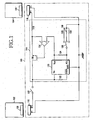
- Fig. 1 is a circuit diagram illustrating a charging apparatus 100 connected between a supplying side terminal 102 and a receiving side terminal 104 in accordance with a first embodiment of the present invention.
- the receiving side terminal 104 represents a terminal with a battery that is to be charged.
- the supplying side terminal 102 represents another terminal capable of supplying electric power from its own battery to the battery of the receiving side terminal 104 through the charging apparatus 100 when the battery of the supplying side terminal 102 has sufficient electric power. That is, Fig. 1 is a view explaining an operation of charging a battery (not shown) of the receiving side terminal 104 by supplying electric power of a battery (not shown) of the supplying side terminal 102 to the battery of the receiving side terminal 104 through the charging apparatus 100.
- the charging apparatus 100 includes a first connector 110 for connecting to a data communication connector 106 contained in the supplying side terminal 102 and a second connector 116 for connecting to a data communication connector 108 contained in the receiving side terminal 104.
- the first and second connectors 110 and 116 include power supply terminals P+ and ground terminals P- for connecting to power supply terminals included in the terminals 102 and 104.
- the first and second connectors 110 and 116 are configured to electrically connect to the data communication connectors 106 and 108 of the terminals 102 and 104 through the terminals P+ and P-.
- the structure and size of charging apparatus 100 is essentially the same as that of a conventional data communication cable that connects data communication connectors conventional terminals.
- the ground terminal P- of the first connector 110 is connected to the ground terminal P- of the second connector 116.
- the power supply terminal P+ of the first connector 110 is connected to an input terminal of a charging controller 114 through a switch 112 and the power supply terminal P+ of the second connector 116 is connected to an output terminal of the charging controller 114.
- the charging controller 114 controls a charge voltage level so that electric power is supplied from the battery of the supplying side terminal 102 to the battery of the receiving side terminal 104 through the power supply terminal P+ and the ground terminal P- of the second connector 116, until the battery voltage level of the receiving side terminal reaches a predetermined charge voltage level set by a user.
- the switch 112 is switched by the user's operation and a path of supplying electric power between the power supply terminal of the first connector 110 and the charging controller 114 is connected and disconnected in response to a turn-on or turn-off state of the switch 112.
- the switch 112 and a current limit resistor 118 are connected to a source and a drain of a FET (Field Effect Transistor) 136, respectively.
- a gate of the FET 136 is connected to an output of a comparator 134.
- the current limit resistor 118 is connected between the drain of the FET 136 and the power supply terminal P+ of the second connector 116.
- the current limit resistor 118 protects the batteries of the supplying side terminal 102 and the receiving side terminal 104 from electrical surges, which may occur during the charging.
- a non-inversion input terminal (+) of the comparator 134 is connected to the drain of the FET 136 and the current limit resistor 118, while an inversion input terminal (-) of the comparator 134 is connected to a voltage output terminal V OUT of a voltage regulator 120.
- the voltage regulator 120 is enabled while voltage of a logic high signal is applied to a shutdown control input terminal SHDN outputting a variable voltage output.
- voltage that is inputted in an input terminal V IN varies with a level of voltage applied to an output voltage adjustment terminal ADJ and is outputted to a voltage output terminal V OUT .
- "TC1174" made by Microchip Technology Inc. can be employed as the voltage regulator 120.
- a first resistor 122 is connected between the input terminal V IN and the shutdown control input terminal SHDN .
- a second resistor 124 is connected between the voltage output terminal V OUT and the output voltage adjustment terminal ADJ.
- Three resistors 128, 130 and 132 having different resistance values are connected together at one end, to provide connections of different resistance between the output voltage adjustment control ADJ and ground through a charge level selection switch 126.
- the charge level selection switch 126 is switched by the user's operation and one of the resistors 128, 130 and 132 is selected according to the switching of the charge level selection switch 126.
- the selected resistor 128, 130 or 132 is connected to the resistor 124.
- voltage outputted to the voltage output terminal V OUT of the voltage regulator 120 is divided by one of the resistors 128,130 and 132 and the resistor 124 and applied to the output voltage adjustment terminal ADJ of the voltage regulator 120. Accordingly, the voltage outputted at the voltage output terminal V OUT of the voltage regulator 120 is varied by the switching of the charge level selection switch 126.
- the FET 136 Since the voltage output terminal V OUT of the voltage regulator 120 is connected to the inversion input terminal (-) of the comparator 134, the FET 136 is turned on while the level of the battery voltage of the receiving side terminal 104 is lower than that a level of output voltage of the voltage output terminal V OUT of the voltage regulator 120. On the other hand, the FET 136 is turned off when the level of the battery voltage of the receiving side terminal 104 is higher than that a level of output voltage of the voltage output terminal V OUT of the voltage regulator 120. Accordingly, the battery of the receiving side terminal 104 is charged until its battery voltage level reaches the charge voltage level based on the resistor 128, 130 or 132 selectively set by the user among three charge voltage levels based on the resistors 128, 130 and 132.
- the number of the resistors is three, but the number of the resistors can be more or less than three. An increased number of resistors allows the user to select a correspondingly increased number of charge voltage levels through the charge level selection switch 126
- the first and second connectors 110 and 116 of the charging apparatus 100 are connected to the data communication connector 106 of the supplying side terminal 102 and the data communication connector 108 of the receiving side terminal 104, respectively.
- the user can set the charge voltage level of the receiving side terminal 104 by manipulating the charge level selection switch 126. If the user then turns the switch 112 on, the battery of the receiving side terminal 104 is charged by the battery power of the supplying side terminal 102. Thereafter, if the battery voltage level of the receiving side terminal 102 reaches the charge voltage level set through the charge level selection switch 126 by the user, the FET 136 is turned off and the charging is stopped.
- the entire charging apparatus 100 can be made in the form of a cable having first and second connectors 110 and 116. Therefore, the user can carry the charging apparatus 100 more conveniently than a conventional terminal charger.
- the switch 112 and the charging controller 114 can be made in one body together with one of the first or second connectors 110 and 116. Alternatively, the switch 112 and the charging controller 114 can be made so that they are arranged in a middle of a cable connected between the first and second connectors 110 and 116.
- the user can charge the battery of the user's terminal using the battery of another terminal in places where the conventional charger cannot be used or where the user would not carry the conventional charger.
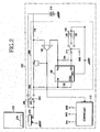
- Fig. 2 is a circuit diagram illustrating a charging apparatus embedded in a mobile communication terminal in accordance with a second embodiment of the present invention. That is, Fig. 2 illustrates a case where a charging apparatus is embedded in a terminal 200 so that the user can charge the battery of the terminal 200 using the battery of an other terminal without carrying the charging apparatus 100 shown in Fig. 1 . Some components included in the terminal 200 not directly associated with the present invention are omitted in Fig. 2 .
- terminal 216 is typically the supplying side terminal.
- terminal 216 can be a receiving side terminal when equipped with charging apparatus such as in terminal 200.
- the terminals 200 and 216 include data communication connectors 202 and 218, respectively.
- a ground terminal P- of the data communication connector 202 included in the terminal 200 is grounded.
- a power supply terminal P+ of the data communication connector 202 of the terminal 200 is connected to a charging controller 208 through a first switch 204 (SW1) and to a plus (+) terminal of a battery 210 of the terminal 200 through a second switch 206.
- the data communication connector 202 is connected to the data communication connector 218 of the terminal 216, typically through a conventional data communication cable (not shown).
- the first switch 204 is diversely turned on/off (i.e. opened) so that its on/off state is opposite to the on/off state of the second switch 206.
- the first switch 204 is turned off, but the second switch 206 is turned on (i.e. closed).
- the first switch 204 is turned on and the second switch 206 is turned off.
- the first and second switches 204 and 206 are kept in the initial (or default) state.
- the first and second switches 204 and 206 are switched by control of a controller 212 which typically is also employed as a main controller of the terminal 200.
- a charge level selection switch 214 included in the charging controller 208 is similar to the charge level selection switch 126 shown in Fig. 1 , except that the switching of the charge level selection switch 214 is preferably controlled by the controller 212. That is, the first and second switches 204 and 206 are switched in response to first and second switching control signals SW1 and SW2 outputted from the controller 212.
- the charge level selection switch 214 is switched in response to a third switching control signal SW3 outputted from the controller 212.
- each of the first and second switches 204 and 206 is turned on or off, but the charge level selection switch 214 is switched in three stages.
- the terminal 200 is configured so that the controller 212 can control the switching of the first and second switches 204 and 206 as well as the charge level selection switch 214.
- the user can use the charging function of the present invention by selecting an option for the charging function in a menu displayed on a display module (not shown) of the terminal 200.
- the charging function can be added to a conventional menu as an "inter-terminal charging mode" so that the user can use it.
- other switches capable of being operated by the user can be exposed and installed on an outside of the terminal 200.
- other switches corresponding to the first and second switches 204 and 206 are preferably diversely turned on or off opposite to each other and controlled by a single user operation.
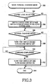
- a flow chart of Fig. 3 having steps 300 to 314 illustrating an operation of the controller 212 according to an embodiment of the present invention.
- the electric power of the battery (not shown) of the supplying side terminal 216 can charge the battery 210 of the receiving side terminal 200.
- the electric power of the battery 210 of the supplying side terminal 200 can charge the battery of the receiving side terminal 216.
- the user connects the data communication connector 218 of the terminal 216 and the data communication connector 202 of the terminal 200 using the data communication cable.
- the user selects the inter-terminal charging mode in accordance with the present invention in the menu displayed on the display module (not shown) of the terminal 200 at step 300.
- the controller 212 waits for the charge voltage level selection by the user at step 302. If the user selects any one of selectable charge voltage levels in the menu for the charging mode through the charge level selection switch 214, the controller 212 controls the switching of the charge level selection switch 214 in response to the selected charge voltage level at step 304 and then proceeds to step 306. If no charge voltage level is selected in step 302, the controller 212 leaves the charge level selection switch 214 in the default state and then proceeds to step 306. The controller 212 waits for the selection of an internal charging mode by the user at the above step 306.
- the internal charging mode means that the battery 210 of the terminal 200, as the receiving side terminal, is to be charged the electric power of the battery of the supplying side terminal 216.
- the internal charging mode is not selected means that the electric power of the battery 210 of the terminal 200, as the supplying side terminal, is to charge the battery of the receiving side terminal 216.
- the first switch 204 should be turned on and the second switch 206 should be turned off because the battery 210 is being charged by electric power inputted from the battery of the supplying side terminal 216 through the data communication connector 202 via a first path.
- the first switch 204 should be turned off and the second switch 206 should be turned on because the electric power of the battery 210 of the terminal 200, as the supplying side terminal, is to charge the receiving side terminal 216 through the data communication connector 202 via a second path.
- Conventional data communication is being accomplished irrespectively of the charging function.
- the controller 212 controls the first and second switches 204 and 206 so that the first switch 204 can be turned on and the second switch 206 can be turned off (step 308). Otherwise, if the internal charging mode is not selected, the controller 212 leaves the first and second switches 204 and 206 in the default state where the first switch 204 and the second switch 206 are maintained in the turn-off state and the turn-on state, respectively.
- the controller 212 ends the inter-terminal charging mode at step 314.
- the electric power inputted from the supplying side terminal 216 through the data communication connector 202 is inputted into the charging controller 208 through the first switch 204 and then the battery 210 is charged up to the charge voltage level selected by the user through an operation of the charging controller 208 similar to the operation of the charging controller 114 described in regard to Fig. 1 .
- the controller 212 determines at step 310 whether the charging has been completed. This is determined by an output of the comparator 134. The output of the comparator 134 is applied to the gate of the FET 136, shown in Figs. 1 and 2 , and is also applied to the controller 212 shown in Fig. 2 .
- the controller 212 recognizes the fact that the charging has been completed up to the charge voltage level set by the user. If so, the controller 212 controls the first and second switches 204 and 206 so that the first switch 204 can be turned off and the second switch 206 can be turned on at step 312. That is, the first and second switches 204 and 206 return to the default state.
- the inter-terminal charging mode ends.
- the user need only carry a conventional data communication connector to charge the battery of the user's terminal from another terminal in places where the conventional charger cannot be used or where the user would not carry the conventional charger.
- the user can supply the electric power from the battery of the terminal 200, acting as the supplying side terminal, to charge the battery of the receiving side terminal 216 where the receiving side terminal 216 has a built-in charging apparatus such as the terminal 200 shown in Fig. 2 , or can be connected to the terminal 200 by the charging apparatus 100 shown in Fig. 1 .
- the receiving side terminal 216 has a built-in charging apparatus such as the terminal 200
- the receiving side terminal 216 performs the charging control operation as in Fig. 3
- the receiving side terminal 216 is connected to the terminal 200 by the charging apparatus 100 shown in Fig. 1
- the charging apparatus 100 performs the charging control operation as in Fig. 1 .
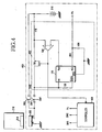
- Fig. 4 is a circuit diagram illustrating a charging apparatus embedded in a mobile communication terminal in accordance with another example of the second embodiment of the present invention.
- Fig. 4 illustrates a terminal 400 equipped with a charging controller 402 in which a predetermined charge voltage level can be set by a pulse signal output Pc from a controller 408, without using the charge level selection switch 214 or the resistors 128, 130 and 132 within the charging controller 208 shown in Fig. 2 .
- the controller 408 outputs the pulse signal Pc to set the battery charge level based on a PWM (Pulse Width Modulation) pulse or a PDM (Pulse Density Modulation) pulse.
- PWM Pulse Width Modulation
- PDM Pulse Density Modulation
- An integrating circuit made up of a resistor 404 and a capacitor 406 is arranged between the output voltage adjustment terminal ADJ of the voltage regulator 120 and an output terminal of the pulse signal Pc of the controller 408. Neither the charge level selection switch (214, 126) nor the resistors 124, 128, 130 and 132 are required.
- the pulse signal Pc outputted from the controller 408 is converted into DC (Direct Current) voltage by the integrating circuit made up of the resistor 404 and the capacitor 406 and then applied to the output voltage, adjustment terminal ADJ of the voltage regulator 120.
- the controller 408 outputs the pulse signal Pc having pulse width or pulse density corresponding to the charge voltage level selected by the user in order to decide the battery voltage level.
- the terminal 400 does not use the charge level selection switch 214 or the resistors 124, 128, 130 and 132 shown in Figs. 1 and 2 , the terminal 400 allows the user to select a desired charge voltage level among an increased number of charge voltage levels.
- the present invention allows the user to charge the battery of the user's terminal using the battery of another terminal in places where the user cannot use the conventional charger or where the user does not carry the conventional charger, if the user either carries the portable charging apparatus 100 or carries the conventional data communication cable and has a mobile terminal with the embedded charging apparatus.
Claims (6)
- Vorrichtung (100) zum Laden einer Batterie eines Empfangsseiten-Mobilkommunikations-Endgerätes (104), das einen zweiten Datenübertragungsverbinder (108) hat, mit Strom einer Batterie eines Zuführseiten-Mobilkommunikations-Endgerätes (102), das einen ersten Datenübertragungsverbinder (106) hat, wobei die Vorrichtung umfasst:einen ersten Verbinder (110) mit einem Stromzuführanschluss (P+) zum Verbinden mit einem Stromzuführanschluss (P+) des ersten Datenübertragungsverbinders (106), wobei der erste Verbinder (110) so ausgeführt ist, dass er Verbindung mit dem ersten Datenübertragungsverbinder (106) eines Zuführseiten-Mobilkommunikations-Endgerätes (102) herstellt;einen zweiten Verbinder (116) mit einem Stromzuführanschluss (P+) zum Verbinden mit dem Stromzuführanschluss (P+) des zweiten Datenübertragungsverbinders (108), wobei der zweite Verbinder (116) so ausgeführt ist, dass er Verbindung mit dem zweiten Datenübertragungsverbinder (108) des Empfangsseiten-Mobilkommunikations-Endgerätes (104) herstellt, das den Ladestrom empfängt;eine Lade-Steuereinheit (114), mit der Ladestrom von dem Stromzuführanschluss (P+) des ersten Verbinders (110) zu der Batterie des Empfangsseiten-Mobilkommunikations-Endgerätes (104) über den Stromzuführanschluss (P+) des zweiten Verbinders (116) zugeführt wird, bis ein Batteriespannungspegel des Empfangsseiten-Mobilkommunikations-Endgerätes (104) einen vorgegebenen Ladespannungspegel erreicht; und einen Schalter (112), mit dem Verbindung auf einem Ladestromweg zwischen dem Stromzuführanschluss (P+) des ersten Verbinders und der Lade-Steuereinheit (114) hergestellt und unterbrochen wird.
- Vorrichtung nach Anspruch 1, wobei die Lade-Steuereinheit (114) des Weiteren enthält:einen Ladepegel-Wählschalter (126), mit dem einer einer Vielzahl vorgegebener Ladespannungspegel selektiv eingestellt wird.
- Mobilkommunikations-Endgerät (200, 400), das einen Datenübertragungsverbinder (202) hat und umfasst:eine Lade-Steuereinheit (208), mit der eine Batterie (210) des Mobilkommunikations-Endgerätes (200) geladen wird, indem Ladestrom von dem Datenübertragungsverbinder (202) der Batterie (210) über einen ersten Weg zugeführt wird, bis ein Batteriespannungspegel des Mobilkommunikations-Endgerätes (200) einen vorgegebenen Ladespannungspegel erreicht;einen ersten Schalter (204), mit dem Verbindung auf dem ersten Ladestromweg hergestellt und unterbrochen wird, wobei der erste Weg zwischen dem Datenübertragungsverbinder (202), der Lade-Steuereinheit (208) und der Batterie (210) verläuft; undeinen zweiten Schalter (206), mit dem Verbindung auf einem zweiten Ladestromweg hergestellt und unterbrochen wird, wobei der zweite Weg zwischen dem Datenübertragungsverbinder (202) und der Batterie (210) verläuft,wobei der erste Schalter (204) und der zweite Schalter (206) so ausgeführt sind, dass sie auf verschiedene Weise so an/ausgeschaltet werden, dass ihre An/Aus-Zustände entgegengesetzt zueinander sind.
- Mobilkommunikations-Endgerät (200, 400) nach Anspruch 3, wobei die Lade-Steuereinheit (208) des Weiteren enthält:einen Ladepegel-Wählschalter (114), mit dem einer einer Vielzahl vorgegebener Ladespannungspegel selektiv eingestellt wird.
- Mobilkommunikations-Endgerät (200, 400) nach Anspruch 3 oder 4, das des Weiteren umfasst:eine Steuereinheit (212, 408), mit der der erste und der zweite Schalter (204, 206) so gesteuert werden, dass der erste Schalter (204) angeschaltet werden kann und der zweite Schalter (206) ausgeschaltet werden kann, bis der Batteriespannungspegel des Mobilkommunikations-Endgerätes (200, 400) den durch einen Benutzer eingestellten vorgegebenen Ladespannungspegel erreicht.
- Mobilkommunikations-Endgerät (200, 400) nach Anspruch 5, wobei die Steuereinheit (212, 408) so eingerichtet ist, dass, nur wenn der Benutzer entscheidet, dass die Batterie (210) des Mobilkommunikations-Endgerätes (200, 400) mit dem Ladestrom geladen wird, der über den ersten Weg von dem Datenübertragungsverbinder (202) zugeführt wird, der erste Schalter (204) angeschaltet wird und der zweite Schalter (206) ausgeschaltet wird.
Applications Claiming Priority (2)
| Application Number | Priority Date | Filing Date | Title |
|---|---|---|---|
| KR2002060821 | 2002-10-05 | ||
| KR10-2002-0060821A KR100493080B1 (ko) | 2002-10-05 | 2002-10-05 | 휴대용 통신 단말기의 배터리 충전장치 |
Publications (3)
| Publication Number | Publication Date |
|---|---|
| EP1406366A2 EP1406366A2 (de) | 2004-04-07 |
| EP1406366A3 EP1406366A3 (de) | 2006-10-11 |
| EP1406366B1 true EP1406366B1 (de) | 2009-06-24 |
Family
ID=31987544
Family Applications (1)
| Application Number | Title | Priority Date | Filing Date |
|---|---|---|---|
| EP03007497A Expired - Fee Related EP1406366B1 (de) | 2002-10-05 | 2003-04-07 | Batterieladevorrichtung für ein mobiles Kommunikationsendgerät |
Country Status (5)
| Country | Link |
|---|---|
| US (1) | US6977486B2 (de) |
| EP (1) | EP1406366B1 (de) |
| KR (1) | KR100493080B1 (de) |
| CN (1) | CN1323479C (de) |
| DE (1) | DE60328072D1 (de) |
Cited By (3)
| Publication number | Priority date | Publication date | Assignee | Title |
|---|---|---|---|---|
| US8634761B2 (en) | 2008-09-08 | 2014-01-21 | Apple Inc. | Cross-transport authentication |
| US9160541B2 (en) | 2006-06-27 | 2015-10-13 | Apple Inc. | Method and system for authenticating an accessory |
| US9223958B2 (en) | 2005-01-07 | 2015-12-29 | Apple Inc. | Accessory authentication for electronic devices |
Families Citing this family (20)
| Publication number | Priority date | Publication date | Assignee | Title |
|---|---|---|---|---|
| KR100965876B1 (ko) * | 2003-06-03 | 2010-06-24 | 삼성전자주식회사 | Usb를 이용한 배터리 충전장치 및 이를 구비하는디지털 카메라 |
| KR200330467Y1 (ko) * | 2003-08-01 | 2003-10-17 | (주) 피엔텔레컴 | 전원공급원 자동 인식 충전형 데이터 통신 케이블 |
| US8086281B2 (en) * | 2007-01-06 | 2011-12-27 | Apple Inc. | Apparatuses and methods that facilitate the transfer of power and information among electrical devices |
| TWI334235B (en) * | 2006-12-20 | 2010-12-01 | Compal Electronics Inc | Device of battery power management having universal serial bus connector |
| US9806772B2 (en) | 2007-01-06 | 2017-10-31 | Apple Inc. | Apparatuses and methods that facilitate the transfer of power and information among radio frequency-based devices |
| US8401473B2 (en) * | 2007-01-06 | 2013-03-19 | Apple Inc. | Apparatuses and methods that facilitate the transfer of power and information among electrical devices |
| US7902794B2 (en) * | 2007-07-03 | 2011-03-08 | Intersil Americas Inc. | Over-voltage protected battery charger with bypass |
| US8222869B2 (en) * | 2007-07-05 | 2012-07-17 | O2Micro, Inc | System and method for battery charging |
| KR101474421B1 (ko) * | 2007-11-23 | 2014-12-19 | 엘지전자 주식회사 | 충전메뉴 설정기능을 갖는 이동 단말기 및 이를 이용한상호 충전방법 |
| US20090134836A1 (en) * | 2007-11-27 | 2009-05-28 | Motorola, Inc. | Devices and methods for electronic device recharging |
| US7928698B2 (en) * | 2008-03-25 | 2011-04-19 | Spx Corporation | Battery charging apparatus and method |
| US9632969B2 (en) * | 2012-08-07 | 2017-04-25 | Google Inc. | Systems and methods for managing a wireless connection between a computing device and a peripheral module |
| CN103475068B (zh) * | 2013-09-30 | 2016-03-23 | 小米科技有限责任公司 | 一种充电器、充电终端、充电系统及充电控制方法 |
| US9711983B2 (en) | 2014-04-09 | 2017-07-18 | Blackberry Limited | Device, system and method for charging a battery |
| US20150349554A1 (en) | 2014-06-03 | 2015-12-03 | Traxxas Lp | Battery connection method and apparatus |
| US10396568B2 (en) | 2014-06-03 | 2019-08-27 | Traxxas Lp | Battery charger with user interface |
| US10431992B2 (en) * | 2014-06-03 | 2019-10-01 | Traxxas Lp | Battery charger with user interface |
| KR20180045954A (ko) * | 2016-10-26 | 2018-05-08 | 현대자동차주식회사 | 배터리 관리 시스템 및 그 제어방법 |
| JP2018050469A (ja) * | 2017-12-21 | 2018-03-29 | オズマ株式会社 | 充電ケーブル及び充電器 |
| US11320969B2 (en) * | 2019-09-16 | 2022-05-03 | Snap Inc. | Messaging system with battery level sharing |
Family Cites Families (12)
| Publication number | Priority date | Publication date | Assignee | Title |
|---|---|---|---|---|
| US5333177A (en) * | 1991-10-19 | 1994-07-26 | Cell Port Labs, Inc. | Universal connection for cellular telephone interface |
| US5661634A (en) * | 1993-11-09 | 1997-08-26 | Fujitsu Limited | Information processing system using portable terminal unit and data communication adapter therefor |
| US5936381A (en) * | 1998-01-13 | 1999-08-10 | Suh; Soo Chan | Charging apparatus for car storage batteries |
| KR19990085923A (ko) * | 1998-05-22 | 1999-12-15 | 윤종용 | 무선전화기의 보조전원 공급장치 |
| JP2000201204A (ja) * | 1999-01-08 | 2000-07-18 | Mitsumi Electric Co Ltd | 携帯電話用補助充電装置 |
| JP3318554B2 (ja) * | 1999-03-25 | 2002-08-26 | ソースネクスト株式会社 | USB(UniversalSerialBus)ケーブル及びUSBケーブルによる外部装置への充電方法 |
| CA2275041C (en) * | 1999-06-17 | 2008-01-22 | Vtech Communications, Ltd. | Method and apparatus of extending useful life of a cordless telephone during a power outage condition |
| DE10008600A1 (de) * | 2000-02-24 | 2001-09-06 | Siemens Ag | Mobiles Mehrgerätesystem |
| KR20020014870A (ko) * | 2000-08-19 | 2002-02-27 | 공종열 | Usb를 이용한 이동전화 충전장치 |
| KR100442360B1 (ko) * | 2001-09-12 | 2004-07-30 | 엘지전자 주식회사 | 충전된 휴대폰을 이용한 휴대폰 충전 장치 |
| KR100458095B1 (ko) * | 2001-12-05 | 2004-11-26 | 김남진 | 휴대폰의 배터리 충전시스템 |
| KR20030062978A (ko) * | 2002-01-21 | 2003-07-28 | 김대욱 | 방전된 핸드폰의 응급복구장치 |
-
2002
- 2002-10-05 KR KR10-2002-0060821A patent/KR100493080B1/ko not_active IP Right Cessation
-
2003
- 2003-01-30 US US10/354,631 patent/US6977486B2/en not_active Expired - Lifetime
- 2003-03-27 CN CNB031083161A patent/CN1323479C/zh not_active Expired - Fee Related
- 2003-04-07 DE DE60328072T patent/DE60328072D1/de not_active Expired - Lifetime
- 2003-04-07 EP EP03007497A patent/EP1406366B1/de not_active Expired - Fee Related
Cited By (5)
| Publication number | Priority date | Publication date | Assignee | Title |
|---|---|---|---|---|
| US9223958B2 (en) | 2005-01-07 | 2015-12-29 | Apple Inc. | Accessory authentication for electronic devices |
| US9754099B2 (en) | 2005-01-07 | 2017-09-05 | Apple Inc. | Accessory authentication for electronic devices |
| US10049206B2 (en) | 2005-01-07 | 2018-08-14 | Apple Inc. | Accessory authentication for electronic devices |
| US9160541B2 (en) | 2006-06-27 | 2015-10-13 | Apple Inc. | Method and system for authenticating an accessory |
| US8634761B2 (en) | 2008-09-08 | 2014-01-21 | Apple Inc. | Cross-transport authentication |
Also Published As
| Publication number | Publication date |
|---|---|
| EP1406366A2 (de) | 2004-04-07 |
| KR100493080B1 (ko) | 2005-06-02 |
| DE60328072D1 (de) | 2009-08-06 |
| EP1406366A3 (de) | 2006-10-11 |
| US6977486B2 (en) | 2005-12-20 |
| US20040066174A1 (en) | 2004-04-08 |
| CN1487646A (zh) | 2004-04-07 |
| CN1323479C (zh) | 2007-06-27 |
| KR20040031394A (ko) | 2004-04-13 |
Similar Documents
| Publication | Publication Date | Title |
|---|---|---|
| EP1406366B1 (de) | Batterieladevorrichtung für ein mobiles Kommunikationsendgerät | |
| KR101913711B1 (ko) | 모바일 기기 충전기의 적응형 충전 전압 생성기 | |
| KR100254478B1 (ko) | 충방전 제어장치 및 정전압 정전류 제어회로 | |
| US7692400B2 (en) | Mobile type power supply, connection device, and carried type electronic equipment | |
| EP0450783B1 (de) | Batterieladesystem | |
| EP2501016A2 (de) | Integriertes Batterieladegerät | |
| CN1413374A (zh) | 对电池充电的方法和装置 | |
| US6552512B1 (en) | Portable device charger based on audio energy power | |
| EP0641089A2 (de) | Tragbares Funkgerät mit Batterien für die Versorgung von verschiedenen Speisespannungen | |
| AU683475B2 (en) | Electronic device having internal charge regulator | |
| JP4221665B2 (ja) | 携帯端末装置 | |
| JP3430466B2 (ja) | 二次電池の充電装置 | |
| KR20070109017A (ko) | 이동형 전자기기의 외부 보조 배터리 | |
| KR101728881B1 (ko) | 하나의 포트를 이용한 보조배터리와 보조배터리의 충방전 제어방법 | |
| CA2657770A1 (en) | Power converter with integral battery | |
| WO2005122360A1 (ja) | 携帯電源装置 | |
| KR20170098461A (ko) | 휴대 단말을 이용한 외부 기기의 전원 공급 장치 | |
| KR20060080652A (ko) | 휴대용 충전장치 | |
| KR200284119Y1 (ko) | 유에스비 데이터 통신 케이블장치 | |
| KR200394884Y1 (ko) | 충전케이블 장치 | |
| KR20070092074A (ko) | 전원공급장치 및 전원공급장치의 전원 공급방법 | |
| JPH08149716A (ja) | 無線通信装置用充電器 | |
| KR100565310B1 (ko) | 이동 통신 단말기 | |
| JP2001211564A (ja) | カメラの電源装置 | |
| JP2004134915A (ja) | 外部接続装置および電圧供給方法 |
Legal Events
| Date | Code | Title | Description |
|---|---|---|---|
| PUAI | Public reference made under article 153(3) epc to a published international application that has entered the european phase |
Free format text: ORIGINAL CODE: 0009012 |
|
| 17P | Request for examination filed |
Effective date: 20030407 |
|
| AK | Designated contracting states |
Kind code of ref document: A2 Designated state(s): AT BE BG CH CY CZ DE DK EE ES FI FR GB GR HU IE IT LI LU MC NL PT SE SI SK TR |
|
| AX | Request for extension of the european patent |
Extension state: AL LT LV MK RO |
|
| PUAL | Search report despatched |
Free format text: ORIGINAL CODE: 0009013 |
|
| AK | Designated contracting states |
Kind code of ref document: A3 Designated state(s): AT BE BG CH CY CZ DE DK EE ES FI FR GB GR HU IE IT LI LU MC NL PT SE SI SK TR |
|
| AX | Request for extension of the european patent |
Extension state: AL LT LV MK RO |
|
| 17Q | First examination report despatched |
Effective date: 20070213 |
|
| AKX | Designation fees paid |
Designated state(s): DE FR GB |
|
| GRAP | Despatch of communication of intention to grant a patent |
Free format text: ORIGINAL CODE: EPIDOSNIGR1 |
|
| GRAS | Grant fee paid |
Free format text: ORIGINAL CODE: EPIDOSNIGR3 |
|
| GRAA | (expected) grant |
Free format text: ORIGINAL CODE: 0009210 |
|
| AK | Designated contracting states |
Kind code of ref document: B1 Designated state(s): DE FR GB |
|
| REG | Reference to a national code |
Ref country code: GB Ref legal event code: FG4D |
|
| REF | Corresponds to: |
Ref document number: 60328072 Country of ref document: DE Date of ref document: 20090806 Kind code of ref document: P |
|
| PLBE | No opposition filed within time limit |
Free format text: ORIGINAL CODE: 0009261 |
|
| STAA | Information on the status of an ep patent application or granted ep patent |
Free format text: STATUS: NO OPPOSITION FILED WITHIN TIME LIMIT |
|
| 26N | No opposition filed |
Effective date: 20100325 |
|
| REG | Reference to a national code |
Ref country code: FR Ref legal event code: PLFP Year of fee payment: 14 |
|
| REG | Reference to a national code |
Ref country code: FR Ref legal event code: PLFP Year of fee payment: 15 |
|
| PGFP | Annual fee paid to national office [announced via postgrant information from national office to epo] |
Ref country code: GB Payment date: 20170322 Year of fee payment: 15 |
|
| PGFP | Annual fee paid to national office [announced via postgrant information from national office to epo] |
Ref country code: FR Payment date: 20170424 Year of fee payment: 15 Ref country code: DE Payment date: 20170420 Year of fee payment: 15 |
|
| REG | Reference to a national code |
Ref country code: DE Ref legal event code: R119 Ref document number: 60328072 Country of ref document: DE |
|
| GBPC | Gb: european patent ceased through non-payment of renewal fee |
Effective date: 20180407 |
|
| PG25 | Lapsed in a contracting state [announced via postgrant information from national office to epo] |
Ref country code: DE Free format text: LAPSE BECAUSE OF NON-PAYMENT OF DUE FEES Effective date: 20181101 |
|
| PG25 | Lapsed in a contracting state [announced via postgrant information from national office to epo] |
Ref country code: GB Free format text: LAPSE BECAUSE OF NON-PAYMENT OF DUE FEES Effective date: 20180407 |
|
| PG25 | Lapsed in a contracting state [announced via postgrant information from national office to epo] |
Ref country code: FR Free format text: LAPSE BECAUSE OF NON-PAYMENT OF DUE FEES Effective date: 20180430 |