EP1393618A1 - Storage tray for storing and watering plants, and watering device - Google Patents
Storage tray for storing and watering plants, and watering device Download PDFInfo
- Publication number
- EP1393618A1 EP1393618A1 EP03018501A EP03018501A EP1393618A1 EP 1393618 A1 EP1393618 A1 EP 1393618A1 EP 03018501 A EP03018501 A EP 03018501A EP 03018501 A EP03018501 A EP 03018501A EP 1393618 A1 EP1393618 A1 EP 1393618A1
- Authority
- EP
- European Patent Office
- Prior art keywords
- storage platform
- storage
- overflow
- irrigation device
- platforms
- Prior art date
- Legal status (The legal status is an assumption and is not a legal conclusion. Google has not performed a legal analysis and makes no representation as to the accuracy of the status listed.)
- Granted
Links
Images


Classifications
-
- A—HUMAN NECESSITIES
- A01—AGRICULTURE; FORESTRY; ANIMAL HUSBANDRY; HUNTING; TRAPPING; FISHING
- A01G—HORTICULTURE; CULTIVATION OF VEGETABLES, FLOWERS, RICE, FRUIT, VINES, HOPS OR SEAWEED; FORESTRY; WATERING
- A01G9/00—Cultivation in receptacles, forcing-frames or greenhouses; Edging for beds, lawn or the like
- A01G9/04—Flower-pot saucers
-
- A—HUMAN NECESSITIES
- A47—FURNITURE; DOMESTIC ARTICLES OR APPLIANCES; COFFEE MILLS; SPICE MILLS; SUCTION CLEANERS IN GENERAL
- A47B—TABLES; DESKS; OFFICE FURNITURE; CABINETS; DRAWERS; GENERAL DETAILS OF FURNITURE
- A47B31/00—Service or tea tables, trolleys, or wagons
- A47B2031/004—Service or tea tables, trolleys, or wagons having four vertical uprights
Definitions
- the invention relates to a storage platform for storing, watering and transporting of plants and an irrigation device formed therewith.
- Known storage platforms for the storage and irrigation of plants usually exist from flat screen printing plates, which are reinforced at their edges, for example by angle iron are. Plants are stored on these plates by a hose or other Irrigation facilities are watered. Not immediately from the plants absorbed water flows over the edge of the storage platform, leading to costly and time-consuming irrigation, unnecessarily high water consumption and nevertheless often leads to insufficient watering of the plants.
- the storage platforms are often arranged one above the other. This can result in water from an irrigation upper storage platform flows into a lower, which is not without problems is because the plants in the lower storage platforms are partially watered from above become what is harmful to many plant species.
- the object of the invention is therefore to provide a storage platform that a enables cost-effective and species-appropriate storage and irrigation of plants.
- a storage platform for storage and Irrigation of plants solved wherein the storage platform is trough-shaped and at least one overflow for specifying a desired liquid level having.
- the storage platform can be provided with side walls, for example with vertical to a flat base of the platform.
- the overflow for setting a desired liquid level is adjustable in height.
- the overflow has a tubular discharge element, the fixed or height adjustable in an opening in a floor of the storage platform is held.
- the drainage system or the overflow can be gradual or infinitely variable be height adjustable.
- the diverter element can have optical markings and / or mechanical locking means have predetermined positions. Furthermore, the diverting element can have at least one laterally have directed Ausfluöfrihun, and it can be rotatably held in the opening.
- the discharge element is a hose made of a has elastic material whose outer diameter is larger than the diameter of the Opening is.
- the hose can form its end section forming the overflow expand towards.
- extension element in particular a Extension ring, is inserted.
- an opening in a side wall of the storage platform height-adjustable sliding element is assigned to form the overflow.
- the storage platform holding means for Attaching to a support device in particular on struts of a frame, shelf or Transport trolley.
- the holder means can hooks, eyes, protruding pins or rails.
- the storage platform is rectangular Has floor space.
- the storage platform is rectangular and has two mounting elements for each on two parallel narrow sides Hanging in mounting holes of frame struts, each Bracket element running along the respective narrow side and in the direction of one each first lying longitudinal side has freely ending engagement end portion.
- the engagement end sections of the mounting elements are preferably all in one Corner area of the storage platform arranged.
- the bracket elements can be L-shaped be formed and a holding leg and an engaging end portion forming Have hanging legs.
- the holding legs are expediently on one Side wall attached.
- the engagement end sections are preferably provided with a recess for positive locking Attach it to the frame struts.
- the invention provides that the narrow sides between the mounting elements are each provided with an extension within which an overflow is arranged is.
- the storage platform on a Bottom is provided with rollers. It can also be provided that the storage platform is designed as the lowest storage platform of an irrigation device, is rectangular and is provided in each corner area with a holder for a frame strut.
- a Irrigation device for storing, watering and transporting plants with at least two storage platforms according to the invention arranged one above the other solved, the storage platforms are arranged so that one over the overflow Liquid (each) storage platform draining into a lower one, especially initially adjacent, arranged storage platform can flow.
- the storage platforms are designed and arranged in such a way that that the tubular discharge element of an (each) upper storage platform except for one Bottom of a storage platform arranged underneath, in particular initially adjacent enough.
- a (each) storage platform is located directly on one of them arranged storage platform, i.e. without a separate frame or the like available is.
- the irrigation device has a carrying device, in particular has a frame, shelf or trolley.
- the support means for holding Attachment of storage platforms are provided.
- the holding means are hooks, eyes, protruding pins or rails.
- the invention further provides as a variant that the storage platforms in plan view fan-shaped or in the form of a pyramid.
- a further embodiment of the irrigation device provides that at least two Storage platforms are available, the frame struts each having at least one Have insertion recess for hanging the engagement end portions, the Hook-in recesses from one narrow side of each of the storage platforms associated frame struts are facing each other.
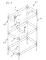
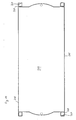
- Fig. 1 is a generally designated 1 embodiment of one Storage platform according to the invention shown.
- the storage platform 1 has one flat floor 3 and side walls 5 arranged perpendicular thereto.
- the overflow 9 is shown in detail in FIG. 2. It has a diverting element 11, which in this embodiment is formed by an elastic hose.
- the hose 11 is closed an overflow forming end portion 13 expanded so that it against a Downward movement is blocked.
- the extension of the hose 11 is a Extension element, e.g. through a brass ring 14, which is inserted into the hose 11, causes.
- the elasticity of the hose 11 allows a sealing within certain limits Height adjustment of the upper hose opening, which ultimately forms the overflow 9. Will the Hose 11 pushed upwards in the opening, so the position at which the Opening 7 is in contact with hose 11, away from end section 13. this leads to due to the elasticity of the hose 11 to an expansion of the hose in the area the new position of the opening 7 and thus a new seal. If, however, the Hose 11 is pushed down, so the position at which the opening moves is in contact with the hose 11, in the direction of the end section 13. This leads to a elastic constriction of the hose 11 in the area of the new position of the opening 7.
- the hose 11 can be in this area have a constant outer diameter over a certain length, which then slightly larger than the diameter of the opening 7 must be a holding and sealing seat of the (elastic) hose 11 in the opening 7 and a To enable height adjustment by moving the hose 11 in the opening 7.
- the discharge element through a plastic tube or metal may be formed sealingly in an opening in the floor of the storage platform is held.
- the tube can have an outer diameter that is slightly larger than the diameter of the opening so that the tube is caused by frictional forces in the opening is held and the height of the overflow edge by pushing or pulling the pipe is adjustable.
- the area between the pipe and the opening can also be determined by a suitable one Seal be sealed.
- the height-adjustable overflow is provided by a sliding element formed, which is located in an opening in the side wall of the storage platform. at If a desired, set level is exceeded, the water flows through a Overflow edge of the sliding element through the opening.
- the sliding element can Example be a plate formed by rails formed on the edge of the opening is led.
- the sliding element is adjustable in height and can be placed in the desired positions be snapped into place. Seals can be located in an area between the sliding element and the opening be made of rubber or plastic.
- the storage platform 1 can be made of plastic, for example, which is reinforced with fibers can, from a corrosion-resistant metal or from a suitable composite material consist.
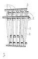
- FIG. 3 shows an embodiment of an irrigation device 17 according to the invention shown, in which three storage platforms 1 according to the invention on frame struts 21 one Frame 23 are arranged one above the other.
- Each storage platform 1 has an overflow 9 on, which is provided with a tube 11 going downwards
- FIG. 3 shows just one example of a hose.
- the free one opposite the overflow 9 End section 19 of the hose 11 ends on or just above the bottom 3 of the next Adjacent Lower Storage Platform 1.
- the one held on the upper storage platform Hose 11 can also above the bottom of the next neighboring, lower Storage platform 1 ends.
- the hose 11 of the lowest storage platform 1 can in a drain or in a storage container for further use of the liquid (e.g. water with additives such as fertilizer or similar).
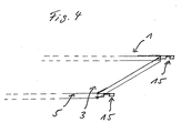
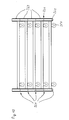
- the storage platforms as indicated in Figure 4, have holding means, e.g. Hooks 15 on the short sides of the rectangular storage platform Protrude lengthwise.
- holding means e.g. Hooks 15 on the short sides of the rectangular storage platform Protrude lengthwise.
- Pins not shown
- the frame struts 21 With this and with corresponding recesses or above Pins (not shown) of the frame struts 21 are the three storage platforms 1 releasably the frame struts 21 of the frame 23 of the irrigation device 17 attached. Also one height-adjustable attachment (infinitely or at fixed intervals) is advisable.
- the holding means 15 shown are arranged in a conventional manner, d. H. as with known storage platforms that are even and without overflow. Because of the on the narrow sides in Longitudinal projecting arrangement of hooks 15, the storage platforms 1 in a frame 23 according to Figure 3 hooked by first two hooks 15, which are on one common narrow side of a storage platform are located in corresponding Recesses of two adjacent frame struts 21 used and as far as possible in these are inserted.
- the hooks 15 can be the opposite Narrow side of the storage platform in alignment with corresponding receiving openings the opposite frame struts 21 of the frame can be moved and under movement
- the storage platform is inserted lengthways into this until all four hooks 15 are approximately the same depth in the four recesses of the frame struts 21.
- this position can indicated in Figure 4 recesses of the hook 15 in the Engage recesses in the frame struts 21 in a form-fitting manner, so that the storage platform is fixed in its desired position.
- the storage platforms 1 can also be staggered, e.g. gradual or fan-like or in the form of a pyramid, which is particularly suitable for exhibition or Suitable for advertising purposes.
- the hoses of the storage platforms are each guided that they drain the water from a storage platform 1 into a deeper, in particular direct the next lower storage platform.
- Storage platforms e.g. Cacti or other plants that need little or no water can do this be ignored.
- the irrigation device 17 can have a mobile base, in particular rollers, have, for example, can be attached to the struts 21 below.
- FIG. 5 shows a further embodiment of an overflow or discharge element 109, which in FIG an opening 107 of a bottom 103 is inserted, for example into another Embodiment of a storage platform 101, which in Figures 6 and 7 in more detail is shown.
- the overflow 109 consists of a cylindrical that is open in one direction (above) Base body 110, which has a circular bottom wall 111 at a lower end is completed.
- a drain opening 112 allows water to flow away from flows into the cylindrical base body 110 via an edge 116 at the top. Go berserk of the overflow 109 about its longitudinal axis 113, the direction of the drain opening 112 and to determine the direction of discharge of the outflowing water. This can be ensured that the water jet running down on a below Storage platform meets. Locking or limiting the angle of rotation can also be provided.
- several drain openings 112 are also possible are arranged distributed over the circumference of the base body 110.
- the base body 110 has several on its outside Provide locking elements 114 (recesses or projections) that a height adjustment in allow predetermined distances, i.e. so that the upper edge 116 of the base body 110 stands at a desired height h above the floor 103, whereby a maximum Water level or level h is specified on the floor.
- optical markings can also be provided, the one Make it easier to set a desired height h.
- a Stop 118 is provided, which is a complete withdrawal of the overflow 109 from the Opening 107 prevented or at least made difficult.
- a paragraph 119 sets a maximum adjustable level (overflow 109 pushed all the way up).
- the stop 118 Because of the stop 118, there is always a residue even when the overflow 109 is completely lowered There is water in the storage platform. If residual emptying is desired, this can be done by placing a notch in the overflow and / or by providing one Deepening in the bottom 103 in the area of the opening 107. It can also be provided be that the bottom 103 is curved or arched, so that on the one hand greater stability is achieved and on the other a slope is achieved so that the water always flows in the direction of the overflow (s). This ensures that the Storage platform can be completely emptied and practically water-free when removed is.
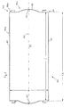
- FIG. 6 to 8 explain the structure of a second embodiment of an inventive Storage platform 101.
- the storage platform 101 is generally rectangular with a Bottom 103, side walls 105, long sides 106b and narrow sides 106a, corners 120 as well two openings 107, in which there are overflows 109, not shown, for example according to FIG. 5 are located.
- An extension 124 is provided in the area of the narrow sides 106a, within which the opening 107 is located. Extension 124 is shown in Embodiment circular, but could also be shaped differently, for example rectangular, triangular or in some other way.
- extension 124 consists of opening 107 or overflow 109 outside a rectangular one Storage area with dimensions L x W can be arranged by the long sides 106b and through straight sections 106c of the narrow sides 106a or in other words through the Corners 120 of the storage platform 101 is fixed (length, width of the inner footprint the storage platform).
- the extension 124 could also be located directly at the corners 120 of the storage platform 101 begin, then said rectangular storage area through the corner points of the Storage platform would be set. It is essential in this context that a Arrangement of the overflow 109 within said rectangular storage area of the Storage platform would be disadvantageous. This is because a set of planters on the storage platform mostly in rectangular collection boxes, for example each six individual planters, the length of which is the width B of the storage platform and whose width corresponds to an integer fraction of their length L. Such one Installation is only within the rectangular storage area mentioned possible.
- the length L of the bearing surface is determined by the fact that the Dimensions and mutual distances between frame struts in one Irrigation device according to Figure 3 (see also Figure 13 to 15 below) in practice due to a large number of existing irrigation devices is specified.
- the dimensions L, B of the storage platform are also indirect specified, within which there should be no overflow.
- the Side walls 105 in the area of the narrow sides 106a of the storage platform 101 in the area the corners 120 or in the vicinity of the long sides 106b, support elements 130 are arranged, which are L-shaped in the illustrated embodiment and a holding leg 132, which is attached to the side wall 105, and one of the holding leg outgoing hanging leg 134, which in the direction of the first longitudinal side 106b ends freely and perpendicular to this and. parallel to the narrow side 106a assigned to it is arranged.
- the hanging leg 134 has a semicircular or slot-shaped recess 136 so that the storage platform 101 in to be explained, suspended in the frame struts of an irrigation device can be.
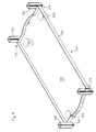
- FIGs 9 to 12 illustrate a further embodiment of an inventive Storage platform 201, which is different from the storage platform 101 after the first Embodiment on the one hand with rollers 250 and on the other hand in the area of the corners 220 each with a receiving means 260 for one (Still explained below and shown in Figures 13 to 15) provided frame strut 221 is.
- the receiving means 260 are in this example on the floor 203 and side walls 205 fastened square tubes with a square cross-section, in the lower area Stop parts 261 in the form of smaller and shorter square tube pieces are used, whose outer contour corresponds to the inner contour of the square tubes 260.
- the measure is, on the one hand, a stop for one into the receiving means 260 from above inserted frame strut 221, with an outer contour of the frame strut in essentially corresponds to the inner contour of the receiving means 260 or at least into it fits in, and on the other hand, by the areas projecting downwards Stop parts 261 reach stackability of the storage platforms 201, which is shown in FIG. 11 and 12 is shown.
- the receiving means 260 could be different Have a cross-sectional shape, e.g. to accommodate frame struts with non-square Cross-section (rectangular, L-shaped, round or shaped in any other way).
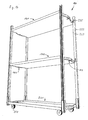
- FIGS. 13 to 15 show different views of a further embodiment of a Irrigation device 117 according to the invention, with a lowermost storage platform 201 according to FIGS. 9 to 12, two storage platforms 101 according to FIGS. 6 to 8 and four in the receiving means 260 of the lowest storage platform 201 used frame struts 221st
- the frame struts 221 are in the form of U-profiles formed, whose cross-sectional shape or outer contour is square (same web and Leg length) and which can therefore be inserted into the receiving means 260 with little play, the stops 261 predefine a defined insertion depth.
- the ones that make up the attacks Square tube pieces 261 can, for example, be inserted just as deeply into the receiving means 260, how they protrude from it.
- FIGS. 13 and 14 also show, the frame struts 221 are inserted in such a way that Leg portions 222 outwards, i.e. towards the long sides 106b of the Storage platforms 102, 201 have, while the leg sections 222 connecting Web sections 223 of the frame struts 221 substantially parallel to the long sides 106b and are thus arranged facing each other.
- the advantages achieved are irrelevant whether leg sections 222 or web sections 223 are arranged facing each other, since it is only important that in A corresponding area of the hanging legs 134 of the support members 130 Material area of a frame strut 221 is available for hanging.
- the web sections 223 each at a desired height with vertical or provided in the longitudinal direction of the struts hanging slots 225 into which the Hanging legs 134 are suspended.
- the recesses 136 encompass the Wall thickness of the material of the web sections 223.
- the U-shaped frame struts 221 shown in FIGS. 13 and 14 could alternatively be used are used rotated by 90 ° about their longitudinal axis compared to the position shown, provided that the suspension slots 225 in the leg sections 222 then facing each other would be introduced.
- An insertion position rotated by 180 ° would only be appropriate Modification, i.e. Extension of the hanging leg 134 possible, although one such arrangement due to the then outwardly projecting ends of the Hanging leg 134 would be less cheap.
- the mounting process of a storage platform 101 takes place in Cross direction, i.e. so that first two of a common long side 106b one Storage legs associated with storage platform 134 in corresponding suspension slots 225 are inserted, then that of a longitudinal axis 126 of the storage platform 101 opposite hanging legs 134 which are assigned to the other long side 106b, brought to the level of the corresponding, opposite hanging slots 225 and in these are inserted.
- Cross direction i.e. so that first two of a common long side 106b one Storage legs associated with storage platform 134 in corresponding suspension slots 225 are inserted, then that of a longitudinal axis 126 of the storage platform 101 opposite hanging legs 134 which are assigned to the other long side 106b, brought to the level of the corresponding, opposite hanging slots 225 and in these are inserted.
- the irrigation device explained in FIGS. 13 to 15 has an arrangement approximately according to Figures 3 and 4, in the support members 15 in the longitudinal direction (parallel to the Long sides of the storage platform) are arranged, the advantage that the outer Length dimension La of the storage platforms 101 (FIG. 6) in the area of the straight one Sections 106c of the narrow sides 106a exactly the inner, clear distance 1 between the Frame struts 221 can correspond without the between the narrow sides 106a
- Storage platforms 101 and the frame struts 221 must be provided a distance which allows the storage platforms to be inserted, as is the case with one version 3 and 4 is necessary, for example, in which the mounting elements in Longitudinal directions of the storage platform run.
- the length gain achieved in this way of a storage platform according to the invention and the above storage area can be several centimeters and has a predetermined distance dimension 1 of the rod struts 221 result in that on each single storage platform 101 more planters can be set up than this is the case with an arrangement, for example according to FIGS. 3 and 4, in which the It is hooked in the longitudinal direction.
- the usable floor space is opposite State of the art enlarged by the invention to the extent that in the plan view between frame struts located in the longitudinal or transverse direction, strip-shaped surface areas are of different sizes and are either usable Footprint belong or not, here also the cross-sectional shape (square or rectangular-elongated) the frame struts play a role.
Abstract
Description
Die Erfindung betrifft eine Lagerungsplattform zum Lagern, Bewässern und Transportieren von Pflanzen sowie eine damit gebildete Bewässerungsvorrichtung.The invention relates to a storage platform for storing, watering and transporting of plants and an irrigation device formed therewith.
Bekannte Lagerungsplattformen zur Lagerung und Bewässerung von Pflanzen bestehen meist aus ebenen Siebdruckplatten, die an ihren Rändern zum Beispiel durch Winkeleisen verstärkt sind. Auf diesen Platten lagern Pflanzen, die durch einen Schlauch oder andere Bewässerungseinrichtungen bewässert werden. Das von den Pflanzen nicht sofort aufgenommene Wasser fließt dabei über den Rand von der Lagerungsplattform ab, was zu einer kosten- und zeitintensiven Bewässerung, einem unnötig hohen Wasserverbrauch und dennoch häufig zu einer unzureichenden Bewässerung der Pflanzen führt.Known storage platforms for the storage and irrigation of plants usually exist from flat screen printing plates, which are reinforced at their edges, for example by angle iron are. Plants are stored on these plates by a hose or other Irrigation facilities are watered. Not immediately from the plants absorbed water flows over the edge of the storage platform, leading to costly and time-consuming irrigation, unnecessarily high water consumption and nevertheless often leads to insufficient watering of the plants.
Aus diesem Grunde, aber auch zur Platzeinsparung, sind die Lagerungsplattformen oft übereinander angeordnet. Dies kann dazu führen, daß beim Bewässern das Wasser aus einer oberen Lagerungsplattform in eine untere fließt, was allerdings auch nicht unproblematisch ist, da dann die Pflanzen in den unteren Lagerungsplattformen teilweise von oben bewässert werden, was für viele Pflanzenarten schädlich ist.For this reason, but also to save space, the storage platforms are often arranged one above the other. This can result in water from an irrigation upper storage platform flows into a lower, which is not without problems is because the plants in the lower storage platforms are partially watered from above become what is harmful to many plant species.
Die Aufgabe der Erfindung besteht daher darin, eine Lagerungsplattform anzugeben, die eine kostengünstige und artgerechte Lagerung und Bewässerung von Pflanzen ermöglicht. The object of the invention is therefore to provide a storage platform that a enables cost-effective and species-appropriate storage and irrigation of plants.
Diese Aufgabe wird erfindungsgemäß durch eine Lagerungsplattform zum Lagern und Bewässern von Pflanzen gelöst, wobei die Lagerungsplattform wannenartig ausgebildet ist und mindestens einen Überlauf zum Vorgeben eines gewünschten Flüssigkeitspegels aufweist. Die Lagerungsplattform kann mit Seitenwänden versehen sein, beispielsweise mit vertikal zu einer ebenen Grundfläche der Plattform stehenden Wänden.This object is achieved by a storage platform for storage and Irrigation of plants solved, wherein the storage platform is trough-shaped and at least one overflow for specifying a desired liquid level having. The storage platform can be provided with side walls, for example with vertical to a flat base of the platform.
Bevorzugt ist vorgesehen, daß der Überlauf zum Einstellen eines gewünschten Flüssigkeitspegels höhenverstellbar ist.It is preferably provided that the overflow for setting a desired liquid level is adjustable in height.
Weiterhin kann vorgesehen sein, daß der Überlauf ein rohrförmiges Ableitelement aufweist, das fest oder höhenverstellbar in einer Öffnung in einem Boden der Lagerungsplattform gehalten ist. Das Ableitsystem bzw. der Überlauf kann stufenweise oder stufenlos höhenverstellbar sein.Furthermore, it can be provided that the overflow has a tubular discharge element, the fixed or height adjustable in an opening in a floor of the storage platform is held. The drainage system or the overflow can be gradual or infinitely variable be height adjustable.
Das Ableitelement kann optische Markierungen und/oder mechanische Rastmittel in vorbestimmten Positionen aufweisen. Ferner kann das Ableitelement mindestens eine seitlich gerichtete Ausflußöfrihun aufweisen, und es kann drehbar in der Öffnung gehalten sein.The diverter element can have optical markings and / or mechanical locking means have predetermined positions. Furthermore, the diverting element can have at least one laterally have directed Ausfluöfrihun, and it can be rotatably held in the opening.
In vorteilhafter Weise ist vorgesehen, daß das Ableitelement einen Schlauch aus einem elastischen Material aufweist, dessen Außendurchmesser größer als der Durchmesser der Öffnung ist. Hierbei kann sich der Schlauch zu seinem den Überlauf bildenden Endabschnitt hin erweitern.It is advantageously provided that the discharge element is a hose made of a has elastic material whose outer diameter is larger than the diameter of the Opening is. Here, the hose can form its end section forming the overflow expand towards.
Es kann vorgesehen sein, daß in den Endabschnitt ein Erweiterungselement, insbesondere ein Erweiterungsring, eingesetzt ist.It can be provided that an extension element, in particular a Extension ring, is inserted.
Außerdem bevorzugt ist, daß einer Öffnung in einer Seitenwand der Lagerungsplattform ein höhenverstellbares Schiebeelement zugeordnet ist, um den Überlauf zu bilden. It is also preferred that an opening in a side wall of the storage platform height-adjustable sliding element is assigned to form the overflow.
In vorteilhafter Weise ist vorgesehen, daß die Lagerungsplattform Halterungsmittel zum Anbringen an einer Trageinrichtung, insbesondere an Streben eines Gestells, Regals oder Transportwagens, aufweist. Die Halterungsmittel können Haken, Ösen, vorstehende Stifte oder Schienen sein.It is advantageously provided that the storage platform holding means for Attaching to a support device, in particular on struts of a frame, shelf or Transport trolley. The holder means can hooks, eyes, protruding pins or rails.
Weiterhin bevorzugt ist vorgesehen, daß die Lagerungsplattform eine rechtwinklige Grundfläche aufweist.It is furthermore preferably provided that the storage platform is rectangular Has floor space.
In bevorzugter Ausgestaltung der Erfindung ist vorgesehen, daß die Lagerungsplattform rechteckig ist und an zwei parallelen Schmalseiten jeweils zwei Halterungselemente zum Einhängen in Befestigungsöffhungen von Gestellstreben aufweist, wobei jedes Halterungselement ein entlang der jeweiligen Schmalseite verlaufendes und in Richtung einer jeweils zunächst liegenden Längsseite frei endenen Eingriffs-Endabschnitt aufweist.In a preferred embodiment of the invention it is provided that the storage platform is rectangular and has two mounting elements for each on two parallel narrow sides Hanging in mounting holes of frame struts, each Bracket element running along the respective narrow side and in the direction of one each first lying longitudinal side has freely ending engagement end portion.
Bevorzugt sind die Eingriffs-Endabschnitte der Halterungselemente jeweils in einem Eckbereich der Lagerungsplattform angeordnet. Die Halterungselemente können L-förmig ausgebildet sein und einen Halteschenkel und einen den Eingriffs-Endabschnitt bildenden Einhängeschenkel aufweisen. Zweckmäßigerweise sind die Halteschenkel an einer Seitenwand befestigt.The engagement end sections of the mounting elements are preferably all in one Corner area of the storage platform arranged. The bracket elements can be L-shaped be formed and a holding leg and an engaging end portion forming Have hanging legs. The holding legs are expediently on one Side wall attached.
Bevorzugt sind die Eingriffs-Endabschnitte mit einer Ausnehmung zum formschlüssigen Einhängen in Gestellstreben versehen.The engagement end sections are preferably provided with a recess for positive locking Attach it to the frame struts.
Ferner sieht die Erfindung vor, daß die Schmalseiten zwischen den Halterungselementen jeweils mit einer Erweiterung versehen sind, innerhalb der jeweils ein Überlauf angeordnet ist. In bevorzugter Ausgestaltung ist vorgesehen, daß die Lagerungsplattform an einer Unterseite mit Rollen versehen ist. Ferner kann vorgesehen sein, daß die Lagerungsplattform als unterste Lagerungsplattform einer Bewässerungsvorrichtung ausgebildet ist, rechteckig ist und in jedem Eckbereich mit einem Aufhahmemittel für eine Gestellstrebe versehen ist.Furthermore, the invention provides that the narrow sides between the mounting elements are each provided with an extension within which an overflow is arranged is. In a preferred embodiment it is provided that the storage platform on a Bottom is provided with rollers. It can also be provided that the storage platform is designed as the lowest storage platform of an irrigation device, is rectangular and is provided in each corner area with a holder for a frame strut.
Die obengenannte Aufgabe wird außerdem erfindungsgemäß durch eine Bewässerungsvorrichtung zum Lagern, Bewässern und Transportieren von Pflanzen mit mindestens zwei übereinander angeordneten erfindungsgemäßen Lagerungsplattformen gelöst, wobei die Lagerungsplattformen so angeordnet sind, daß eine über den Überlauf einer (jeder) Lagerungsplattform ablaufende Flüssigkeit in eine darunter, insbesondere zunächst benachbart, angeordnete Lagerungsplattform fließen kann.The above object is also achieved according to the invention by a Irrigation device for storing, watering and transporting plants with at least two storage platforms according to the invention arranged one above the other solved, the storage platforms are arranged so that one over the overflow Liquid (each) storage platform draining into a lower one, especially initially adjacent, arranged storage platform can flow.
Es kann vorgesehen sein, daß die Lagerungsplattformen so ausgebildet und angeordnet sind, daß das rohrförmige Ableitelement einer (jeder) oberen Lagerungsplattform bis auf einen Boden einer darunter, insbesondere zunächst benachbart, angeordneten Lagerungsplattform reicht.It can be provided that the storage platforms are designed and arranged in such a way that that the tubular discharge element of an (each) upper storage platform except for one Bottom of a storage platform arranged underneath, in particular initially adjacent enough.
Es kann vorgesehen sein, daß eine (jede) Lagerungsplattform unmittelbar auf einer darunter angeordneten Lagerungsplattform lagert, d.h. ohne daß ein separates Gestell o.ä. vorhanden ist.It can be provided that a (each) storage platform is located directly on one of them arranged storage platform, i.e. without a separate frame or the like available is.
Alternativ kann vorgesehen sein, daß die Bewässerungsvorrichtung eine Trageinrichtung, insbesondere ein Gestell, Regal oder Rollwagen aufweist.Alternatively, it can be provided that the irrigation device has a carrying device, in particular has a frame, shelf or trolley.
In vorteilhafter Weise ist vorgesehen, daß die Trageinrichtung Halterungsmittel zum Anbringen von Lagerungsplattformen aufweist.Advantageously, it is provided that the support means for holding Attachment of storage platforms.
In einer zweckmäßigen Ausbildung sind die Halterungsmittel Haken, Ösen, vorstehende Stifte oder Schienen. In an expedient embodiment, the holding means are hooks, eyes, protruding pins or rails.
Die Erfindung sieht weiter als Variante vor, daß die Lagerungsplattformen in der Draufsicht fächerförmig oder in Form einer Pyramide angeordnet sind.The invention further provides as a variant that the storage platforms in plan view fan-shaped or in the form of a pyramid.
Eine weitere Ausgestaltung der Bewässerungsvorrichtung sieht vor, daß mindestens zwei Lagerungsplattformen vorhanden sind, wobei die Gestellstreben jeweils mindestens eine Einhängeausnehmung zum Einhängen der Eingriffs-Endabschnitte aufweisen, wobei die Einhängeausnehmungen von jeweils einer Schmalseite der Lagerungsplattformen zugeordneten Gestellstreben einander zugekehrt sind. Zweckmäßigerweise sind die Gestellstreben L-, U- oder Rechteckprofile oder auch Rohrprofile.A further embodiment of the irrigation device provides that at least two Storage platforms are available, the frame struts each having at least one Have insertion recess for hanging the engagement end portions, the Hook-in recesses from one narrow side of each of the storage platforms associated frame struts are facing each other. These are expediently Frame struts L, U or rectangular profiles or also tubular profiles.
Die Erfindung wird nachfolgend anhand eines Ausführungsbeispiels erläutert, wobei auf eine Zeichnung Bezug genommen wird, in der
- Fig. 1
- eine Perspektivansicht einer ersten Ausführungsform einer erfindungsgemäßen Lagerungsplattform zeigt,
- Fig. 2
- eine Längsschnittansicht einer ersten Ausführungsform eines Überlaufs der Lagerungsplattform zeigt,
- Fig. 3
- eine Perspektivansicht einer ersten Ausführungsform einer erfindungsgemäßen Bewässerungsvorrichtung zeigt,
- Fig. 4
- eine Lagerungsplattform nach Figur 1 (angedeutet) mit Einhänge-Haken zeigt,
- Fig. 5
- eine Schnittansicht einer zweiten Ausführungsform eines Überlaufs zeigt,
- Fig. 6
- eine Draufsicht auf eine zweite Ausführungsform einer erfindungsgemäßen Lagerungsplattform zeigt,
- Fig. 7
- eine perspektivische Ansicht der Lagerungsplattform nach Figur 6 zeigt,
- Fig. 8
- einen vergrößerten Teilbereich der Lagerungsplattform nach Figur 6 und 7 zeigt,
- Fig. 9
- eine perspektivische Ansicht einer weiteren Ausführungsform einer erfindungsgemäßen Lagerungsplattform zeigt,
- Fig. 10
- eine Draufsicht auf die Lagerungsplattform nach Figur 8 zeigt,
- Fig. 11
- eine perspektivische Ansicht von mehreren aufeinander gestapelten
Lagerungsplattformen nach
Figur 9 und 10 zeigt, - Fig. 12
- eine Seitenansicht entsprechend Figur 10 zeigt,
- Fig. 13
- eine perspektivische Ansicht einer zweiten Ausführungsform einer erfindungsgemäßen Bewässerungsvorrichtung zeigt,
- Fig. 14
- die
Bewässerungsvorrichtung nach Figur 13 aus einem anderen Blickwinkel zeigt, und - Fig. 15
- die
Bewässerungsvorrichtung nach Figur 13 und 14 in einer Vorderansicht zeigt.
- Fig. 1
- 2 shows a perspective view of a first embodiment of a storage platform according to the invention,
- Fig. 2
- 2 shows a longitudinal sectional view of a first embodiment of an overflow of the storage platform,
- Fig. 3
- 3 shows a perspective view of a first embodiment of an irrigation device according to the invention,
- Fig. 4
- shows a storage platform according to FIG. 1 (indicated) with hooks,
- Fig. 5
- 2 shows a sectional view of a second embodiment of an overflow,
- Fig. 6
- 2 shows a top view of a second embodiment of a storage platform according to the invention,
- Fig. 7
- 6 shows a perspective view of the storage platform according to FIG. 6,
- Fig. 8
- 6 shows an enlarged partial area of the storage platform according to FIGS. 6 and 7,
- Fig. 9
- 2 shows a perspective view of a further embodiment of a storage platform according to the invention,
- Fig. 10
- 8 shows a plan view of the storage platform according to FIG. 8,
- Fig. 11
- 9 shows a perspective view of a plurality of stacking platforms stacked one on top of the other,
- Fig. 12
- 10 shows a side view corresponding to FIG. 10,
- Fig. 13
- 2 shows a perspective view of a second embodiment of an irrigation device according to the invention,
- Fig. 14
- the irrigation device of Figure 13 shows from a different angle, and
- Fig. 15
- shows the irrigation device according to Figures 13 and 14 in a front view.
In Fig. 1 ist eine im ganzen mit 1 bezeichnete erste Ausführungsform einer
erfindungsgemäßen Lagerungsplattform dargestellt. Die Lagerungsplattform 1 weist einen
ebenen Boden 3 und dazu senkrecht angeordnete Seitenwände 5 auf. In dem Boden 3 befindet
sich in einer Öffnung 7 ein höhenverstellbarer Überlauf 9, der alternativ auch fest in der
Öffnung 7 gehalten sein könnte.In Fig. 1 is a generally designated 1 embodiment of one
Storage platform according to the invention shown. The
Der Überlauf 9 ist in Fig. 2 im einzelnen dargestellt. Er weist ein Ableitelement 11 auf, das in
dieser Ausführungsform durch einen elastischen Schlauch gebildet ist. Der Schlauch 11 ist zu
einem den Überlauf bildenden Endabschnitt 13 hin aufgeweitet, so daß er gegen eine
Bewegung nach unten blockiert ist. Die Erweiterung des Schlauches 11 wird durch ein
Erweiterungselement, z.B. durch einen Messingring 14, der in den Schlauch 11 eingesetzt ist,
bewirkt.The
Die Elastizität des Schlauches 11 ermöglicht in gewissen Grenzen eine abdichtende
Höhenverstellung der oberen Schlauchöffhung, die letztlich den Überlauf 9 bildet. Wird der
Schlauch 11 in der Öffnung nach oben geschoben, so verlagert sich die Stelle, an der die
Öffnung 7 mit dem Schlauch 11 in Kontakt steht, von dem Endabschnitt 13 weg. Dies führt
aufgrund der Elastizität des Schlauches 11 zu einer Erweiterung des Schlauches im Bereich
der neuen Position der Öffnung 7 und somit zu einer erneuten Abdichtung. Wenn dagegen der
Schlauch 11 nach unten geschoben wird, so verlagert sich die Stelle, an der die Öffnung mit
dem Schlauch 11 in Kontakt steht, in Richtung auf den Endabschnitt 13. Dies führt zu einer
elastischen Verengung des Schlauches 11 im Bereich der neuen Position der Öffnung 7. Die
Erweiterung bzw. die Verengung beim Verschieben und somit die Anpassungsfähigkeit des
Schlauchdurchmessers an den Durchmesser der Öffnung 7 führen zu einem abdichtenden
Halten des Schlauches 11 an verschiedenen Höhenpositionen. Dadurch kann die Höhe der
Schlauchöffnung 13 und damit der Pegel h einer in die Lagerungsplattform 1 einzulassenden
Flüssigkeit in Grenzen eingestellt werden, und der Schlauch kann wegen der Erweiterung
nicht nach unten herausfallen. The elasticity of the
Statt einer Erweiterung im Bereich der Öffnung 7 kann der Schlauch 11 in diesem Bereich
über eine gewisse Länge einen konstanten Außendurchmesser aufweisen, der dann
geringfügig größer als der Durchmesser der Öffnung 7 sein muß, um einen haltenden und
abdichtenden Sitz des (elastischen) Schlauches 11 in der Öffnung 7 und eine
Höhenverstellbarkeit durch Verschieben des Schlauches 11 in der Öffnung 7 zu ermöglichen.Instead of an expansion in the area of the
Alternativ kann das Ableitelement (siehe auch unten Figur 5) durch ein Rohr aus Kunststoff oder Metall gebildet sein, das abdichtend in einer Öffnung im Boden der Lagerungsplattform gehalten ist. Das Rohr kann einen Außendurchmesser aufweisen, der geringfügig größer ist als der Durchmesser der Öffnung, so daß das Rohr durch Reibungskräfte in der Öffnung gehalten wird und die Höhe der Überlaufkante durch Schieben oder Ziehen des Rohres einstellbar ist. Der Bereich zwischen Rohr und Öffnung kann zusätzlich durch eine geeignete Dichtung abgedichtet sein.Alternatively, the discharge element (see also Figure 5 below) through a plastic tube or metal may be formed sealingly in an opening in the floor of the storage platform is held. The tube can have an outer diameter that is slightly larger than the diameter of the opening so that the tube is caused by frictional forces in the opening is held and the height of the overflow edge by pushing or pulling the pipe is adjustable. The area between the pipe and the opening can also be determined by a suitable one Seal be sealed.
In einer weiteren Alternative wird der höhenverstellbare Überlauf durch ein Schiebeelement gebildet, das sich in einer Öffnung der Seitenwand der Lagerungsplattform befindet. Bei Überschreiten eines gewünschten, eingestellten Pegels fließt das Wasser über eine Überlaufkante des Schiebeelements durch die Öffnung ab. Das Schiebeelement kann zum Beispiel eine Platte sein, die durch Schienen, die am Rand der Öffnung ausgebildet sind, geführt ist. Das Schiebeelement ist höhenverstellbar und kann an gewünschten Positionen einrastbar sein. In einem Bereich zwischen Schiebeelement und Öffnung können Dichtungen aus Gummi oder Kunststoff vorgesehen sein.In another alternative, the height-adjustable overflow is provided by a sliding element formed, which is located in an opening in the side wall of the storage platform. at If a desired, set level is exceeded, the water flows through a Overflow edge of the sliding element through the opening. The sliding element can Example be a plate formed by rails formed on the edge of the opening is led. The sliding element is adjustable in height and can be placed in the desired positions be snapped into place. Seals can be located in an area between the sliding element and the opening be made of rubber or plastic.
Die Lagerungsplattform 1 kann beispielsweise aus Kunststoff, der mit Fasern verstärkt sein
kann, aus einem korrosionsbeständigen Metall oder aus einem geeigneten Verbundmaterial
bestehen.The
In Figur 3 ist eine Ausführungsform einer erfindungsgemäßen Bewässerungsvorrichtung 17
dargestellt, in der drei erfindungsgemäße Lagerungsplattformen 1 an Gestellstreben 21 eines
Gestells 23 übereinander angeordnet sind. Jede Lagerungsplattform 1 weist einen Überlauf 9
auf, der mit einem nach unten abgehenden Schlauch 11 versehen ist, wobei Figur 3
beispielhaft lediglich einen Schlauch zeigt. Der dem Überlauf 9 gegenüberliegende, freie
Endabschnitt 19 des Schlauches 11 endet auf oder knapp über dem Boden 3 der nächst
benachbarten, unteren Lagerungsplattform 1. Der an der oberen Lagerungsplattform gehaltene
Schlauch 11 kann aber auch oberhalb des Bodens der nächst benachbarten, unteren
Lagerungsplattform 1 enden. Der Schlauch 11 der untersten Lagerungsplattform 1 kann in
einen Abfluß oder in einen Aufbewahrungsbehälter zur weiteren Nutzung der Flüssigkeit
(beispielsweise Wasser mit Zusatzstoffen wie Dünger o.ä.) führen.FIG. 3 shows an embodiment of an
Die Lagerungsplattformen weisen, wie in Figur 4 angedeutet ist, Halterungsmittel auf, z.B.
Haken 15, die an Schmalseiten der rechteckigen Lagerungsplattform stirnseitig in
Längsrichtung vorstehen. Damit und mit entsprechenden Ausnehmungen oder vorstehenden
Stiften (nicht dargestellt) der Gestellstreben 21 sind die drei Lagerungsplattformen 1 lösbar an
den Gestellstreben 21 des Gestells 23 der Bewässerungsvorrichtung 17 befestigt. Auch eine
höhenverstellbare Anbringung (stufenlos oder in festen Abständen) ist zweckmäßig.The storage platforms, as indicated in Figure 4, have holding means,
Bei der Lagerungsplattform 1 gemäß Figur 1 bis 4 sind die dargestellten Halterungsmittel 15
in herkömmlicher Weise angeordnet, d. h. so wie bei bekannten Lagerungsplattformen, die
eben und ohne Überlauf ausgebildet sind. Aufgrund der an den Schmalseiten in
Längsrichtung vorstehenden Anordnung von Haken 15 werden die Lagerungsplattformen 1 in
ein Gestell 23 gemäß Figur 3 eingehängt, indem zunächst zwei Haken 15, die sich an einer
gemeinsamen Schmalseite einer Lagerungsplattform befinden, in entsprechende
Ausnehmungen von zwei benachbarten Gestellstreben 21 eingesetzt und weitestmöglich in
diese eingeschoben werden. In dieser Position können die Haken 15 der gegenüberliegenden
Schmalseite der Lagerungsplattform in Ausrichtung mit entsprechenden Aufnahmeöffnungen
der gegenüberliegenden Gestellstreben 21 des Gestells bewegt werden und unter Bewegung
der Lagerungsplattform in Längsrichtung in diese eingeführt werden, bis sich alle vier Haken
15 in etwa gleich tief in den genannten vier Ausnehmungen der Gestellstreben 21 befinden. In
dieser Stellung können in Figur 4 angedeutete Ausnehmungen der Haken 15 in die
Ausnehmungen der Gestellstreben 21 formschlüssig einrasten, so daß die Lagerungsplattform
in ihrer gewünschten Lage fixiert ist.In the
Aufgrund der sich in Längsrichtung der Lagerungsplattform erstreckenden Haken 15 und der
daraus resultierenden Einsetzbewegung der Lagerungsplattform in deren Längsrichtung ist es
erforderlich, daß die Lagerungsplattform in ihren Eckbereichen im eingesetzten Zustand einen
gewissen Handhabungsabstand von den Gestellstreben 21 aufweist, d.h. zumindest in den
Eckbereichen etwas kürzer ist als der lichte Abstand in Längsrichtung zwischen den
Gestellstreben, um den oben beschriebenen Einsetzvorgang ausführen zu können. Wie weiter
unten im Zusammenhang mit Figur 13 und 14 noch erläutert werden wird, ist dies bei einer
andersartigen Ausführung der Halterungsmittel gemäß Fig. 6 bis 8 nicht erforderlich.Because of the extending in the longitudinal direction of the
Die Lagerungsplattformen 1 können auch versetzt übereinander angeordnet sein, z.B. stufenoder
fächerartig oder in Form einer Pyramide, was sich besonders für Ausstellungs- oder
Werbezwecke eignet. Dabei sind die Schläuche der Lagerungsplattformen jeweils so geführt,
daß sie das aus einer Lagerungsplattform 1 ablaufende Wasser in eine tiefere, insbesondere
die nächst tiefere, Lagerungsplattform leiten. Lagerungsplattformen, die z.B. Kakteen oder
andere Pflanzen enthalten, die wenig oder gar kein Wasser benötigen, können hierbei
übergangen werden.The
Die Bewässerungsvorrichtung 17 kann einen fahrbaren Untersatz, insbesondere Rollen,
aufweisen, die beispielsweise unten an den Streben 21 befestigt sein können.The
Figur 5 zeigt eine weitere Ausführungsform eines Überlaufs oder Ableitelements 109, der in
eine Öffnung 107 eines Bodens 103 eingesetzt ist, beispielsweise in eine weitere
Ausführungsform einer Lagerungsplattform 101, die in Figur 6 und 7 mehr im Einzelnen
dargestellt ist. FIG. 5 shows a further embodiment of an overflow or
Der Überlauf 109 besteht aus einem in einer Richtung (oben) offenen zylindrischen
Grundkörper 110, der an einem unteren Ende mit einer kreisförmigen Bodenwand 111
abgeschlossen ist. Eine Abflußöffnung 112 ermöglicht das Abfließen von Wasser, das von
oben über einen Rand 116 in den zylindrischen Grundkörper 110 einströmt. Durch Drehen
des Überlaufs 109 um seine Längsachse 113 kann die Richtung der Abflußöffnung 112 und
damit die Abflußrichtung des ausströmenden Wassers bestimmt werden. Dadurch kann
sichergestellt werden, daß der ablaufende Wasserstrahl auf eine darunter befindliche
Lagerungsplattform trifft. Auch eine Arretierung bzw. Begrenzung des Drehwinkels kann
vorgesehen sein. Selbstverständlich sind auch mehrere Abflußöffnungen 112 möglich, die
über den Umfang des Grundkörper 110 verteilt angeordnet sind.The
Wie Figur 5 weiter zeigt, ist der Grundkörper 110 auf seiner Außenseite mit mehreren
Rastelementen 114 (Ausnehmungen oder Vorsprünge) versehen, die eine Höheneinstellung in
vorgegebenen Abständen ermöglichen, d.h. so, daß der obere Rand 116 des Grundkörpers 110
in einer gewünschten Höhe h oberhalb des Bodens 103 steht, wodurch ein maximaler
Wasserstand oder Pegel h auf dem Boden vorgegeben ist.As FIG. 5 further shows, the
Anstelle der Rastelemente 114 können auch optische Markierungen vorgesehen sein, die eine
Einstellung einer gewünschten Höhe h erleichtern. Im Bereich des oberen Rands 116 ist ein
Anschlag 118 vorgesehen, der ein vollständiges Herausziehen des Überlaufs 109 aus der
Öffnung 107 verhindert oder zumindest erschwert. Ein Absatz 119 legt einen maximal
einstellbaren Pegel fest (Überlauf 109 ganz nach oben geschoben).Instead of the locking
Wegen des Anschlags 118 bleibt auch bei ganz abgesenktem Überlauf 109 stets ein Rest an
Wasser in der Lagerungsplattform stehen. Wenn eine Restentleerung gewünscht ist, kann dies
durch Anordnen einer Ausklinkung in dem Überlauf und/oder durch Vorsehen einer
Vertiefung im Boden 103 im Bereich der Öffnung 107 erfolgen. Außerdem kann vorgesehen
sein, daß der Boden 103 in sich gebogen bzw. gewölbt ausgebildet ist, so daß zum einen eine
größere Stabilität erzielt wird und zum anderen ein Gefälle erreicht wird, so daß das Wasser
stets in Richtung auf den bzw. die Überläufe abfließt. Dadurch ist gewährleistet, daß die
Lagerungsplattform ganz entleert werden kann und beim Herausnehmen praktisch wasserfrei
ist.Because of the
Figur 6 bis 8 erläutern den Aufbau einer zweiten Ausführungsform einer erfindungsgemäßen
Lagerungsplattform 101. Die Lagerungsplattform 101 ist im Ganzen rechteckig mit einem
Boden 103, Seitenwänden 105, Längsseiten 106b und Schmalseiten 106a, Ecken 120 sowie
zwei Öffnungen 107, in denen sich nicht dargestellte Überläufe 109 bspw. gemäß Figur 5
befinden. Im Bereich der Schmalseiten 106a ist jeweils eine Erweiterung 124 vorgesehen,
innerhalb der sich die Öffnung 107 befindet. Die Erweiterung 124 ist im dargestellten
Ausführungsbeispiel kreisbogenförmig, könnte allerdings auch anders geformt sein,
beispielsweise rechteckig, dreieckig oder in sonstiger Weise. Der Zweck der Erweiterung 124
besteht darin, die Öffnung 107 bzw. den Überlauf 109 außerhalb einer rechteckigen
Lagerungsfläche mit Abmessungen L x B anordnen zu können, die durch die Längsseiten
106b und durch gerade Abschnitte 106c der Schmalseiten 106a oder anders gesagt durch die
Ecken 120 der Lagerungsplattform 101 festgelegt ist (Länge, Breite der inneren Standfläche
der Lagerungsplattform).Figures 6 to 8 explain the structure of a second embodiment of an
Die Erweiterung 124 könnte auch unmittelbar an den Ecken 120 der Lagerungsplattform 101
beginnen, wobei dann die genannte rechteckige Lagerungsfläche durch die Eckpunkte der
Lagerungsplattform festgelegt wäre. Wesentlich ist in diesem Zusammenhang, daß eine
Anordnung des Überlaufs 109 innerhalb der genannten rechteckigen Lagerungsfläche der
Lagerungsplattform nachteilig wäre. Das liegt daran, daß eine Aufstellung von Pflanzgefäßen
auf der Lagerungsplattform meist in rechteckigen Sammelboxen zu beispielsweise jeweils
sechs einzelnen Pflanzgefäßen erfolgt, deren Länge der Breite B der Lagerungsplattform und
deren Breite einem ganzzahligen Bruchteil von deren Länge L entspricht. Eine derartige
Aufstellung ist ausschließlich innerhalb der genannten rechteckigen Lagerungsfläche
möglich. Andererseits ist die Länge L der Lagerungsfläche dadurch vorgegeben, daß die
Abmessungen und gegenseitigen Abstände von Gestellstreben bei einer
Bewässerungsvorrichtung entsprechend Figur 3 (siehe nachfolgend auch Figur 13 bis 15) in
der Praxis aufgrund einer großen Anzahl bereits existierender Bewässerungsvorrichtungen
vorgegeben ist. Dabei sind mittelbar auch die Abmessungen L, B der Lagerungsplattform
vorgegeben, innerhalb der sich kein Überlauf befinden sollte.The
Wie Figur 6 und 7 und insbesondere Figur 8 in vergrößertem Maßstab zeigen, sind an den
Seitenwänden 105 im Bereich der Schmalseiten 106a der Lagerungsplattform 101 im Bereich
der Ecken 120 bzw. in der Nähe der Längsseiten 106b Halterungselemente 130 angeordnet,
die in der dargestellten Ausführungsform L-förmig ausgebildet sind und einen Halteschenkel
132 aufweisen, der an der Seitenwand 105 befestigt ist, sowie einen von dem Halteschenkel
abgehenden Einhängeschenkel 134, der in Richtung auf die zunächstliegende Längsseite 106b
frei endet und senkrecht zu dieser und. parallel zu der ihm zugeordneten Schmalseite 106a
angeordnet ist. Wie insbesondere Figur 8 zeigt, weist der Einhängeschenkel 134 eine
halbkreis- oder schlitzförmige Ausnehmung 136 auf, damit die Lagerungsplattform 101 in
noch zu erläuternder Weise in Gestellstreben einer Bewässerungsvorrichtung eingehängt
werden kann.As shown in FIGS. 6 and 7 and in particular FIG. 8 on an enlarged scale, the
Figur 9 bis 12 erläutern eine weitere Ausführungsform einer erfindungsgemäßen
Lagerungsplattform 201, die im Unterschied zu der Lagerungsplattform 101 nach der ersten
Ausführungsform einerseits mit an ihrem Boden 203 unterseitig angebrachten Rollen 250 und
andererseits im Bereich der Ecken 220 jeweils mit einem Aufhahmemittel 260 für eine
(weiter unten noch erläuterte und in Figur 13 bis 15 dargestellte) Gestellstrebe 221 versehen
ist. Die Aufhahmemittel 260 sind in diesem Beispiel an Boden 203 und Seitenwänden 205
befestigte Vierkantrohre mit quadratischem Querschnitt, in deren unteren Bereich
Anschlagteile 261 in Form von kleineren und kürzeren Vierkantrohrstücken eingesetzt sind,
deren Außenkontur der Innenkontur der Vierkantrohre 260 entspricht. Durch diese
Maßnahme wird einerseits ein Anschlag für eine von oben in die Aufhahmemittel 260
eingeschobene Gestellstrebe 221 geschaffen, wobei eine Außenkontur der Gestellstrebe im
wesentlichen der Innenkontur des Aufnahmemittels 260 entspricht oder zumindest in diese
hineinpaßt, und andererseits wird durch die nach unten vorstehenden Bereiche der
Anschlagteile 261 eine Stapelbarkeit der Lagerungsplattformen 201 erreicht, was in Figur 11
und 12 dargestellt ist. Selbstverständlich könnten die Aufhahmemittel 260 eine andersartige
Querschnittsform aufweisen, z.B. zur Aufnahme von Gestellstreben mit nicht-quadratischem
Querschnitt (rechteckig, L-förmig, rund oder in sonstiger Weise geformt).Figures 9 to 12 illustrate a further embodiment of an
Figur 13 bis 15 zeigen unterschiedliche Ansichten einer weiteren Ausführungsform einer
erfindungsgemäßen Bewässerungsvorrichtung 117, mit einer untersten Lagerungsplattform
201 gemäß Figur 9 bis 12, zwei Lagerungsplattformen 101 gemäß Figur 6 bis 8 und vier in
die Aufhahmemittel 260 der untersten Lagerungsplattform 201 eingesetzten Gestellstreben
221.FIGS. 13 to 15 show different views of a further embodiment of a
Wie insbesondere Figur 13 und 14 zeigen, sind die Gestellstreben 221 als U-Profile
ausgebildet, deren Querschnittsform bzw. Außenkontur quadratisch ist (gleiche Steg- und
Schenkellänge) und die daher mit geringem Spiel in die Aufhahmemittel 260 einsetzbar sind,
wobei die Anschläge 261 eine definierte Einsetztiefe vorgeben. Die die Anschläge bildenden
Vierkantrohrstücke 261 können bspw. ebenso tief in die Aufhahmemittel 260 eingesetzt sein,
wie sie daraus vorstehen.As particularly shown in FIGS. 13 and 14, the frame struts 221 are in the form of U-profiles
formed, whose cross-sectional shape or outer contour is square (same web and
Leg length) and which can therefore be inserted into the receiving means 260 with little play,
the
Wie Figur 13 und 14 weiterhin zeigen, sind die Gestellstreben 221 so eingesetzt, daß
Schenkelabschnitte 222 nach außen, d.h. in Richtung der Längsseiten 106b der
Lagerungsplattformen 102, 201 weisen, während die Schenkelabschnitte 222 verbindende
Stegabschnitte 223 der Gestellstreben 221 im wesentlichen parallel zu den Längsseiten 106b
und somit zueinander weisend angeordnet sind. Zur Realisierung der erfindungsgemäß
erzielten Vorteile ist es allerdings unerheblich, ob Schenkelabschnitte 222 oder Stegabschnitte
223 zueinander weisend angeordnet sind, da es wesentlich nur darauf ankommt, daß im
Bereich der Einhängeschenkel 134 der Halterungselemente 130 ein entsprechender
Materialbereich einer Gestellstrebe 221 zum Einhängen zur Verfügung steht. Zu diesem
Zwecke sind die Stegabschnitte 223 jeweils in einer gewünschten Höhe mit senkrechten bzw.
in Längsrichtung der Streben verlaufenden Einhängeschlitzen 225 versehen, in die die
Einhängeschenkel 134 eingehängt sind. Dabei umgreifen die Ausnehmungen 136 die
Wandstärke des Materials der Stegabschnitte 223.As FIGS. 13 and 14 also show, the frame struts 221 are inserted in such a way that
Die in Figur 13 und 14 dargestellten U-förmigen Gestellstreben 221 könnten alternativ
gegenüber der dargestellten Stellung um 90° um ihre Längsachse verdreht eingesetzt werden,
sofern die Einhängeschlitze 225 in den dann zueinander weisenden Schenkelabschnitten 222
eingebracht wären. Eine um 180° verdrehte Einsetzstellung wäre nur nach entsprechender
Abänderung, d.h. Verlängerung der Einhängeschenkel 134 möglich, wobei allerdings eine
derartige Anordnung aufgrund der dann nach außen vorstehenden Enden der
Einhängeschenkel 134 weniger günstig wäre.The U-shaped frame struts 221 shown in FIGS. 13 and 14 could alternatively be used
are used rotated by 90 ° about their longitudinal axis compared to the position shown,
provided that the
Im Gegensatz zu dem weiter oben beschriebenen Einhängevorgang einer Lagerungsplattform
gemäß Figur 3 und 4 erfolgt der Einhängevorgang einer Lagerungsplattform 101 in
Querrichtung, d.h. so, daß zunächst zwei einer gemeinsamen Längsseite 106b einer
Lagerungsplattform zugeordnete Einhängeschenkel 134 in entsprechende Einhängeschlitze
225 eingeschoben werden, dann die einer Längsachse 126 der Lagerungsplattform 101
gegenüberliegenden Einhängeschenkel 134, die der anderen Längsseite 106b zugeordnet sind,
auf Höhe der entsprechenden, gegenüberliegenden Einhängeschlitze 225 gebracht und in
diese eingeschoben werden. Hierbei ist ersichtlich kein Handhabungsabstand zwischen den
stirnseitigen Endbereichen bzw. den Schmalseiten 106a der Lagerungsplattform und den
Gestellstreben erforderlich.In contrast to the mounting process of a storage platform described above
3 and 4, the mounting process of a
Die in Figur 13 bis 15 erläuterte Bewässerungsvorrichtung weist gegenüber einer Anordnung
etwa gemäß Figur 3 und 4, bei der Halterungselemente 15 in Längsrichtung (parallel zu den
Längsseiten der Lagerungsplattform) angeordnet sind, den Vorteil auf, daß die äußere
Längenabmessung La der Lagerungsplattformen 101 (Fig. 6) im Bereich der geraden
Abschnitte 106c der Schmalseiten 106a genau dem inneren, lichten Abstand 1 zwischen den
Gestellstreben 221 entsprechen kann, ohne daß zwischen den Schmalseiten 106a der
Lagerungsplattformen 101 und den Gestellstreben 221 ein Abstand vorgesehen werden muß,
der ein Einsetzen der Lagerungsplattformen ermöglicht, wie dies bei einer Ausführung
beispielsweise gemäß Figur 3 und 4 notwendig ist, bei der die Halterungselemente in
Längsrichtungen der Lagerungsplattform verlaufen.The irrigation device explained in FIGS. 13 to 15 has an arrangement
approximately according to Figures 3 and 4, in the
Der auf diese Weise erzielte Längengewinn einer erfindungsgemäßen Lagerungsplattform
und der oben genannten Lagerungsfläche kann mehrere Zentimeter betragen und hat bei
einem vorgegebenen Abstandsmaß 1 der Gestängestreben 221 zur Folge, daß auf jeder
einzelnen Lagerungsplattform 101 mehrere Pflanzgefäße mehr aufgestellt werden können, als
dies bei einer Anordnung beispielsweise gemäß Figur 3 und 4 der Fall ist, bei der das
Einhängen in Längsrichtung erfolgt.The length gain achieved in this way of a storage platform according to the invention
and the above storage area can be several centimeters and has
a predetermined
Bei einer herkömmlichen Lagerungsplattform ohne Seitenwände 105 spielen derartige
Überlegungen eine untergeordnete Rolle, da bei einer derartigen Bauweise der zwischen den
Gestellstreben 221 vorhandene Zwischenraum mit einer Längenabmessung 1 meist vollständig
ausgenutzt werden kann, weil keine Seitenwände 105 vorhanden sind und auf der
Lagerungsplattform stehende Pflanzgefäße an den Schmalseiten geringfügig über den Boden
der Lagerungsplattform überstehen können, was bei einer erfindungsgemäßen
Lagerungsplattform wegen der Seitenwände 105 nicht möglich ist.In a conventional storage platform without
Die Lagerungsplattform oder deren nutzbare Stellfläche (LxB) kann auch näherungsweise oder exakt quadratisch sein, wobei die Vergrößerung der tatsächlich nutzbaren Stellfläche LxB gegenüber dem Stand der Technik aufgrund der erfindungsgemäßen Anordnung der Halterungselmente in diesem Fall geringer ist als bei einer Lagerungsplattform mit größerem Seitenverhältnis, z.B. bei L/B = 2 oder mehr. Die nutzbare Stellfläche wird gegenüber dem Stand der Technik durch die Erfindung in dem Maße vergrößert, in dem in der Draufsicht zwischen in Längs- oder Querrichtung benachbarten Gestellstreben befindliche, streifenförmige Flächenbereiche unterschiedlich groß sind und entweder zur nutzbaren Stellfläche gehören oder nicht, wobei hier auch die Querschnittsform (quadratisch oder rechteckig-länglich) der Gestellstreben einer Rolle spielt.The storage platform or its usable floor space (LxW) can also be approximate or be exactly square, with the enlargement of the actually usable floor space LxB compared to the prior art due to the arrangement of the invention Bracket elements in this case is lower than with a storage platform with a larger one Aspect ratio, e.g. at L / B = 2 or more. The usable floor space is opposite State of the art enlarged by the invention to the extent that in the plan view between frame struts located in the longitudinal or transverse direction, strip-shaped surface areas are of different sizes and are either usable Footprint belong or not, here also the cross-sectional shape (square or rectangular-elongated) the frame struts play a role.
- 11
- Lagerungsplattformstorage platform
- 33
- Bodenground
- 55
- SeitenwandSide wall
- 77
- Öffnungopening
- 99
- Überlaufoverflow
- 1111
- Ableitelement (Schlauch)Discharge element (hose)
- 1313
- Endabschnittend
- 1414
- Erweiterungselement (Messingring)Extension element (brass ring)
- 1515
- Halterungsmittel (Haken)Bracket (hook)
- 1717
- Bewässerungsvorrichtungwatering device
- 2121
- Gestellstrebeframe strut
- 2323
- Gestellframe
- 101101
- Lagerungsplattformstorage platform
- 103103
- Bodenground
- 105105
- SeitenwandSide wall
- 106a106a
- Schmalseitenarrow side
- 106b106b
- Längsseitelong side
- 106c106c
- gerader Abschnittstraight section
- 107107
- Öffnungopening
- 109109
- Überlauf (Ableitelement)Overflow (discharge element)
- 110110
- zylindrischer Grundkörpercylindrical body
- 111111
- Bodenwandbottom wall
- 112112
- Abflußöffnungdrain opening
- 113113
- Längsachselongitudinal axis
- 114114
- Rastmittel/MarkierungLocking means / marking
- 116116
- oberer Randupper edge
- 117117
- Bewässerungsvorrichtungwatering device
- 118118
- Anschlagattack
- 119119
- Absatzparagraph
- 120120
- Ecke (von 101)Corner (of 101)
- 124124
- Erweiterungextension
- 126126
- Längsachse (von 101)Longitudinal axis (from 101)
- 130130
- Halterungselementsupporting member
- 132132
- Halteschenkelholding leg
- 134134
- Einhängeschenkelsuspension leg
- 136136
- Ausnehmungrecess
- 202202
- Lagerungsplattformstorage platform
- 203203
- Bodenground
- 220220
- Eckecorner
- 217217
- Bewässerungsvorrichtungwatering device
- 221221
- Gestellstrebeframe strut
- 222222
- Schenkelabschnittleg portion
- 223223
- Stegabschnittweb section
- 225225
- Einhängeschlitz (Einhängeausnehmung)Suspension slot (suspension recess)
- 250250
- Rollerole
- 260260
- AufhahmemittelAufhahmemittel
- 261261
- Anschlagattack
- hH
- Pegellevel
- LL
- Länge innen (von 101, 201)Inside length (from 101, 201)
- LaLa
- Länge außen (von 101, 201)External length (from 101, 201)
- ll
- lichter Abstand (von 221)Clearance (of 221)
Claims (29)
Priority Applications (9)
| Application Number | Priority Date | Filing Date | Title |
|---|---|---|---|
| SI200330578T SI1393618T1 (en) | 2002-08-30 | 2003-08-15 | Storage tray for storing and watering plants, and watering device |
| PL03361908A PL361908A1 (en) | 2002-08-30 | 2003-08-29 | Platform for storage, watering and transporting of plants and watering system |
| CL200402057A CL2004002057A1 (en) | 2002-08-30 | 2004-08-12 | PLATFORM FOR STORAGE, IRRIGATION AND TRANSPORTATION OF PLANTS, THE PLATFORM BEING CONFIGURED AS A CUBETTE AND PRESENTING AT LEAST AN OVERFLOW FOR THE DEFAULT OF A DESIRED LIQUID LEVEL IN THE PLATFORM; AND IRRIGATION DEVICE WITH |
| US10/916,899 US7395630B2 (en) | 2003-08-15 | 2004-08-12 | Storage platform for storage and watering of plants and watering device |
| ARP040102908A AR045364A1 (en) | 2002-08-30 | 2004-08-13 | STORAGE PLATFORM FOR STORAGE AND IRRIGATION OF PLANTS, AS WELL AS IRRIGATION DEVICE |
| RU2004124708/12A RU2294629C2 (en) | 2003-08-15 | 2004-08-13 | Plant storage, irrigation and transportation platform and irrigation apparatus |
| CNA200410057484XA CN1579143A (en) | 2003-08-15 | 2004-08-13 | Platform for storage, watering and transporting of plants and watering system |
| AU2004203880A AU2004203880B2 (en) | 2003-08-15 | 2004-08-13 | Storage tray for storing and watering plants and watering device |
| JP2004236440A JP4652744B2 (en) | 2003-08-15 | 2004-08-16 | Storage tray and water supply device for plant storage and water supply |
Applications Claiming Priority (2)
| Application Number | Priority Date | Filing Date | Title |
|---|---|---|---|
| DE20213719U | 2002-08-30 | ||
| DE20213719U DE20213719U1 (en) | 2002-08-30 | 2002-08-30 | Storage platform for storing and watering plants |
Publications (2)
| Publication Number | Publication Date |
|---|---|
| EP1393618A1 true EP1393618A1 (en) | 2004-03-03 |
| EP1393618B1 EP1393618B1 (en) | 2006-12-13 |
Family
ID=7974796
Family Applications (2)
| Application Number | Title | Priority Date | Filing Date |
|---|---|---|---|
| EP03018500A Expired - Lifetime EP1393617B1 (en) | 2002-08-30 | 2003-08-15 | Storage tray for storing and watering plants, and watering device |
| EP03018501A Expired - Lifetime EP1393618B1 (en) | 2002-08-30 | 2003-08-15 | Storage tray for storing and watering plants, and watering device |
Family Applications Before (1)
| Application Number | Title | Priority Date | Filing Date |
|---|---|---|---|
| EP03018500A Expired - Lifetime EP1393617B1 (en) | 2002-08-30 | 2003-08-15 | Storage tray for storing and watering plants, and watering device |
Country Status (10)
| Country | Link |
|---|---|
| EP (2) | EP1393617B1 (en) |
| AR (2) | AR045364A1 (en) |
| AT (2) | ATE347795T1 (en) |
| CL (1) | CL2004002057A1 (en) |
| DE (3) | DE20213719U1 (en) |
| DK (2) | DK1393617T3 (en) |
| ES (2) | ES2268237T3 (en) |
| PL (2) | PL361908A1 (en) |
| PT (2) | PT1393618E (en) |
| SI (2) | SI1393618T1 (en) |
Cited By (3)
| Publication number | Priority date | Publication date | Assignee | Title |
|---|---|---|---|---|
| EP1927304A1 (en) | 2006-12-01 | 2008-06-04 | Hermann Dipl.-Ing. Korte | Storage or transport device with information sign attached thereto |
| DE202009016108U1 (en) | 2009-11-25 | 2010-02-25 | Korte, Hermann, Dipl.-Ing. | Storage or transport device with held information sign |
| CN1810095B (en) * | 2005-01-28 | 2011-10-05 | 赫尔曼·科尔特 | Watering and transport device for plants |
Families Citing this family (8)
| Publication number | Priority date | Publication date | Assignee | Title |
|---|---|---|---|---|
| DE202004000025U1 (en) | 2004-01-02 | 2004-03-18 | Korte, Hermann, Dipl.-Ing. | Adjustable overflow |
| DE202004003486U1 (en) * | 2004-03-03 | 2004-04-29 | Korte, Hermann, Dipl.-Ing. | Irrigation device for watering plant containers and irrigation arrangement formed therewith |
| DE202005005087U1 (en) * | 2005-03-31 | 2005-06-23 | Korte, Hermann, Dipl.-Ing. | Storage platform for storage and irrigation of plants and irrigation device |
| DE202005013047U1 (en) * | 2005-08-18 | 2005-11-03 | Korte, Hermann, Dipl.-Ing. | Plant storing, watering and transporting device, has centering unit within lower end of each bush for interaction with upper end of bush, and another centering unit is designed for interaction with upper end of supporting bar |
| AU2007203404A1 (en) * | 2007-07-23 | 2008-11-13 | Permagrow Pty Ltd | Portable garden bed |
| CN105638291A (en) * | 2016-03-15 | 2016-06-08 | 杨航 | Detachable flower planting shelf |
| CN106359065A (en) * | 2016-11-04 | 2017-02-01 | 东莞辰达电器有限公司 | Tide-type planting system |
| DE102017008892B4 (en) | 2017-09-22 | 2021-01-07 | Uwe Dominik | Stacking protection for trolleys |
Citations (8)
| Publication number | Priority date | Publication date | Assignee | Title |
|---|---|---|---|---|
| US2952096A (en) * | 1957-07-15 | 1960-09-13 | Donald L Hughes | Automatic apparatus for accelerated production of green feed for live stock |
| US3772827A (en) * | 1971-10-06 | 1973-11-20 | R Ware | Plant tray irrigation system |
| EP0445320A1 (en) * | 1990-03-05 | 1991-09-11 | Paul Jagodzinsky | Box-shaped container for hydroponics |
| US5673511A (en) * | 1995-12-28 | 1997-10-07 | Holtkamp Greenhouses, Inc. | Plant stand with self-watering trays |
| DE29816219U1 (en) * | 1998-09-09 | 1998-11-19 | Tvg Tech Vertrieb Im Gartenbau | Mobile plant table |
| US5987812A (en) * | 1997-09-29 | 1999-11-23 | Stem Systems, Inc. | Plant stand system |
| US6243985B1 (en) * | 1999-04-08 | 2001-06-12 | Julius Miller | Automatic watering system |
| NL1015602C2 (en) * | 2000-07-04 | 2002-01-08 | Florpartners Holding B V | Mobile support for transport and display of goods comprises display case mounted on movable bearer |
Family Cites Families (2)
| Publication number | Priority date | Publication date | Assignee | Title |
|---|---|---|---|---|
| US4170844A (en) * | 1976-01-22 | 1979-10-16 | John E. Reilly | Hydroponic gardening method and system |
| FR2757828B1 (en) * | 1996-12-31 | 1999-04-16 | Iroise Plants | IMPROVEMENT ON PALLETS SHOWING PLANTS IN POTS |
-
2002
- 2002-08-30 DE DE20213719U patent/DE20213719U1/en not_active Expired - Lifetime
-
2003
- 2003-08-15 SI SI200330578T patent/SI1393618T1/en unknown
- 2003-08-15 ES ES03018500T patent/ES2268237T3/en not_active Expired - Lifetime
- 2003-08-15 ES ES03018501T patent/ES2272865T3/en not_active Expired - Lifetime
- 2003-08-15 PT PT03018501T patent/PT1393618E/en unknown
- 2003-08-15 DE DE50305938T patent/DE50305938D1/en not_active Expired - Lifetime
- 2003-08-15 DK DK03018500T patent/DK1393617T3/en active
- 2003-08-15 PT PT03018500T patent/PT1393617E/en unknown
- 2003-08-15 EP EP03018500A patent/EP1393617B1/en not_active Expired - Lifetime
- 2003-08-15 EP EP03018501A patent/EP1393618B1/en not_active Expired - Lifetime
- 2003-08-15 SI SI200330376T patent/SI1393617T1/en unknown
- 2003-08-15 AT AT03018501T patent/ATE347795T1/en active
- 2003-08-15 AT AT03018500T patent/ATE332632T1/en active
- 2003-08-15 DK DK03018501T patent/DK1393618T3/en active
- 2003-08-15 DE DE50304193T patent/DE50304193D1/en not_active Expired - Lifetime
- 2003-08-29 PL PL03361908A patent/PL361908A1/en not_active IP Right Cessation
- 2003-08-29 PL PL361907A patent/PL213126B1/en not_active IP Right Cessation
-
2004
- 2004-08-12 CL CL200402057A patent/CL2004002057A1/en unknown
- 2004-08-13 AR ARP040102908A patent/AR045364A1/en active IP Right Grant
- 2004-08-13 AR ARP040102907A patent/AR045363A1/en active IP Right Grant
Patent Citations (8)
| Publication number | Priority date | Publication date | Assignee | Title |
|---|---|---|---|---|
| US2952096A (en) * | 1957-07-15 | 1960-09-13 | Donald L Hughes | Automatic apparatus for accelerated production of green feed for live stock |
| US3772827A (en) * | 1971-10-06 | 1973-11-20 | R Ware | Plant tray irrigation system |
| EP0445320A1 (en) * | 1990-03-05 | 1991-09-11 | Paul Jagodzinsky | Box-shaped container for hydroponics |
| US5673511A (en) * | 1995-12-28 | 1997-10-07 | Holtkamp Greenhouses, Inc. | Plant stand with self-watering trays |
| US5987812A (en) * | 1997-09-29 | 1999-11-23 | Stem Systems, Inc. | Plant stand system |
| DE29816219U1 (en) * | 1998-09-09 | 1998-11-19 | Tvg Tech Vertrieb Im Gartenbau | Mobile plant table |
| US6243985B1 (en) * | 1999-04-08 | 2001-06-12 | Julius Miller | Automatic watering system |
| NL1015602C2 (en) * | 2000-07-04 | 2002-01-08 | Florpartners Holding B V | Mobile support for transport and display of goods comprises display case mounted on movable bearer |
Cited By (4)
| Publication number | Priority date | Publication date | Assignee | Title |
|---|---|---|---|---|
| CN1810095B (en) * | 2005-01-28 | 2011-10-05 | 赫尔曼·科尔特 | Watering and transport device for plants |
| EP1927304A1 (en) | 2006-12-01 | 2008-06-04 | Hermann Dipl.-Ing. Korte | Storage or transport device with information sign attached thereto |
| DE202009016108U1 (en) | 2009-11-25 | 2010-02-25 | Korte, Hermann, Dipl.-Ing. | Storage or transport device with held information sign |
| EP2328137A2 (en) | 2009-11-25 | 2011-06-01 | Hermann Dipl.-Ing. Korte | Storage or transport device with information sign attached thereto |
Also Published As
| Publication number | Publication date |
|---|---|
| AR045364A1 (en) | 2005-10-26 |
| DE50305938D1 (en) | 2007-01-25 |
| DK1393617T3 (en) | 2006-11-13 |
| CL2004002057A1 (en) | 2005-05-06 |
| SI1393617T1 (en) | 2006-10-31 |
| DK1393618T3 (en) | 2007-04-23 |
| ES2272865T3 (en) | 2007-05-01 |
| DE20213719U1 (en) | 2002-12-19 |
| ATE332632T1 (en) | 2006-08-15 |
| EP1393617B1 (en) | 2006-07-12 |
| EP1393617A1 (en) | 2004-03-03 |
| ES2268237T3 (en) | 2007-03-16 |
| AR045363A1 (en) | 2005-10-26 |
| PL361907A1 (en) | 2004-03-08 |
| PL213126B1 (en) | 2013-01-31 |
| DE50304193D1 (en) | 2006-08-24 |
| PT1393617E (en) | 2006-11-30 |
| PL361908A1 (en) | 2004-03-08 |
| EP1393618B1 (en) | 2006-12-13 |
| SI1393618T1 (en) | 2007-08-31 |
| PT1393618E (en) | 2007-01-31 |
| ATE347795T1 (en) | 2007-01-15 |
Similar Documents
| Publication | Publication Date | Title |
|---|---|---|
| EP3481736B1 (en) | Stackable container having means for removing liquid at the bottom | |
| EP1448044B1 (en) | Plastic plant pot | |
| EP1707077B1 (en) | Storage tray for storing and watering plants, and watering device | |
| EP1693274A1 (en) | Device for watering and transporting plants | |
| EP1393618B1 (en) | Storage tray for storing and watering plants, and watering device | |
| DE2850702A1 (en) | METHOD OF GROWING AND PLANTING SEEDLINGS AND EQUIPMENT FOR CARRYING OUT THE PROCEDURE | |
| DE102017110988B3 (en) | Stackable container system | |
| CH618318A5 (en) | Receptacle for receiving plants which is in the form of a structural element, and use of the receptacle | |
| DE19616146A1 (en) | Breeding containers for plants or vegetables | |
| EP1641984B1 (en) | Adjustable overflow | |
| EP1570727B1 (en) | Irrigation device for plant pots and irrigation system containing such an irrigation device | |
| DE102021131554A1 (en) | PLANTER | |
| DE3015164C2 (en) | Device for removing compost from the bottom of a composting container | |
| EP0988783B1 (en) | Cultivation tray for rooting seedlings | |
| EP2363532A1 (en) | Plant trough as stackable module | |
| DE3906121C2 (en) | Planters for decoration on a post or post | |
| WO2015121094A1 (en) | Planting-bed apparatus | |
| DE8529041U1 (en) | Planting board | |
| DE3812518A1 (en) | Composting installation as well as composting method which can be carried out with this composting installation | |
| DE10310489A1 (en) | Ventilation duct to be inserted into stored cereals or similar goods, comprising outer rings or integrated circular elevations | |
| AT13706U1 (en) | transplanting module | |
| EP0599040B1 (en) | Mobile table for plant nurseries | |
| AT413780B (en) | PLANTING SYSTEM | |
| DE4309601A1 (en) | Dam for cultivation of plants - has water storage in form of egg crate trays with water inlet and outlet openings combined with interlocking connectors | |
| AT378951B (en) | DEVICE FOR REMOVING COMPOST FROM A COMPOSTING CONTAINER |
Legal Events
| Date | Code | Title | Description |
|---|---|---|---|
| PUAI | Public reference made under article 153(3) epc to a published international application that has entered the european phase |
Free format text: ORIGINAL CODE: 0009012 |
|
| AK | Designated contracting states |
Kind code of ref document: A1 Designated state(s): AT BE BG CH CY CZ DE DK EE ES FI FR GB GR HU IE IT LI LU MC NL PT RO SE SI SK TR |
|
| AX | Request for extension of the european patent |
Extension state: AL LT LV MK |
|
| 17P | Request for examination filed |
Effective date: 20040308 |
|
| AKX | Designation fees paid |
Designated state(s): AT BE BG CH CY CZ DE DK EE ES FI FR GB GR HU IE IT LI LU MC NL PT RO SE SI SK TR |
|
| AXX | Extension fees paid |
Extension state: LT Payment date: 20040723 Extension state: LV Payment date: 20040723 |
|
| GRAP | Despatch of communication of intention to grant a patent |
Free format text: ORIGINAL CODE: EPIDOSNIGR1 |
|
| GRAS | Grant fee paid |
Free format text: ORIGINAL CODE: EPIDOSNIGR3 |
|
| GRAA | (expected) grant |
Free format text: ORIGINAL CODE: 0009210 |
|
| AK | Designated contracting states |
Kind code of ref document: B1 Designated state(s): AT BE BG CH CY CZ DE DK EE ES FI FR GB GR HU IE IT LI LU MC NL PT RO SE SI SK TR |
|
| AX | Request for extension of the european patent |
Extension state: LT LV |
|
| REG | Reference to a national code |
Ref country code: GB Ref legal event code: FG4D Free format text: NOT ENGLISH |
|
| REG | Reference to a national code |
Ref country code: CH Ref legal event code: EP |
|
| REG | Reference to a national code |
Ref country code: IE Ref legal event code: FG4D Free format text: LANGUAGE OF EP DOCUMENT: GERMAN |
|
| REF | Corresponds to: |
Ref document number: 50305938 Country of ref document: DE Date of ref document: 20070125 Kind code of ref document: P |
|
| GBT | Gb: translation of ep patent filed (gb section 77(6)(a)/1977) |
Effective date: 20070110 |
|
| REG | Reference to a national code |
Ref country code: PT Ref legal event code: SC4A Free format text: AVAILABILITY OF NATIONAL TRANSLATION Effective date: 20061219 |
|
| REG | Reference to a national code |
Ref country code: RO Ref legal event code: EPE |
|
| REG | Reference to a national code |
Ref country code: CH Ref legal event code: NV Representative=s name: NOVAGRAAF INTERNATIONAL SA |
|
| REG | Reference to a national code |
Ref country code: SE Ref legal event code: TRGR |
|
| REG | Reference to a national code |
Ref country code: GR Ref legal event code: EP Ref document number: 20070400657 Country of ref document: GR |
|
| REG | Reference to a national code |
Ref country code: ES Ref legal event code: FG2A Ref document number: 2272865 Country of ref document: ES Kind code of ref document: T3 |
|
| LTIE | Lt: invalidation of european patent or patent extension |
Effective date: 20061213 |
|
| REG | Reference to a national code |
Ref country code: HU Ref legal event code: AG4A Ref document number: E001415 Country of ref document: HU |
|
| ET | Fr: translation filed | ||
| PLBE | No opposition filed within time limit |
Free format text: ORIGINAL CODE: 0009261 |
|
| STAA | Information on the status of an ep patent application or granted ep patent |
Free format text: STATUS: NO OPPOSITION FILED WITHIN TIME LIMIT |
|
| 26N | No opposition filed |
Effective date: 20070914 |
|
| PG25 | Lapsed in a contracting state [announced via postgrant information from national office to epo] |
Ref country code: MC Free format text: LAPSE BECAUSE OF NON-PAYMENT OF DUE FEES Effective date: 20070831 |
|
| PG25 | Lapsed in a contracting state [announced via postgrant information from national office to epo] |
Ref country code: EE Free format text: LAPSE BECAUSE OF FAILURE TO SUBMIT A TRANSLATION OF THE DESCRIPTION OR TO PAY THE FEE WITHIN THE PRESCRIBED TIME-LIMIT Effective date: 20061213 |
|
| PG25 | Lapsed in a contracting state [announced via postgrant information from national office to epo] |
Ref country code: CY Free format text: LAPSE BECAUSE OF FAILURE TO SUBMIT A TRANSLATION OF THE DESCRIPTION OR TO PAY THE FEE WITHIN THE PRESCRIBED TIME-LIMIT Effective date: 20061213 |
|
| REG | Reference to a national code |
Ref country code: CH Ref legal event code: PFA Owner name: KORTE, HERMANN, DIPL.-ING. Free format text: KORTE, HERMANN, DIPL.-ING.#HAUPTSTRASSE 37#26903 SURWOLD (DE) -TRANSFER TO- KORTE, HERMANN, DIPL.-ING.#HAUPTSTRASSE 37#26903 SURWOLD (DE) |
|
| PGFP | Annual fee paid to national office [announced via postgrant information from national office to epo] |
Ref country code: LU Payment date: 20110825 Year of fee payment: 9 |
|
| PGFP | Annual fee paid to national office [announced via postgrant information from national office to epo] |
Ref country code: BG Payment date: 20110729 Year of fee payment: 9 Ref country code: IE Payment date: 20110810 Year of fee payment: 9 Ref country code: DK Payment date: 20110810 Year of fee payment: 9 Ref country code: CH Payment date: 20110812 Year of fee payment: 9 |
|
| PGFP | Annual fee paid to national office [announced via postgrant information from national office to epo] |
Ref country code: FI Payment date: 20110810 Year of fee payment: 9 Ref country code: CZ Payment date: 20110728 Year of fee payment: 9 Ref country code: SI Payment date: 20110802 Year of fee payment: 9 Ref country code: HU Payment date: 20110725 Year of fee payment: 9 Ref country code: PT Payment date: 20110812 Year of fee payment: 9 Ref country code: RO Payment date: 20110728 Year of fee payment: 9 Ref country code: SK Payment date: 20110728 Year of fee payment: 9 Ref country code: TR Payment date: 20110722 Year of fee payment: 9 |
|
| PGFP | Annual fee paid to national office [announced via postgrant information from national office to epo] |
Ref country code: SE Payment date: 20120813 Year of fee payment: 10 Ref country code: GB Payment date: 20120815 Year of fee payment: 10 |
|
| PGFP | Annual fee paid to national office [announced via postgrant information from national office to epo] |
Ref country code: GR Payment date: 20120726 Year of fee payment: 10 |
|
| PGFP | Annual fee paid to national office [announced via postgrant information from national office to epo] |
Ref country code: FR Payment date: 20120823 Year of fee payment: 10 Ref country code: IT Payment date: 20120814 Year of fee payment: 10 Ref country code: ES Payment date: 20120907 Year of fee payment: 10 Ref country code: BE Payment date: 20120820 Year of fee payment: 10 |
|
| REG | Reference to a national code |
Ref country code: PT Ref legal event code: MM4A Free format text: LAPSE DUE TO NON-PAYMENT OF FEES Effective date: 20130215 |
|
| PGFP | Annual fee paid to national office [announced via postgrant information from national office to epo] |
Ref country code: AT Payment date: 20120726 Year of fee payment: 10 |
|
| PG25 | Lapsed in a contracting state [announced via postgrant information from national office to epo] |
Ref country code: HU Free format text: LAPSE BECAUSE OF NON-PAYMENT OF DUE FEES Effective date: 20120816 Ref country code: CZ Free format text: LAPSE BECAUSE OF NON-PAYMENT OF DUE FEES Effective date: 20120815 Ref country code: FI Free format text: LAPSE BECAUSE OF NON-PAYMENT OF DUE FEES Effective date: 20120815 |
|
| REG | Reference to a national code |
Ref country code: SK Ref legal event code: MM4A Ref document number: E 1487 Country of ref document: SK Effective date: 20120815 |
|
| REG | Reference to a national code |
Ref country code: IE Ref legal event code: MM4A |
|
| PG25 | Lapsed in a contracting state [announced via postgrant information from national office to epo] |
Ref country code: SK Free format text: LAPSE BECAUSE OF NON-PAYMENT OF DUE FEES Effective date: 20120815 Ref country code: SI Free format text: LAPSE BECAUSE OF NON-PAYMENT OF DUE FEES Effective date: 20120816 Ref country code: PT Free format text: LAPSE BECAUSE OF NON-PAYMENT OF DUE FEES Effective date: 20130215 |
|
| REG | Reference to a national code |
Ref country code: SI Ref legal event code: KO00 Effective date: 20130403 |
|
| PG25 | Lapsed in a contracting state [announced via postgrant information from national office to epo] |
Ref country code: IE Free format text: LAPSE BECAUSE OF NON-PAYMENT OF DUE FEES Effective date: 20120815 |
|
| PG25 | Lapsed in a contracting state [announced via postgrant information from national office to epo] |
Ref country code: RO Free format text: LAPSE BECAUSE OF NON-PAYMENT OF DUE FEES Effective date: 20120815 |
|
| PGFP | Annual fee paid to national office [announced via postgrant information from national office to epo] |
Ref country code: NL Payment date: 20130810 Year of fee payment: 11 Ref country code: DE Payment date: 20130829 Year of fee payment: 11 |
|
| BERE | Be: lapsed |
Owner name: KORTE, HERMANN, DIPL.-ING. Effective date: 20130831 |
|
| PG25 | Lapsed in a contracting state [announced via postgrant information from national office to epo] |
Ref country code: TR Free format text: LAPSE BECAUSE OF NON-PAYMENT OF DUE FEES Effective date: 20120815 |
|
| REG | Reference to a national code |
Ref country code: DK Ref legal event code: EBP Effective date: 20130831 Ref country code: CH Ref legal event code: PL |
|
| REG | Reference to a national code |
Ref country code: SE Ref legal event code: EUG |
|
| REG | Reference to a national code |
Ref country code: AT Ref legal event code: MM01 Ref document number: 347795 Country of ref document: AT Kind code of ref document: T Effective date: 20130815 |
|
| GBPC | Gb: european patent ceased through non-payment of renewal fee |
Effective date: 20130815 |
|
| REG | Reference to a national code |
Ref country code: GR Ref legal event code: ML Ref document number: 20070400657 Country of ref document: GR Effective date: 20140305 |
|
| PG25 | Lapsed in a contracting state [announced via postgrant information from national office to epo] |
Ref country code: CH Free format text: LAPSE BECAUSE OF NON-PAYMENT OF DUE FEES Effective date: 20130831 Ref country code: SE Free format text: LAPSE BECAUSE OF NON-PAYMENT OF DUE FEES Effective date: 20130816 Ref country code: LI Free format text: LAPSE BECAUSE OF NON-PAYMENT OF DUE FEES Effective date: 20130831 |
|
| REG | Reference to a national code |
Ref country code: FR Ref legal event code: ST Effective date: 20140430 |
|
| PG25 | Lapsed in a contracting state [announced via postgrant information from national office to epo] |
Ref country code: GR Free format text: LAPSE BECAUSE OF NON-PAYMENT OF DUE FEES Effective date: 20140305 Ref country code: LU Free format text: LAPSE BECAUSE OF NON-PAYMENT OF DUE FEES Effective date: 20120815 Ref country code: BE Free format text: LAPSE BECAUSE OF NON-PAYMENT OF DUE FEES Effective date: 20130831 Ref country code: AT Free format text: LAPSE BECAUSE OF NON-PAYMENT OF DUE FEES Effective date: 20130815 Ref country code: IT Free format text: LAPSE BECAUSE OF NON-PAYMENT OF DUE FEES Effective date: 20130815 |
|
| PG25 | Lapsed in a contracting state [announced via postgrant information from national office to epo] |
Ref country code: GB Free format text: LAPSE BECAUSE OF NON-PAYMENT OF DUE FEES Effective date: 20130815 |
|
| PG25 | Lapsed in a contracting state [announced via postgrant information from national office to epo] |
Ref country code: BG Free format text: LAPSE BECAUSE OF NON-PAYMENT OF DUE FEES Effective date: 20120831 Ref country code: FR Free format text: LAPSE BECAUSE OF NON-PAYMENT OF DUE FEES Effective date: 20130902 |
|
| REG | Reference to a national code |
Ref country code: ES Ref legal event code: FD2A Effective date: 20140908 |
|
| PG25 | Lapsed in a contracting state [announced via postgrant information from national office to epo] |
Ref country code: DK Free format text: LAPSE BECAUSE OF NON-PAYMENT OF DUE FEES Effective date: 20130831 |
|
| PG25 | Lapsed in a contracting state [announced via postgrant information from national office to epo] |
Ref country code: ES Free format text: LAPSE BECAUSE OF NON-PAYMENT OF DUE FEES Effective date: 20130816 |
|
| REG | Reference to a national code |
Ref country code: DE Ref legal event code: R119 Ref document number: 50305938 Country of ref document: DE |
|
| REG | Reference to a national code |
Ref country code: NL Ref legal event code: V1 Effective date: 20150301 |
|
| PG25 | Lapsed in a contracting state [announced via postgrant information from national office to epo] |
Ref country code: NL Free format text: LAPSE BECAUSE OF NON-PAYMENT OF DUE FEES Effective date: 20150301 |
|
| REG | Reference to a national code |
Ref country code: DE Ref legal event code: R119 Ref document number: 50305938 Country of ref document: DE Effective date: 20150303 |
|
| PG25 | Lapsed in a contracting state [announced via postgrant information from national office to epo] |
Ref country code: DE Free format text: LAPSE BECAUSE OF NON-PAYMENT OF DUE FEES Effective date: 20150303 |