EP1390987B1 - Verfahren zur strukturierung einer auf einem trägermaterial aufgebrachten oxidschicht - Google Patents
Verfahren zur strukturierung einer auf einem trägermaterial aufgebrachten oxidschicht Download PDFInfo
- Publication number
- EP1390987B1 EP1390987B1 EP02712887A EP02712887A EP1390987B1 EP 1390987 B1 EP1390987 B1 EP 1390987B1 EP 02712887 A EP02712887 A EP 02712887A EP 02712887 A EP02712887 A EP 02712887A EP 1390987 B1 EP1390987 B1 EP 1390987B1
- Authority
- EP
- European Patent Office
- Prior art keywords
- doping
- oxide layer
- layer
- oxide
- paste
- Prior art date
- Legal status (The legal status is an assumption and is not a legal conclusion. Google has not performed a legal analysis and makes no representation as to the accuracy of the status listed.)
- Expired - Lifetime
Links
- 238000000034 method Methods 0.000 title claims abstract description 50
- 239000000758 substrate Substances 0.000 title abstract description 5
- 239000000463 material Substances 0.000 title abstract 2
- 238000005530 etching Methods 0.000 claims abstract description 17
- 238000007650 screen-printing Methods 0.000 claims abstract description 17
- XUIMIQQOPSSXEZ-UHFFFAOYSA-N Silicon Chemical compound [Si] XUIMIQQOPSSXEZ-UHFFFAOYSA-N 0.000 claims description 26
- 229910052710 silicon Inorganic materials 0.000 claims description 26
- 239000010703 silicon Substances 0.000 claims description 26
- 238000004519 manufacturing process Methods 0.000 claims description 17
- KRHYYFGTRYWZRS-UHFFFAOYSA-N Fluorane Chemical compound F KRHYYFGTRYWZRS-UHFFFAOYSA-N 0.000 claims description 16
- 238000009792 diffusion process Methods 0.000 claims description 16
- OAICVXFJPJFONN-UHFFFAOYSA-N Phosphorus Chemical compound [P] OAICVXFJPJFONN-UHFFFAOYSA-N 0.000 claims description 13
- ZOXJGFHDIHLPTG-UHFFFAOYSA-N Boron Chemical compound [B] ZOXJGFHDIHLPTG-UHFFFAOYSA-N 0.000 claims description 11
- 229910052782 aluminium Inorganic materials 0.000 claims description 11
- XAGFODPZIPBFFR-UHFFFAOYSA-N aluminium Chemical compound [Al] XAGFODPZIPBFFR-UHFFFAOYSA-N 0.000 claims description 11
- 229910052796 boron Inorganic materials 0.000 claims description 10
- 239000002019 doping agent Substances 0.000 claims description 10
- QPJSUIGXIBEQAC-UHFFFAOYSA-N n-(2,4-dichloro-5-propan-2-yloxyphenyl)acetamide Chemical compound CC(C)OC1=CC(NC(C)=O)=C(Cl)C=C1Cl QPJSUIGXIBEQAC-UHFFFAOYSA-N 0.000 claims description 5
- DDFHBQSCUXNBSA-UHFFFAOYSA-N 5-(5-carboxythiophen-2-yl)thiophene-2-carboxylic acid Chemical compound S1C(C(=O)O)=CC=C1C1=CC=C(C(O)=O)S1 DDFHBQSCUXNBSA-UHFFFAOYSA-N 0.000 claims description 3
- LDDQLRUQCUTJBB-UHFFFAOYSA-O azanium;hydrofluoride Chemical compound [NH4+].F LDDQLRUQCUTJBB-UHFFFAOYSA-O 0.000 claims description 3
- 239000011521 glass Substances 0.000 claims description 3
- BQCADISMDOOEFD-UHFFFAOYSA-N Silver Chemical compound [Ag] BQCADISMDOOEFD-UHFFFAOYSA-N 0.000 claims description 2
- 230000035515 penetration Effects 0.000 claims description 2
- 229910052709 silver Inorganic materials 0.000 claims description 2
- 239000004332 silver Substances 0.000 claims description 2
- 239000011230 binding agent Substances 0.000 claims 3
- XHXFXVLFKHQFAL-UHFFFAOYSA-N phosphoryl trichloride Chemical compound ClP(Cl)(Cl)=O XHXFXVLFKHQFAL-UHFFFAOYSA-N 0.000 claims 2
- 229910017665 NH4HF2 Inorganic materials 0.000 claims 1
- 229910019213 POCl3 Inorganic materials 0.000 claims 1
- 239000004411 aluminium Substances 0.000 claims 1
- LDDQLRUQCUTJBB-UHFFFAOYSA-N ammonium fluoride Chemical compound [NH4+].[F-] LDDQLRUQCUTJBB-UHFFFAOYSA-N 0.000 claims 1
- 239000011248 coating agent Substances 0.000 claims 1
- 238000000576 coating method Methods 0.000 claims 1
- 239000003822 epoxy resin Substances 0.000 claims 1
- 238000002161 passivation Methods 0.000 claims 1
- 229920000647 polyepoxide Polymers 0.000 claims 1
- 238000000926 separation method Methods 0.000 claims 1
- 210000004027 cell Anatomy 0.000 description 28
- 235000012431 wafers Nutrition 0.000 description 18
- 229910052698 phosphorus Inorganic materials 0.000 description 9
- 239000011574 phosphorus Substances 0.000 description 9
- 230000035945 sensitivity Effects 0.000 description 6
- 239000002800 charge carrier Substances 0.000 description 4
- 230000000873 masking effect Effects 0.000 description 4
- 238000001465 metallisation Methods 0.000 description 4
- 239000001301 oxygen Substances 0.000 description 4
- 229910052760 oxygen Inorganic materials 0.000 description 4
- QVGXLLKOCUKJST-UHFFFAOYSA-N atomic oxygen Chemical compound [O] QVGXLLKOCUKJST-UHFFFAOYSA-N 0.000 description 3
- 230000003247 decreasing effect Effects 0.000 description 3
- 229910052751 metal Inorganic materials 0.000 description 3
- 239000002184 metal Substances 0.000 description 3
- 229910017855 NH 4 F Inorganic materials 0.000 description 2
- PXHVJJICTQNCMI-UHFFFAOYSA-N Nickel Chemical compound [Ni] PXHVJJICTQNCMI-UHFFFAOYSA-N 0.000 description 2
- 238000010521 absorption reaction Methods 0.000 description 2
- 150000001639 boron compounds Chemical class 0.000 description 2
- 239000012876 carrier material Substances 0.000 description 2
- 229910021419 crystalline silicon Inorganic materials 0.000 description 2
- 238000005516 engineering process Methods 0.000 description 2
- 239000000155 melt Substances 0.000 description 2
- 150000002739 metals Chemical class 0.000 description 2
- 238000000059 patterning Methods 0.000 description 2
- VYPSYNLAJGMNEJ-UHFFFAOYSA-N silicon dioxide Inorganic materials O=[Si]=O VYPSYNLAJGMNEJ-UHFFFAOYSA-N 0.000 description 2
- 239000010936 titanium Substances 0.000 description 2
- 238000007740 vapor deposition Methods 0.000 description 2
- MYMOFIZGZYHOMD-UHFFFAOYSA-N Dioxygen Chemical compound O=O MYMOFIZGZYHOMD-UHFFFAOYSA-N 0.000 description 1
- RTAQQCXQSZGOHL-UHFFFAOYSA-N Titanium Chemical compound [Ti] RTAQQCXQSZGOHL-UHFFFAOYSA-N 0.000 description 1
- 229910045601 alloy Inorganic materials 0.000 description 1
- 239000000956 alloy Substances 0.000 description 1
- AZDRQVAHHNSJOQ-UHFFFAOYSA-N alumane Chemical group [AlH3] AZDRQVAHHNSJOQ-UHFFFAOYSA-N 0.000 description 1
- 238000000137 annealing Methods 0.000 description 1
- 230000004888 barrier function Effects 0.000 description 1
- 210000005056 cell body Anatomy 0.000 description 1
- 238000001816 cooling Methods 0.000 description 1
- 230000007797 corrosion Effects 0.000 description 1
- 238000005260 corrosion Methods 0.000 description 1
- 238000009795 derivation Methods 0.000 description 1
- 238000000454 electroless metal deposition Methods 0.000 description 1
- 238000010304 firing Methods 0.000 description 1
- 239000007789 gas Substances 0.000 description 1
- 229910000040 hydrogen fluoride Inorganic materials 0.000 description 1
- 239000007788 liquid Substances 0.000 description 1
- 229910052759 nickel Inorganic materials 0.000 description 1
- RLOWWWKZYUNIDI-UHFFFAOYSA-N phosphinic chloride Chemical compound ClP=O RLOWWWKZYUNIDI-UHFFFAOYSA-N 0.000 description 1
- 238000002360 preparation method Methods 0.000 description 1
- 238000007639 printing Methods 0.000 description 1
- 239000010453 quartz Substances 0.000 description 1
- 238000005215 recombination Methods 0.000 description 1
- 230000006798 recombination Effects 0.000 description 1
- 230000000717 retained effect Effects 0.000 description 1
- 239000004065 semiconductor Substances 0.000 description 1
- 150000004760 silicates Chemical class 0.000 description 1
- 229910052814 silicon oxide Inorganic materials 0.000 description 1
- 239000007787 solid Substances 0.000 description 1
- 239000002904 solvent Substances 0.000 description 1
- 238000001228 spectrum Methods 0.000 description 1
- 239000000126 substance Substances 0.000 description 1
- 229910052719 titanium Inorganic materials 0.000 description 1
- 230000007704 transition Effects 0.000 description 1
- 238000005406 washing Methods 0.000 description 1
- 239000002699 waste material Substances 0.000 description 1
- XLYOFNOQVPJJNP-UHFFFAOYSA-N water Substances O XLYOFNOQVPJJNP-UHFFFAOYSA-N 0.000 description 1
Images


Classifications
-
- H—ELECTRICITY
- H01—ELECTRIC ELEMENTS
- H01L—SEMICONDUCTOR DEVICES NOT COVERED BY CLASS H10
- H01L31/00—Semiconductor devices sensitive to infrared radiation, light, electromagnetic radiation of shorter wavelength or corpuscular radiation and specially adapted either for the conversion of the energy of such radiation into electrical energy or for the control of electrical energy by such radiation; Processes or apparatus specially adapted for the manufacture or treatment thereof or of parts thereof; Details thereof
- H01L31/18—Processes or apparatus specially adapted for the manufacture or treatment of these devices or of parts thereof
- H01L31/1804—Processes or apparatus specially adapted for the manufacture or treatment of these devices or of parts thereof comprising only elements of Group IV of the Periodic System
-
- H—ELECTRICITY
- H01—ELECTRIC ELEMENTS
- H01L—SEMICONDUCTOR DEVICES NOT COVERED BY CLASS H10
- H01L21/00—Processes or apparatus adapted for the manufacture or treatment of semiconductor or solid state devices or of parts thereof
- H01L21/02—Manufacture or treatment of semiconductor devices or of parts thereof
- H01L21/04—Manufacture or treatment of semiconductor devices or of parts thereof the devices having at least one potential-jump barrier or surface barrier, e.g. PN junction, depletion layer or carrier concentration layer
- H01L21/18—Manufacture or treatment of semiconductor devices or of parts thereof the devices having at least one potential-jump barrier or surface barrier, e.g. PN junction, depletion layer or carrier concentration layer the devices having semiconductor bodies comprising elements of Group IV of the Periodic System or AIIIBV compounds with or without impurities, e.g. doping materials
- H01L21/30—Treatment of semiconductor bodies using processes or apparatus not provided for in groups H01L21/20 - H01L21/26
- H01L21/31—Treatment of semiconductor bodies using processes or apparatus not provided for in groups H01L21/20 - H01L21/26 to form insulating layers thereon, e.g. for masking or by using photolithographic techniques; After treatment of these layers; Selection of materials for these layers
- H01L21/3105—After-treatment
- H01L21/311—Etching the insulating layers by chemical or physical means
- H01L21/31105—Etching inorganic layers
- H01L21/31111—Etching inorganic layers by chemical means
-
- H—ELECTRICITY
- H01—ELECTRIC ELEMENTS
- H01L—SEMICONDUCTOR DEVICES NOT COVERED BY CLASS H10
- H01L31/00—Semiconductor devices sensitive to infrared radiation, light, electromagnetic radiation of shorter wavelength or corpuscular radiation and specially adapted either for the conversion of the energy of such radiation into electrical energy or for the control of electrical energy by such radiation; Processes or apparatus specially adapted for the manufacture or treatment thereof or of parts thereof; Details thereof
- H01L31/04—Semiconductor devices sensitive to infrared radiation, light, electromagnetic radiation of shorter wavelength or corpuscular radiation and specially adapted either for the conversion of the energy of such radiation into electrical energy or for the control of electrical energy by such radiation; Processes or apparatus specially adapted for the manufacture or treatment thereof or of parts thereof; Details thereof adapted as photovoltaic [PV] conversion devices
- H01L31/06—Semiconductor devices sensitive to infrared radiation, light, electromagnetic radiation of shorter wavelength or corpuscular radiation and specially adapted either for the conversion of the energy of such radiation into electrical energy or for the control of electrical energy by such radiation; Processes or apparatus specially adapted for the manufacture or treatment thereof or of parts thereof; Details thereof adapted as photovoltaic [PV] conversion devices characterised by at least one potential-jump barrier or surface barrier
- H01L31/068—Semiconductor devices sensitive to infrared radiation, light, electromagnetic radiation of shorter wavelength or corpuscular radiation and specially adapted either for the conversion of the energy of such radiation into electrical energy or for the control of electrical energy by such radiation; Processes or apparatus specially adapted for the manufacture or treatment thereof or of parts thereof; Details thereof adapted as photovoltaic [PV] conversion devices characterised by at least one potential-jump barrier or surface barrier the potential barriers being only of the PN homojunction type, e.g. bulk silicon PN homojunction solar cells or thin film polycrystalline silicon PN homojunction solar cells
-
- Y—GENERAL TAGGING OF NEW TECHNOLOGICAL DEVELOPMENTS; GENERAL TAGGING OF CROSS-SECTIONAL TECHNOLOGIES SPANNING OVER SEVERAL SECTIONS OF THE IPC; TECHNICAL SUBJECTS COVERED BY FORMER USPC CROSS-REFERENCE ART COLLECTIONS [XRACs] AND DIGESTS
- Y02—TECHNOLOGIES OR APPLICATIONS FOR MITIGATION OR ADAPTATION AGAINST CLIMATE CHANGE
- Y02B—CLIMATE CHANGE MITIGATION TECHNOLOGIES RELATED TO BUILDINGS, e.g. HOUSING, HOUSE APPLIANCES OR RELATED END-USER APPLICATIONS
- Y02B10/00—Integration of renewable energy sources in buildings
- Y02B10/10—Photovoltaic [PV]
-
- Y—GENERAL TAGGING OF NEW TECHNOLOGICAL DEVELOPMENTS; GENERAL TAGGING OF CROSS-SECTIONAL TECHNOLOGIES SPANNING OVER SEVERAL SECTIONS OF THE IPC; TECHNICAL SUBJECTS COVERED BY FORMER USPC CROSS-REFERENCE ART COLLECTIONS [XRACs] AND DIGESTS
- Y02—TECHNOLOGIES OR APPLICATIONS FOR MITIGATION OR ADAPTATION AGAINST CLIMATE CHANGE
- Y02E—REDUCTION OF GREENHOUSE GAS [GHG] EMISSIONS, RELATED TO ENERGY GENERATION, TRANSMISSION OR DISTRIBUTION
- Y02E10/00—Energy generation through renewable energy sources
- Y02E10/50—Photovoltaic [PV] energy
- Y02E10/547—Monocrystalline silicon PV cells
-
- Y—GENERAL TAGGING OF NEW TECHNOLOGICAL DEVELOPMENTS; GENERAL TAGGING OF CROSS-SECTIONAL TECHNOLOGIES SPANNING OVER SEVERAL SECTIONS OF THE IPC; TECHNICAL SUBJECTS COVERED BY FORMER USPC CROSS-REFERENCE ART COLLECTIONS [XRACs] AND DIGESTS
- Y02—TECHNOLOGIES OR APPLICATIONS FOR MITIGATION OR ADAPTATION AGAINST CLIMATE CHANGE
- Y02P—CLIMATE CHANGE MITIGATION TECHNOLOGIES IN THE PRODUCTION OR PROCESSING OF GOODS
- Y02P70/00—Climate change mitigation technologies in the production process for final industrial or consumer products
- Y02P70/50—Manufacturing or production processes characterised by the final manufactured product
Definitions
- the invention relates to a solar cell and a method for its production.
- a crystalline silicon solar cell usually consists of a p-type substrate into which a homogeneously thick layer of an n-conducting substance, for example phosphorus, is diffused on the front side.
- a metallically conductive contact is applied for the derivation of the current generated by the incidence of light.
- the contact is usually produced by means of the screen printing technique.
- Document US-A 5,894,853 describes a method of patterning an oxide layer.
- Document JP 09191118 describes a process for producing a solar cell containing a layer of organic Ti.
- n-type doping For the application of the screen printing technique for the front side contact, it is important to provide a sufficiently high n-type doping. If the doping of the silicon is too low, the contact resistance between the silicon and the contacting becomes too high. This would mean that the series resistance of the solar cell increases, which then leads to a sinking fill factor of the bright characteristic of the solar cell. On the other hand, too high an n-doping leads to a lowering of the blue sensitivity of the solar cell, which would result in early recombination of charge carriers and thus a decrease in the efficiency.
- the front side is contacted by screen printing technology.
- Due to the depth and the surface concentration of the n + -layer will also their Sensitivity in the short-wave part of the irradiated solar spectrum determined. If the blue sensitivity is to be further increased, ie the short-circuit current density is increased, then the penetration depth and the surface concentration of the phosphor of the n + layer must be lowered. This has the consequence that the contact resistance between the Ag metallization and the n-doped silicon layer increases, which in turn manifests itself in a sinking fill factor of the light characteristic of the solar cell and thus by decreasing efficiency.
- One way to ensure low contact resistance between the silicon and the metal contact with decreasing phosphorus surface concentration is to use intermediate layers of metals with low barrier heights, e.g. Nickel or titanium. However, this also means the transition to other metallization technologies, such as electroless metal deposition or vapor deposition. However, these methods are not suitable for mass production and also burdened with significantly higher production costs.
- Object of the present invention is to provide a solar cell with increased sensitivity to blue and a cost-effective process for their preparation.
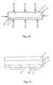
- a so-called selective emitter structure is provided according to the invention in the n-doping.
- the areally very small proportion under the front-side contact is provided with a high n-type doping, while the other areas are provided with a low n-type doping in order to ensure high blue sensitivity.
- n + -layer is therefore divided into two areas.
- the other, by area, minute portion of the wafer surface under the metallization (front-side contact) is heavily doped with phosphorus to ensure low contact resistance.
- the use of a screen-printing paste with an oxide-etching component also allows a cost-effective production of the selective emitter layer by simple structuring of the oxide layer.
- the invention therefore provides an inexpensive method of manufacturing a solar cell having a selective emitter layer.
- this selective emitter structure in the above-described structure of a crystalline silicon solar cell is a masking required, which can be realized for example by a structured oxide layer.
- this oxide layer must be produced in a process step that is specifically required for this purpose.
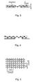
- the method according to the invention comprises a step for structuring an oxide layer applied to a carrier material.
- a screen-printing paste containing an oxide-etching component is printed on the oxide layer by a printing stencil according to the screen-printing method, and the screen-printing paste printed on is removed again after a predetermined exposure time.
- the screen printing method known per se is used to structure an oxide layer applied to a carrier material.
- the screen printing paste is provided with a oxidatzenden component. On all areas that are printed with the paste, the oxide is etched, on non-printed surface areas, however, the oxide is retained.
- the etching process is terminated by washing the silicon wafer in water or a suitable solvent.
- This process comes without photo-resist masks with the associated process steps or consuming Laser devices for structuring, but only requires a screen printing device.
- the process is therefore automatable and suitable for the cost-effective production of large quantities on an industrial scale.
- the oxide-etching component consists of hydrofluoric acid (HP) and / or of ammonium fluoride (NH 4 F) and / or of ammonium hydrogen fluoride (NH 4 HF 2 ).
- Hydrofluoric acid is a waste solution of hydrogen fluoride, HF.
- Commercially available hydrofluoric acid contains about 40% by weight HF and dissolves quartz and silicates.
- Hydrofluoric acid (HF) and / or ammonium fluoride (NH 4 F) and / or ammonium hydrogenfluoride (NH 4 HF 2 ) can therefore be used for etching glass and metals and in particular for etching silicon oxide.
- the oxide-etching component has a proportion of 10-20% by volume of the screen printing paste. It has been shown that with this proportion the exposure time is particularly well controllable. Depending on the thickness of the oxide layer, the exposure time is for example between 30 s and 2 min.
- the n-type doping is introduced by a phosphorus doping.
- the phosphorus glass (POCl 3 ) formed during the introduction of the phosphorus doping is preferably removed again in a subsequent etching step.
- the front side is contacted with a silver screen printing paste.
- Another problem is the contacting of the back of a solar cell.
- silicon For the screen printing contact of the solar cell back side, silicon must be connected to Ag with a basic doping of 1.5E16 atoms / cm 3 . This is only possible with a high contact resistance, which, however, severely affects the fill factor of the solar cell.
- the doping of the silicon on the back side of the wafer In order to reduce the contact resistance, the doping of the silicon on the back side of the wafer must be increased to within the range of about 10E19 atoms / cm 3 . There are different methods for this.
- the doping of the backside is created by an admixture of aluminum into the Ag screen printing paste.
- Aluminum forms an alloy with silicon already at approx. 577 ° C.
- the aluminum content of the Ag paste forms a melt with the silicon at temperatures above approximately 577 ° C.
- the melt recrystallizes, with the solidified silicon being doped with aluminum up to the solubility limit in the range of 10E19 atoms / cm 3 . At this doping concentration, silicon with low contact resistance can be contacted with Ag.
- Solar cells with back surface field represent another class.
- BSF back surface field
- Boron is also suitable for generating a p-doping.
- a corresponding back-surface field can be generated by gas diffusion of a corresponding volatile or gaseous boron compound, by applying a boron-containing silicon layer on the back or by applying a liquid dopant-containing solution.
- all-round diffusion is always observed at the temperatures required for driving in the doping, which is not masked by masking must be prevented to be doped solar cell areas.
- the methodically easy to produce p + doping with aluminum has the disadvantage of increased susceptibility to corrosion. Over time, aluminum-containing layer areas may degrade and peel off, which may damage the back side contacts and reduce solar cell performance.
- a solution to this problem is known from DE 195 08 712 C2.
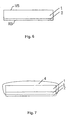
- the basic idea here is to generate the p + doping of the back-surface field by driving out boron from a boron-containing diffusion source layer. The unwanted doping of edges and front side of the wafer is prevented by the expulsion in an oxygen-containing atmosphere at high temperatures of 900 to 1200 ° C is made. Under these conditions, an oxide layer immediately forms on the edges and front side of the wafer, which mask serves to prevent unwanted doping at these points. After driving, both the oxide and the Diffusion source layer can be removed by a simple etching step.
- this oxide layer which forms anyway in the production of the back-surface field for masking the front side in the production of a selective emitter layer.
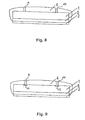
- a further solution according to the invention therefore consists in a method for producing a solar cell with a selective emitter layer on the light incidence side according to the invention described hereinbefore, wherein a back-surface field is produced on the rear side by forming on the p-side before generating the oxide layer.
- doped silicon wafers, a diffusion source layer containing boron as a dopant is deposited on the back side of the silicon wafer, and wherein the silicon wafer is treated in an oxygen-containing atmosphere at a temperature of 900 to 1200 ° C to produce the oxide layer and for driving the dopant.
- the diffusion source layer is removed prior to introduction of the n-doping which is weak over the whole area.
- n-doping is separated at the edge of the wafer.
- a back contact is applied to the back.
- the known per se method for producing a BSF field from DE 195 08 712 C2 can therefore be combined particularly advantageously with the patterning of an oxide layer according to the invention, since the oxide layer forms for masking when driving in the BSF doping, without a further process step is required.
- the generation of the back-surface field (BSF) takes place before the generation of the semiconductor junction, that is to say before the diffusion of phosphorus on the front side of the solar cell.
- the selected high temperatures provide a deep drift of boron doping. This is then also to all
Description
- Die Erfindung betrifft eine Solarzelle und ein Verfahren zu ihrer Herstellung.
- Eine kristalline Silizium-Solarzelle besteht üblicherweise aus einem p-leitenden Substrat, in das auf der Vorderseite eine homogen dicke Schicht einer n-leitenden Substanz, beispielsweise Phosphor, eindiffundiert wird. Auf der Vorder- und der Rückseite des Wafers wird zur Ableitung des unter Lichteinfall erzeugten Stroms eine metallisch leitende Kontaktierung aufgebracht. Im Hinblick auf eine kostengünstige und massenfertigungstaugliche Herstellungsweise wird die Kontaktierung üblicherweise mittels der Siebdrucktechnik erzeugt.
- In dem USA Patent Nr. 5 899 704 ist eine Solarzelle nach dem Stand der Technik und ein Verfahren zu ihrer Herstellung beschrieben. Die Lichteinfallseite eines p-dotierten Silizium-Wafer ist mit einer Emitterschicht mit einer hohen n-Dotierung (n+ -Dotierung) versehen, auf welcher Kontakte angebracht sind. Auf der Rückseite wird ein sogenanntes Back-Surface-Field erzeugt. Das bekannte Verfahren umfasst die Schritte
- Bereitstellen eines p-dotierten Silizium-Wafers mit einer Lichteinfallseite und einer Rückseite;
- Erzeugen einer Oxidschicht auf dem p-dotierten Silizium-Wafer;
- Aufbringen einer Diffusionsquellschicht, die Bor als Dotierstoff enthält, auf der Rückseite des Silizium-Wafers, wobei das Silizium-Wafer in einer Sauerstoff enthaltenden Atmosphäre bei einer Temperatur von 900 bis 1200°C behandelt wird zum Erzeugen der Oxidschicht und zum Eintreiben des Dotierstoffs;
- Entfernen der Oxidschicht;
- Einbringen einer ganzflächig hohen n-Dotierung auf der Lichteinfallseite und der Rückseite; und
- Kontaktierung der Lichteinfallseite und der Rückseite.
- Bei der Höhe der n-Dotierung müssen zwei an sich entgegengesetzte Randbedingungen in Einklang gebracht werden.
- Dokument US-A 5,894,853 beschreibt ein Verfahren zur Strukturierung einer Oxidschicht. Dokument JP 09191118 beschreibt ein Verfahren zur Herstellung einer Solarzelle die eine Schicht mit organischem Ti enthält.
- Zur Anwendung der Siebdrucktechnik für den Vorderseitenkontakt ist es wichtig, eine ausreichend hohe n-Dotierung vorzusehen. Ist die Dotierung des Siliziums zu niedrig, so wird der Übergangswiderstand zwischen dem Silizium und der Kontaktierung zu hoch. Dies hätte zur Folge, dass der Serienwiderstand der Solarzelle ansteigt, was dann zu einem sinkenden Füllfaktor der Hellkennlinie der Solarzelle führt. Auf der anderen Seite führt eine zu hohe n-Dotierung zu einer Erniedrigung der Blauempfindlichkeit der Solarzelle, was eine frühzeitige Rekombination von Ladungsträgern und damit eine Absinkung des Wirkungsgrads zur Folge hätte.
- Bei einer industriell nach dem Stand der Technik hergestellten Solarzelle wird die Vorderseite mit Siebdrucktechnik kontaktiert. Dies erfordert eine Dicke der diffundierten n-Schicht von ca. 0.3 µm mit einer Phosphor-Oberflächenkonzentration im Bereich von 10E20 Atomen/cm3. Durch die Tiefe und die Oberflächenkonzentration der n+-Schicht wird auch ihre Empfindlichkeit im kurzwelligen Teil des eingestrahlten Sonnenspektrums bestimmt. Soll die Blauempfindlichkeit weiter gesteigert werden, d.h. die Kurzschlussstromdicht erhöht werden, so müssen die Eindringtiefe und die Oberflächenkonzentration des Phosphors der n+-Schicht erniedrigt werden. Das hat dann zur Folge, dass der Kontaktwiderstand zwischen der Ag-Metallisierung und der n-dotierten Siliziumschicht ansteigt, was sich dann wiederum in einem sinkenden Füllfaktor der Hellkennlinie der Solarzelle und damit durch abnehmende Effizienz äußert.
- Ein Weg, bei abnehmender Phosphor-Oberflächenkonzentration einen geringen Übergangswiderstand zwischen dem Silizium und der Metallkontaktierung zu gewährleisten, besteht in der Verwendung von Zwischenschichten von Metallen mit niedrigen Barrierenhöhen, z.B. Nickel oder Titan. Das bedeutet jedoch auch den Übergang zu anderen Metallisierungstechnologien wie z.B. der stromlosen Metallabscheidung oder der Aufdampftechnik. Diese Verfahren sind allerdings nicht massenfertigungstauglich und außerdem mit deutlich höheren Fertigungskosten belastet.
- Aufgabe der vorliegenden Erfindung ist es eine Solarzelle mit erhöhter Blauempfindlichkeit und ein kostengünstiges Verfahren zu ihrer Herstellung bereitzustellen.
- Diese Aufgabe wird mit dem Verfahren nach dem Patentanspruch 1 gelöst.
- Um die oben beschriebenen beiden entgegengesetzten Randbedingungen in Einklang zu bringen, wird erfindungsgemäß bei der n-Dotierung eine sogenannte selektive Emitterstruktur vorgesehen. Hierbei wird der flächenmäßig nur sehr kleine Anteil unter der Vorderseitenkontaktierung mit einer hohen n-Dotierung versehen, während die anderen Bereiche mit einer niedrigen n-Dotierung versehen werden, um eine hohe Blauempfindlichkeit zu gewährleisten.
- Erfindungsgemäß wird die n+-Schicht daher in zwei Bereiche aufgeteilt. Der eine, flächenmäßig weit überwiegende Anteil der Waferoberfläche zwischen den metallisierten Bereichen (Vorderseitenkontaktierung), wird nur schwach mit Phosphor dotiert, um eine hohe Blauempfindlichkeit zu gewährleisten.
- Der andere, flächenmäßig nur sehr kleine Anteil der Waferoberfläche unter der Metallisierung (Vorderseitenkontaktierung) wird stark mit Phosphor dotiert, um einen niedrigen Kontaktwiderstand sicherzustellen. Die Verwendung einer Siebdruckpaste mit einer oxidätzenden Komponente ermöglicht auch hier eine kostengünstige Fertigung der selektiven Emitterschicht durch einfache Strukturierung der Oxidschicht.
- Die Erfindung stellt daher ein kostengünstiges Verfahren zum Herstellen einer Solarzelle mit einer selektiven Emitterschicht bereit.
- Um diese selektive Emitterstruktur in den oben beschriebenen Aufbau einer kristallinen Silizium-Solarzelle zu integrieren, ist eine Maskierung erforderlich, die beispielsweise durch eine strukturierte Oxidschicht realisiert werden kann. Diese Oxidschicht muss allerdings in einem eigens dafür erforderlichen Prozessschritt erzeugt werden.
- Es ist bekannt, Oxidschichten nach der photolithographischen Methode oder mit Laserstrahlen zu strukturieren. Diese Verfahren sind allerdings verhältnismäßig kostenaufwendig und daher für eine Anwendung im Low-Cost Solarzellenbereich nicht geeignet.
- Das erfindungsgemäße Verfahren umfasst einen Schritt zur Strukturierung einer auf einem Trägermaterial aufgebrachten Oxidschicht. Dazu wird nach dem Siebdruckverfahren eine Siebdruckpaste, die eine oxidätzende Komponente enthält, durch eine Druckschablone auf die Oxidschicht gedruckt und die aufgedruckte Siebdruckpaste nach einer vorgegebenen Einwirkungszeit wieder entfernt.
- Erfindungsgemäß wird also das an sich bekannte Siebdruckverfahren dazu verwendet, um eine auf einem Trägermaterial aufgebrachte Oxidschicht zu strukturieren. Hierzu wird die Siebdruckpaste mit einer oxidatzenden Komponente versehen. Auf allen Flächenbereichen, die mit der Paste bedruckt werden, wird das Oxid geätzt, auf nicht-bedruckten Flächenbereichen bleibt das Oxid dagegen erhalten.
- Der Ätzprozess wird durch Waschen der Siliziumscheibe in Wasser bzw. einem geeigneten Lösemittel beendet. Dieser Prozess kommt also ohne Photo-Resistmasken mit den zugehörigen Prozessschritten oder aufwendigen Lasergeräten zur Strukturierung aus, sondern benötigt lediglich eine Siebdruckvorrichtung. Der Prozess ist daher automatisierbar und für die kostengünstige Produktion von großen Stückzahlen im industriellen Maßstab geeignet.
- Nach einer bevorzugten Ausführungsform besteht die oxidätzende Komponente aus Flusssäure (HP) und/oder aus Ammoniumfluorid (NH4F) und/oder aus Ammoniumhydrogenfluorid (NH4HF2). Flusssäure ist eine wäserige Lösung von Fluorwasserstoff, HF. Handelsübliche Flusssäure enthält etwa 40 Gew.-% HF und löst Quarz und Silicate. Flusssäure (HF) und/oder aus Ammoniumfluorid (NH4F) und/oder Ammoniumhydrogenfluorid (NH4HF2) können daher zum Ätzen von Glas und Metallen und insbesondere zum Ätzen von Siliziumoxid verwendet werden.
- Nach einer weiteren bevorzugten Ausführungsform ist vorgesehen, dass die oxidätzende Komponente einen Anteil von 10 - 20 Volumenprozent an der Siebdruckpaste aufweist. Es hat sich gezeigt, dass mit diesem Anteil die Einwirkzeit besonders gut steuerbar ist. Je nach Dicke der Oxidschicht beträgt die Einwirkzeit beispielsweise zwischen 30 s und 2 min.
- Nach einer bevorzugten Ausführungsform wird die n-Dotierung durch eine Phosphor-Dotierung eingebracht. Das beim Einbringen der Phosphor-Dotierung entstehende Phosphorglas (POCl3) wird vorzugsweise in einem nachfolgenden Ätzschritt wieder entfernt.
- Nach einer weiteren bevorzugten Ausführungsform wird die Vorderseite mit einer Silbersiebdruckpaste kontaktiert.
- Ein weiteres Problem ist die Kontaktierung der Rückseite einer Solarzelle. Bei der Siebdruckkontaktierung der Solarzellenrückseite muss Silizium mit einer Grunddotierung um 1.5E16 Atomen/cm3 mit Ag verbunden werden. Dies gelingt nur mit einem hohen Übergangswiderstand, der allerdings den Füllfaktor der Solarzelle stark beeinträchtigt. Um den Übergangswiderstand zu reduzieren, muss die Dotierung des Siliziums auf der Waferrückseite in den Bereich von ca. 10E19 Atomen/cm3 angehoben werden. Dazu existieren unterschiedliche Verfahren.
- Bei Solarzellen ohne Back Surface Field (BSF) wird die Dotierung der Rückseite durch eine Beimischung von Aluminium in die Ag-Siebdruckpaste erzeugt. Aluminium bildet mit Silizium schon bei ca. 577°C eine Legierung. Bei Einbrennen der Metallisierung bildet der Aluminiumanteil der Ag-Paste bei Temperaturen oberhalb ca. 577°C mit dem Silizium eine Schmelze. Bei Abkühlung nach dem Einbrennen rekristallisiert die Schmelze, wobei das verfestigte Silizium bis zur Löslichkeitsgrenze im Bereich von lOE19 Atomen/cm3 mit Aluminium dotiert wird. Bei dieser Dotierungskonzentration kann Silizium mit niedrigem Übergangswiderstand mit Ag kontaktiert werden.
- Eine andere Klasse stellen die Solarzellen mit Back Surface Field (BSF) dar. Beim Versuch, die Dicke von Siliziumsolarzellen zu reduzieren, wird ein abnehmender Wirkungsgrad der Solarzelle beobachtet. Dies ist zum einen auf die bei dünnerer Absorptionslänge nicht mehr vollständige Absorption des Sonnenlichts zurückzuführen. Zum anderen werden vermehrt Ladungsträger in der Nähe der Rückseite erzeugt, wobei Minoritätsladungsträger durch Diffusion die Rückelektrode erreichen können und dadurch den durch die Majoritätsladungsträger erzeugten Strom reduzieren. Durch eine hockdotierte Schicht auf der Rückseite ist es möglich, ein der Diffusion der Minoritätsladungsträger entgegenwirkendes Feld, ein sogenanntes Back-Surface-Field (BSF) zu erzeugen. Bei einem SolarzellenaufLau mit einem p-dotierten Solarzellenkörper und einem n+-dotierten Emitter an der Lichteinfalls- bzw. Vorderseite der Solarzelle ist dazu eine p+-Dotierung an der Rückseite erforderlich. Zu deren Erzeugung wird vielfach Aluminium vorgeschlagen, welches sich als dünne Schicht zum Beispiel durch Aufdampfen auf der Rückseite aufbringen und durch einen Temperschritt eintreiben bzw. einlegieren lässt. Möglich ist es auch, die p+-Dotierung durch das Aufbringen aluminiumhaltiger Rückkontakte und entsprechendes Eintreiben des Aluminiums zu erzeugen. Weiterhin ist es möglich, Aluminium aus einer Feststoff- Diffusionsquelle in das Solarzellensubstrat einzudiffundieren. Diese ist allerdings mit dem Nachteil verbunden, dass das Solarzellensubstrat auf beiden Seiten aluminiumdotiert wird, wobei eine p+pp+-Struktur erzeugt wird.
- Auch Bor ist zur Erzeugung einer p-Dotierung geeignet. Ein entsprechendes Back-Surface-Field kann dabei durch Gasdiffusion einer entsprechend flüchtigen bzw. gasförmigen Borverbindung, durch Aufbringen einer borhaltigen Siliziumschicht auf der Rückseite oder durch Aufbringen einer flüssigen dotierstoffhaltigen Lösung erzeugt werden. Bei den für das Eintreiben der Dotierung erforderlichen Temperaturen wird jedoch aufgrund der hohen Flüchtigkeit der Borverbindungen stets eine Rundum-Diffusion beobachtet, die durch eine Maskierung der nicht zu dotierenden Solarzellenbereiche verhindert werden muss.
- Aus der DE 33 40 874 C2 ist ein Verfahren zur Herstellung eines Back-Surface-Fields bekannt, bei dem der entsprechende Dotierstoff aus einer dotierstoffhaltigen Schicht in den Haltleiterkörper eingetrieben wird.
- Die Herstellung eines Back-Surface-Fields durch direkte Diffusion oder durch Eintreiben aus einer Dotierstoffschicht ist aus der US 4,158,591 bekannt. Die nicht zu dotierende Oberfläche des Wafers kann dabei durch Abdecken mit einem zweiten Wafer geschützt werden.
- Die verfahrensmäßig einfach herzustellende p+-Dotierung mit Aluminium hat den Nachteil einer erhöhten Korrosionsanfälligkeit. Im Laufe der Zeit können sich aluminiumhaltige Schichtbereiche zersetzen und ablösen, was zur Beschädigung der Rückseitenkontakte und zur Reduzierung der Solarzellenleistung führen kann. Eine Lösung dieses Problems ist aus DE 195 08 712 C2 bekannt. Die grundlegende Idee ist hier, die p+-Dotierung des Back-Surface-Fields durch Austreiben von Bor aus einer borhaltigen Diffusionsquellschicht zu erzeugen. Die nicht gewünschte Dotierung von Rändern und Vorderseite des Wafers wird verhindert, indem das Austreiben in einer sauerstoffhaltigen Atmosphäre bei hohen Temperaturen von 900 bis 1200°C vorgenommen wird. Unter diesen Bedingungen bildet sich an Rändern und Vorderseite des Wafers sofort eine Oxidschicht aus, die zur Maskierung dient und damit die unerwünschte Dotierung an diesen Stellen verhindert. Nach dem Eintreiben kann sowohl die Oxid- als auch die Diffusionsquellschicht durch einen einfachen Ätzschritt entfernt werden.
- Als weitere Lösung der Erfindung wird nunmehr vorgeschlagen, diese sich ohnehin bildende Oxidschicht bei der Erzeugung des Back-Surface-Fields zur Maskierung der Vorderseite bei der Herstellung einer selektiven Emitterschicht zu nutzen.
- Eine weitere erfindungsgemäße Lösung besteht daher in einem Verfahren zum Erzeugen einer Solarzelle mit einer selektiven Emitterschicht auf der Lichteinfallseite entspreched der hiervor beschriebenen Erfindung, wobei ein Back-Surface-Field auf der Rückseite dadurch erzeugt wird, dass vor dem Erzeugen der Oxidschicht auf dem p-dotierten Silizium-Wafer eine Diffusionsquellschicht, die Bor als Dotierstoff enthält, auf der Rückseite des Silizium-Wafers aufgebracht wird, und wobei das Silizium-Wafer in einer Sauerstoff enthaltenden Atmosphäre bei einer Temperatur von 900 bis 1200°C behandelt wird zum Erzeugen der Oxidschicht und zum Eintreiben des Dotierstoffs.
- Nach einer bevorzugten Ausführungsform wird die Diffusionsquellschicht vor dem Einbringen der ganzflächig schwachen n-Dotierung entfernt.
- Nach einer weiteren bevorzugten Ausführungsform wird n-Dotierung am Rand des Wafers aufgetrennt.
- Nach einer weiteren bevorzugten Ausführungsform wird ein Rückkontakt auf der Rückseite aufgebracht.
- Das an sich bekannte Verfahren zur Herstellung eines BSF-Feldes aus der DE 195 08 712 C2 kann also besonders vorteilhaft mit der erfindungsgemäßen Strukturierung einer Oxidschicht kombiniert werden, da sich die Oxidschicht zur Maskierung beim Eintreiben der BSF-Dotierung ausbildet, ohne dass ein weiterer Prozessschritt erforderlich ist.
- Ansonsten ergeben sich alle weiteren Vorteile des aus der DE 195 08 712 C2 bekannten Verfahrens.
- Beispielsweise ist zu beachten, dass die Erzeugung des Back-Surface-Fields (BSF) vor der Erzeugung des Halbleiterübergangs erfolgt, also vor der Eindiffusion von Phosphor auf der Vorderseite der Solarzelle. Die gewählten hohen Temperaturen sorgen für ein tiefes Eintreiben der Bordotierung. Diese ist dann auch gegenüber sämtlichen
Claims (22)
- Verfahren zum Herstellen einer Solarzelle mit einer selektiven Emitterschicht auf der Lichteinfallseite, umfassend die folgenden Schritte:- Bereitstellen eines p-dotierten Silizium-Wafers mit einer Lichteinfallseite und einer Rückseite;- Erzeugen einer Oxidschicht auf der Lichteinfallseite des p-dotierten Silizium-Wafers;- Strukturierung der Oxidschicht zur Ausbildung strukturierter Bereiche, indem mittels Siebdruck eine Siebdruckpaste, die eine oxidätzende Komponente enthält, durch eine Druckschablone auf die Oxidschicht gedruckt wird, und wobei die aufgedruckte Siebdruckpaste nach einer vorgegebenen Einwirkungszeit wieder entfernt wird;- Einbringen einer selektiven hohen n-Dotierung in den strukturierten Bereichen zur Ausbildung der selektiven Emitterschicht;- Entfernen der Oxidschicht;- Einbringen einer ganzflächig schwachen n-Dotierung über die selektiven hohen n-Dotierungen; und- Kontaktierung der Lichteinfallseite in Bereichen der selektiven hohen n-Dotierung.
- Verfahren nach Anspruch 1, dadurch gekennzeichnet, dass die oxidätzende Komponente aus Flusssäure (HF) und/oder aus Ammoniumfluorid (NH4F) und/oder aus Ammoniumhydrogenfluorid (NH4HF2) besteht.
- Verfahren nach einem der Ansprüche 1-2, dadurch gekennzeichnet, dass die oxidätzende Komponente einen Anteil von 10 - 20 Volumenprozent an der Siebdruckpaste aufweist.
- Verfahren nach einem der Ansprüche 1-3, dadurch gekennzeichnet, dass die Einwirkungszeit zwischen 30 s und 2 min beträgt.
- Verfahren nach einem der Ansprüche 1-4, wobei die Kontaktierung der Lichteinfallseite mittels Siebdruck vorgenommen wird.
- Verfahren nach einem der Ansprüche 1-5, dadurch gekennzeichnet, dass die n-Dotierung durch eine Phosphor-Dotierung eingebracht wird.
- Verfahren nach einem der Ansprüche 1-6, dadurch gekennzeichnet, dass das beim Einbringen der Phosphor-Dotierung entstehende Phosphorglas (POCl3) in einem nachfolgenden Ätzschritt wieder entfernt wird.
- Verfahren nach einem der Ansprüche 1-7, dadurch gekennzeichnet, dass die Vorderseite mit einer Silbersiebdruckpaste kontaktiert wird.
- Verfahren nach einem der Ansprüche 1-8, wobei weiterhin ein Back-Surface-Field auf der Rückseite des Silizium-Wafers erzeugt wird, indem vor dem Erzeugen der Oxidschicht auf dem p-dotierten Silizium-Wafer eine Diffusionsquellschicht, die Bor als Dotierstoff enthält, auf der Rückseite des Silizium-Wafers aufgebracht wird, und wobei das Silizium-Wafer in einer Sauerstoff enthaltenden Atmosphäre bei einer Temperatur von 900 bis 1200°C behandelt wird zum Erzeugen der Oxidschicht und zum Eintreiben des Dotierstoffs.
- Verfahren nach Anspruch 9, wobei die Diffusionsquellschicht vor dem Einbringen der ganzflächig schwachen n-Dotierung entfernt wird.
- Verfahren nach Anspruch 9 oder 10, weiterhin umfassend den Schritt der Auftrennung der n-Dotierung am Rand des Wafers.
- Verfahren nach einem der Ansprüche 9-11, wobei ein Rückkontakt auf der Rückseite aufgebracht wird.
- Verfahren nach einem der Ansprüche 9-12, dadurch gekennzeichnet, dass als Diffusionsquellschicht ein Bordotierlack oder eine Bordotierpaste aufgebracht wird.
- Verfahren nach einem der Ansprüche 9-13, dadurch gekennzeichnet, dass die Diffusionsquellschicht und Oxidschicht durch Ätzen mit HF-Lösung entfernt werden.
- Verfahren nach Anspruch 11, wobei das Auftrennen der n-Dotierung am Rand des Wafers durch Abätzen der Außenränder erfolgt.
- Verfahren nach einem der Ansprüche 9 - 15, dadurch gekennzeichnet, dass die Rückseite mit einer Silbersiebdruckpaste kontaktiert wird, die 1 bis 3 Gewichtsprozent Aluminium enthält.
- Verfahren nach Anspruch 12, wobei die Rückseite in Bereichen derart kontaktiert wird, dass zwischen den von dem Rückkontakt bedeckten Bereichen die Bordotierung von einer flacheren n- Dotierung überkompensiert ist.
- Verfahren nach einem der Ansprüche 9 - 17, dadurch gekennzeichnet, dass eine Antireflexschicht auf der Lichteinfalleeite und eine Passivierungsschicht auf der Rückseite aufgebracht ist.
- Verfahren nach einem der Ansprüche 1-18, wobei zur Strukturierung der Oxidschicht eine Siebdruckpaste mit einem Bindemittel und einer oxidätzenden Komponente verwendet wird.
- Verfahren nach einem der Ansprüche 1-19, wobei zur Strukturierung der Oxidschicht eine Siebdruckpaste verwendet wird mit einer Viskosität zwischen 10 und 500 Pa s, vorzugsweise zwischen 50 und 200 Pa s.
- Verfahren nach Anspruch 19, wobei das Bindemittel aus Tapetenkleister besteht.
- Verfahren nach Anspruch 19, wobei das Bindemittel aus einem Epoxidharz besteht.
Applications Claiming Priority (3)
| Application Number | Priority Date | Filing Date | Title |
|---|---|---|---|
| DE10104726 | 2001-02-02 | ||
| DE10104726A DE10104726A1 (de) | 2001-02-02 | 2001-02-02 | Verfahren zur Strukturierung einer auf einem Trägermaterial aufgebrachten Oxidschicht |
| PCT/EP2002/001096 WO2002061854A2 (de) | 2001-02-02 | 2002-02-01 | Verfahren zur strukturierung einer auf einem trägermaterial aufgebrachten oxidschicht |
Publications (2)
| Publication Number | Publication Date |
|---|---|
| EP1390987A2 EP1390987A2 (de) | 2004-02-25 |
| EP1390987B1 true EP1390987B1 (de) | 2006-11-22 |
Family
ID=7672635
Family Applications (1)
| Application Number | Title | Priority Date | Filing Date |
|---|---|---|---|
| EP02712887A Expired - Lifetime EP1390987B1 (de) | 2001-02-02 | 2002-02-01 | Verfahren zur strukturierung einer auf einem trägermaterial aufgebrachten oxidschicht |
Country Status (8)
| Country | Link |
|---|---|
| US (1) | US7129109B2 (de) |
| EP (1) | EP1390987B1 (de) |
| JP (1) | JP2004520713A (de) |
| CN (1) | CN1316638C (de) |
| AT (1) | ATE346382T1 (de) |
| AU (1) | AU2002244699B2 (de) |
| DE (2) | DE10104726A1 (de) |
| WO (1) | WO2002061854A2 (de) |
Cited By (1)
| Publication number | Priority date | Publication date | Assignee | Title |
|---|---|---|---|---|
| US7951637B2 (en) | 2008-08-27 | 2011-05-31 | Applied Materials, Inc. | Back contact solar cells using printed dielectric barrier |
Families Citing this family (92)
| Publication number | Priority date | Publication date | Assignee | Title |
|---|---|---|---|---|
| WO2003047005A2 (en) * | 2001-11-26 | 2003-06-05 | Shell Solar Gmbh | Manufacturing a solar cell with backside contacts |
| JP4845742B2 (ja) * | 2004-02-13 | 2011-12-28 | シェル ゾーラー ゲーエムベーハー | ウエハに液状ドーパント溶液を塗布するための機器 |
| JP4582538B2 (ja) * | 2004-10-21 | 2010-11-17 | Okiセミコンダクタ株式会社 | 導電性インクの印刷方法及び導電性インクの印刷装置 |
| KR101188425B1 (ko) * | 2005-08-24 | 2012-10-05 | 엘지디스플레이 주식회사 | 식각 테이프 및 이를 이용한 액정 표시 장치용 어레이기판의 제조 방법 |
| KR20080104130A (ko) * | 2006-02-28 | 2008-12-01 | 시바 홀딩 인코포레이티드 | 항균성 화합물 |
| DE502006005702D1 (de) * | 2006-05-04 | 2010-01-28 | Elektrobit Wireless Comm Ltd | Verfahren zur Inbetriebnahme eines RFID-Netzwerks |
| US9105776B2 (en) | 2006-05-15 | 2015-08-11 | Stion Corporation | Method and structure for thin film photovoltaic materials using semiconductor materials |
| US8017860B2 (en) | 2006-05-15 | 2011-09-13 | Stion Corporation | Method and structure for thin film photovoltaic materials using bulk semiconductor materials |
| US20080014661A1 (en) * | 2006-07-11 | 2008-01-17 | Michael Haag | Method for the manufacture of solar panels and special transport carrier |
| FR2906405B1 (fr) * | 2006-09-22 | 2008-12-19 | Commissariat Energie Atomique | Procede de realisation de regions dopees dans un substrat et de cellule photovoltaique |
| CN101755237B (zh) * | 2006-12-05 | 2014-04-09 | 纳诺泰拉公司 | 使表面形成图案的方法 |
| US8608972B2 (en) * | 2006-12-05 | 2013-12-17 | Nano Terra Inc. | Method for patterning a surface |
| US20080300918A1 (en) * | 2007-05-29 | 2008-12-04 | Commercenet Consortium, Inc. | System and method for facilitating hospital scheduling and support |
| US8071179B2 (en) | 2007-06-29 | 2011-12-06 | Stion Corporation | Methods for infusing one or more materials into nano-voids if nanoporous or nanostructured materials |
| US7919400B2 (en) | 2007-07-10 | 2011-04-05 | Stion Corporation | Methods for doping nanostructured materials and nanostructured thin films |
| US8058092B2 (en) | 2007-09-28 | 2011-11-15 | Stion Corporation | Method and material for processing iron disilicide for photovoltaic application |
| US8759671B2 (en) | 2007-09-28 | 2014-06-24 | Stion Corporation | Thin film metal oxide bearing semiconductor material for single junction solar cell devices |
| US8287942B1 (en) | 2007-09-28 | 2012-10-16 | Stion Corporation | Method for manufacture of semiconductor bearing thin film material |
| US8614396B2 (en) | 2007-09-28 | 2013-12-24 | Stion Corporation | Method and material for purifying iron disilicide for photovoltaic application |
| US8187434B1 (en) | 2007-11-14 | 2012-05-29 | Stion Corporation | Method and system for large scale manufacture of thin film photovoltaic devices using single-chamber configuration |
| US7888168B2 (en) | 2007-11-19 | 2011-02-15 | Applied Materials, Inc. | Solar cell contact formation process using a patterned etchant material |
| US20090139568A1 (en) * | 2007-11-19 | 2009-06-04 | Applied Materials, Inc. | Crystalline Solar Cell Metallization Methods |
| EP2252467A1 (de) * | 2008-02-06 | 2010-11-24 | Nano Terra Inc. | Schablonen mit entfernbaren trägern zur bildung von merkmalen mit einer grösse im mikrometerbereich auf oberflächen und verfahren zur herstellung und verwendung derselben |
| KR101104606B1 (ko) * | 2008-02-19 | 2012-01-12 | 주식회사 엘지화학 | 태양전지용 선택적 에미터의 제조방법 및 그에 사용되는마스크 패턴 제조용 페이스트. |
| US8440903B1 (en) | 2008-02-21 | 2013-05-14 | Stion Corporation | Method and structure for forming module using a powder coating and thermal treatment process |
| US8772078B1 (en) | 2008-03-03 | 2014-07-08 | Stion Corporation | Method and system for laser separation for exclusion region of multi-junction photovoltaic materials |
| US8075723B1 (en) | 2008-03-03 | 2011-12-13 | Stion Corporation | Laser separation method for manufacture of unit cells for thin film photovoltaic materials |
| US8461032B2 (en) * | 2008-03-05 | 2013-06-11 | Varian Semiconductor Equipment Associates, Inc. | Use of dopants with different diffusivities for solar cell manufacture |
| US20090239363A1 (en) * | 2008-03-24 | 2009-09-24 | Honeywell International, Inc. | Methods for forming doped regions in semiconductor substrates using non-contact printing processes and dopant-comprising inks for forming such doped regions using non-contact printing processes |
| US7939454B1 (en) | 2008-05-31 | 2011-05-10 | Stion Corporation | Module and lamination process for multijunction cells |
| US8642138B2 (en) | 2008-06-11 | 2014-02-04 | Stion Corporation | Processing method for cleaning sulfur entities of contact regions |
| US9087943B2 (en) | 2008-06-25 | 2015-07-21 | Stion Corporation | High efficiency photovoltaic cell and manufacturing method free of metal disulfide barrier material |
| US8003432B2 (en) | 2008-06-25 | 2011-08-23 | Stion Corporation | Consumable adhesive layer for thin film photovoltaic material |
| US8183081B2 (en) | 2008-07-16 | 2012-05-22 | Applied Materials, Inc. | Hybrid heterojunction solar cell fabrication using a metal layer mask |
| US8207008B1 (en) | 2008-08-01 | 2012-06-26 | Stion Corporation | Affixing method and solar decal device using a thin film photovoltaic |
| US20100035422A1 (en) * | 2008-08-06 | 2010-02-11 | Honeywell International, Inc. | Methods for forming doped regions in a semiconductor material |
| US8053867B2 (en) * | 2008-08-20 | 2011-11-08 | Honeywell International Inc. | Phosphorous-comprising dopants and methods for forming phosphorous-doped regions in semiconductor substrates using phosphorous-comprising dopants |
| US7855089B2 (en) | 2008-09-10 | 2010-12-21 | Stion Corporation | Application specific solar cell and method for manufacture using thin film photovoltaic materials |
| US8026122B1 (en) | 2008-09-29 | 2011-09-27 | Stion Corporation | Metal species surface treatment of thin film photovoltaic cell and manufacturing method |
| US8394662B1 (en) | 2008-09-29 | 2013-03-12 | Stion Corporation | Chloride species surface treatment of thin film photovoltaic cell and manufacturing method |
| US8236597B1 (en) | 2008-09-29 | 2012-08-07 | Stion Corporation | Bulk metal species treatment of thin film photovoltaic cell and manufacturing method |
| US8476104B1 (en) | 2008-09-29 | 2013-07-02 | Stion Corporation | Sodium species surface treatment of thin film photovoltaic cell and manufacturing method |
| US8008112B1 (en) | 2008-09-29 | 2011-08-30 | Stion Corporation | Bulk chloride species treatment of thin film photovoltaic cell and manufacturing method |
| US8008110B1 (en) | 2008-09-29 | 2011-08-30 | Stion Corporation | Bulk sodium species treatment of thin film photovoltaic cell and manufacturing method |
| US8501521B1 (en) | 2008-09-29 | 2013-08-06 | Stion Corporation | Copper species surface treatment of thin film photovoltaic cell and manufacturing method |
| US7951696B2 (en) * | 2008-09-30 | 2011-05-31 | Honeywell International Inc. | Methods for simultaneously forming N-type and P-type doped regions using non-contact printing processes |
| US8425739B1 (en) | 2008-09-30 | 2013-04-23 | Stion Corporation | In chamber sodium doping process and system for large scale cigs based thin film photovoltaic materials |
| US8383450B2 (en) | 2008-09-30 | 2013-02-26 | Stion Corporation | Large scale chemical bath system and method for cadmium sulfide processing of thin film photovoltaic materials |
| US7910399B1 (en) | 2008-09-30 | 2011-03-22 | Stion Corporation | Thermal management and method for large scale processing of CIS and/or CIGS based thin films overlying glass substrates |
| US7863074B2 (en) | 2008-09-30 | 2011-01-04 | Stion Corporation | Patterning electrode materials free from berm structures for thin film photovoltaic cells |
| US7947524B2 (en) | 2008-09-30 | 2011-05-24 | Stion Corporation | Humidity control and method for thin film photovoltaic materials |
| US8741689B2 (en) | 2008-10-01 | 2014-06-03 | Stion Corporation | Thermal pre-treatment process for soda lime glass substrate for thin film photovoltaic materials |
| US20110018103A1 (en) | 2008-10-02 | 2011-01-27 | Stion Corporation | System and method for transferring substrates in large scale processing of cigs and/or cis devices |
| US8435826B1 (en) | 2008-10-06 | 2013-05-07 | Stion Corporation | Bulk sulfide species treatment of thin film photovoltaic cell and manufacturing method |
| US8003430B1 (en) | 2008-10-06 | 2011-08-23 | Stion Corporation | Sulfide species treatment of thin film photovoltaic cell and manufacturing method |
| USD625695S1 (en) | 2008-10-14 | 2010-10-19 | Stion Corporation | Patterned thin film photovoltaic module |
| US8168463B2 (en) | 2008-10-17 | 2012-05-01 | Stion Corporation | Zinc oxide film method and structure for CIGS cell |
| DE102008056456A1 (de) * | 2008-11-07 | 2010-06-17 | Centrotherm Photovoltaics Technology Gmbh | Verfahren zur Herstellung einer Solarzelle mit einer zweistufigen Dotierung |
| US8344243B2 (en) | 2008-11-20 | 2013-01-01 | Stion Corporation | Method and structure for thin film photovoltaic cell using similar material junction |
| US7820532B2 (en) * | 2008-12-29 | 2010-10-26 | Honeywell International Inc. | Methods for simultaneously forming doped regions having different conductivity-determining type element profiles |
| US8518170B2 (en) | 2008-12-29 | 2013-08-27 | Honeywell International Inc. | Boron-comprising inks for forming boron-doped regions in semiconductor substrates using non-contact printing processes and methods for fabricating such boron-comprising inks |
| US7858427B2 (en) * | 2009-03-03 | 2010-12-28 | Applied Materials, Inc. | Crystalline silicon solar cells on low purity substrate |
| USD662040S1 (en) | 2009-06-12 | 2012-06-19 | Stion Corporation | Pin striped thin film solar module for garden lamp |
| USD628332S1 (en) | 2009-06-12 | 2010-11-30 | Stion Corporation | Pin striped thin film solar module for street lamp |
| USD632415S1 (en) | 2009-06-13 | 2011-02-08 | Stion Corporation | Pin striped thin film solar module for cluster lamp |
| USD652262S1 (en) | 2009-06-23 | 2012-01-17 | Stion Corporation | Pin striped thin film solar module for cooler |
| USD662041S1 (en) | 2009-06-23 | 2012-06-19 | Stion Corporation | Pin striped thin film solar module for laptop personal computer |
| US8507786B1 (en) | 2009-06-27 | 2013-08-13 | Stion Corporation | Manufacturing method for patterning CIGS/CIS solar cells |
| USD627696S1 (en) | 2009-07-01 | 2010-11-23 | Stion Corporation | Pin striped thin film solar module for recreational vehicle |
| TW201104822A (en) * | 2009-07-20 | 2011-02-01 | E Ton Solar Tech Co Ltd | Aligning method of patterned electrode in a selective emitter structure |
| US8324089B2 (en) | 2009-07-23 | 2012-12-04 | Honeywell International Inc. | Compositions for forming doped regions in semiconductor substrates, methods for fabricating such compositions, and methods for forming doped regions using such compositions |
| US8398772B1 (en) | 2009-08-18 | 2013-03-19 | Stion Corporation | Method and structure for processing thin film PV cells with improved temperature uniformity |
| US8809096B1 (en) | 2009-10-22 | 2014-08-19 | Stion Corporation | Bell jar extraction tool method and apparatus for thin film photovoltaic materials |
| CN102088042A (zh) * | 2009-12-02 | 2011-06-08 | 上海交大泰阳绿色能源有限公司 | 一种高效率晶体硅太阳能电池用浆料的制备方法和浆料 |
| US8859880B2 (en) | 2010-01-22 | 2014-10-14 | Stion Corporation | Method and structure for tiling industrial thin-film solar devices |
| US8263494B2 (en) | 2010-01-25 | 2012-09-11 | Stion Corporation | Method for improved patterning accuracy for thin film photovoltaic panels |
| US9096930B2 (en) | 2010-03-29 | 2015-08-04 | Stion Corporation | Apparatus for manufacturing thin film photovoltaic devices |
| US8461061B2 (en) | 2010-07-23 | 2013-06-11 | Stion Corporation | Quartz boat method and apparatus for thin film thermal treatment |
| US8628997B2 (en) | 2010-10-01 | 2014-01-14 | Stion Corporation | Method and device for cadmium-free solar cells |
| TWI431797B (zh) | 2010-10-19 | 2014-03-21 | Ind Tech Res Inst | 選擇性射極之太陽能電池及其製作方法 |
| EP2651841A1 (de) * | 2010-12-15 | 2013-10-23 | Sun Chemical Corporation | Bedruckbare ätzmittelzusammensetzungen zum ätzen von transparenten, leitfähigen folien auf silbernanodrahtbasis |
| US8998606B2 (en) | 2011-01-14 | 2015-04-07 | Stion Corporation | Apparatus and method utilizing forced convection for uniform thermal treatment of thin film devices |
| US8728200B1 (en) | 2011-01-14 | 2014-05-20 | Stion Corporation | Method and system for recycling processing gas for selenization of thin film photovoltaic materials |
| US8436445B2 (en) | 2011-08-15 | 2013-05-07 | Stion Corporation | Method of manufacture of sodium doped CIGS/CIGSS absorber layers for high efficiency photovoltaic devices |
| US8629294B2 (en) | 2011-08-25 | 2014-01-14 | Honeywell International Inc. | Borate esters, boron-comprising dopants, and methods of fabricating boron-comprising dopants |
| DE102011084843A1 (de) * | 2011-10-20 | 2013-04-25 | Schott Solar Ag | Verfahren zur galvanischen Emitterkontaktierung eines insbesondere siliciumbasierten Wafers bestimmt für eine Solarzelle |
| US8975170B2 (en) | 2011-10-24 | 2015-03-10 | Honeywell International Inc. | Dopant ink compositions for forming doped regions in semiconductor substrates, and methods for fabricating dopant ink compositions |
| CN104011882A (zh) | 2012-01-12 | 2014-08-27 | 应用材料公司 | 制造太阳能电池装置的方法 |
| CN103400902A (zh) * | 2013-08-14 | 2013-11-20 | 迅力光能(昆山)有限公司 | 一种ito薄膜太阳能电池片及其图案制备方法 |
| WO2015162298A1 (de) | 2014-04-25 | 2015-10-29 | Ceramtec Gmbh | Aluminiumpaste für dickfilmhybride |
| CN104124305A (zh) * | 2014-06-25 | 2014-10-29 | 上饶光电高科技有限公司 | 一种处理晶体硅太阳能电池片串联电阻偏大的方法 |
| DE102022107163A1 (de) | 2022-03-25 | 2023-09-28 | Fraunhofer-Gesellschaft zur Förderung der angewandten Forschung eingetragener Verein | Druckschablone und Druckvorrichtungen zur Ausbildung von Leiterbahnen auf einem Substrat und Verfahren zur Herstellung einer metallischen Kontaktstruktur einer photovoltaischen Solarzelle |
Family Cites Families (34)
| Publication number | Priority date | Publication date | Assignee | Title |
|---|---|---|---|---|
| US2127781A (en) * | 1936-03-12 | 1938-08-23 | Mckay Co | Glass etching |
| US4510276A (en) | 1979-12-13 | 1985-04-09 | Kollmorgen Technologies Corporation | Epoxy resin coating compositions for printed circuit boards |
| US4486466A (en) | 1979-01-12 | 1984-12-04 | Kollmorgen Technologies Corporation | High resolution screen printable resists |
| DE2929589A1 (de) * | 1979-07-04 | 1981-01-22 | Bbc Brown Boveri & Cie | Verfahren zur herstellung eines optisch transparenten und elektrisch leitfaehigen filmmusters |
| US4504607A (en) | 1979-12-13 | 1985-03-12 | Kollmorgen Technologies Corporation | Epoxy resin coating composition for printed circuit boards |
| US4551488A (en) | 1979-12-14 | 1985-11-05 | Kollmorgen Technologies Corporation | Epoxy resin based protective coating composition for printed circuit boards |
| JPS56129394A (en) | 1980-03-14 | 1981-10-09 | Dainippon Screen Mfg | Method of producing through hole of printed board |
| JPS573875A (en) * | 1980-06-11 | 1982-01-09 | Tamura Kaken Kk | Photopolymerizable ink composition |
| DE3136818C2 (de) | 1980-09-19 | 1990-08-02 | Hitachi Chemical Co., Ltd., Tokio/Tokyo | Verwendung eines lichtempfindlichen Gemisches und eines lichtempfindlichen Aufzeichnungsmaterials zur Bildung einer Lötmaske |
| US4752553A (en) | 1982-04-01 | 1988-06-21 | M&T Chemicals Inc. | High resolution solder mask photopolymers for screen coating over circuit traces |
| US4781792A (en) * | 1985-05-07 | 1988-11-01 | Hogan James V | Method for permanently marking glass |
| JPS629680A (ja) | 1985-07-08 | 1987-01-17 | Hitachi Ltd | 太陽電池の製造方法 |
| US4927736A (en) | 1987-07-21 | 1990-05-22 | Hoechst Celanese Corporation | Hydroxy polyimides and high temperature positive photoresists therefrom |
| US4872925A (en) * | 1987-10-29 | 1989-10-10 | Glasstech, Inc. | Photovoltaic cell fabrication method and panel made thereby |
| JP2687751B2 (ja) | 1991-03-18 | 1997-12-08 | 信越化学工業株式会社 | 感光性重合体材料 |
| GB9123684D0 (en) | 1991-11-07 | 1992-01-02 | Bp Solar Ltd | Ohmic contacts |
| KR950002233B1 (ko) * | 1992-08-14 | 1995-03-15 | 김태환 | 유리에칭 조성물과 그를 이용한 유리표면의 에칭 방법 |
| JP3282882B2 (ja) | 1993-05-07 | 2002-05-20 | ナミックス株式会社 | 誘電体保護剤 |
| EP1094527A3 (de) * | 1993-07-29 | 2007-06-20 | Gerhard Dr. Willeke | Flaches Bauelement mit einem Gitternetz von Durchgangslöchern |
| US5554684A (en) | 1993-10-12 | 1996-09-10 | Occidental Chemical Corporation | Forming polyimide coating by screen printing |
| US5856380A (en) * | 1993-12-16 | 1999-01-05 | Ciba Specialty Chemical Corporation | Process for flame-proofing organic polymeric materials |
| US5688366A (en) * | 1994-04-28 | 1997-11-18 | Canon Kabushiki Kaisha | Etching method, method of producing a semiconductor device, and etchant therefor |
| US5457057A (en) * | 1994-06-28 | 1995-10-10 | United Solar Systems Corporation | Photovoltaic module fabrication process |
| JP3057599B2 (ja) * | 1994-07-06 | 2000-06-26 | キヤノン株式会社 | 洗浄装置及び洗浄方法 |
| JP3548246B2 (ja) * | 1994-11-04 | 2004-07-28 | キヤノン株式会社 | 光起電力素子及びその製造方法 |
| JPH08148787A (ja) | 1994-11-21 | 1996-06-07 | Sumitomo Kinzoku Ceramics:Kk | 厚膜ペースト |
| DE19508712C2 (de) | 1995-03-10 | 1997-08-07 | Siemens Solar Gmbh | Solarzelle mit Back-Surface-Field und Verfahren zur Herstellung |
| GB9508879D0 (en) * | 1995-05-02 | 1995-06-21 | Ici Plc | Dye diffusion thermal transfer printing |
| JPH09191118A (ja) * | 1996-01-11 | 1997-07-22 | Shin Etsu Chem Co Ltd | 太陽電池の製造方法 |
| DE69800652T2 (de) | 1997-02-25 | 2001-08-23 | Du Pont | Flexible, flammhemmende fotopolymerisierbare Zusammensetzung zur Beschichtung von Leiterplatten |
| EP0891127A3 (de) | 1997-07-11 | 2000-03-22 | Lexmark International, Inc. | Schutzüberzug eines TAB-Schaltkreises |
| JPH11251612A (ja) * | 1998-03-03 | 1999-09-17 | Canon Inc | 光起電力素子の製造方法 |
| DE19910816A1 (de) | 1999-03-11 | 2000-10-05 | Merck Patent Gmbh | Dotierpasten zur Erzeugung von p,p+ und n,n+ Bereichen in Halbleitern |
| US6451931B1 (en) * | 2000-12-29 | 2002-09-17 | Asahi Denki Kogyo Kabushiki Kaisha | Reaction product of primary and tertiary amine-containing compound, dihydrazide an polyisocyanate |
-
2001
- 2001-02-02 DE DE10104726A patent/DE10104726A1/de not_active Withdrawn
-
2002
- 2002-02-01 WO PCT/EP2002/001096 patent/WO2002061854A2/de active IP Right Grant
- 2002-02-01 JP JP2002561294A patent/JP2004520713A/ja active Pending
- 2002-02-01 AT AT02712887T patent/ATE346382T1/de not_active IP Right Cessation
- 2002-02-01 DE DE50208787T patent/DE50208787D1/de not_active Expired - Lifetime
- 2002-02-01 US US10/470,896 patent/US7129109B2/en not_active Expired - Fee Related
- 2002-02-01 EP EP02712887A patent/EP1390987B1/de not_active Expired - Lifetime
- 2002-02-01 CN CNB028044479A patent/CN1316638C/zh not_active Expired - Fee Related
- 2002-02-01 AU AU2002244699A patent/AU2002244699B2/en not_active Ceased
Cited By (1)
| Publication number | Priority date | Publication date | Assignee | Title |
|---|---|---|---|---|
| US7951637B2 (en) | 2008-08-27 | 2011-05-31 | Applied Materials, Inc. | Back contact solar cells using printed dielectric barrier |
Also Published As
| Publication number | Publication date |
|---|---|
| AU2002244699B2 (en) | 2006-08-31 |
| ATE346382T1 (de) | 2006-12-15 |
| JP2004520713A (ja) | 2004-07-08 |
| DE50208787D1 (de) | 2007-01-04 |
| CN1316638C (zh) | 2007-05-16 |
| US7129109B2 (en) | 2006-10-31 |
| EP1390987A2 (de) | 2004-02-25 |
| WO2002061854A3 (de) | 2003-12-11 |
| DE10104726A1 (de) | 2002-08-08 |
| CN1537334A (zh) | 2004-10-13 |
| WO2002061854A2 (de) | 2002-08-08 |
| US20040110393A1 (en) | 2004-06-10 |
Similar Documents
| Publication | Publication Date | Title |
|---|---|---|
| EP1390987B1 (de) | Verfahren zur strukturierung einer auf einem trägermaterial aufgebrachten oxidschicht | |
| DE69731485T2 (de) | Halbleitervorrichtung mit selektiv diffundierten bereichen | |
| EP0813753B1 (de) | Solarzelle mit back-surface-field und verfahren zur herstellung | |
| DE60221426T2 (de) | SOLARZELLE MIT RÜCKSEITE-KONTAKT und HERSTELLUNGSVERFAHREN dazu | |
| EP0630525B1 (de) | Herstellungsverfahren einer Solarzelle mit kombinierter Metallisierung | |
| EP1977442B1 (de) | Verfahren zur herstellung eines halbleiterbauelements mit unterschiedlich stark dotierten bereichen | |
| EP1435116B1 (de) | Kombinierte ätz- und dotiermedien | |
| EP0905794B1 (de) | Solarzelle und Herstellungsverfahren | |
| DE102009005168A1 (de) | Solarzelle und Verfahren zur Herstellung einer Solarzelle aus einem Siliziumsubstrat | |
| DE112005002592T5 (de) | Rückseitenkontakt-Photovoltaikzellen | |
| DE102011050089B4 (de) | Verfahren zum Herstellen von elektrischen Kontakten an einer Solarzelle, Solarzelle und Verfahren zum Herstellen eines Rückseiten-Kontaktes einer Solarzelle | |
| DE102007036921A1 (de) | Verfahren zur Herstellung von Siliziumsolarzellen | |
| EP2404323A2 (de) | Solarzellen mit rückseitenkontaktierung sowie verfahren zu deren herstellung | |
| EP2494615A2 (de) | Verfahren zur herstellung von solarzellen mit selektivem emitter | |
| EP2561557B1 (de) | Verfahren zur herstellung einer solarzelle | |
| WO2015044122A1 (de) | Verfahren zum herstellen einer photovoltaischen solarzelle, die einen heteroübergang und einen eindiffundierten dotierbereich auf zwei verschiedenen oberflächen umfasst | |
| DE102011075352A1 (de) | Verfahren zum Rückseitenkontaktieren einer Silizium-Solarzelle und Silizium-Solarzelle mit einer solchen Rückseitenkontaktierung | |
| DE102009008786A1 (de) | Verfahren zur Herstellung einer Solarzelle und Solarzelle | |
| WO2009101108A1 (de) | Verfahren zur herstellung monokristalliner silizium-solarzellen mit rückseitigen emitter- und basiskontakten sowie solarzelle, hergestellt nach einem derartigen verfahren | |
| EP2353194A2 (de) | Verfahren zur herstellung monokristalliner n-silizium-rückseitenkontakt-solarzellen | |
| DE102010020557A1 (de) | Verfahren zur Herstellung einer einseitig kontaktierbaren Solarzelle aus einem Silizium-Halbleitersubstrat | |
| DE102008028578A1 (de) | Siliziumsolarzelle mit passivierter p-Typ-Oberfläche und Verfahren zur Herstellung derselben | |
| DE102019122637B4 (de) | Verfahren zur Herstellung einer metallischen Kontaktierungsstruktur einer photovoltaischen Solarzelle | |
| WO2011134691A2 (de) | Verfahren zur herstellung einer metal-wrap-through-solarzelle sowie eine nach diesem verfahren hergestellte metal-wrap-through-solarzelle | |
| EP4147277B1 (de) | Rückseitenkontaktierte solarzelle |
Legal Events
| Date | Code | Title | Description |
|---|---|---|---|
| PUAI | Public reference made under article 153(3) epc to a published international application that has entered the european phase |
Free format text: ORIGINAL CODE: 0009012 |
|
| 17P | Request for examination filed |
Effective date: 20030714 |
|
| AK | Designated contracting states |
Kind code of ref document: A2 Designated state(s): AT BE CH CY DE DK ES FI FR GB GR IE IT LI LU MC NL PT SE TR |
|
| AX | Request for extension of the european patent |
Extension state: AL LT LV MK RO SI |
|
| GRAP | Despatch of communication of intention to grant a patent |
Free format text: ORIGINAL CODE: EPIDOSNIGR1 |
|
| GRAS | Grant fee paid |
Free format text: ORIGINAL CODE: EPIDOSNIGR3 |
|
| GRAA | (expected) grant |
Free format text: ORIGINAL CODE: 0009210 |
|
| AK | Designated contracting states |
Kind code of ref document: B1 Designated state(s): AT BE CH CY DE DK ES FI FR GB GR IE IT LI LU MC NL PT SE TR |
|
| PG25 | Lapsed in a contracting state [announced via postgrant information from national office to epo] |
Ref country code: FI Free format text: LAPSE BECAUSE OF FAILURE TO SUBMIT A TRANSLATION OF THE DESCRIPTION OR TO PAY THE FEE WITHIN THE PRESCRIBED TIME-LIMIT Effective date: 20061122 Ref country code: IT Free format text: LAPSE BECAUSE OF FAILURE TO SUBMIT A TRANSLATION OF THE DESCRIPTION OR TO PAY THE FEE WITHIN THE PRESCRIBED TIME-LIMIT;WARNING: LAPSES OF ITALIAN PATENTS WITH EFFECTIVE DATE BEFORE 2007 MAY HAVE OCCURRED AT ANY TIME BEFORE 2007. THE CORRECT EFFECTIVE DATE MAY BE DIFFERENT FROM THE ONE RECORDED. Effective date: 20061122 Ref country code: NL Free format text: LAPSE BECAUSE OF FAILURE TO SUBMIT A TRANSLATION OF THE DESCRIPTION OR TO PAY THE FEE WITHIN THE PRESCRIBED TIME-LIMIT Effective date: 20061122 Ref country code: IE Free format text: LAPSE BECAUSE OF FAILURE TO SUBMIT A TRANSLATION OF THE DESCRIPTION OR TO PAY THE FEE WITHIN THE PRESCRIBED TIME-LIMIT Effective date: 20061122 |
|
| REG | Reference to a national code |
Ref country code: GB Ref legal event code: FG4D Free format text: NOT ENGLISH |
|
| REG | Reference to a national code |
Ref country code: CH Ref legal event code: EP |
|
| REG | Reference to a national code |
Ref country code: IE Ref legal event code: FG4D Free format text: LANGUAGE OF EP DOCUMENT: GERMAN |
|
| REF | Corresponds to: |
Ref document number: 50208787 Country of ref document: DE Date of ref document: 20070104 Kind code of ref document: P |
|
| PG25 | Lapsed in a contracting state [announced via postgrant information from national office to epo] |
Ref country code: SE Free format text: LAPSE BECAUSE OF FAILURE TO SUBMIT A TRANSLATION OF THE DESCRIPTION OR TO PAY THE FEE WITHIN THE PRESCRIBED TIME-LIMIT Effective date: 20070222 Ref country code: DK Free format text: LAPSE BECAUSE OF FAILURE TO SUBMIT A TRANSLATION OF THE DESCRIPTION OR TO PAY THE FEE WITHIN THE PRESCRIBED TIME-LIMIT Effective date: 20070222 |
|
| PG25 | Lapsed in a contracting state [announced via postgrant information from national office to epo] |
Ref country code: LI Free format text: LAPSE BECAUSE OF NON-PAYMENT OF DUE FEES Effective date: 20070228 Ref country code: CH Free format text: LAPSE BECAUSE OF NON-PAYMENT OF DUE FEES Effective date: 20070228 Ref country code: MC Free format text: LAPSE BECAUSE OF NON-PAYMENT OF DUE FEES Effective date: 20070228 |
|
| PG25 | Lapsed in a contracting state [announced via postgrant information from national office to epo] |
Ref country code: ES Free format text: LAPSE BECAUSE OF FAILURE TO SUBMIT A TRANSLATION OF THE DESCRIPTION OR TO PAY THE FEE WITHIN THE PRESCRIBED TIME-LIMIT Effective date: 20070305 |
|
| PG25 | Lapsed in a contracting state [announced via postgrant information from national office to epo] |
Ref country code: PT Free format text: LAPSE BECAUSE OF FAILURE TO SUBMIT A TRANSLATION OF THE DESCRIPTION OR TO PAY THE FEE WITHIN THE PRESCRIBED TIME-LIMIT Effective date: 20070423 |
|
| NLV1 | Nl: lapsed or annulled due to failure to fulfill the requirements of art. 29p and 29m of the patents act | ||
| GBV | Gb: ep patent (uk) treated as always having been void in accordance with gb section 77(7)/1977 [no translation filed] |
Effective date: 20061122 |
|
| REG | Reference to a national code |
Ref country code: IE Ref legal event code: FD4D |
|
| EN | Fr: translation not filed | ||
| PLBE | No opposition filed within time limit |
Free format text: ORIGINAL CODE: 0009261 |
|
| STAA | Information on the status of an ep patent application or granted ep patent |
Free format text: STATUS: NO OPPOSITION FILED WITHIN TIME LIMIT |
|
| REG | Reference to a national code |
Ref country code: CH Ref legal event code: PL |
|
| 26N | No opposition filed |
Effective date: 20070823 |
|
| PG25 | Lapsed in a contracting state [announced via postgrant information from national office to epo] |
Ref country code: GB Free format text: LAPSE BECAUSE OF FAILURE TO SUBMIT A TRANSLATION OF THE DESCRIPTION OR TO PAY THE FEE WITHIN THE PRESCRIBED TIME-LIMIT Effective date: 20061122 |
|
| BERE | Be: lapsed |
Owner name: SHELL SOLAR G.M.B.H. Effective date: 20070228 |
|
| PG25 | Lapsed in a contracting state [announced via postgrant information from national office to epo] |
Ref country code: BE Free format text: LAPSE BECAUSE OF NON-PAYMENT OF DUE FEES Effective date: 20070228 |
|
| PG25 | Lapsed in a contracting state [announced via postgrant information from national office to epo] |
Ref country code: GR Free format text: LAPSE BECAUSE OF FAILURE TO SUBMIT A TRANSLATION OF THE DESCRIPTION OR TO PAY THE FEE WITHIN THE PRESCRIBED TIME-LIMIT Effective date: 20070223 Ref country code: FR Free format text: LAPSE BECAUSE OF FAILURE TO SUBMIT A TRANSLATION OF THE DESCRIPTION OR TO PAY THE FEE WITHIN THE PRESCRIBED TIME-LIMIT Effective date: 20070713 |
|
| PG25 | Lapsed in a contracting state [announced via postgrant information from national office to epo] |
Ref country code: AT Free format text: LAPSE BECAUSE OF NON-PAYMENT OF DUE FEES Effective date: 20070201 |
|
| PG25 | Lapsed in a contracting state [announced via postgrant information from national office to epo] |
Ref country code: FR Free format text: LAPSE BECAUSE OF FAILURE TO SUBMIT A TRANSLATION OF THE DESCRIPTION OR TO PAY THE FEE WITHIN THE PRESCRIBED TIME-LIMIT Effective date: 20061122 |
|
| PG25 | Lapsed in a contracting state [announced via postgrant information from national office to epo] |
Ref country code: CY Free format text: LAPSE BECAUSE OF FAILURE TO SUBMIT A TRANSLATION OF THE DESCRIPTION OR TO PAY THE FEE WITHIN THE PRESCRIBED TIME-LIMIT Effective date: 20061122 Ref country code: LU Free format text: LAPSE BECAUSE OF NON-PAYMENT OF DUE FEES Effective date: 20070201 |
|
| PG25 | Lapsed in a contracting state [announced via postgrant information from national office to epo] |
Ref country code: TR Free format text: LAPSE BECAUSE OF FAILURE TO SUBMIT A TRANSLATION OF THE DESCRIPTION OR TO PAY THE FEE WITHIN THE PRESCRIBED TIME-LIMIT Effective date: 20061122 |
|
| PGFP | Annual fee paid to national office [announced via postgrant information from national office to epo] |
Ref country code: DE Payment date: 20130424 Year of fee payment: 12 |
|
| REG | Reference to a national code |
Ref country code: DE Ref legal event code: R119 Ref document number: 50208787 Country of ref document: DE |
|
| REG | Reference to a national code |
Ref country code: DE Ref legal event code: R119 Ref document number: 50208787 Country of ref document: DE Effective date: 20140902 |
|
| PG25 | Lapsed in a contracting state [announced via postgrant information from national office to epo] |
Ref country code: DE Free format text: LAPSE BECAUSE OF NON-PAYMENT OF DUE FEES Effective date: 20140902 |