EP1385070A2 - Method and device for controlling a plant - Google Patents
Method and device for controlling a plant Download PDFInfo
- Publication number
- EP1385070A2 EP1385070A2 EP03016460A EP03016460A EP1385070A2 EP 1385070 A2 EP1385070 A2 EP 1385070A2 EP 03016460 A EP03016460 A EP 03016460A EP 03016460 A EP03016460 A EP 03016460A EP 1385070 A2 EP1385070 A2 EP 1385070A2
- Authority
- EP
- European Patent Office
- Prior art keywords
- data
- plc
- real
- process data
- time
- Prior art date
- Legal status (The legal status is an assumption and is not a legal conclusion. Google has not performed a legal analysis and makes no representation as to the accuracy of the status listed.)
- Ceased
Links
Images


Classifications
-
- G—PHYSICS
- G05—CONTROLLING; REGULATING
- G05B—CONTROL OR REGULATING SYSTEMS IN GENERAL; FUNCTIONAL ELEMENTS OF SUCH SYSTEMS; MONITORING OR TESTING ARRANGEMENTS FOR SUCH SYSTEMS OR ELEMENTS
- G05B19/00—Programme-control systems
- G05B19/02—Programme-control systems electric
- G05B19/04—Programme control other than numerical control, i.e. in sequence controllers or logic controllers
- G05B19/05—Programmable logic controllers, e.g. simulating logic interconnections of signals according to ladder diagrams or function charts
-
- G—PHYSICS
- G05—CONTROLLING; REGULATING
- G05B—CONTROL OR REGULATING SYSTEMS IN GENERAL; FUNCTIONAL ELEMENTS OF SUCH SYSTEMS; MONITORING OR TESTING ARRANGEMENTS FOR SUCH SYSTEMS OR ELEMENTS
- G05B2219/00—Program-control systems
- G05B2219/10—Plc systems
- G05B2219/13—Plc programming
- G05B2219/13174—Pc, computer connected to plc to simulate machine
-
- G—PHYSICS
- G05—CONTROLLING; REGULATING
- G05B—CONTROL OR REGULATING SYSTEMS IN GENERAL; FUNCTIONAL ELEMENTS OF SUCH SYSTEMS; MONITORING OR TESTING ARRANGEMENTS FOR SUCH SYSTEMS OR ELEMENTS
- G05B2219/00—Program-control systems
- G05B2219/30—Nc systems
- G05B2219/31—From computer integrated manufacturing till monitoring
- G05B2219/31232—Lan and station, each station has plc controlling own I-O over bus
-
- G—PHYSICS
- G05—CONTROLLING; REGULATING
- G05B—CONTROL OR REGULATING SYSTEMS IN GENERAL; FUNCTIONAL ELEMENTS OF SUCH SYSTEMS; MONITORING OR TESTING ARRANGEMENTS FOR SUCH SYSTEMS OR ELEMENTS
- G05B2219/00—Program-control systems
- G05B2219/30—Nc systems
- G05B2219/31—From computer integrated manufacturing till monitoring
- G05B2219/31265—Control process by combining history and real time data
-
- G—PHYSICS
- G05—CONTROLLING; REGULATING
- G05B—CONTROL OR REGULATING SYSTEMS IN GENERAL; FUNCTIONAL ELEMENTS OF SUCH SYSTEMS; MONITORING OR TESTING ARRANGEMENTS FOR SUCH SYSTEMS OR ELEMENTS
- G05B2219/00—Program-control systems
- G05B2219/30—Nc systems
- G05B2219/31—From computer integrated manufacturing till monitoring
- G05B2219/31288—Archive collected data into history file
-
- G—PHYSICS
- G05—CONTROLLING; REGULATING
- G05B—CONTROL OR REGULATING SYSTEMS IN GENERAL; FUNCTIONAL ELEMENTS OF SUCH SYSTEMS; MONITORING OR TESTING ARRANGEMENTS FOR SUCH SYSTEMS OR ELEMENTS
- G05B2219/00—Program-control systems
- G05B2219/30—Nc systems
- G05B2219/31—From computer integrated manufacturing till monitoring
- G05B2219/31426—Real time database management for production control
-
- Y—GENERAL TAGGING OF NEW TECHNOLOGICAL DEVELOPMENTS; GENERAL TAGGING OF CROSS-SECTIONAL TECHNOLOGIES SPANNING OVER SEVERAL SECTIONS OF THE IPC; TECHNICAL SUBJECTS COVERED BY FORMER USPC CROSS-REFERENCE ART COLLECTIONS [XRACs] AND DIGESTS
- Y02—TECHNOLOGIES OR APPLICATIONS FOR MITIGATION OR ADAPTATION AGAINST CLIMATE CHANGE
- Y02P—CLIMATE CHANGE MITIGATION TECHNOLOGIES IN THE PRODUCTION OR PROCESSING OF GOODS
- Y02P90/00—Enabling technologies with a potential contribution to greenhouse gas [GHG] emissions mitigation
- Y02P90/02—Total factory control, e.g. smart factories, flexible manufacturing systems [FMS] or integrated manufacturing systems [IMS]
Definitions
- the invention relates to a method for controlling a system, like an industrial production plant with one Number of work units, such as industrial robots or the like, using at least one programmable logic controller Control (PLC) and a device for Troubleshooting, optimization, simulation and information exchange in electronically controlled systems, such as industrial ones Production facilities with a number of work units.
- PLC programmable logic controller Control
- PLC Programmable logic controllers
- a PLC can only be used for Have control device provided for control purposes, by reading a specific control program into the program memory adapted to certain control tasks can be.
- PLCs can also be used with a Universal computer, such as a common personal computer, realize on which the appropriate control program runs (soft PLC), which is more special due to the elimination Hardware components leads to cost savings.
- the invention is based on those described above Problems and disadvantages with the known state of the art Technology based the task, a method and an apparatus for the electronic system control to further develop that in a flexible way to Process analysis, plant simulation, troubleshooting and optimization, for training purposes and for preventive plant maintenance can be used.
- This task is carried out in a method of the type mentioned at the beginning kind of solved in that historical process data in the PLC is fed and through a program logic of the PLC are processed.
- historical process data or briefly history data is understood stored data, be it an actual earlier process run or artificially created, which the PLC reads and processes in this way, as if they came directly from the system periphery, e.g. one the various actuators and sensors in a system connecting fieldbus.
- this is a real-time information server for recording, archiving or forwarding certain historical process data of the System and a data stream controller for flexible distribution archived process data to at least one programmable logic controller Control (PLC) for controlling the system whose output data can be fed back into the PLC are.
- PLC programmable logic controller Control
- the soft PLC processes the data, including the historical, according to their program logic and is based on the invention realized back reference in the Able to process certain processes for analysis, optimization or Understand training purposes.
- process data before it is fed into the soft PLC stored and archived in a real-time database is processed both in online mode in real time and subsequently in offline mode possible.
- the procedure provides for a Data compression and / or time coding takes place.
- the feed is cycle-precise regarding a processing cycle of the PLC.
- Cycle-precise infeed means that the infeed of historical data in the PLC in time coordination with the processing clock of the PLC. Preferably done thereby a cyclical and / or with the infeed synchronous processing of the process data by the PLC.
- the process data stream to the PLC using a data stream controller in terms of data volume, data rate, temporal Scope or the like is controlled.
- the data stream controller in a preferred embodiment for the time exact location, for forward and backward playback, to accelerate and slow down as well for flexible, quantitative display of historical process data educated.
- the process data on at least one fieldbus of the system are generated, with the historical process data according to the order of their generation in a shift register organized and at any time by an analysis unit are legible and processable.
- the historical Process data preferably when it is generated with a Mark the time.
- the analysis unit can be used, for example, as a visualization unit be trained for optical process data analysis, so that monitoring at any time - online or offline of the process flow is possible.
- a fieldbus is a process control and process monitoring used serial and digital Transmission system that is designed as a bus structure.
- the large number of those used in automated manufacturing Elements (sensors, actuators), also referred to as a field and will be queried at certain time intervals requires a complex communication structure between the elements and the central control. This structure is implemented as a bus.
- the device according to the invention has a preferred embodiment at least one data acquisition unit in the system's fieldbus system.
- the data acquisition unit is preferably for buffering the im Fieldbus transmitted input / output data (I / O data) and according to an extremely preferred embodiment of the Invention over a local area network (LAN) with the real-time information server connected.
- LAN local area network
- a data acquisition unit allows passive eavesdropping on the system's fieldbus system. She "sees" everyone in the course of one Cycle 'of the fieldbus system transmitted I / O data I / O modules of the fieldbus (fieldbus modules), saves them in a shift register between and gives the information to a real-time information server.
- Such one Architecture allows the coupling of several data acquisition units to one and the same real-time information server, which results in a simplified network structure.
- the invention L ⁇ N connection between fieldbus and the higher-level Control software, for example using of the ethernet protocol, creates a standardized Transmission path between the controller and the one to be controlled Plant, which in terms of construction and maintenance costs as well lowers maintenance costs.
- the process is intended to be historical Process data and current process data for feeding into the PLC can be combined. In this way, further developments can be made flexible with existing within the scope of the invention Combine the advantages of known system controls, an optimal control concept depending on the process to be able to realize.
- At least two programmable logic controllers cascading connection of their entrance areas with their Output areas, if necessary, via further data flow control devices, form a virtual machine
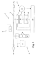
- FIG. 1 shows a system to be controlled in a block diagram 1 with a number of fields 2 and a display control 3, through a bus system 4 for data and information exchange are interconnected.
- Fig. 1 The fields 2, of which in Fig. 1 for reasons of clarity only one is explicitly shown First, work units characteristic of the nature of Appendix 1 5, such as handling systems in particular Form of industrial robots, but also machines, driven Devices such as welding guns, etc. on.
- system 1 a number of fieldbus modules 6, at least a fieldbus controller 6a and a data acquisition unit 7, which in turn with each other through a sub-bus system 8 (fieldbus) are connected.
- the field buses 8 are on the bus system 4 connected.
- the fieldbus controller 6a is preferably as a programmable logic controller (PLC) educated.
- PLC programmable logic controller
- the system controller 3 is composed of a real-time information server 9, a data stream controller 10 and a programmable controller 11, wherein the latter has input and output areas 12 and 13, respectively.
- the real-time information server 9 and the data stream controller 10 communicate with a real-time database 14.
- About the real time information server 9 is the connection of the system controller 3 to the bus system 4 ensured.
- the data stream controller 10 is the real time information server 9 downstream.
- the latter is with the input area 12 of the programmable logic controller 11 connected.
- the output area 13 of the programmable logic controller Controller 11 is back with the real time information server 9 connected so that the components 9 - 13 of the system controller 3 a (closed) control loop form.
- Appendix 1 Peripherals 15, e.g. Visualization devices or like that directly with the real-time information server 9 of the system controller 3 are connected. After the shown The peripheral devices are also an embodiment 15 able to access the real-time database 14.
- the actuator 5 e.g. an industrial robot used to control its peripherals (actuators, sensors; not shown in detail here) the fieldbus 8, i.e. a serial and digital transmission system in bus structure, but that is the large number of peripheral elements used (Fields 2) at certain time intervals by the Fieldbus control 6a can be queried.
- the fieldbus 8 i.e. a serial and digital transmission system in bus structure, but that is the large number of peripheral elements used (Fields 2) at certain time intervals by the Fieldbus control 6a can be queried.
- the fieldbus 8 i.e. a serial and digital transmission system in bus structure, but that is the large number of peripheral elements used (Fields 2) at certain time intervals by the Fieldbus control 6a can be queried.
- each field 2 of the system 1 schematically in Fig. 1 shown I / O modules (fieldbus modules) 6 through which the field data are communicated via the fieldbus 8.
- the Data acquisition unit 7 allows all to be read passively I / O data of the fieldbus modules
- the data acquisition unit 7 inputs the data of the field 2 in one adapted to the requirements of the system controller 3 Data stream format via the bus system 4 to the system controller 3 further.
- the bus system 4 is a local network (LAN) trained and preferably uses an Ethernet protocol for data transmission.
- the data transfer from the data acquisition devices 7 for system control 3 usually takes place asynchronously, i.e. she is not with them Control cycles of the actuating units 5 synchronized.
- the fieldbus modules 6 are commercially available digital or analog input and output modules connected to one central fieldbus master (PC plug-in card or embedded Hardware; not shown) are connected. On the part of the entire fieldbus 8 is program logic by the fieldbus PLC 6a controlled. Both the fieldbus PLC are preferred 6a and the PLC 11 of the system controller 3 as software-based programmable logic controllers (soft PLC) trained and executable on a PC.
- PC plug-in card or embedded Hardware not shown
- real-time information server 9 of the system control incoming fieldbus data either after appropriate preparation as historical process data (history data) in the form of RAD files (R ealtime A rchived D ata) archived in the real-time database 14, or directly to the stream controller 10 forwarded.
- the functioning of the real-time information server 9 is explained in more detail below with reference to FIG. 4.
- the data stream controller 10 is primarily intended to the PLC 11 with history data from the real-time database 14 to supply. Similar to the playback function the data stream controller 10 provides a video recorder the flow of process data to the input area 12 of the PLC 11 and allows precise positioning in this context within the data stream, fast forward or rewind, Slow motion, single data steps or the like, wherein the time stamps of the history data are used. The programmed logic of the PLC 11 then decides about the intention and the result of the data processing and puts the result in exit area 13 the PLC 11 again to the real-time information server 9 Available so that according to the system control 3 the possibility of a reference back to yourself and given the training to become a virtual machine (VM) is.
- VM virtual machine
- Peripheral devices 15 such as visualization or alarm devices, on the history data in the real-time database 14 access.
- process data can as shown in Fig. 1 - before archiving in the Real time database 14 through the real time information server 9 forwarded directly to certain peripheral devices 15 become.
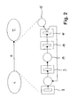
- FIG. 2 schematically illustrates the basic principle of the invention Control method that in a compression relatively simple information i in the form of real process data a system for complex information I, e.g. in shape compressed system characteristics.
- the procedure P is detailed in the lower part of FIG. 2 of a Petri net.
- Real process data with little information content i generated in the fieldbus 8 (see FIG. 1 and to the real-time information server 9 forwarded where usually the process data is processed (time coding, Data compression etc.). Then the process data stored as history data in the real-time database 14.
- the data stream controller 10 reads out history data the real-time database 14 and provides this depending on the selected Playback mode of the programmable controller 11 available.
- the output data of the PLC 11 are then fed back into the real-time information server 9 or stand as compressed characteristic data 16 with complex Information content I available for further processing.
- the data stored in the real-time database 14 and the characteristic data 16 can fundamentally correspond, depending on whether the PLC 11 as part of its control function the data is only interpreted or actively changed.
- Fig. 3 shows schematically the structure and data processing within the system controller 3 using a combined Block diagram flow diagram.
- the defined description of the entrance area (the input map) of the PLC 11 can both through a read-only operation as well as from a real-time database with active read / write operation (indicated by solid and dashed arrows in the left part of Fig. 3).
- the PLC 11 processes the received data for control purposes and in turn describes the exit area 13 (Output map). From the output area of the PLC 11, the Data passed back to the real-time information server 9, so that cascading by connecting an output area 13 with an entrance area 12.
- the PLC 12 as a pure software module, i.e. as a software-based PLC (Soft PLC) trained and executable on a PC 17.
- Soft PLC software-based PLC
- other components of the system control are also possible 3 to operate on a common PC 17, 17 ', what is indicated in Fig. 3 by the dash-dotted line is, so that for example the PLC software component and a real-time information server software component on and run the same PC.
- the control device is also in the Location, certain process data for direct further processing forward to the periphery 15.
- 3 shows a human-machine interface (Human Machine Interface HMI) 18 and an OPC server 19 (Object Linking and Embedding OLE for Process Control; Object Linking and embedding for process control).
- FIG. 3 again clearly shows as a control loop by cascading according to the invention is created within the system controller 3, by its back reference ensures that the invention Control device operable as a virtual machine (VM) and therefore in a particularly advantageous way for optimization or training purposes or the like is.
- VM virtual machine
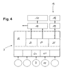
- Fig. 4 shows the detailed structure of the real-time information server 9. Since the real-time information server 9 preferably is designed as a software component, too the sub-components accordingly as software components or modules realized.
- the real-time information server 9 points different client programs on the input side, of which an RDS client 20 (Realtime Data Streamer; Real-time data streamer) and a reader for output data (from the output area 13 of the PLC 11) 21 explicitly are designated.
- RDS client 20 Realtime Data Streamer; Real-time data streamer
- reader for output data from the output area 13 of the PLC 11
- the real-time information server 9 includes a Translator program 22 (interpreter) and on the output side an archive file write program 23, an RDS server 24 and an OPC server 25.
- the real-time information server also contains 9 a data description file 26.
- Those recorded on the input side by the external servers 7, 11 Data are processed by the internal clients 20, 21, possibly translated by interpreter 22 and then the server 23, 24, 25 on the output side posed.
- the job of interpreter 22 is to bring recorded data into a format that is used for further processing by the corresponding client 23, 24, 25 suitable is.
- the archive file write program 23 is generated Data for archiving in the real-time database 14 (not shown here) are provided. This history data get, as shown in Fig. 1 to 3, through the database 14 and the data stream controller 10 to the PLC 11.
- the RDS server 24 a continuous stream of Real-time data that has not been archived by the PLC 11 be made available directly, whereby - as with here shown embodiment - the data stream controller 10 as an intermediate station between real-time information server 9 and PLC 11 can also serve for the real-time data stream.
- the OPC server 25 generates data in the form of OPC variables and provides this to one or more external OPC clients 19, such as the HMI 18 shown here, for example Analysis purposes.
- the real-time information server 9 also records With the help of specific programs the process data of different Data sources, archives certain parts of this data in a real-time database 14, preferably with a ring memory architecture (Shift register, FIFO buffer) and sets this data on request to different applications, among other things, the data stream controller 10 again available.
- a ring memory architecture Shift register, FIFO buffer
- the data description file 26 gives in this context which data with which programs and with which sampling recorded, archived in the real-time database 14 or looped directly for other applications; the latter either as a real-time data stream 24 to the data stream controller 10 or OPC variable 25 to the OPC client 19th
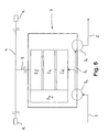
- Fig. 5 shows a block diagram of an embodiment of the Data acquisition unit 7 within the fieldbus 8 (compare Fig. 1)
- the data acquisition unit 7 is according to the invention for passive reading of all I / O data from modules 6 formed within the fieldbus 8 (fieldbus modules).
- it has a data input 7a and a data output 7b, which are internally optocouplers 7c are connected to one another, an interpreter 7d Shift register 7e and an RDS server 7f on the the unit 7 with the bus system 4 of the system 1 by means of Ethernet connection is connected.
- the Data acquisition unit 7 a data description file 7g, their entries for data handling by the software components 7d and 7f are decisive.
- Fieldbus data are generated by the data acquisition unit according to the invention 7 both processed and in the bus system 4 the system 1 fed in as well as directly from the data input 7a looped through to data output 7b so that they are within the field 2 of the actuating unit 5 or the fieldbus control 6a are available unchanged.
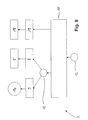
- Fig. 6 shows the procedure when using two according to the invention Control devices in the course of a Control simulation based on a Petri net display.
- the configuration of the controller 3 shown in FIG. 6 corresponds essentially the controls 3 as above have been described in detail with reference to FIGS. 1 and 3.
- the Output area 13 of the PLC / PLC-VM 11 not only with the Real-time information server 9, but also with that Input area 12 'connected to another PLC / PLC-VM 11'.
- the controller 3 'in the embodiment shown 6 with the program logic of their SPS / PLC-VM 11 'for generating simulated actuator / sensor process data trained them through their initial map 13 'the input area 12 of the PLC / PLC-VM 11 if necessary in connection with fed via a data stream controller 10 Provides history data. Since the invention Control devices 3, 3 'regularly for reading their own starting areas 13, 13 'in the course of the desired Cascading are designed for such Control simulations without further ado, i.e. without major programmable changes can be used. Furthermore can the regularly generated and archived in the database 14 History data offline, i.e. independent of time, can also be used and used for simulation purposes.
- FIG. 7 shows a flow diagram of a code optimization cycle. as he by the control method according to the invention or the control device according to the invention possible is.
- the cycle begins at VII.1, after which fieldbus data (sensor, actuator data etc.) is recorded at VII.2.
- a query VII.3 then takes place as to whether an optimization with simulation (j) or without simulation (n) is desired. If the answer to query VII.3 is affirmative, a reference file VII.4 is calculated, whereupon VII.5 - as in the case of a negative query VII.3 - a critical path analysis (Critical Path Analysis CPA) is carried out with the aim of critical Finding paths within the process to be optimized for which a given process duration T is greater than a predetermined maximum duration T max .
- CPA Critical Path Analysis
- the CPA method is a known method for scheduling and optimizing complex business, organizational or work processes, in which the most time-consuming path, which is decisive for the entire duration of a process, is determined as a sequence of individual process steps by setting up specific arrow diagrams , In this way, a CPA provides evidence of which procedural steps can be achieved through improved organization, such as improved control, a time advantage for the overall process.
- the reference file VII.4 or VII.11 mentioned above was parameterized the state of the to be simulated or optimized Plant and thus forms the link between Reality and simulation.
- the system controller 3 shown has a PLC / PLC-VM 11 with input and output areas 12 and 13 respectively.
- the data in the exit area 13 according to the invention a real-time information server 9 and a real-time database 14 provided.
- the Output data from output area 13 also via a field bus 8 for active control directly to an actuation unit 5 of the system, such as a robot, or on its actuators or sensors are routed.
- the SPS / PLC-VM 11 data also directly to an OPC server 25 which in the embodiment shown with an HMI 18 for visualization purposes communicates.
- the archiving of historical process data according to the invention (History data) in real time databases 14 is not limited to real process data. Archiving can in the course of the cascading mentioned Back reference also for condensed characteristic data 16, i.e. complex Information I according to FIG. 2 can be carried out.
- the archiving in RAD files for real process data as well as for compressed characteristic data 16 in the same way. This allows troubleshooting, process optimization or Employee training at practically any control level carry out.
- FIG. 9 illustrates the principle resulting information pyramid.
- the system 1 Control level A a number of fieldbus PLCs 6a - 6a "', and actuating devices 5, 5 ', for example industrial robots, the one another via a fieldbus system 8 and at plant level B with real-time information servers 9, 9 'are connected.
- the real-time information servers 9, 9 ' form a unit with SPS / PLC-VM 11, 11 'and others Real-time information servers 9a, 9a 'operating on line level C are arranged.
- the information servers 9a, 9a 'on line level C are over a bus system 4 with a further PLC-PLC-VM 11 '' and assigned Real-time information servers 9 '', 9a '' at area level D connected.
- area level D there is also a Human machine interface 18 (HMI) connected to bus 4.
- HMI Human machine interface 18
- a number of real-time information servers 9, 9a, 9a ', 9a ′′ are real-time databases in the manner according to the invention 14, 14a, 14a ', 14a' 'for archiving process data (Database 14) or more or less compressed characteristic data (Databases 14a, 14 ', 14a' '). It takes the degree of compression of the data with the number of data Processing steps from control level A to Plant level B and line level C towards area level D. to. This allows a number of cascading inventions according to the invention Control devices in increasing complexity Process peripheral data, process data, plant data, Generate line data and area data and archive.
Abstract
Description
Die Erfindung betrifft ein Verfahren zum Steuern einer Anlage, wie einer industriellen Produktionsanlage mit einer Anzahl von Arbeitseinheiten, wie Industrierobotern oder dergleichen, unter Verwendung wenigstens einer speicherprogrammierbaren Steuerung (SPS) sowie eine Vorrichtung zur Fehlersuche, Optimierung, Simulation und zum Informationsaustausch in elektronisch gesteuerten Anlagen, wie industriellen Produktionsanlagen mit einer Anzahl von Arbeiteinheiten.The invention relates to a method for controlling a system, like an industrial production plant with one Number of work units, such as industrial robots or the like, using at least one programmable logic controller Control (PLC) and a device for Troubleshooting, optimization, simulation and information exchange in electronically controlled systems, such as industrial ones Production facilities with a number of work units.
Speicherprogrammierbare elektronische Steuerungen (SPS), bei denen Steuerungsprogramme als Folge von Anweisungen in einem Programmspeicher festgelegt werden, finden in der Automatisierungstechnik als Anlagen- und Leitstandsteuerungen regelmäßig Verwendung. Dabei kann eine SPS ein nur für Steuerungszwecke vorgesehenes Steuerungsgerät aufweisen, das durch Einlesen eines bestimmten Steuerungsprogramms in den Programmspeicher an bestimmte Steuerungsaufgaben angepasst werden kann. Alternativ lassen sich SPS auch mit einem Universalrechner, wie einem üblichen Personalcomputer, realisieren, auf dem das entsprechende Steuerungsprogramm läuft (Soft-SPS), was aufgrund des Wegfalls spezieller Hardwarekomponenten zu einer Kostenersparnis führt. Darüber hinaus sind bei Verwendung einer Soft-SPS flexiblere Programmlogiken programmierbar, so dass der Einsatz von Soft-SPS in vielen Bereichen der Automatisierungstechnik heutzutage einen Standard darstellt, mit dem sich auf kostengünstige und effiziente Weise eine flexible Steuerung auch komplexer Anlagen durchführen lässt, wozu auch die Möglichkeit zur Vorsehung einer komfortablen Bedienungsoberfläche gegenüber einer herkömmlichen SPS beiträgt.Programmable logic controllers (PLC), where control programs as a result of instructions in a program memory can be found in automation technology as plant and control center controls regular use. A PLC can only be used for Have control device provided for control purposes, by reading a specific control program into the program memory adapted to certain control tasks can be. Alternatively, PLCs can also be used with a Universal computer, such as a common personal computer, realize on which the appropriate control program runs (soft PLC), which is more special due to the elimination Hardware components leads to cost savings. About that In addition, when using a soft PLC, more flexible program logic is available programmable so that the use of soft PLC in many areas of automation technology today represents a standard with which to focus on inexpensive and efficient way of flexible control too complex systems, including the possibility to provide a comfortable user interface compared to a conventional PLC.
Allerdings wirft der Einsatz flexibler speicherprogrammierbarer Steuerungen vor allem in komplexen und vielschichtigen Automatisierungsprozessen diverse technische Probleme auf, beispielsweise bei der Fehlersuche in der Anlage als auch im SPS-Programm selbst, bei der Optimierung von Fertigungsabläufen sowie im Rahmen nachträglicher, flexibler Fragestellungen (Kenndatengenerierung zu Prüf- oder Schulungszwecken), die bei bekannten SPS-gesteuerten Anlagen nicht bzw. nur unzureichend gelöst sind.However, the use of flexible programmable poses Controllers especially in complex and multi-layered Automation processes various technical problems on, for example when troubleshooting the system as also in the PLC program itself, when optimizing production processes as well as later, more flexible Questions (generation of characteristic data for testing or training purposes), the known PLC-controlled systems are not or only insufficiently solved.
Der Erfindung liegt ausgehend von den vorstehend beschriebenen Problemen und Nachteilen beim bekannten Stand der Technik die Aufgabe zugrunde, ein Verfahren und eine Vorrichtung zur elektronischen Anlagensteuerung dahingehend weiterzuentwickeln, dass diese in flexibler Weise auch zur Prozessanalyse, Anlagensimulation, Fehlersuche und Optimierung, zu Schulungszwecken und zur vorbeugenden Anlagen-Instandhaltung einsetzbar sind.The invention is based on those described above Problems and disadvantages with the known state of the art Technology based the task, a method and an apparatus for the electronic system control to further develop that in a flexible way to Process analysis, plant simulation, troubleshooting and optimization, for training purposes and for preventive plant maintenance can be used.
Diese Aufgabe wird bei einem Verfahren der eingangs genannten Art dadurch gelöst, dass historische Prozessdaten in die SPS eingespeist und durch eine Programmlogik der SPS verarbeitet werden. Unter historischen Prozessdaten oder kurz Historie-Daten werden gespeicherten Daten verstanden, sei es eines tatsächlichen früheren Prozessdurchlaufs oder künstlich kreierte, die die SPS so liest und verarbeitet, als kämen diese direkt von der Anlagenperipherie, z.B. einem die verschiedenen Aktoren und Sensoren einer Anlage verbindenden Feldbus.This task is carried out in a method of the type mentioned at the beginning Kind of solved in that historical process data in the PLC is fed and through a program logic of the PLC are processed. Under historical process data or briefly history data is understood stored data, be it an actual earlier process run or artificially created, which the PLC reads and processes in this way, as if they came directly from the system periphery, e.g. one the various actuators and sensors in a system connecting fieldbus.
Seitens einer Vorrichtung der eingangs genannten Art ist zur Lösung der Aufgabe vorgesehen, dass diese einen Echtzeit-Informationsserver zum Erfassen, Archivieren bzw. Weiterleiten jeweils bestimmter historischer Prozessdaten der Anlage und einen Datenstrom-Controller zum flexiblen Weitergeben archivierter Prozessdaten an wenigstens eine speicherprogrammierbare Steuerung (SPS) zum Steuern der Anlage aufweist, deren Ausgangsdaten wieder in die SPS einspeisbar sind.On the part of a device of the type mentioned To solve the task provided that this is a real-time information server for recording, archiving or forwarding certain historical process data of the System and a data stream controller for flexible distribution archived process data to at least one programmable logic controller Control (PLC) for controlling the system whose output data can be fed back into the PLC are.
Die Soft-SPS verarbeitet die Daten, auch die historischen, entsprechend ihrer Programmlogik und ist aufgrund des erfindungsgemäß realisierten Rückbezugs im Nachhinein in der Lage, bestimmte Prozessabläufe zu Analyse-, Optimierungsoder Schulungszwecken nachzuvollziehen.The soft PLC processes the data, including the historical, according to their program logic and is based on the invention realized back reference in the Able to process certain processes for analysis, optimization or Understand training purposes.
Nach einer Weiterentwicklung der Erfindung ist vorgesehen, dass die Prozessdaten vor der Einspeisung in die Soft-SPS in einer Echtzeit-Datenbank abgelegt und archiviert werden. Damit ist eine Verarbeitung von Prozessdaten sowohl im Online-Betrieb in Echtzeit als auch nachträglich im Offline-Betrieb möglich.According to a further development of the invention, that the process data before it is fed into the soft PLC stored and archived in a real-time database. This means that process data is processed both in online mode in real time and subsequently in offline mode possible.
Nach einer bevorzugten Ausgestaltung des erfindungsgemäßen Verfahrens ist vorgesehen, dass im Zuge des Ablegens eine Datenkompression und/oder eine Zeitcodierung stattfindet. According to a preferred embodiment of the invention The procedure provides for a Data compression and / or time coding takes place.
Nach einer bevorzugten Weiterentwicklung des erfindungsgemäßen Verfahrens ist vorgesehen, dass die Einspeisung zyklusgenau hinsichtlich eines Bearbeitungszyklus der SPS erfolgt. Zyklusgenaue Einspeisung bedeutet, dass die Einspeisung von Historie-Daten in die SPS in zeitlicher Abstimmung mit dem Verarbeitungstakt der SPS erfolgt. Vorzugsweise erfolgt dabei eine zyklische und/oder mit der Einspeisung synchrone Verarbeitung der Prozessdaten durch die SPS. In diesem Zusammenhang kann weiterhin vorgesehen sein, dass der Prozessdaten-Strom zur SPS mittels eines Datenstrom-Controllers hinsichtlich Datenumfang, Datenrate, zeitlichem Umfang oder dergleichen gesteuert wird. Dabei ist der Datenstrom-Controller in bevorzugter Ausgestaltung zum zeitlich genauen Auffinden, zur zeitlichen Vorwärts- und Rückwärtswiedergabe, zum beschleunigten und verlangsamten sowie zum mengenmäßig flexiblen Wiedergeben von historischen Prozessdaten ausgebildet. Die vorstehend genannten Ausgestaltungen des erfindungsgemäßen Verfahren bzw. der erfindungsgemäßen Vorrichtung ermöglichen ein flexibles nachträgliches Abarbeiten von Prozessabläufen, beispielsweise mit unterschiedlicher Geschwindigkeit oder Detailliertheit zur Fehlersuche oder zu Schulungszwecken. Dabei ist der zeitliche Prozessablauf durch den Datenstrom-Controller beliebig skalier- und steuerbar.According to a preferred further development of the invention The method provides that the feed is cycle-precise regarding a processing cycle of the PLC. Cycle-precise infeed means that the infeed of historical data in the PLC in time coordination with the processing clock of the PLC. Preferably done thereby a cyclical and / or with the infeed synchronous processing of the process data by the PLC. In In this context it can also be provided that the process data stream to the PLC using a data stream controller in terms of data volume, data rate, temporal Scope or the like is controlled. Here is the data stream controller in a preferred embodiment for the time exact location, for forward and backward playback, to accelerate and slow down as well for flexible, quantitative display of historical process data educated. The configurations mentioned above of the method according to the invention or of the invention Device allow a flexible subsequent Processing of process flows, for example with different ones Speed or level of detail Troubleshooting or for training purposes. Here is the temporal Any process flow through the data stream controller scalable and controllable.
In weiterer Ausgestaltung des erfindungsgemäßen Verfahrens ist vorgesehen, dass die Einspeisung der Prozessdaten online oder offline erfolgt. Da vorzugsweise Ergebnisse der Verarbeitung in einem Ausgangsbereich der SPS bereitgestellt werden, ergibt sich, dass die SPS durch kaskadierendes Verbinden ihres Eingangsbereichs mit ihrem Ausgangsbereich ggf. über weitere Datenstrom-Steuereinrichtungen quasi autark arbeiten kann, d.h. als virtuelle Maschine (VM) fungiert. Auf diese Weise ist die reale erfindungsgemäße SPS-Steuerung auch bei nichtinvasiver Anlagenbindung selbständig einsetzbar, was besonders im Optimierungs- und Schulungsbereich entscheidende (Kosten-)Vorteile mit sich bringt.In a further embodiment of the method according to the invention It is envisaged that the feed of the process data online or done offline. Because preferably results of Processing provided in an exit area of the PLC results in the PLC being cascaded Connect your entrance area to your exit area if necessary, via additional data flow control devices can work independently, i.e. as a virtual machine (VM) acts. In this way, the real one according to the invention PLC control even with non-invasive system binding applicable, which is particularly in the optimization and Training area with decisive (cost) advantages brings.
Nach einer Weiterentwicklung der Erfindung ist vorgesehen, dass die Prozessdaten an wenigstens einem Feldbus der Anlage generiert werden, wobei die historischen Prozessdaten nach der Reihenfolge ihrer Generierung in einem Schieberegister organisiert und jederzeit von einer Analyseeinheit lesbar und verarbeitbar sind. Dazu werden die historischen Prozessdaten vorzugsweise bei ihrer Generierung mit einer Zeitmarkierung versehen.According to a further development of the invention, that the process data on at least one fieldbus of the system are generated, with the historical process data according to the order of their generation in a shift register organized and at any time by an analysis unit are legible and processable. For this, the historical Process data preferably when it is generated with a Mark the time.
Die Analyseeinheit kann beispielsweise als Visualisierungseinheit zur optischen Prozessdatenanalyse ausgebildet sein, so dass jederzeit - online oder offline - eine Überwachung des Prozessablaufs möglich ist.The analysis unit can be used, for example, as a visualization unit be trained for optical process data analysis, so that monitoring at any time - online or offline of the process flow is possible.
Unter einem Feldbus versteht man einen zur Prozesssteuerung und Prozessüberwachung eingesetzt serielles und digitales Übertragungssystem, das als Busstruktur ausgelegt ist. Die große Anzahl der in automatisierten Fertigung eingesetzten Elemente (Sensoren, Aktoren), die auch als Feld bezeichnet werden und in bestimmten Zeitintervallen abgefragt werden müssen, erfordert eine komplex ausgelegte Kommunikationsstruktur zwischen den Elementen und der zentralen Steuerung. Diese Struktur ist als Bus realisiert. Durch die Generierung der historischen Prozessdaten direkt an wenigstens einem Feldbus der Anlage lässt sich eine flexible dezentralisierte Generierung von Prozessdaten erreichen, wodurch nicht zuletzt Systemkapazitäten der zentralen Steuerung (Soft-SPS) geschont werden. A fieldbus is a process control and process monitoring used serial and digital Transmission system that is designed as a bus structure. The large number of those used in automated manufacturing Elements (sensors, actuators), also referred to as a field and will be queried at certain time intervals requires a complex communication structure between the elements and the central control. This structure is implemented as a bus. By generation of the historical process data directly at least A fieldbus of the system can be flexibly decentralized Achieve process data generation, thereby not least system capacities of the central control (Soft PLC) are protected.
Nach einer Weiterbildung der Erfindung ist darüber hinaus vorgesehen, dass bestimmte vom Echtzeit-Informationsserver weitergeleitete Prozessdaten für andere Applikationen als Echtzeitdatenstrom oder in standardisierter Form als Objektverknüpfung und -einbettung (OLE) zur Prozesssteuerung bzw. -analyse verfügbar sind. Auf diese Weise ist zusätzlich zur erfindungsgemäßen Rückbezugs-Funktion auch das bloße Weiterleiten von Prozessdaten, beispielsweise zu Steuerungszwecken oder in Verbindung mit einem OPC-Client (OPC: OLE for Process Control) und einem Human-Machine-Interface (HMI) möglich.According to a development of the invention is beyond provided that certain from the real-time information server forwarded process data for applications other than Real-time data stream or in standardized form as an object link and embedding (OLE) for process control analysis are available. This way is additional for the back reference function according to the invention mere forwarding of process data, for example to Control purposes or in connection with an OPC client (OPC: OLE for Process Control) and a human-machine interface (HMI) possible.
Weiterhin weist die erfindungsgemäße Vorrichtung nach einer bevorzugten Ausgestaltung wenigstens eine Datenerfassungseinheit im Feldbussystem der Anlage auf. Die Datenerfassungseinheit ist vorzugsweise zum Zwischenspeichern der im Feldbus übertragenen Input/Output-Daten (I/O-Daten) ausgebildet und nach einer äußerst bevorzugten Ausgestaltung der Erfindung über ein lokales Netz (LAN) mit dem Echtzeit-Informationsserver verbunden.Furthermore, the device according to the invention has a preferred embodiment at least one data acquisition unit in the system's fieldbus system. The data acquisition unit is preferably for buffering the im Fieldbus transmitted input / output data (I / O data) and according to an extremely preferred embodiment of the Invention over a local area network (LAN) with the real-time information server connected.
Eine Datenerfassungseinheit erlaubt ein passives Mithören am Feldbussystem der Anlage. Sie "sieht" alle im Laufe eines Zyklus' des Feldbussystems übertragenen I/O-Daten der I/O-Module des Feldbusses (Feldbusmodule), speichert diese in einem Schieberegister zwischen und gibt die Information an einen Echtzeit-Informationsserver weiter. Eine derartige Architektur erlaubt die Kopplung mehrerer Datenerfassungseinheiten an ein und denselben Echtzeit-Informationsserver, woraus ein vereinfachter Netzaufbau resultiert. Die erfindungsgemäße LÁN-Verbindung zwischen Feldbus und der übergeordneten Steuerungssoftware, beispielsweise unter Verwendung des Ethernet-Protokolls, schafft einen standardisierten Übertragungsweg zwischen Steuerung und zu steuernder Anlage, was sich bei den Aufbau- und Wartungskosten sowie dem Wartungsaufwand günstig niederschlägt.A data acquisition unit allows passive eavesdropping on the system's fieldbus system. She "sees" everyone in the course of one Cycle 'of the fieldbus system transmitted I / O data I / O modules of the fieldbus (fieldbus modules), saves them in a shift register between and gives the information to a real-time information server. Such one Architecture allows the coupling of several data acquisition units to one and the same real-time information server, which results in a simplified network structure. The invention LÁN connection between fieldbus and the higher-level Control software, for example using of the ethernet protocol, creates a standardized Transmission path between the controller and the one to be controlled Plant, which in terms of construction and maintenance costs as well lowers maintenance costs.
Nach einer äußerst bevorzugten Weiterentwicklung des erfindungsgemäßen Verfahren ist vorgesehen, dass historische Prozessdaten und aktuelle Prozessdaten zur Einspeisung in die SPS kombiniert werden. Auf diese Weise lassen sich Weiterentwicklungen im Rahmen der Erfindung flexibel mit bestehenden Vorteilen bekannter Anlagensteuerungen kombinieren, um so prozessabhängig ein optimales Steuerungskonzept realisieren zu können.After an extremely preferred development of the invention The process is intended to be historical Process data and current process data for feeding into the PLC can be combined. In this way, further developments can be made flexible with existing within the scope of the invention Combine the advantages of known system controls, an optimal control concept depending on the process to be able to realize.
In bevorzugter Ausgestaltung kann vorgesehen sein, dass mindestens zwei speicherprogrammierbare Steuerungen durch kaskadierendes Verbinden ihrer Eingangsbereiche mit ihren Ausgangsbereichen ggf. über weitere Datenstrom-Steuereinrichtungen, eine virtuelle Maschine bildenIn a preferred embodiment it can be provided that at least two programmable logic controllers cascading connection of their entrance areas with their Output areas, if necessary, via further data flow control devices, form a virtual machine
Weiterhin ist vorgesehen, dass wenigstens die SPS und/oder der Echtzeit-Informationsserver als Softwarekomponenten eines PC ausgebildet sind. Auf diese Weise ist eine kompakte zentrale Steuerungsvorrichtung geschaffen, die zudem kostengünstig auf Standardtechnologien aufsetzt.It is further provided that at least the PLC and / or the real-time information server as software components of a PC are trained. This way it is compact central control device created, which is also inexpensive is based on standard technologies.
Weitere Einzelheiten und Vorteile der Erfindung ergeben sich aus der nachfolgenden Beschreibung von Ausführungsbeispielen anhand der Zeichnungen. Es zeigt:
- Fig. 1
- ein Blockschaltbild einer zu überwachenden Anlage und einer erfindungsgemäßen Steuerung;
- Fig. 2
- eine modellhafte Beschreibung des Grundprinzips des erfindungsgemäßen Steuerungsverfahrens;
- Fig. 3
- ein Blockschaltbild der erfindungsgemäßen Steuerungsvorrichtung;
- Fig. 4
- ein Blockschaltbild eines erfindungsgemäßen Echtzeit-Informationsservers;
- Fig. 5
- ein Blockschaltbild einer erfindungsgemäßen Datenerfassungseinheit;
- Fig. 6
- ein Ablaufdiagramm der Verwendung zweier erfindungsgemäßer Steuerungsvorrichtungen zu Simulationszwecken;
- Fig. 7
- ein Ablaufdiagramm des Einsatzes des erfindungsgemäßen Verfahrens bzw. der erfindungsgemäßen Steuerungsvorrichtung zu Optimierungszwecken;
- Fig. 8
- ein Blockschaltbild einer Mischform der erfindungsgemäßen Steuerungsvorrichtung; und
- Fig. 9
- ein Blockschaltbild einer erfindungsgemäß gesteuerten Anlage zur Verdeutlichung der Informationsverdichtung.
- Fig. 1
- a block diagram of a system to be monitored and a control according to the invention;
- Fig. 2
- a model description of the basic principle of the control method according to the invention;
- Fig. 3
- a block diagram of the control device according to the invention;
- Fig. 4
- a block diagram of a real-time information server according to the invention;
- Fig. 5
- a block diagram of a data acquisition unit according to the invention;
- Fig. 6
- a flowchart of the use of two control devices according to the invention for simulation purposes;
- Fig. 7
- a flowchart of the use of the method according to the invention and the control device according to the invention for optimization purposes;
- Fig. 8
- a block diagram of a mixed form of the control device according to the invention; and
- Fig. 9
- a block diagram of a system controlled according to the invention to illustrate the information compression.
Fig. 1 zeigt in einem Blockschaltbild eine zu steuernde Anlage
1 mit einer Anzahl von Feldern 2 und einer Ansigensteuerung
3, die durch ein Bussystem 4 zum Daten- und Informationsaustausch
miteinander verbunden sind.1 shows a system to be controlled in a block diagram
1 with a number of
Die Felder 2, von denen in Fig. 1 aus Gründen der Übersichtlichkeit
nur eines explizit dargestellt ist, weisen
zunächst für das Wesen der Anlage 1 charakteristische Arbeitseinheiten
5, wie insbesondere Handhabungssystemen in
Form von Industrierobotern, aber auch Maschinen, angetriebene
Geräte, wie Schweißzangen, u.a. auf. Daneben beinhaltet
die Anlage 1 eine Anzahl von Feldbusmodulen 6, wenigstens
eine Feldbus-Steuerung 6a sowie eine Datenerfassungseinheit
7, die ihrerseits untereinander durch ein Unterbussystem
8 (Feldbus) verbunden sind. Die Feldbusse 8 sind an
das Bussystem 4 angeschlossen. Die Feldbussteuerung 6a ist
vorzugsweise als speicherprogrammierbare Steuerung (SPS)
ausgebildet.The
Die Anlagensteuerung 3 setzt sich zusammen aus einem Echtzeit-Informationsserver
9, einem Datenstrom-Controller 10
sowie einer speicherprogrammierbaren Steuerung 11, wobei
letztere Eingangs- und Ausgangsbereiche 12 bzw. 13 aufweist.
Der Echtzeit-Informationsserver 9 und der Datenstrom-Controller
10 kommunizieren mit einer Echtzeit-Datenbank
14. Über den Echtzeit-Informationsserver 9 ist
die Verbindung der Anlagensteuerung 3 an das Bussystem 4
sichergestellt. Der Datenstrom-Controller 10 ist dem Echtzeit-Informationsserver
9 nachgeschaltet. Letzterer ist mit
dem Eingangsbereich 12 der speicherprogrammierbaren Steuerung
11 verbunden. Der Ausgangsbereich 13 der speicherprogrammierbaren
Steuerung 11 ist wieder mit dem Echtzeit-Informationsserver
9 verbunden, so dass die Komponenten 9 -
13 der Anlagensteuerung 3 einen (geschlossenen) Regelkreis
bilden.The
Über die genannten Komponenten hinaus weist die Anlage 1
Peripheriegeräte 15 auf, z.B. Visualisierungsgeräte oder
dergleichen, die direkt mit dem Echtzeit-Informationsserver
9 der Anlagensteuerung 3 in Verbindung stehen. Nach dem gezeigten
Ausführungsbeispiel sind auch die Peripheriegeräte
15 in der Lage, auf die Echtzeit-Datenbank 14 zuzugreifen.In addition to the components mentioned,
Die Betätigungseinheit 5, z.B. ein Industrieroboter, benutzt
zur Steuerung seiner Peripherie (Aktoren, Sensoren;
hier nicht im Detail gezeigt) den Feldbus 8, d.h. ein serielles
und digitales Übertragungssystem in Bus-Struktur,
aber das die große Anzahl der eingesetzten Peripherieelemente
(Felder 2) in bestimmten Zeitintervallen durch die
Feldbus-Steuerung 6a abgefragt werden. Zu diesem Zweck
weist jedes Feld 2 der Anlage 1 die in Fig. 1 schematisch
dargestellten I/O-Module (Feldbusmodule) 6 auf, durch die
die Felddaten über den Feldbus 8 kommuniziert werden. Die
Datenerfassungseinheit 7 erlaubt ein passives Mitlesen aller
I/O-Daten der Feldbusmodule 6 und ist in Fig. 5 näher
dargestellt.The
Die Datenerfassungseinheit 7 gibt die Daten des Feldes 2 in
einem an die Anforderungen der Anlagensteuerung 3 angepassten
Datenstromformat über das Bussystem 4 an die Anlagensteuerung
3 weiter. Das Bussystem 4 ist als lokales Netz
(LAN) ausgebildet und verwendet vorzugsweise ein Ethernet-Protokoll
zur Datenübertragung. Die Datenübertragung von
den Datenerfassungseinrichtungen 7 zur Anlagensteuerung 3
erfolgt in der Regel asynchron, d.h. sie ist nicht mit den
Steuerungszyklen der Betätigungseinheiten 5 synchronisiert.The
Bei den Feldbusmodulen 6 handelt es sich um handelsübliche
digitale oder analoge Ein- und Ausgangsmodule, die an einen
zentralen Feldbusmaster (PC-Einsteckkarte oder Embedded
Hardware; nicht gezeigt) angeschlossen sind. Auf Seiten der
Programmlogik wird der gesamte Feldbus 8 von der Feldbus-SPS
6a gesteuert. Vorzugsweise sind sowohl die Feldbus-SPS
6a als auch die SPS 11 der Anlagensteuerung 3 als softwarebasierte
speicherprogrammierbare Steuerungen (Soft-SPS)
ausgebildet und auf einem PC lauffähig.The
Am Echtzeit-Informationsserver 9 der Anlagensteuerung eintreffende
Feldbus-Daten werden entweder nach entsprechender
Aufbereitung als historische Prozessdaten (Historiedaten)
in Form von RAD-Dateien (Realtime Archived Data) in der
Echtzeit-Datenbank 14 archiviert oder direkt an den Datenstrom-Controller
10 weitergeleitet. Die Funktionsweise des
Echtzeit-Informationsservers 9 ist weiter unten anhand von
Fig. 4 näher erläutert.On real-time information server 9 of the system control incoming fieldbus data either after appropriate preparation as historical process data (history data) in the form of RAD files (R ealtime A rchived D ata) archived in the real-
Der Datenstrom-Controller 10 ist in erster Linie dazu vorgesehen,
die SPS 11 mit Historiedaten aus der Echtzeit-Datenbank
14 zu versorgen. Ähnlich der Widergabefunktion
eines Videorekorders liefert der Datenstrom-Controller 10
den Strom von Prozessdaten zum Eingangsbereich 12 der SPS
11 und erlaubt in diesem Zusammenhang ein genaues Positionieren
innerhalb des Datenstroms, schnellen Vor- oder Rücklauf,
Zeitlupen, Einzeldaten-Schritte oder dergleichen, wobei
die Zeitmarkierungen der Historiedaten Verwendung finden.
Die programmierte Logik der SPS 11 entscheidet anschließend
über die Intention und das Ergebnis der Datenverarbeitung
und stellt das Ergebnis im Ausgangsbereich 13
der SPS 11 erneut dem Echtzeit-Informationsserver 9 zur
Verfügung, so dass für die Anlagensteuerung 3 erfindungsgemäß
die Möglichkeit eines Rückbezugs auf sich selbst und
damit die Ausbildung zu einer virtuellen Maschine (VM) gegeben
ist.The
Neben dem Datenstrom-Controller 10 können auch ggf. weitere
Peripheriegeräte 15, wie Visualisierungs- oder Alarmierungsgeräte,
auf die Historiedaten in der Echtzeit-Datenbank
14 zugreifen. Bestimmte Prozessdaten können jedoch
wie in Fig. 1 dargestellt - vor einer Archivierung in der
Echtzeit-Datenbank 14 durch den Echtzeit-Informationsserver
9 direkt an bestimmte Peripheriegeräte 15 weitergeleitet
werden.In addition to the
Fig. 2 illustriert schematisch das Grundprinzip des erfindungsgemäßen Steuerungsverfahren, das in einer Verdichtung relativ einfacher Information i in Form von realen Prozessdaten einer Anlage zu komplexer Information I, z.B. in Form verdichteter Anlagen-Kenndaten, besteht. Der Verfahrensablauf P ist im unteren Teil der Fig. 2 detailliert anhand eines Petri-Netzes dargestellt.2 schematically illustrates the basic principle of the invention Control method that in a compression relatively simple information i in the form of real process data a system for complex information I, e.g. in shape compressed system characteristics. The procedure P is detailed in the lower part of FIG. 2 of a Petri net.
Reale Prozessdaten mit geringem Informationsgehalt i werden
im Feldbus 8 generiert (vergleiche Fig. 1 und an den Echtzeit-Informationsserver
9 weitergeleitet, wo in der Regel
eine Verarbeitung der Prozessdaten erfolgt (Zeitkodierung,
Datenkompression usw.). Anschließend werden die Prozessdaten
als Historiedaten in der Echtzeit-Datenbank 14 abgelegt.
Der Datenstrom-Controller 10 liest Historiedaten aus
der Echtzeit-Datenbank 14 und stellt diese je nach gewähltem
Wiedergabemodus der speicherprogrammierbaren Steuerung
11 zur Verfügung. Die Ausgangsdaten der SPS 11 werden anschließend
wieder in den Echtzeit-Informationsserver 9 eingespeist
oder stehen als verdichtete Kenndaten 16 mit komplexem
Informationsgehalt I zur Weiterverarbeitung zur Verfügung.
Die in der Echtzeit-Datenbank 14 gespeicherten Daten
und die Kenndaten 16 können sich grundsätzlich entsprechen,
je nachdem, ob die SPS 11 im Rahmen ihrer Steuerungsfunktion
die Daten lediglich interpretiert oder aktiv verändert.Real process data with little information content i
generated in the fieldbus 8 (see FIG. 1 and to the real-time information server
9 forwarded where usually
the process data is processed (time coding,
Data compression etc.). Then the process data
stored as history data in the real-
Im Rahmen einer stufenweise Informationsverdichtung ist es
auch möglich, bereits verdichtete Kenndaten 16 in einer Datenbank
14 abzulegen. Die sich daraus ergebende Informationspyramide
wird weiter unten mit Blick auf Fig. 9 erläutert.It is within the framework of a gradual information compression
also possible, already compressed
Fig. 3 zeigt schematisch den Aufbau und die Datenverarbeitung
innerhalb der Anlagensteuerung 3 anhand eines kombinierten
Blockschaltbild-Ablaufdiagramms. Fig. 3 shows schematically the structure and data processing
within the
Reale Prozessdaten aus den Feldbussen 8 der Anlage 1 gelangen
als einfache Information i (vgl. Fig. 2) zum Echtzeit-Informationsserver
9 der Anlagensteuerung 3. Von dort aus
werden die Daten direkt zur Peripherie 15 weitergeschleift
oder in der Echtzeit-Datenbank 14 archiviert. Von dort
liest sie der Datenstrom-Controller 10, der die nun als Historiedaten
vorliegenden Prozessdaten in Abstimmung mit dem
Steuerungszyklus der SPS 11 an deren Eingangsbereich 12
weiterleitet. Das dadurch definierte Beschreiben des Eingangsbereichs
(der Eingangs-Map) der SPS 11 kann sowohl
durch einen reinen Lese-Betrieb als auch von einer Echtzeitdatenbank
mit aktivem Schreib-/Lesebetrieb erfolgen
(angedeutet durch durchgezogene und gestrichelte Pfeile im
linken Teil der Fig. 3).Real process data from the
Die SPS 11 verarbeitet die empfangenen Daten zu Steuerungszwecken
und beschreibt ihrerseits den Ausgangsbereich 13
(Ausgangs-Map). Vom Ausgangsbereich der SPS 11 werden die
Daten zurück zum Echtzeit-Informationsserver 9 geleitet, so
dass eine Kaskadierung durch Verbinden eines Ausgangsbereichs
13 mit einem Eingangsbereich 12 erfolgt.The
Beim gezeigten Ausführungsbeispiel der Fig. 3 ist die SPS
12 als reines Software-Modul, d.h. als softwarebasierte SPS
(Soft-SPS) ausgebildet und auf einem PC 17 lauffähig. Es
ist jedoch auch möglich, weitere Komponenten der Anlagensteuerung
3 auf einem gemeinsamen PC 17, 17' zu betreiben,
was in Fig. 3 durch die strichpunktierte Linie angedeutet
ist, so dass beispielsweise die SPS-Softwarekomponente und
eine Echtzeit-Informationsserver-Softwarekomponente auf ein
und demselben PC laufen.In the exemplary embodiment shown in FIG. 3, the
Die erfindungsgemäße Steuerungsvorrichtung ist auch in der
Lage, bestimmte Prozessdaten zur direkten Weiterverarbeitung
an die Peripherie 15 weiterzuleiten. Beispielhafterweise
zeigt Fig. 3 eine Mensch-Maschine-Schnittstelle
(Human Machine Interface HMI) 18 sowie einen OPC-Server 19
(Object Linking and Embedding OLE for Process Control; Objektverknüpfung
und -einbettung zur Prozesssteuerung).The control device according to the invention is also in the
Location, certain process data for direct further processing
forward to the
Die Darstellung der Fig. 3 zeigt noch einmal anschaulich,
wie durch das erfindungsgemäße Kaskadieren ein Regelkreis
innerhalb der Anlagensteuerung 3 geschaffen ist, der durch
seinen Rückbezug dafür sorgt, dass die erfindungsgemäße
Steuerungsvorrichtung als virtuelle Maschine (VM) betreibbar
und deshalb in besonders vorteilhafter Weise zu Optimierungs-
oder Schulungszwecken oder dergleichen einsetzbar
ist.The illustration in FIG. 3 again clearly shows
as a control loop by cascading according to the invention
is created within the
Fig. 4 zeigt den detaillierten Aufbau des Echtzeit-Informationsservers 9. Da der Echtzeit-Informationsserver 9 vorzugsweise als Softwarekomponente ausgebildet ist, sind auch die Unterkomponenten entsprechend als Software-Komponenten bzw. -module realisiert.Fig. 4 shows the detailed structure of the real-time information server 9. Since the real-time information server 9 preferably is designed as a software component, too the sub-components accordingly as software components or modules realized.
Der erfindungsgemäße Echtzeit-Informationsserver 9 weist
eingangsseitig verschiedene Client-Programme auf, von denen
exemplarisch ein RDS-Client 20 (Realtime Data Streamer;
Echtzeit-Datenstreamer) und ein Leseprogramm für Ausgangsdaten
(aus dem Ausgangsbereich 13 der SPS 11) 21 explizit
bezeichnet sind.The real-time information server 9 according to the invention points
different client programs on the input side, of which
an RDS client 20 (Realtime Data Streamer;
Real-time data streamer) and a reader for output data
(from the
Weiterhin umfasst der Echtzeit-Informationsserver 9 ein
Übersetzer-Programm 22 (Interpreter) sowie ausgangsseitig
ein Archivdatei-Schreibprogramm 23, einen RDS-Server 24 und
einen OPC-Server 25. Zudem enthält der Echtzeit-Informationsserver
9 eine Daten-Beschreibungsdatei 26.Furthermore, the real-time information server 9 includes a
Translator program 22 (interpreter) and on the output side
an archive
Die eingangsseitig von den externen Servern 7, 11 aufgenommenen
Daten werden durch die internen Clients 20, 21 verarbeitet,
ggf. durch den Interpreter 22 übersetzt und anschließend
den ausgangsseitigen Server 23, 24, 25 zur Verfügung
gestellt. Aufgabe des Interpreters 22 ist es, die
aufgenommenen Daten in ein Format zu bringen, das zur Weiteverarbeitung
durch den entsprechenden Client 23, 24, 25
geeignet ist. Das Archivdatei-Schreibprogramm 23 erzeugt
Daten, die zur Archivierung in der Echtzeit-Datenbank 14
(hier nicht gezeigt) vorgesehen sind. Diese Historiedaten
gelangen, wie in Fig. 1 bis 3 gezeigt, über die Datenbank
14 und den Datenstrom-Controller 10 zur SPS 11. Dagegen erzeugt
der RDS-Server 24 einen kontinuierlichen Strom von
Echtzeitdaten, die ohne vorherige Archivierung der SPS 11
direkt zur Verfügung gestellt werden, wobei - wie beim hier
gezeigten Ausführungsbeispiel - der Datenstrom-Controller
10 als Zwischenstation zwischen Echtzeit-Informationsserver
9 und SPS 11 auch für den Echtzeit-Datenstrom dienen kann.
Der OPC-Server 25 erzeugt Daten in Form von OPC-Variablen
und stellt diese einem oder mehreren externen OPC-Clients
19, wie dem hier dargestellten HMI 18, beispielsweise zu
Analysezwecken, zur Verfügung.Those recorded on the input side by the
Generell erfasst also der Echtzeit-Informationsserver 9 mit
Hilfe spezifischer Programme die Prozessdaten von verschiedenen
Datenquellen, archiviert bestimmte Teile dieser Daten
in einer Echtzeit-Datenbank 14, vorzugsweise mit Ringspeicherarchitektur
(Schieberegister, FIFO-Buffer) und stellt
diese Daten auf Anforderung verschiedenen Applikationen,
unter anderem dem Datenstrom-Controller 10, wieder zur Verfügung.In general, the real-time information server 9 also records
With the help of specific programs the process data of different
Data sources, archives certain parts of this data
in a real-
Die Daten-Beschreibungsdatei 26 gibt in diesem Zusammenhang
an, welche Daten mit welchen Programmen und mit welcher Abtastung
erfasst, in der Echtzeit-Datenbank 14 archiviert
bzw. direkt für andere Applikationen weitergeschleift werden;
letzteres entweder als Echtzeit-Datenstrom 24 zum Datenstrom-Controller
10 oder OPC-Variable 25 zum OPC-Client
19.The
Fig. 5 zeigt ein Blockschaltbild einer Ausführungsform der
Datenerfassungseinheit 7 innerhalb des Feldbusses 8 (vergleiche
Fig. 1) Die Datenerfassungseinheit 7 ist erfindungsgemäß
zum passiven Mitlesen aller I/O-Daten von Modulen
6 innerhalb des Feldbusses 8 (Feldbusmodule) ausgebildet.
Sie weist zu diesem Zweck neben einem Dateneingang 7a
und einem Datenausgang 7b, die durch Optokoppler 7c intern
miteinander verbunden sind, noch einen Interpreter 7d, ein
Schieberegister 7e sowie einen RDS-Server 7f auf, über den
die Einheit 7 mit dem Bussystem 4 der Anlage 1 mittels
Ethernet-Verbindung verbunden ist. Weiterhin umfasst die
Datenerfassungseinheit 7 eine Daten-Beschreibungsdatei 7g,
deren Einträge für die Datenbehandlung durch die Software-Komponenten
7d und 7f maßgeblich sind.Fig. 5 shows a block diagram of an embodiment of the
Feldbus-Daten werden durch die erfindungsgemäße Datenerfassungseinheit
7 sowohl verarbeitet und in das Bussystem 4
der Anlage 1 eingespeist als auch direkt vom Dateneingang
7a zum Datenausgang 7b durchgeschleift, so dass sie innerhalb
des Feldes 2 der Betätigungseinheit 5 bzw. der Feldbus-Steuerung
6a unverändert zur Verfügung stehen.Fieldbus data are generated by the data acquisition unit according to the
Fig. 6 zeigt den Verfahrensablauf bei Verwendung zweier erfindungsgemäßer Steuerungsvorrichtungen im Zuge einer Steuerungssimulation anhand einer Petri-Netz-Darstellung.Fig. 6 shows the procedure when using two according to the invention Control devices in the course of a Control simulation based on a Petri net display.
Zu Zwecken der Steuerungssimulation sind beim gezeigten
Ausführungsbeispiel zwei erfindungsgemäße Anlagensteuerungen
3, 3', wie vorstehend beschrieben, hintereinandergeschaltet,
wobei aus Gründen einer vereinfachenden Darstellung
von der Steuerung 3' nur die SPS 11' mit ihren Eingangs-
und Ausgangsbereichen 12' bzw. 13' gezeigt ist. Da
bei Verwendung des erfindungsgemäßen Verfahrens das Steuerungsprogramm
der SPS 11, 11' auch ohne direkte Anlagenbindung
ablaufen kann, lassen sich die SPS 11, 11' auch als
virtuelle Maschinen mit programmierbarer Logiksteuerung
(Programmable Logic Control-Virtual Machine PLC-VM) bezeichnen.For the purposes of control simulation are shown in the
Embodiment two system controls according to the
Die in Fig. 6 gezeigte Ausgestaltung der Steuerung 3 entspricht
im wesentlichen den Steuerungen 3, wie sie vorstehend
anhand von Fig. 1 und 3 ausführlich beschrieben wurden.
Allerdings ist im Zuge der Steuerungssimulation der
Ausgangsbereich 13 der SPS/PLC-VM 11 nicht nur mit dem
Echtzeit-Informationsserver 9, sondern zusätzlich mit dem
Eingangsbereich 12' einer weiteren SPS/PLC-VM 11' verbunden.
Deren Ausgangsbereich 13' wiederum steht in Verbindung
mit dem Eingangsbereich 12 der ersten SPS/PLC-VM 11.The configuration of the
Um das Verhalten einer erfindungsgemäßen Anlagensteuerung
beispielsweise zu Ausbildungszwecken ohne Anlagenbindung zu
simulieren, ist die Steuerung 3' beim gezeigten Ausführungsbeispiel
der Fig. 6 mit der Programmlogik ihrer
SPS/PLC-VM 11' zum Generieren simulierter Aktor-/Sensor-Prozessdaten
ausgebildet, die sie über ihre Ausgangs-Map
13' dem Eingangsbereich 12 der SPS/PLC-VM 11 ggf. in Verbindung
mit über einen Datenstrom-Controller 10 eingespeisten
Historiedaten zur Verfügung stellt. Da die erfindungsgemäßen
Steuerungsvorrichtungen 3, 3' regelmäßig zum Lesen
ihrer eigenen Ausgangsbereiche 13, 13' im Zuge der angestrebten
Kaskadierung ausgebildet sind, sind sie für derartige
Steuerungssimulationen ohne weiteres, d.h. ohne größere
programmtechnische Änderungen einsetzbar. Darüber hinaus
können die regelmäßig erzeugten und in der Datenbank 14 archivierten
Historiedaten offline, also zeitlich unabhängig,
auch zu Simulationszwecke herangezogen und verwendet werden. To the behavior of a system control according to the invention
for example for training purposes without tying up equipment
simulate, the controller 3 'in the embodiment shown
6 with the program logic of their
SPS / PLC-VM 11 'for generating simulated actuator / sensor process data
trained them through their initial map
13 'the
Aufgrund der erwähnten Offline-Fähigkeit und der anhand von Fig. 6 erläuterten Steuerungssimulation eignet sich das erfindungsgemäße Verfahren bzw. die erfindungsgemäße Steuerungsvorrichtung in besonderer Weise zum Optimieren von SPS-Code.Due to the offline ability mentioned and the based on 6, the control simulation explained is suitable for the invention Method and the control device according to the invention in a special way to optimize PLC code.
Fig. 7 zeigt ein Ablaufdiagramm eines Code-Optimierungszyklus' wie er durch das erfindungsgemäße Steuerungsverfahren bzw. die erfindungsgemäße Steuerungsvorrichtung möglich ist.7 shows a flow diagram of a code optimization cycle. as he by the control method according to the invention or the control device according to the invention possible is.
Der Zyklus beginnt bei VII.1, worauf bei VII.2 ein Aufzeichnen von Feldbusdaten (Sensor-, Aktordaten etc.) erfolgt. Anschließend erfolgt eine Abfrage VII.3, ob eine Optimierung mit Simulation (j) oder ohne Simulation (n) gewünscht ist. Ein Bejahen der Abfrage VII.3 führt zu einer Berechnung einer Referenzdatei VII.4, woraufhin bei VII.5 - wie auch für den Fall einer verneinten Abfrage VII.3 eine kritische Pfadanalyse (Critical Path Analysis CPA) durchgeführt wird mit dem Ziel, kritische Pfade innerhalb des zu optimierenden Prozesses zu finden, für die eine gegebene Prozessdauer Tist größer als eine vorgegebene Maximaldauer Tmax ist. Die CPA-Methode ist ein an sich bekanntes Verfahren zur zeitlichen Planung und Optimierung von komplexen Geschäfts-, Organisations- oder Arbeitsvorgängen, bei der durch Aufstellen bestimmter Pfeildiagramme der zeitintensivste und damit für die Gesamtdauer eines Prozesses maßgebliche Pfad als eine Abfolge von einzelnen Prozessschritten ermittelt wird. Auf diese Weise liefert eine CPA Indizien dafür, hinsichtlich welcher Verfahrensschritte sich durch verbesserte Organisation, z.B. verbesserte Steuerung, ein Zeitvorteil für den Gesamtprozess erzielen lässt. The cycle begins at VII.1, after which fieldbus data (sensor, actuator data etc.) is recorded at VII.2. A query VII.3 then takes place as to whether an optimization with simulation (j) or without simulation (n) is desired. If the answer to query VII.3 is affirmative, a reference file VII.4 is calculated, whereupon VII.5 - as in the case of a negative query VII.3 - a critical path analysis (Critical Path Analysis CPA) is carried out with the aim of critical Finding paths within the process to be optimized for which a given process duration T is greater than a predetermined maximum duration T max . The CPA method is a known method for scheduling and optimizing complex business, organizational or work processes, in which the most time-consuming path, which is decisive for the entire duration of a process, is determined as a sequence of individual process steps by setting up specific arrow diagrams , In this way, a CPA provides evidence of which procedural steps can be achieved through improved organization, such as improved control, a time advantage for the overall process.
Im Anschluss an die CPA VII.5 erfolgt bei VII.6 eine Abfrage, ob nach der CPA ein Optimierungspotential vorhanden ist (Tist > Tmax) oder nicht. Ein Verneinen dieser Abfrage beendet bei VII.7 den Optimierungszyklus.Following CPA VII.5, VII.6 asks whether there is optimization potential after the CPA (T is > T max ) or not. A negative answer to this query ends the optimization cycle in VII.7.
Wird dagegen die Abfrage VII.6 bejaht, so ergeht bei VII.8 eine erneute Anfrage, ob eine Optimierung mit oder ohne Simulation durchgeführt werden soll. Ein Verneinen dieser Anfrage führt direkt zu einer Änderung der Programmlogik in der Anlage VII.9, woraufhin der Optimierungszyklus ausgehend von VII.1 erneut durchlaufen werden kann.If, however, query VII.6 is answered in the affirmative, VII.8 a renewed request for optimization with or without simulation to be carried out. A negative of this request leads directly to a change in the program logic in Annex VII.9, whereupon the optimization cycle starts can be run through again from VII.1.
Wird dagegen bei VII.8 eine Optimierung mit Simulation gewünscht, so erfolgt eine Programmänderung nach Maßgabe der CPA nicht in der Anlage selbst sondern nur in deren Simulation (vergleiche Fig. 6). Anschließend wird bei VII.11 eine neue Referenzdatei für die Anlage berechnet. Der Zyklus wird dann bei VII.5 mit einer erneuten CPA fortgesetzt.However, if optimization with simulation is desired in VII.8, a program change takes place in accordance with the CPA not in the plant itself, but only in its simulation (see Fig. 6). Then at VII.11 new reference file for the system is calculated. The cycle then continues at VII.5 with another CPA.
Die vorstehend erwähnte Referenzdatei VII.4 bzw. VII.11 parametrisiert den Zustand der zu simulierenden bzw. zu optimierenden Anlage und stellt somit das Bindeglied zwischen Realität und Simulation dar. Vorzugsweise ist eine real existierende Anlage durch ihre Referenzdatei bezüglich der Simulation eindeutig definiert; ebenso lässt sich aus einer simulierten Referenzdatei eindeutig auf die reale Anlage bzw. die sie steuernde Programmlogik schließen.The reference file VII.4 or VII.11 mentioned above was parameterized the state of the to be simulated or optimized Plant and thus forms the link between Reality and simulation. Preferably one is real existing plant through its reference file regarding the Simulation clearly defined; likewise one can simulated reference file clearly on the real plant or close the program logic controlling them.
Die Erfindung ist nicht auf die bislang beispielhaft erläuterten Verfahrensabläufe bzw. Steuerungsvorrichtungen beschränkt. Insbesondere lassen sich im Rahmen der Erfindung auch verschiedenartige Mischformen des erfindungsgemäßen Steuerungsverfahrens mit anderen an sich bekannten SPS-Steuerungsverfahren realisieren. The invention is not based on the examples previously explained Processes and control devices limited. In particular, within the scope of the invention also various types of mixed forms of the invention Control method with other known PLC control methods realize.
Fig. 8 zeigt schematisch eine solche Mischform.8 schematically shows such a mixed form.
Die gezeigte Anlagensteuerung 3 weist eine SPS/PLC-VM 11
mit Eingangs- und Ausgangsbereichen 12 bzw. 13 auf. Die Daten
im Ausgangsbereich 13 werden erfindungsgemäß wiederum
einem Echtzeit-Informationsserver 9 und einer Echtzeit-Datenbank
14 zur Verfügung gestellt. Zusätzlich können die
Ausgangsdaten vom Ausgangsbereich 13 auch über einen Feldbus
8 zur aktiven Steuerung direkt an eine Betätigungseinheit
5 der Anlage, wie einen Roboter, bzw. an deren Aktoren
oder Sensoren geleitet werden. Parallel übermittelt die
SPS/PLC-VM 11 Daten auch direkt an einen OPC-Server 25, der
beim gezeigten Ausführungsbeispiel mit einer HMI 18 zu Visualisierungszwecken
in Verbindung steht.The
Auf diese Weise lassen sich die bekannten Möglichkeiten der Anlagensteuerung mittels SPS mit den Vorteilen der Erfindung kombinieren.In this way, the known possibilities of System control using PLC with the advantages of the invention combine.
Das erfindungsgemäße Archivieren von historischen Prozessdaten
(Historiedaten) in Echtzeit-Datenbanken 14 ist nicht
auf reale Prozessdaten beschränkt. Vielmehr kann eine Archivierung
im Verlauf der angesprochenen Kaskadierung durch
Rückbezug auch für verdichtete Kenndaten 16, d.h. komplexe
Informationen I gemäß Fig. 2 durchgeführt werden. Die Archivierung
in RAD-Dateien erfolgt für reale Prozessdaten
wie auch für verdichtete Kenndaten 16 in gleicher Weise.
Somit lässt sich eine Fehlersuche, Prozessoptimierung oder
Mitarbeiterschulung auf praktisch jeder beliebigen Steuerungsebene
durchführen.The archiving of historical process data according to the invention
(History data) in
Die Darstellung in Fig. 9 verdeutlicht die aus diesem Prinzip resultierende Informationspyramide. The illustration in FIG. 9 illustrates the principle resulting information pyramid.
Beim gezeigten Ausführungsbeispiel weist die Anlage 1 auf
Steuerungsebene A eine Anzahl von Feldbus-SPS 6a - 6a"',
und Betätigungseinrichtungen 5, 5' auf, beispielsweise Industrieroboter,
die über ein Feldbussystem 8 untereinander
und auf Anlagenebene B mit Echtzeit-Informationsservern 9,
9' verbunden sind. Die Echtzeit-Informationsserver 9, 9'
bilden eine Einheit mit SPS/PLC-VM 11, 11' und weiteren
Echtzeit-Informationsservern 9a, 9a', die auf Linienebene C
angeordnet sind.In the embodiment shown, the
Die Informationsserver 9a, 9a' auf Linienebene C sind über
ein Bussystem 4 mit einer weiteren SPS-PLC-VM 11'' und zugeordneten
Echtzeitinformationsservern 9'' , 9a'' auf Bereichebene
D verbunden. Auf Bereichsebene D ist auch eine
Mensch-Maschine-Schnittstelle 18 (HMI) an den Bus 4 angeschlossen.The information servers 9a, 9a 'on line level C are over
a
Einer Anzahl von Echtzeit-Informationsservern 9, 9a, 9a',
9a'' sind in erfindungsgemäßer Weise Echtzeit-Datenbanken
14, 14a, 14a', 14a'' zum Archivieren von Prozessdaten
(Datenbank 14) bzw. mehr oder weniger verdichteter Kenndaten
(Datenbanken 14a, 14', 14a'') zugeordnet. Dabei nimmt
der Verdichtungsgrad der Daten mit der Anzahl der erfolgten
Verarbeitungsschritte von der Steuerungsebene A über die
Anlageebene B und die Linienebene C zur Bereichsebene D hin
zu. Damit lassen sich durch eine Anzahl kaskadierender erfindungsgemäßer
Steuerungsvorrichtungen in steigender Komplexität
Prozessperipheriedaten, Prozesskenndaten, Anlagenkenndaten,
Linienkenndaten und Bereichskenndaten erzeugen
und archivieren.A number of real-time information servers 9, 9a, 9a ',
9a ″ are real-time databases in the manner according to the
Auf diese Weise lässt sich jedes gewünschte Maß an Transparenz durch Historiedaten mit angepasster Auflösung verwirklichen. Für alle mit Anlagensteuerung befassten Abteilungen und Bereiche eines Unternehmens, sei es bei der Einrichtung, der Instandhaltung oder der Mitarbeiterschulung, herrscht dabei ein einheitlicher Sprachgebrauch, und es finden gleiche Werkzeuge, Datenformate usw. Anwendung, so dass eine durchgängige Verbindung von Büro- und Steuerungswelt möglich ist. Dies führt zu einer erheblichen Kostenreduktion durch Homogenisierung und führt für die vorstehend beschriebene Erfindung zu einem hohen Return of Investment. In this way, any desired level of transparency can be achieved through historical data with adapted resolution. For all departments concerned with system control and areas of a company, be it in the establishment, maintenance or employee training, there is a uniform use of language, and it find the same tools, data formats, etc., so that a continuous connection between office and control world is possible. This leads to a considerable reduction in costs through homogenization and leads for the above described invention for a high return of investment.
- 11
- Anlageinvestment
- 22
- Feldfield
- 33
- Anlagesteuerungsystem control
- 44
- Bus/BussystemBus / bus system
- 55
- Betätigungseinheit/RoboterActuator / robot
- 66
- Feldbusmodule/IO-ModuleFieldbus / IO modules
- 6a, 6a', 6a"6a, 6a ', 6a "
- speicherprogrammierbare Steuerung für Feldbus (Feldbus-SPS)programmable logic controller for Fieldbus (fieldbus PLC)
- 77
- DatenerfassungseinheitData acquisition unit
- 7a7a
- Dateneingangdata input
- 7b7b
- Datenausgangdata output
- 7c7c
- Optokoppleroptocoupler
- 7d7d
- Interpreterinterpreter
- 7e7e
- Schieberegistershift register
- 7f7f
- RDS-ServerRDS server
- 7g7g
- Daten-BeschreibungsdateiData description file
- 88th
- Feldbusfieldbus
- 9, 9a, 9a', 9a''9, 9a, 9a ', 9a' '
-
Echtzeit-Informationsserver
(Realtime Information Server RIS) Real-time Information Server
(Realtime Information Server RIS) - 1010
- Datenstrom-Controller (DSC)Data flow controller (DSC)
- 11, 11', 11''11, 11 ', 11' '
- (softwarebasierte) speicherprogrammierbare Steuerung SPS(software-based) programmable logic PLC control
- 12, 12'12, 12 '
- Eingangsbereich (von 11, 11')Entrance area (from 11, 11 ')
- 13, 13'13, 13 '
- Ausgangsbereich (von 11, 11')Output area (from 11, 11 ')
- 14,14a,14a',14a''14,14a, 14a ', 14a' '
- Echtzeit-DatenbankReal-time database
- 1515
- Peripherie(-Geräte)Peripherals (devices)
- 1616
- KenndatenSpecifications
- 17, 17'17, 17 '
- PCPC
- 1818
- Human Machine Interface HMIHuman machine interface HMI
- 1919
- OPC-ClientOPC client
- 2020
- Realtime Data Streamer RDSRealtime Data Streamer RDS
- 2121
- Leseprogramm für AusgangsdatenRead program for output data
- 2222
- Interpreterinterpreter
- 2323
- Archivdatei-SchreibprogrammArchive file write program
- 2424
- RDS-ServerRDS server
- 2525
- OPC-ServerOPC server
- 2626
- Daten-BeschreibungsdateiData description file
- AA
- Steuerungsebenecontrol level
- BB
- Anlagenebeneplant level
- CC
- Linienebeneline level
- DD
- Bereichsebenearea level
- RR
- Abschlusswiderstandterminator
- PP
- Steuerungsverfahrencontrol method
- VII.1 - VII.11VII.1 - VII.11
- Optimierungsschritteoptimization steps
Claims (30)
einem Echtzeit-Informationsserver (9) zum Erfassen, Archivieren bzw. Weiterleiten jeweils bestimmter historischer Prozessdaten der Anlage (1) und
einem Daten-Controller (10) zum flexiblen Wiedergeben archivierter Prozessdaten an
wenigstens eine speicherprogrammierbare Steuerung (11) SPS zum Steuern der Anlage (1),
deren Ausgangsdaten wieder in die SPS (11) oder eine andere SPS einspeisbar sind.Device for troubleshooting, optimization, simulation and information exchange in electronically controlled systems (1), such as industrial production systems with a number of work units, such as industrial robots (5) or the like
a real-time information server (9) for recording, archiving or forwarding specific historical process data of the system (1) and
a data controller (10) for flexible playback of archived process data
at least one programmable logic controller (11) PLC for controlling the system (1),
whose output data can be fed back into the PLC (11) or another PLC.
Applications Claiming Priority (2)
| Application Number | Priority Date | Filing Date | Title |
|---|---|---|---|
| DE10233553 | 2002-07-24 | ||
| DE10233553 | 2002-07-24 |
Publications (2)
| Publication Number | Publication Date |
|---|---|
| EP1385070A2 true EP1385070A2 (en) | 2004-01-28 |
| EP1385070A3 EP1385070A3 (en) | 2006-11-15 |
Family
ID=29796543
Family Applications (1)
| Application Number | Title | Priority Date | Filing Date |
|---|---|---|---|
| EP03016460A Ceased EP1385070A3 (en) | 2002-07-24 | 2003-07-22 | Method and device for controlling a plant |
Country Status (3)
| Country | Link |
|---|---|
| US (1) | US7142943B2 (en) |
| EP (1) | EP1385070A3 (en) |
| DE (1) | DE10304706A1 (en) |
Cited By (7)
| Publication number | Priority date | Publication date | Assignee | Title |
|---|---|---|---|---|
| EP1542105A1 (en) * | 2003-12-09 | 2005-06-15 | Sap Ag | Industrial control system and data processing method therefor |
| EP1591849A1 (en) * | 2004-04-27 | 2005-11-02 | Siemens Aktiengesellschaft | Redundant automation system comprising a master and a stand-by automation device |
| EP1947540A1 (en) * | 2007-01-17 | 2008-07-23 | Siemens Aktiengesellschaft | Method for backing up and restoring a state in an automation device |
| CN103703423A (en) * | 2011-05-23 | 2014-04-02 | 皮尔茨公司 | Method for operating a safety control device |
| EP2315089B1 (en) * | 2009-10-20 | 2014-06-18 | Endress + Hauser Process Solutions AG | Fieldbus-Interface with a recording and playback device for data-communication on the fieldbus |
| EP3144752A1 (en) * | 2015-09-18 | 2017-03-22 | Siemens Aktiengesellschaft | Method for operating an industrial controller and industrial controller for targeted stimulation of controlling components for failure analysis |
| CN109446718A (en) * | 2018-11-15 | 2019-03-08 | 紫光测控有限公司 | A kind of visual development method and system of protective device and control device |
Families Citing this family (17)
| Publication number | Priority date | Publication date | Assignee | Title |
|---|---|---|---|---|
| JP2005108082A (en) * | 2003-10-01 | 2005-04-21 | Okuma Corp | Interface method for device driver |
| US7287048B2 (en) * | 2004-01-07 | 2007-10-23 | International Business Machines Corporation | Transparent archiving |
| JP4388427B2 (en) * | 2004-07-02 | 2009-12-24 | オークマ株式会社 | Numerical control device that can call programs written in script language |
| DE102004054902A1 (en) * | 2004-11-12 | 2006-05-24 | Schott Ag | Device and method for the optimization of technical production processes by compaction, consolidation and analysis of process / quality data |
| US7831317B2 (en) * | 2005-11-14 | 2010-11-09 | Rockwell Automation Technologies, Inc. | Distributed historian architecture |
| US7738973B2 (en) * | 2005-11-14 | 2010-06-15 | Rockwell Automation Technologies, Inc. | Distributed historian architecture and interfaces |
| US7627385B2 (en) * | 2005-11-14 | 2009-12-01 | Rockwell Automation Technologies, Inc. | Historian module for use in an industrial automation controller |
| DE102006059322B4 (en) * | 2006-12-15 | 2009-03-26 | Leuze Lumiflex Gmbh + Co. Kg | Method for detecting objects in a surveillance area by means of a light grid |
| JP4383476B2 (en) * | 2007-10-05 | 2009-12-16 | 新日本製鐵株式会社 | Plant control system and method |
| DE102008023955B4 (en) * | 2008-05-16 | 2010-04-01 | Kuka Roboter Gmbh | Method for simulation of events and sequences of air, land or water vehicles and simulation system |
| DE112008003963B4 (en) * | 2008-08-12 | 2016-11-24 | Abb Technology Ltd. | System and method for off-line programming of an industrial robot |
| DE102008062934A1 (en) | 2008-12-23 | 2010-06-24 | Kuka Roboter Gmbh | Networked industrial controller and method for changing the operating mode of such an industrial controller |
| US9058029B2 (en) * | 2011-03-31 | 2015-06-16 | Brad Radl | System and method for creating a graphical control programming environment |
| US9720393B2 (en) * | 2012-08-31 | 2017-08-01 | P.C. Automax Inc. | Automation system and method of manufacturing product using automated equipment |
| CN104965480B (en) * | 2015-06-30 | 2017-10-31 | 沈阳宝通门业有限公司 | A kind of flexible cable gate electric-control system and method |
| JP6096874B1 (en) * | 2015-12-21 | 2017-03-15 | ファナック株式会社 | State change management system for manufacturing cell in cell control system |
| DE102022209987B3 (en) | 2022-09-22 | 2023-08-10 | Thyssenkrupp Ag | Manufacturing plant and method for operating a manufacturing plant with a robot and a programmable logic controller with relative addressing |
Citations (3)
| Publication number | Priority date | Publication date | Assignee | Title |
|---|---|---|---|---|
| US4663704A (en) * | 1984-12-03 | 1987-05-05 | Westinghouse Electric Corp. | Universal process control device and method for developing a process control loop program |
| WO1997049018A1 (en) * | 1996-06-19 | 1997-12-24 | Hoechst Celanese Corporation | Multi-tasking process control system and method |
| DE19826169A1 (en) * | 1998-06-13 | 1999-12-16 | Kaeser Kompressoren Gmbh | Electronic control for compressed air and vacuum generation systems |
Family Cites Families (10)
| Publication number | Priority date | Publication date | Assignee | Title |
|---|---|---|---|---|
| DE6941439U (en) | 1969-10-23 | 1970-03-26 | Boehler & Co Ag Geb | AUXILIARY ELECTRODE FOR KEEPING WARM METAL MELT, ESPECIALLY. OF STEEL MELT. |
| JPS58178408A (en) | 1982-04-12 | 1983-10-19 | Omron Tateisi Electronics Co | Programmable controller having simulating function |
| JP2836658B2 (en) * | 1992-04-01 | 1998-12-14 | 株式会社クボタ | Quality history management method in iron pipe production line |
| DE4215380A1 (en) * | 1992-05-11 | 1993-11-18 | Siemens Ag | Synchronisation system for local clocks with automation modules - performs synchronisation operation when difference between local unit and central unit is less than transmission and processing time of central unit |
| US5426774A (en) * | 1993-04-06 | 1995-06-20 | Honeywell Inc. | Method for maintaining a sequence of events function during failover in a redundant multiple layer system |
| JPH06332507A (en) * | 1993-05-24 | 1994-12-02 | Toshiba Corp | Play-back system for programmable controller |
| US5535406A (en) * | 1993-12-29 | 1996-07-09 | Kolchinsky; Alexander | Virtual processor module including a reconfigurable programmable matrix |
| GB2292620B (en) * | 1994-08-16 | 1998-04-22 | Motorola Israel Ltd | Event driven programmer logic controller processor arrangement |
| DE19543826A1 (en) * | 1995-11-23 | 1997-05-28 | Siemens Ag | Simulator unit for simulating a peripheral unit of a modular programmable logic controller |
| US6556950B1 (en) * | 1999-09-30 | 2003-04-29 | Rockwell Automation Technologies, Inc. | Diagnostic method and apparatus for use with enterprise control |
-
2003
- 2003-02-06 DE DE10304706A patent/DE10304706A1/en not_active Withdrawn
- 2003-07-22 US US10/625,211 patent/US7142943B2/en active Active
- 2003-07-22 EP EP03016460A patent/EP1385070A3/en not_active Ceased
Patent Citations (3)
| Publication number | Priority date | Publication date | Assignee | Title |
|---|---|---|---|---|
| US4663704A (en) * | 1984-12-03 | 1987-05-05 | Westinghouse Electric Corp. | Universal process control device and method for developing a process control loop program |
| WO1997049018A1 (en) * | 1996-06-19 | 1997-12-24 | Hoechst Celanese Corporation | Multi-tasking process control system and method |
| DE19826169A1 (en) * | 1998-06-13 | 1999-12-16 | Kaeser Kompressoren Gmbh | Electronic control for compressed air and vacuum generation systems |
Non-Patent Citations (4)
| Title |
|---|
| HEONGUIL LEE ET AL: "DEVELOPMENT OF A REAL-TIME DATABASE MANAGEMENT SYSTEM FOR PRODUCTION PROCESS-CONTROL APPLICATIONS" MICROPROCESSING AND MICROPROGRAMMING, ELSEVIER SCIENCE PUBLISHERS, BV., AMSTERDAM, NL, Bd. 35, Nr. 1 / 5, 1. September 1992 (1992-09-01), Seiten 445-452, XP000325154 ISSN: 0165-6074 * |
| KUNZMANN G: "SIMULIEREN STATT BAUEN SOFTWARE SIMULIERT PROZESSE FUER DE TEST" ELEKTROTECHNIK, VOGEL VERLAG K.G. WURZBURG, DE, Bd. 76, Nr. 4, 14. April 1994 (1994-04-14), Seiten 48,53-54, XP000447797 ISSN: 1431-9578 * |
| PATENT ABSTRACTS OF JAPAN Bd. 018, Nr. 070 (P-1687), 4. Februar 1994 (1994-02-04) -& JP 05 282329 A (KUBOTA CORP), 29. Oktober 1993 (1993-10-29) * |
| PATENT ABSTRACTS OF JAPAN Bd. 1995, Nr. 03, 28. April 1995 (1995-04-28) -& JP 06 332507 A (TOSHIBA CORP), 2. Dezember 1994 (1994-12-02) * |
Cited By (15)
| Publication number | Priority date | Publication date | Assignee | Title |
|---|---|---|---|---|
| US7603361B2 (en) | 2003-12-09 | 2009-10-13 | Sap Ag. | Data processing methods and systems for use in industrial control |
| WO2005059667A1 (en) * | 2003-12-09 | 2005-06-30 | Sap Ag | Industrial control system and data processing method therefore |
| EP1542105A1 (en) * | 2003-12-09 | 2005-06-15 | Sap Ag | Industrial control system and data processing method therefor |
| US7792594B2 (en) | 2004-04-27 | 2010-09-07 | Siemens Aktiengesellschaft | Redundant automation system comprising a master and a standby automation device |
| WO2005106603A1 (en) * | 2004-04-27 | 2005-11-10 | Siemens Aktiengesellschaft | Redundant computerizing system comprising a master programmable automaton and a standby programmable automaton |
| EP1591849A1 (en) * | 2004-04-27 | 2005-11-02 | Siemens Aktiengesellschaft | Redundant automation system comprising a master and a stand-by automation device |
| EP1947540A1 (en) * | 2007-01-17 | 2008-07-23 | Siemens Aktiengesellschaft | Method for backing up and restoring a state in an automation device |
| EP2315089B1 (en) * | 2009-10-20 | 2014-06-18 | Endress + Hauser Process Solutions AG | Fieldbus-Interface with a recording and playback device for data-communication on the fieldbus |
| CN103703423A (en) * | 2011-05-23 | 2014-04-02 | 皮尔茨公司 | Method for operating a safety control device |
| US9405278B2 (en) | 2011-05-23 | 2016-08-02 | Pilz Gmbh & Co. Kg | Method for operating a safety control device |
| CN103703423B (en) * | 2011-05-23 | 2016-08-24 | 皮尔茨公司 | For the method running safety control device |
| EP3144752A1 (en) * | 2015-09-18 | 2017-03-22 | Siemens Aktiengesellschaft | Method for operating an industrial controller and industrial controller for targeted stimulation of controlling components for failure analysis |
| WO2017045851A1 (en) * | 2015-09-18 | 2017-03-23 | Siemens Aktiengesellschaft | Method for operating an industrial control system and industrial control system for the deliberate stimulation of control components for fault analysis |
| CN109446718A (en) * | 2018-11-15 | 2019-03-08 | 紫光测控有限公司 | A kind of visual development method and system of protective device and control device |
| CN109446718B (en) * | 2018-11-15 | 2023-06-20 | 清能华控科技有限公司 | Visual development method and system for protection device and control device |
Also Published As
| Publication number | Publication date |
|---|---|
| EP1385070A3 (en) | 2006-11-15 |
| US7142943B2 (en) | 2006-11-28 |
| DE10304706A1 (en) | 2004-02-05 |
| US20040128027A1 (en) | 2004-07-01 |
Similar Documents
| Publication | Publication Date | Title |
|---|---|---|
| EP1385070A2 (en) | Method and device for controlling a plant | |
| DE112018005583T5 (en) | Transparent monitoring process for smart workshops and its system | |
| DE69921446T2 (en) | TRANSMISSION STRUCTURE FOR INDUSTRIAL PROCESS CONTROL SYSTEMS | |
| DE112004000223T5 (en) | Interface module for use with a Modbus device network and Fieldbus device network | |
| EP2100198A1 (en) | Control system, and method for configuring a control system | |
| WO2001067196A1 (en) | Manufacturing network system | |
| DE102007026502A1 (en) | Training system for an automation system for controlling a technical process | |
| WO2014184276A1 (en) | Control device and method for switching input/output units of a controller | |
| EP1692579B1 (en) | Method and device for operating interacting different units | |
| EP1137972A2 (en) | Automation system for solving a technical-process task and corresponding method | |
| DE102015200568A1 (en) | Method for exchanging data in an automation system | |
| EP0862763A2 (en) | Simulator unit for simulating a peripheral unit of a modular programmable controller | |
| EP2985663A1 (en) | Method for simulating an automated industrial system | |
| EP2628574A1 (en) | Method for simulating a processing machine | |
| EP0811926B1 (en) | Method, apparatus and substation for transmission of information and control data | |
| DE102014203428A1 (en) | Method for operating an industrial machine | |
| DE19831867A1 (en) | Cigarette manufacturing and packaging machine operating data extraction method using dynamic data exchange server for interrogating operating data collected by machine and forwarding to application | |
| WO2020227744A1 (en) | Method for displaying and operating production means, in particular for the plastics processing industry | |
| EP2687930B1 (en) | Automation unit for controlling a device or a system | |
| DE102016121788A1 (en) | Configuration of an automation system | |
| EP1374000B1 (en) | Method and assembly for operating and/or observing the device that monitors installation control | |
| EP1947540B1 (en) | Method for backing up and restoring a state in an automation device | |
| EP1618726B1 (en) | Automation system with automatic provision of diagnostic information | |
| EP3893106A1 (en) | Runtime environment for executing at least one engineering application and coupling of at least one engineering component | |
| EP1947535A1 (en) | Monitoring the programming of an automation device |
Legal Events
| Date | Code | Title | Description |
|---|---|---|---|
| PUAI | Public reference made under article 153(3) epc to a published international application that has entered the european phase |
Free format text: ORIGINAL CODE: 0009012 |
|
| AK | Designated contracting states |
Kind code of ref document: A2 Designated state(s): AT BE BG CH CY CZ DE DK EE ES FI FR GB GR HU IE IT LI LU MC NL PT RO SE SI SK TR |
|
| AX | Request for extension of the european patent |
Extension state: AL LT LV MK |
|
| PUAL | Search report despatched |
Free format text: ORIGINAL CODE: 0009013 |
|
| AK | Designated contracting states |
Kind code of ref document: A3 Designated state(s): AT BE BG CH CY CZ DE DK EE ES FI FR GB GR HU IE IT LI LU MC NL PT RO SE SI SK TR |
|
| AX | Request for extension of the european patent |
Extension state: AL LT LV MK |
|
| AKX | Designation fees paid | ||
| 17P | Request for examination filed |
Effective date: 20070509 |
|
| RBV | Designated contracting states (corrected) |
Designated state(s): AT BE BG CH CY CZ DE DK EE ES FI FR GB GR HU IE IT LI LU MC NL PT RO SE SI SK TR |
|
| 17Q | First examination report despatched |
Effective date: 20070726 |
|
| STAA | Information on the status of an ep patent application or granted ep patent |
Free format text: STATUS: THE APPLICATION HAS BEEN REFUSED |
|
| 18R | Application refused |
Effective date: 20110303 |
|
| P01 | Opt-out of the competence of the unified patent court (upc) registered |
Effective date: 20230528 |