EP1359978B1 - Devices for use in performing pulmonary procedures - Google Patents
Devices for use in performing pulmonary procedures Download PDFInfo
- Publication number
- EP1359978B1 EP1359978B1 EP01916386A EP01916386A EP1359978B1 EP 1359978 B1 EP1359978 B1 EP 1359978B1 EP 01916386 A EP01916386 A EP 01916386A EP 01916386 A EP01916386 A EP 01916386A EP 1359978 B1 EP1359978 B1 EP 1359978B1
- Authority
- EP
- European Patent Office
- Prior art keywords
- valve
- flow control
- control element
- lung
- support structure
- Prior art date
- Legal status (The legal status is an assumption and is not a legal conclusion. Google has not performed a legal analysis and makes no representation as to the accuracy of the status listed.)
- Expired - Lifetime
Links
Images


Classifications
-
- F—MECHANICAL ENGINEERING; LIGHTING; HEATING; WEAPONS; BLASTING
- F16—ENGINEERING ELEMENTS AND UNITS; GENERAL MEASURES FOR PRODUCING AND MAINTAINING EFFECTIVE FUNCTIONING OF MACHINES OR INSTALLATIONS; THERMAL INSULATION IN GENERAL
- F16K—VALVES; TAPS; COCKS; ACTUATING-FLOATS; DEVICES FOR VENTING OR AERATING
- F16K15/00—Check valves
- F16K15/14—Check valves with flexible valve members
- F16K15/144—Check valves with flexible valve members the closure elements being fixed along all or a part of their periphery
- F16K15/147—Check valves with flexible valve members the closure elements being fixed along all or a part of their periphery the closure elements having specially formed slits or being of an elongated easily collapsible form
-
- A—HUMAN NECESSITIES
- A61—MEDICAL OR VETERINARY SCIENCE; HYGIENE
- A61B—DIAGNOSIS; SURGERY; IDENTIFICATION
- A61B17/00—Surgical instruments, devices or methods, e.g. tourniquets
- A61B17/12—Surgical instruments, devices or methods, e.g. tourniquets for ligaturing or otherwise compressing tubular parts of the body, e.g. blood vessels, umbilical cord
- A61B17/12022—Occluding by internal devices, e.g. balloons or releasable wires
- A61B17/12099—Occluding by internal devices, e.g. balloons or releasable wires characterised by the location of the occluder
- A61B17/12104—Occluding by internal devices, e.g. balloons or releasable wires characterised by the location of the occluder in an air passage
-
- A—HUMAN NECESSITIES
- A61—MEDICAL OR VETERINARY SCIENCE; HYGIENE
- A61B—DIAGNOSIS; SURGERY; IDENTIFICATION
- A61B17/00—Surgical instruments, devices or methods, e.g. tourniquets
- A61B17/12—Surgical instruments, devices or methods, e.g. tourniquets for ligaturing or otherwise compressing tubular parts of the body, e.g. blood vessels, umbilical cord
- A61B17/12022—Occluding by internal devices, e.g. balloons or releasable wires
- A61B17/12131—Occluding by internal devices, e.g. balloons or releasable wires characterised by the type of occluding device
- A61B17/12168—Occluding by internal devices, e.g. balloons or releasable wires characterised by the type of occluding device having a mesh structure
- A61B17/12172—Occluding by internal devices, e.g. balloons or releasable wires characterised by the type of occluding device having a mesh structure having a pre-set deployed three-dimensional shape
-
- A—HUMAN NECESSITIES
- A61—MEDICAL OR VETERINARY SCIENCE; HYGIENE
- A61F—FILTERS IMPLANTABLE INTO BLOOD VESSELS; PROSTHESES; DEVICES PROVIDING PATENCY TO, OR PREVENTING COLLAPSING OF, TUBULAR STRUCTURES OF THE BODY, e.g. STENTS; ORTHOPAEDIC, NURSING OR CONTRACEPTIVE DEVICES; FOMENTATION; TREATMENT OR PROTECTION OF EYES OR EARS; BANDAGES, DRESSINGS OR ABSORBENT PADS; FIRST-AID KITS
- A61F2/00—Filters implantable into blood vessels; Prostheses, i.e. artificial substitutes or replacements for parts of the body; Appliances for connecting them with the body; Devices providing patency to, or preventing collapsing of, tubular structures of the body, e.g. stents
- A61F2/02—Prostheses implantable into the body
- A61F2/04—Hollow or tubular parts of organs, e.g. bladders, tracheae, bronchi or bile ducts
-
- A—HUMAN NECESSITIES
- A61—MEDICAL OR VETERINARY SCIENCE; HYGIENE
- A61F—FILTERS IMPLANTABLE INTO BLOOD VESSELS; PROSTHESES; DEVICES PROVIDING PATENCY TO, OR PREVENTING COLLAPSING OF, TUBULAR STRUCTURES OF THE BODY, e.g. STENTS; ORTHOPAEDIC, NURSING OR CONTRACEPTIVE DEVICES; FOMENTATION; TREATMENT OR PROTECTION OF EYES OR EARS; BANDAGES, DRESSINGS OR ABSORBENT PADS; FIRST-AID KITS
- A61F2/00—Filters implantable into blood vessels; Prostheses, i.e. artificial substitutes or replacements for parts of the body; Appliances for connecting them with the body; Devices providing patency to, or preventing collapsing of, tubular structures of the body, e.g. stents
- A61F2/02—Prostheses implantable into the body
- A61F2/24—Heart valves ; Vascular valves, e.g. venous valves; Heart implants, e.g. passive devices for improving the function of the native valve or the heart muscle; Transmyocardial revascularisation [TMR] devices; Valves implantable in the body
- A61F2/2412—Heart valves ; Vascular valves, e.g. venous valves; Heart implants, e.g. passive devices for improving the function of the native valve or the heart muscle; Transmyocardial revascularisation [TMR] devices; Valves implantable in the body with soft flexible valve members, e.g. tissue valves shaped like natural valves
-
- A—HUMAN NECESSITIES
- A61—MEDICAL OR VETERINARY SCIENCE; HYGIENE
- A61F—FILTERS IMPLANTABLE INTO BLOOD VESSELS; PROSTHESES; DEVICES PROVIDING PATENCY TO, OR PREVENTING COLLAPSING OF, TUBULAR STRUCTURES OF THE BODY, e.g. STENTS; ORTHOPAEDIC, NURSING OR CONTRACEPTIVE DEVICES; FOMENTATION; TREATMENT OR PROTECTION OF EYES OR EARS; BANDAGES, DRESSINGS OR ABSORBENT PADS; FIRST-AID KITS
- A61F2/00—Filters implantable into blood vessels; Prostheses, i.e. artificial substitutes or replacements for parts of the body; Appliances for connecting them with the body; Devices providing patency to, or preventing collapsing of, tubular structures of the body, e.g. stents
- A61F2/02—Prostheses implantable into the body
- A61F2/24—Heart valves ; Vascular valves, e.g. venous valves; Heart implants, e.g. passive devices for improving the function of the native valve or the heart muscle; Transmyocardial revascularisation [TMR] devices; Valves implantable in the body
- A61F2/2476—Valves implantable in the body not otherwise provided for
-
- A—HUMAN NECESSITIES
- A61—MEDICAL OR VETERINARY SCIENCE; HYGIENE
- A61F—FILTERS IMPLANTABLE INTO BLOOD VESSELS; PROSTHESES; DEVICES PROVIDING PATENCY TO, OR PREVENTING COLLAPSING OF, TUBULAR STRUCTURES OF THE BODY, e.g. STENTS; ORTHOPAEDIC, NURSING OR CONTRACEPTIVE DEVICES; FOMENTATION; TREATMENT OR PROTECTION OF EYES OR EARS; BANDAGES, DRESSINGS OR ABSORBENT PADS; FIRST-AID KITS
- A61F2/00—Filters implantable into blood vessels; Prostheses, i.e. artificial substitutes or replacements for parts of the body; Appliances for connecting them with the body; Devices providing patency to, or preventing collapsing of, tubular structures of the body, e.g. stents
- A61F2/82—Devices providing patency to, or preventing collapsing of, tubular structures of the body, e.g. stents
- A61F2/86—Stents in a form characterised by the wire-like elements; Stents in the form characterised by a net-like or mesh-like structure
- A61F2/90—Stents in a form characterised by the wire-like elements; Stents in the form characterised by a net-like or mesh-like structure characterised by a net-like or mesh-like structure
- A61F2/91—Stents in a form characterised by the wire-like elements; Stents in the form characterised by a net-like or mesh-like structure characterised by a net-like or mesh-like structure made from perforated sheet material or tubes, e.g. perforated by laser cuts or etched holes
-
- A—HUMAN NECESSITIES
- A61—MEDICAL OR VETERINARY SCIENCE; HYGIENE
- A61P—SPECIFIC THERAPEUTIC ACTIVITY OF CHEMICAL COMPOUNDS OR MEDICINAL PREPARATIONS
- A61P1/00—Drugs for disorders of the alimentary tract or the digestive system
-
- A—HUMAN NECESSITIES
- A61—MEDICAL OR VETERINARY SCIENCE; HYGIENE
- A61P—SPECIFIC THERAPEUTIC ACTIVITY OF CHEMICAL COMPOUNDS OR MEDICINAL PREPARATIONS
- A61P11/00—Drugs for disorders of the respiratory system
-
- A—HUMAN NECESSITIES
- A61—MEDICAL OR VETERINARY SCIENCE; HYGIENE
- A61B—DIAGNOSIS; SURGERY; IDENTIFICATION
- A61B17/00—Surgical instruments, devices or methods, e.g. tourniquets
- A61B17/22—Implements for squeezing-off ulcers or the like on the inside of inner organs of the body; Implements for scraping-out cavities of body organs, e.g. bones; Calculus removers; Calculus smashing apparatus; Apparatus for removing obstructions in blood vessels, not otherwise provided for
- A61B17/221—Gripping devices in the form of loops or baskets for gripping calculi or similar types of obstructions
-
- A—HUMAN NECESSITIES
- A61—MEDICAL OR VETERINARY SCIENCE; HYGIENE
- A61B—DIAGNOSIS; SURGERY; IDENTIFICATION
- A61B17/00—Surgical instruments, devices or methods, e.g. tourniquets
- A61B17/12—Surgical instruments, devices or methods, e.g. tourniquets for ligaturing or otherwise compressing tubular parts of the body, e.g. blood vessels, umbilical cord
- A61B17/12022—Occluding by internal devices, e.g. balloons or releasable wires
- A61B2017/1205—Introduction devices
-
- A—HUMAN NECESSITIES
- A61—MEDICAL OR VETERINARY SCIENCE; HYGIENE
- A61B—DIAGNOSIS; SURGERY; IDENTIFICATION
- A61B17/00—Surgical instruments, devices or methods, e.g. tourniquets
- A61B17/22—Implements for squeezing-off ulcers or the like on the inside of inner organs of the body; Implements for scraping-out cavities of body organs, e.g. bones; Calculus removers; Calculus smashing apparatus; Apparatus for removing obstructions in blood vessels, not otherwise provided for
- A61B17/221—Gripping devices in the form of loops or baskets for gripping calculi or similar types of obstructions
- A61B2017/2215—Gripping devices in the form of loops or baskets for gripping calculi or similar types of obstructions having an open distal end
-
- A—HUMAN NECESSITIES
- A61—MEDICAL OR VETERINARY SCIENCE; HYGIENE
- A61B—DIAGNOSIS; SURGERY; IDENTIFICATION
- A61B90/00—Instruments, implements or accessories specially adapted for surgery or diagnosis and not covered by any of the groups A61B1/00 - A61B50/00, e.g. for luxation treatment or for protecting wound edges
- A61B90/06—Measuring instruments not otherwise provided for
- A61B2090/061—Measuring instruments not otherwise provided for for measuring dimensions, e.g. length
-
- A—HUMAN NECESSITIES
- A61—MEDICAL OR VETERINARY SCIENCE; HYGIENE
- A61F—FILTERS IMPLANTABLE INTO BLOOD VESSELS; PROSTHESES; DEVICES PROVIDING PATENCY TO, OR PREVENTING COLLAPSING OF, TUBULAR STRUCTURES OF THE BODY, e.g. STENTS; ORTHOPAEDIC, NURSING OR CONTRACEPTIVE DEVICES; FOMENTATION; TREATMENT OR PROTECTION OF EYES OR EARS; BANDAGES, DRESSINGS OR ABSORBENT PADS; FIRST-AID KITS
- A61F2/00—Filters implantable into blood vessels; Prostheses, i.e. artificial substitutes or replacements for parts of the body; Appliances for connecting them with the body; Devices providing patency to, or preventing collapsing of, tubular structures of the body, e.g. stents
- A61F2/02—Prostheses implantable into the body
- A61F2/24—Heart valves ; Vascular valves, e.g. venous valves; Heart implants, e.g. passive devices for improving the function of the native valve or the heart muscle; Transmyocardial revascularisation [TMR] devices; Valves implantable in the body
- A61F2/2403—Heart valves ; Vascular valves, e.g. venous valves; Heart implants, e.g. passive devices for improving the function of the native valve or the heart muscle; Transmyocardial revascularisation [TMR] devices; Valves implantable in the body with pivoting rigid closure members
-
- A—HUMAN NECESSITIES
- A61—MEDICAL OR VETERINARY SCIENCE; HYGIENE
- A61F—FILTERS IMPLANTABLE INTO BLOOD VESSELS; PROSTHESES; DEVICES PROVIDING PATENCY TO, OR PREVENTING COLLAPSING OF, TUBULAR STRUCTURES OF THE BODY, e.g. STENTS; ORTHOPAEDIC, NURSING OR CONTRACEPTIVE DEVICES; FOMENTATION; TREATMENT OR PROTECTION OF EYES OR EARS; BANDAGES, DRESSINGS OR ABSORBENT PADS; FIRST-AID KITS
- A61F2/00—Filters implantable into blood vessels; Prostheses, i.e. artificial substitutes or replacements for parts of the body; Appliances for connecting them with the body; Devices providing patency to, or preventing collapsing of, tubular structures of the body, e.g. stents
- A61F2/02—Prostheses implantable into the body
- A61F2/24—Heart valves ; Vascular valves, e.g. venous valves; Heart implants, e.g. passive devices for improving the function of the native valve or the heart muscle; Transmyocardial revascularisation [TMR] devices; Valves implantable in the body
- A61F2/2412—Heart valves ; Vascular valves, e.g. venous valves; Heart implants, e.g. passive devices for improving the function of the native valve or the heart muscle; Transmyocardial revascularisation [TMR] devices; Valves implantable in the body with soft flexible valve members, e.g. tissue valves shaped like natural valves
- A61F2/2418—Scaffolds therefor, e.g. support stents
-
- A—HUMAN NECESSITIES
- A61—MEDICAL OR VETERINARY SCIENCE; HYGIENE
- A61F—FILTERS IMPLANTABLE INTO BLOOD VESSELS; PROSTHESES; DEVICES PROVIDING PATENCY TO, OR PREVENTING COLLAPSING OF, TUBULAR STRUCTURES OF THE BODY, e.g. STENTS; ORTHOPAEDIC, NURSING OR CONTRACEPTIVE DEVICES; FOMENTATION; TREATMENT OR PROTECTION OF EYES OR EARS; BANDAGES, DRESSINGS OR ABSORBENT PADS; FIRST-AID KITS
- A61F2/00—Filters implantable into blood vessels; Prostheses, i.e. artificial substitutes or replacements for parts of the body; Appliances for connecting them with the body; Devices providing patency to, or preventing collapsing of, tubular structures of the body, e.g. stents
- A61F2/02—Prostheses implantable into the body
- A61F2/04—Hollow or tubular parts of organs, e.g. bladders, tracheae, bronchi or bile ducts
- A61F2002/043—Bronchi
-
- A—HUMAN NECESSITIES
- A61—MEDICAL OR VETERINARY SCIENCE; HYGIENE
- A61F—FILTERS IMPLANTABLE INTO BLOOD VESSELS; PROSTHESES; DEVICES PROVIDING PATENCY TO, OR PREVENTING COLLAPSING OF, TUBULAR STRUCTURES OF THE BODY, e.g. STENTS; ORTHOPAEDIC, NURSING OR CONTRACEPTIVE DEVICES; FOMENTATION; TREATMENT OR PROTECTION OF EYES OR EARS; BANDAGES, DRESSINGS OR ABSORBENT PADS; FIRST-AID KITS
- A61F2220/00—Fixations or connections for prostheses classified in groups A61F2/00 - A61F2/26 or A61F2/82 or A61F9/00 or A61F11/00 or subgroups thereof
- A61F2220/0008—Fixation appliances for connecting prostheses to the body
- A61F2220/0016—Fixation appliances for connecting prostheses to the body with sharp anchoring protrusions, e.g. barbs, pins, spikes
-
- A—HUMAN NECESSITIES
- A61—MEDICAL OR VETERINARY SCIENCE; HYGIENE
- A61F—FILTERS IMPLANTABLE INTO BLOOD VESSELS; PROSTHESES; DEVICES PROVIDING PATENCY TO, OR PREVENTING COLLAPSING OF, TUBULAR STRUCTURES OF THE BODY, e.g. STENTS; ORTHOPAEDIC, NURSING OR CONTRACEPTIVE DEVICES; FOMENTATION; TREATMENT OR PROTECTION OF EYES OR EARS; BANDAGES, DRESSINGS OR ABSORBENT PADS; FIRST-AID KITS
- A61F2220/00—Fixations or connections for prostheses classified in groups A61F2/00 - A61F2/26 or A61F2/82 or A61F9/00 or A61F11/00 or subgroups thereof
- A61F2220/0025—Connections or couplings between prosthetic parts, e.g. between modular parts; Connecting elements
- A61F2220/005—Connections or couplings between prosthetic parts, e.g. between modular parts; Connecting elements using adhesives
-
- Y—GENERAL TAGGING OF NEW TECHNOLOGICAL DEVELOPMENTS; GENERAL TAGGING OF CROSS-SECTIONAL TECHNOLOGIES SPANNING OVER SEVERAL SECTIONS OF THE IPC; TECHNICAL SUBJECTS COVERED BY FORMER USPC CROSS-REFERENCE ART COLLECTIONS [XRACs] AND DIGESTS
- Y10—TECHNICAL SUBJECTS COVERED BY FORMER USPC
- Y10S—TECHNICAL SUBJECTS COVERED BY FORMER USPC CROSS-REFERENCE ART COLLECTIONS [XRACs] AND DIGESTS
- Y10S128/00—Surgery
- Y10S128/912—Connections and closures for tubes delivering fluids to or from the body
Definitions
- the present invention relates generally to methods and devices for use in performing pulmonary procedures, and more particularly, procedures for treating various diseases of the lungs.
- Pulmonary diseases such as emphysema and chronic obstructive pulmonary disease (COPD) reduce the ability of one or both lungs to fully expel air during the exhalation phase of the breathing cycle.
- the diseased lung tissue is less elastic than healthy lung tissue, which is one factor that prevents full exhalation of air.
- the diseased portion of the lung does not fully recoil due to the tissue being less elastic. Consequently, the diseased (e.g., emphysematic) lung tissue exerts a relatively low driving force, which results in the diseased lung expelling less air volume than a healthy lung.
- the reduced air volume exerts less force on the airway which allows the airway to close before all air has been expelled, another factor that prevents full exhalation.
- the problem is further compounded by the diseased, less elastic tissue that surrounds the very narrow airways that lead to the alveoli (the air sacs where oxygen-carbon dioxide exchange occurs).
- This tissue has less tone than healthy tissue and is typically unable to maintain the narrow airways open until the end of the exhalation cycle.
- the trapped air causes the tissue to become hyper-expanded and no longer able to effect efficient oxygen-carbon dioxide exchange.
- Applying suction to these narrow airways may collapse the airways due to the surrounding diseased tissue, thereby preventing successful fluid removal.
- hyper-expanded lung tissue occupies more of the pleural space than healthy lung tissue. In most cases, a portion of the lung is diseased while the remaining part is healthy and therefore still able to efficiently carry out oxygen exchange. By taking up more of the pleural space, the hyper-expanded lung tissue reduces the amount of space available to accommodate the healthy, functioning lung tissue. As a result, the hyper-expanded lung tissue causes inefficient breathing due to its own reduced functionality and because it adversely affects the functionality of adjacent healthy tissue.
- Lung reduction surgery is a conventional method of treating lung diseases such as emphysema.
- a diseased portion of the lung is surgically removed which makes more of the pleural space available to accommodate the functioning, healthy portions of the lung.
- the lung is typically accessed through a median sternotomy or small lateral thoracotomy.
- a portion of the lung, typically the upper lobe of each lung, is freed from the chest wall and then resected, e.g., by a stapler lined with bovine pericardium to reinforce the lung tissue adjacent the cut line and also to prevent air or blood leakage.
- the chest is then closed and tubes are inserted to remove air and fluid from the pleural cavity.
- the conventional surgical approach is relatively traumatic and invasive, and, like most surgical procedures, is not a viable option for all patients.
- More recently proposed treatments include the use of devices that employ RF or laser energy to cut, shrink or fuse diseased lung tissue.
- Another lung volume reduction device utilizes a mechanical structure that is used to roll the lung tissue into a deflated, lower profile mass that is permanently maintained in a compressed condition.
- open surgical, minimally invasive and endobronchial approaches have all been proposed.
- Another proposed device (disclosed in publication no. WO 98/48706 ) is positioned at a location in the lung to block airflow and isolate a part of the lung.
- the publication states that the occlusion device is introduced through an endobronchial delivery device, and is resiliently deformable in order to provide a complete seal against airflow.
- WO 01/13839 is a device for isolating part of a lung.
- US 5392775 illustrates other valve systems used in tracheostong systems.
- a method for treating a patient's lung includes steps of selecting a hollow structure in a patient's lung, the hollow structure defining a pathway for conducting fluid flow in at least first and second directions, and allowing fluid flow within the pathway in the first direction while controlling fluid flow in the second direction.
- This method includes steps of providing a valve which allows fluid flow in a first direction and limits fluid flow in a second direction, and positioning the valve at a desired location in a lung of a patient with the first direction corresponding to an exhalation direction and the second direction corresponding to an inhalation direction.
- Another example is given of a method for treating a patent's lung that includes steps of providing a flow control element that limits fluid flow in at least one direction, positioning the flow control element at a location in a lung of a patient with the one direction substantially corresponding to an inhalation direction, and removing the flow control element after a period of time.
- Another exemplary method for treating a patent's lung comprises steps of selecting a hollow structure in a patient's lung, the hollow structure defining a pathway for conducting fluid flow in at least first and second directions, applying suction to draw fluid through the pathway in the first direction, and substantially preventing fluid flow through the pathway in the second direction.
- the invention provides a system for treating a patient's lung.
- the system includes a flow control element sized and configured to be positioned in a hollow structure located in a patient's lung, the flow control element including a valve member that permits fluid flow in a first direction while substantially preventing fluid flow in a second direction.
- a delivery device is sized and configured to be guided to and positioned in or adjacent the hollow structure, and the flow control element is removably mounted on the delivery device. This valve is a duckbill valve.
- a system for treating a patient's lung includes a measuring device for determining the approximate size of a hollow structure in a patient's lung, and a flow control element sized and configured to be positioned in a hollow structure located in a patient's lung, wherein the flow control element allows fluid flow in a first direction but substantially prevents fluid flow in a second direction.
- the invention provides a system for treating a patient's lung.
- This system includes a flow control element sized and configured to be positioned in a hollow structure located in a patient's lung, wherein the flow control element allows fluid flow in a first direction but substantially prevents fluid flow in a second direction, and a removal device for removing the flow control element from the hollow structure subsequent to positioning the flow control element in the hollow structure.
- a blocking element is coupled to a delivery element.
- the blocking element is advanced to a location in a patient's lung.
- An expandable member is expanded to occlude a pulmonary passageway and air is then withdrawn from the lung.
- the blocking element is released to block air flow into the isolated portion of the lung.
- the blocking element may also be a valve.
- the expandable member may be carried by the delivery element or by a separate element.
- a device is advanced through the blocking element after implantation of the blocking element.
- a procedure such as delivery or evacuation of fluids or liquids, may then be performed with the device.
- the device is then removed with the blocking element again preventing air from passing in the inhalation direction.
- the blocking element may also be a valve which permits air flow in an expiratory direction.
- the present invention provides devices for performing pulmonary procedures, for example, treating various lung diseases such as emphysema and COPD.
- One preferred embodiment of the invention provides a flow control element that allows fluid flow in a first direction and controls fluid flow in a second direction.
- fluid means gas, liquid, or a combination of a gas(es) and liquid(s).
- controlled fluid flow means that the flow is altered in some manner, i.e., the flow is not unimpeded in the second direction.
- the specific manner in which fluid flow is controlled in the second direction depends on the construction of the flow control element.
- the flow control element may, for example, completely block, substantially block, limit, meter or regulate fluid flow in the second direction by a valve or other suitable structure.
- the flow control element when positioned in a hollow structure in a patient's body, such as a bronchiole in one of the lungs, the flow control element is oriented to allow flow in the exhalation direction but prevent fluid flow in the inhalation direction.
- the flow control element has a valve member that opens during exhalation in order to deflate or decompress the isolated lung portion distal to the flow control element. This maintains the diseased tissue in a decompressed state which prevents further hyper-expansion of the tissue.
- the invention also permits slow decompression of the lung tissue over a short or extended period of time.
- the invention thus may be used to prevent fluid being drawn into one or more portions of a patient's lung.
- a portion of the lung may be deflated by applying gentle suction (via the flow control element) to the hyper-expanded tissue without collapsing the walls of the narrow airways surrounded by diseased tissue.
- the suction draws air, liquid, mucous, etc.; out of the lung portion to evacuate the diseased tissue.
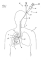
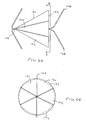
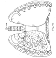
- Fig. 1 is a schematic view showing a system 10 for carrying out a pulmonary procedure on the lung L of a patient P.
- the system 10 is exemplary only and includes a bronchoscope 12 having a steering mechanism schematically indicated at 14, a shaft 16, and a port 18 which provides access to one or more working channels of the bronchoscope.
- Fig. 1 shows a delivery device 20.
- the delivery device 20 is shown positioned in the bronchoscope 12 in order to deliver a flow control element 22.
- the bronchoscope 12 has been passed into the patient's trachea T and guided into the right bronchus 24.
- the delivery device 20 is then manipulated with respect to the bronchoscope 12 via steering mechanism 14 to control placement of the flow control element 22.
- the delivery device 20 is movable within a bronchoscope working channel 26 ( Fig. 8 ) and is guided into the desired location in the hollow structure, which in this case is a bronchiole 28.
- the bronchiole 28 feeds an upper lobe U of the lung L which represents a diseased lung portion.
- the delivery device 20 is placed through the side port 18 and into the working channel 26, the distal end 30 of the delivery device 20 is moved out of the working channel, and the flow control element 22 is secured in position in the bronchiole 28.
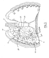
- Fig. 2 is an enlarged view of the patient's lungs L shown in Fig. 1 after the introducer 12 and delivery device 20 have been removed, the flow control element 22 being left in the bronchiole 28.
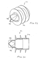
- the flow control element 22, shown in more detail in Fig. 3 is in the form of a valve with a valve member 32 supported by a ring 34.
- Fig. 2 also illustrates a second flow control element 22A placed in a bronchiole 28A that feeds a lower lobe LL of the lung.
- the flow control element 22A includes a valve member 32A and a support ring 34A and reduces or prevents fluid from being inhaled into the hyper-expanded tissue of the lower lobe LL. It will be understood that any number of flow control elements may be used in a given procedure.
- the valve member 32 is a duckbill-type valve and has two flaps defining an opening 36.
- the valve member 32 is shown in a flow-preventing orientation in Fig. 3 with the opening 36 closed.
- the valve member 32 is configured to allow fluid flow in a first direction (along arrow A) while controlling fluid flow in a second direction (along arrow B).
- fluid flow in the direction of arrow B is controlled by being completely blocked by valve member 32.
- the first and second directions in which fluid flow is allowed and controlled, respectively, are preferably opposite or substantially opposite each other, for example, as shown in the Figures. It will be appreciated, though, that the invention may be practiced with the first and second directions different but not opposite each other.
- valve member 32 of the flow control element 22 controls fluid flow by completely blocking such flow in the second direction.
- valve member 32 effectively functions as a one-way valve.
- Alternative embodiments of the invention utilize flow control elements that controls fluid flow in the second direction without completely blocking such flow.
- Fig. 4 shows an exemplary flow control element 38 constructed according to an alternative embodiment of the invention that limits, but does not block, fluid flow in at least one direction.
- the flow control element 38 comprises a valve member 40 supported by a ring 42.
- the valve member 40 is preferably a duckbill-type valve having a similar construction to that of the valve member 32, except that the flaps 44 are formed, secured, oriented or otherwise configured to maintain a flow opening 46 when in their flow-controlling (as opposed to flow-allowing) orientation.
- the opening 46 is sized and configured to achieve desired flow characteristics through the flow control element 38.
- Fig. 4 shows only one way to achieve limited fluid flow in a given direction.
- the specific manner in which flow control is obtained may vary according to the invention, e.g., by varying the number, size, shape or position of the flow openings on the flow control element.
- the flow control element may be constructed to provide a pumping action that aids in moving gas or liquid within a hollow structure, such as a bronchiole.
- a mechanical pumping action is produced that may be used to move the gas or liquid to further deflate the isolated region of the lung.
- Fig. 5 shows an exemplary flow control element 50 constructed according to this embodiment and including a pair of valve members 52, 54 supported in series by a ring 56.
- the valve members 52, 54 each include a pair of flaps defining a valve opening (the valve members being shown in their closed, fluid flow blocking orientation in Fig. 5 ).
- a chamber 58 is defined between the valve members 52, 54 and produces a pumping effect on the fluid flowing through the flow control element 50.
- the chamber would collapse and expand with movement of the bronchiole (or other hollow structure in which it is inserted) to pump fluid from the diseased lung tissue.
- the valve member 54 is coupled to a bellows 60 to enhance the pumping action and/or to control the amount of force needed to open the valve member.
- the wall 62 defining the chamber 58 is secured to the ring 56 so that the chamber 58 occupies the entire interior of the ring 56.
- the flow control element 50 may have a different configuration wherein the chamber 58 is defined by an air pocket located within the wall 62. This may prevent fluid collecting in the chamber 58.
- a power-driven pump may be used to draw fluid out of the lungs, e.g., a miniature battery-powered electric pump, or pumps that use physical or chemical characteristics, e.g., a change in air temperature, presence of an additional gas or liquid, change in pH, etc., to generate pumping force that evacuates air and mucous.
- Fig. 6 shows yet another alternative flow control element 70 including a valve member 72 comprising a pair of flaps defining an opening, and ring 74 supporting the valve member 72.
- the valve member 72 is a duckbill-type valve that permits fluid flow in a first direction but prevents flow in a second direction.
- the ring 74 in this embodiment comprises a stent 76 having struts 78 to enhance fixation of the flow control element 70 in the hollow body structure (not shown).
- the valve member 72 may be attached to the stent 76 by any suitable means, e.g., molded to the stent, suture, fasteners, adhesives, etc.
- the stent 76 is movable between collapsed and expanded ( Fig. 6 ) orientations to enable easy delivery and deployment.
- the flow control element 70 including stent 76 may be collapsed and held in a sheath for delivery through a relatively small space, for example, the working channel of a bronchoscope.
- a bronchoscope has a diameter of about 6 or 7 mm, while the working channel has a diameter of about 2 or 3 mm.
- Utilizing a collapsible flow control element may also be useful in introducing the flow control element through an small opening formed in the patient's thorax.
- Figs. 7 and 8 show in detail the bronchoscope 12 and the flow control element delivery device 20 described above in connection with Fig. 1 .
- the bronchoscope 12 has an eyepiece 80 which is used to visualize the trachea and the various pathways of the lung during deployment of the flow control element 22.
- the bronchoscope 12 may be provided with a camera/recorder, an aspiration/irrigation system, or other auxiliary features.
- the steering mechanism 14 may comprise cables that move the distal tip of the bronchoscope shaft 16 over a desired angular range, for example, 0° through 180°.
- Fig. 8 shows the distal portion 30 of the bronchoscope 12 including the working channel 26 (which communicates with the side port 18), one or more fiber optic light guides 81, and a lens 82 for transmitting images to the eyepiece 80.
- Fig. 9 shows the delivery device 20 to include a handle 84, an actuator 86, a support shaft 87 and a sheath 88.
- the delivery device 20 will be described in connection with delivering the flow control element 70 of Fig. 6 , although it will be understood that it may be used to deliver alternative flow control elements.
- the flow control element 70, and in particular the stent 76 is collapsed to a low profile orientation and then mounted on the shaft 87.
- the sheath 88 is moved distally from the position shown in Fig. 9 until it covers the stent body 76 (and the valve member 72, if desired) to maintain the flow control element 70 collapsed.
- the shaft 87 and sheath 88 are then passed into the side port 18 and working channel 26 of the bronchoscope 12 and guided to a desired location in the lung.
- the actuator 86 is used to remove the sheath 88 from the flow control element 70 which allows the stent 76 to expand.
- Stent 76 is preferably formed of a self-expanding material, e.g., nitinol. In this case the flow control element 70 immediately expands and engages the tissue upon retraction of sheath 88.
- the stents could rely on a mechanism such as a balloon or heat activation to expand in use.
- the flow control element of the invention may be guided to and positioned at a desired location in the pulmonary system, such as the bronchiole 28 shown in Figs. 1 and 2 , by various delivery devices or systems.
- a desired location in the pulmonary system such as the bronchiole 28 shown in Figs. 1 and 2
- various delivery devices or systems For example, guidewire-based systems, introducer sheaths, cannulae or catheters, etc., may be used to deliver the treatment element in a minimally invasive manner.
- the above-described method for using a bronchoscope to introduce the flow control element may be modified by placing an introducer sheath over the bronchoscope. The sheath provides access should the bronchoscope need to be removed from patient's body, for example, in order to place a different size flow control element.
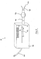
- Fig. 10 shows somewhat schematically an exemplary device for determining the size of a hollow structure in a patient's body, for example, a bronchiole in a lung.
- the device 90 includes a housing 92, shaft 94, positioning element, 96 and measuring elements 98.
- the measuring elements 98 have tips 100 that are moved into contact with the wall of the hollow structure, such as the inner surface of a bronchiole (not shown).
- the device 90 is calibrated so that when tips 100 of measuring elements 98 engage the wall of the bronchiole the indicator 102 displays the approximate size of the bronchiole.
- An electrical coupling 104 powers the device 90.
- the positioning element 96 is optional and may be used to fix the position of the measuring elements 98 within the bronchiole so as to obtain more precise measurement.
- the illustrated element 96 is an inflatable balloon, although other elements could be used to center and hold the shaft 96 within the bronchiole. Any suitable means may be used for ensuring that the measuring elements 98 do in fact contact the bronchiole wall in order to provide a true reading.
- the measuring elements 98 may be moved distally (to the right in Fig. 10 ) until a visual indicator indicates that the tips 100 are in contact with tissue. Alternatively, a change in electrical resistance may be used to confirm contact between the measuring elements 98 and tissue.
- the device 90 is merely representative of the various means that may be used to determine the size of a hollow body structure.
- the shaft 94 of the measuring device 90 is passed through the bronchoscope working channel 26 and delivered to the site.
- the device 90 is then operated as described above to determine the approximate size of the bronchiole.
- the degree of precision with which the size of the hollow structure is measured will depend on the procedure being performed and user preference.
- the device 90 is removed from working channel 26, and delivery device 20 is inserted into the channel to deploy the flow control element in the bronchiole.
- a flow control element It may in some instances be necessary or desirable to remove a flow control element from a hollow structure in which it has been deployed. As an example, it may be the case that placement of a flow control element for a given period of time effects beneficial results on the diseased lung tissue.
- the time during which the diseased tissue is deflated and decompressed may allow the tissue to regain some elasticity as a result of being temporarily inactive. After the tissue has regained some or all of its elasticity, it would be better to remove the flow control element and allow the tissue to function efficiently.
- the flow control element is preferably not removed before the tissue has a sufficient chance to recover.
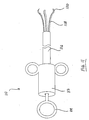
- Fig. 11 shows a device 110 comprising a handle 112, an actuator 114, a shaft 116 and one or more removal components 118.
- the components 118 preferably have tips 120 configured to grasp a flow control element in order to remove the element from surrounding tissue.
- the shaft 116 of the device 110 is passed into a patient's trachea (not shown) and is guided to the previously-deployed flow control element; for example, the shaft 116 may be introduced through the working channel of a bronchoscope in the same manner as the delivery device 20.
- the removal components 118 are preferably collapsed within shaft 116 while the shaft is guided to the site. The components 118 are then extended into contact with the wall of the bronchiole. The tips 120 are used to grasp and remove the flow control element from the bronchiole.
- the flow control element of the invention is secured in position in the hollow structure, such as bronchiole 28, so as to remain in place during breathing.
- the exterior of the flow control element may be configured along all or part of its exterior to aid in fixing the element in place, for instance, as schematically indicated by reference numeral 48 in Figs. 3 and 4 .
- the fixation structure 48 may comprise adhesives, tissue growth-inducing substances, fasteners, staples, clips, suture, stents, balloons, Dacron® sleeves, sintered, etched, roughened, barbed or alternatively treated surfaces, etc.
- Placement of a flow control element constructed according to the invention in a patient's pulmonary system achieves several benefits.
- the element when deployed in the bronchiole 28 as shown in Figs. 1 and 2 , the element allows exhalation but prevents inhalation.
- the flow control element 22 thus limits or prevents the inhalation of additional fluid into the diseased lung portion. This is beneficial because it prevents further enlargement of the hyper-expanded tissue, which in turn maintains more room in the pleural space for healthy lung tissue.
- the flow control element 22 also allows any air being naturally exhaled by the patient (as well as any liquid, if present) to exit the lung, thereby deflating or decompressing the tissue.
- the fluid is preferably permitted to flow unimpeded from the lung, but it may instead be metered or regulated in order to control deflation.
- the flow control element 22 serves as a blocking element 122 which blocks air in the inhalation direction.
- the blocking element 122 has a valve 124 which permits air flow in an exhalation direction but prevents air flow in the inhalation direction.
- the valve 124 may be any suitable valve such as any of the valves described herein.
- the valve of the invention is a duckbill valve.
- Figs. 13 and 16 show the valve 124 having a first lip 126 and a second lip 128 which engage one another in the closed position.
- the term valve as used herein may also refer to a check valve which permits flow in one direction but prevents flow in the other direction.
- valves described herein are used with various aspects of the invention, other aspects of the invention may be practiced by blocking flow in both directions.
- the devices and methods for accessing the isolated part of the lung may be used with devices which block air flow in both directions.
- flow in the exhalation direction may be regulated in another manner as described herein rather than simply with the valve.
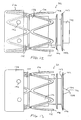
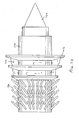
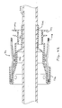
- the flow control element 22 has an expandable support structure 130.
- the support structure 130 is metallic and preferably a superelastic material such as nitinol.
- the support structure 130 is formed by cutting, etching or otherwise removing material from a tube to form openings 132 as is generally known in the art of forming small, metallic tubes such as stents.
- the support structure 130 may be made in any other suitable manner and with other suitable materials.
- the support structure 130 may be a nitinol tube which is laser cut to have six diamond-shaped openings 132.
- the flow control element 22 has a body 134 coupled to the support structure. 130.
- the body is preferably molded silicone or urethane but may be any other suitable material.
- the valve 124 is mounted to the body 134 and may be integrally formed with the body 134 as described below.
- the body 134 may be attached to the support structure 130 in any suitable manner.
- the body 134 may be positioned in the support structure 130 and an end 136 everted over an end 138 of the support structure 130.
- the everted end 136 is attached to the rest of the body 134 through the openings 132 in the support structure 130 at connections 140 with an adhesive, adhesive rivet, heat weld or any other suitable method.
- An advantage of coupling the body 134 to the support structure 130 with the connections 140 is that the support structure 130 and body 134 may collapse and expand somewhat independently since the connections 140 are free to move in the openings 132.
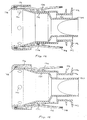
- the flow control element 22 may also have a sealing portion 142 which forms a seal with the wall of the pulmonary passage.
- the sealing portion 142 is attached to the body 134 separately ( Fig. 14 ) but an illustratory example is also shown integrally formed with the body 134 and valve 124 ( Fig. 15 ).
- An advantage of the flow control element 22 is that a substantial portion of the element 22, such as the body 134 and valve 124, are integrally formed.
- the valve 124, valve body 134 and sealing portion 142 are all integrally formed.
- the sealing portion 142 extends around the valve 124 but is not coupled directly to the valve 124 so that the valve 124 is not subjected to forces exerted on or by the sealing portion 142.
- the sealing portion 142 extends from a tube 144 positioned around the valve 124.
- the sealing portion 142 forms a ring 146 around the body 134.
- the ring 146 is made of a resilient, elastomeric material which improves sealing with the wall of the pulmonary passage.
- the ring 146 may have any suitable shape such as straight, tapered, angled or could have frustoconical surface 143 which angles the ring 146.
- the sealing portion 142 preferably has at least two sealing portions 142, and preferably three, which each have a different diameter to seal with different size passages. In this manner, the device may be used within a given size range.
- the ring 142 also may be designed to deflect to permit exhalation air to pass.
- valve 124 will, of course, open to permit air to escape, however, the pressure force on the valve 124 can be reduced if the sealing portion 142 also opens to permit further venting of the isolated portion of the lung.
- various other structures may also be used to provide valves which cooperate with the wall of the pulmonary passageway to permit venting of the isolated area.
- the body 134 is coupled to the support structure 130 to provide an exposed part 135 of the support structure 130 which helps to anchor the device.
- the term exposed part shall mean a part of the support structure 130 not covered by the body 134.
- the exposed part 135 may be covered by another material so long as it is not covered by the body 134.
- the exposed part 135 of the support structure 130 may form anchoring elements 148 which anchor the support structure 130.
- the anchoring elements 148 are preferably v-shaped to improve anchoring.
- the anchoring elements 148 may also be barbs or the like.
- the flow control device 22 may also be angled, tapered or flared so that one end 151 is larger than the other 149.
- any other shape, such as a cylinder or tube flared at both ends may be used without departing from many aspects of the invention.
- the element 22 has a valve 150 which has first and second lips 152, 154 which engage one another in a closed position.
- the first lip 152 is preferably stiffer than the second lip 154 so that the first lip 152 biases the second lip 154 closed.
- the first lip 152 may be made stiffer than the second lip 154 in any manner such as by using a thicker layer of the same material, a stiffer material for the first lip, or by simply adhering or attaching a stiffener 156 to the first lip 152.
- the first and second lips 152, 154 are preferably formed by a tube of material with the stiffener 156 attached to one side to form the first lip 152.
- the first and second lips 152, 154 are also preferably curved as shown in Fig. 18 .
- the element 22 is preferably made of molded silicone or urethane although any other suitable material may be used.
- the valve 150 also has reinforcing elements 155 at the lateral edges to further support the lips 152, 154.
- the valve 150 may, of course, have either the elements 155 or stiffener 156.
- the sealing portion 142 is not shown for clarity, the sealing portion 142 is also be provided.
- FIG. 19 another flow control element 22 is shown wherein the same or similar reference numbers show the same or similar structure.
- the flow control element 22 has the valve 124 and a number of sealing portions 142.
- the valve 124, sealing portion 142 and body 134 are integrally formed of a resilient material such as molded silicone or urethane.
- a resilient material such as molded silicone or urethane.
- the flow control element 22 may also have reinforcing element 158 such as a helical coil 160.
- the flow control element 22 has a sealing portion 142 which has a helical shape.
- the element 22 is rotated so that the helical shape of the sealing portion 142 engages the wall to anchor the element 22.
- any of the flow control elements of the present invention may also be used with a sealant 162, such as an adhesive, which seals and/or anchors the device.
- a sealant 162 such as an adhesive, which seals and/or anchors the device.
- the sealant 162 is positioned on the exterior of the device between the sealing portions 142.
- the sealant 162 is preferably a viscous substance which is applied to the exterior surface of the device before introduction.
- the sealant 162 may be an adhesive which also helps to anchor the device.
- the use of the sealant 162 may be used with any of the devices described herein.
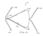
- the flow control element 22 has a support structure 164 which anchors a valve 166.
- the structure 164 has anchoring elements 168, preferably two, on each side of the valve 166.
- the anchoring elements 168 preferably pierce the wall to anchor the device.
- the anchoring element 168 are formed by two wires attached together.
- any other suitable structure may be used for the structure 164 such as a stent-like structure or an expandable ring with barbs.
- the valve 164 cooperates with the wall of the pulmonary passageway to vent the isolated area.
- the valve 164 is generally conical, however, any other shape may be used.
- the valve 164 may engage the pulmonary wall with a number of different configurations without departing from the scope of the invention, thus, the following preferred embodiments do not limit the scope of the invention.
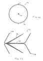
- the valve 164 is elastic and yields to permit expiratory air to pass between the valve and the wall of the passageway. Referring to Fig. 22 , the valve 164 is thinner near an end engaging the wall W so that the end of the valve 164 is more flexible.
- the device has a valve 170 with a number of sections 172 with each section 172 forming a seal with the wall of the pulmonary passage.
- the sections 172 are separated by wires 174 which provide a resilient structure.
- the device may be formed with any number of the sections 172 forming a valve structure 173 with the wall of the pulmonary passage.
- FIG. 26 and 27 still another flow control element 22 also not part of the invention is shown wherein the same or similar reference numbers refer to the same or similar structure.
- the element 22 has a flap valve 174 which opens to permit expiratory air to pass.
- the valve 174 is also generally conical.
- the term generally conical as used herein means that the cone may diverge from a cone in that the walls may be slightly curved, have a number of sections, or a seam, flap or fold while still being generally cone-shaped.
- a slit or seam 178 which opens to permit expiratory air to pass.
- the slit or seam 178 may also be oriented and configured like a slit valve without departing from the scope of the invention.
- the device has the valve 124 but may have any other suitable valve.
- the device has flexible bristles180, preferably more than 10, 20 or even 30 bristles 180, which anchor the device in the pulmonary passageway.
- the bristles 180 are preferably angled to resist forces in the expiratory direction so that pressure forces, such as forces developed during coughing, cannot dislodge the device.
- the bristles 180 may be used with the sealant 162 to provide an airtight seal.
- FIG. 31 still another flow control element 22 is shown which includes a sealing element 182, such as a ball 184, biased toward the closed position to form a ball valve 183, not part of the claimed invention.
- the sealing element 182 is biased with a spring 186 although any other biasing element may be used.
- the device has a body 188 with the sealing portion 142.
- the body 188 has an opening 190 through which air may pass when the sealing element 182 opens.
- FIG. 32 still another device is shown which has a blocking element 185 rather than the ball 184 of Fig. 31 to form a poppet valve 187.
- FIG. 33 and 34 still another flow control element 22 not part of the invention is shown.
- the device has a valve 186 which has at least three leaflets 188 which engage one another in the closed position.
- FIG. 35 and 36 still another device (out of the invention) is shown having a flap valve 190.
- the flap valve 190 deflects to permit expiratory air to pass.
- the flap 190 is preferably made of an elastomeric material.
- the flap 190 is attached to a support strut 192 extending across an open end 194 of the body 196.
- the body 196 has the sealing portion 142 which is preferably formed by ribs extending around the body 196.
- FIGs. 37 and 38 another flap valve 198 is shown.
- the flap valve 198 is attached to the body at hinge 199.
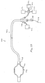
- the system 200 is, of course, useful for delivering any of the devices described herein or any other suitable device.
- the system 200 includes a delivery element 202 having a first lumen 204 and a second lumen 206.
- the delivery element 202 also has an expandable member 208, such as a balloon 210, which is coupled to the second lumen 206 for inflating the balloon 210 with a source of inflation fluid or gas 212.
- the device is loaded into the end of the delivery element 202 and a pusher 214 may be used to move the device, such as the device of Figs. 12-16 , out of the delivery element 202.
- the first lumen 204 has an enlarged end which forms a capsule 215 which contains the device.
- the element 202 may also be advanced over a guidewire 217 or the like in a conventional manner.
- the delivery element 202 may also be used to remove air, and even fluid if necessary, from the isolated portion of the lung.
- the expandable member 208 is expanded to isolate a portion of the lung and suction is applied to deflate the lung.
- the isolated portion of the lung may be deflated with the device contained within the delivery element 202 or may be deflated after delivery of the device.
- An advantage of using the valves of the present invention is that air can be drawn through the valve even after the valve has been deployed. Referring to Fig. 40 , the valve 124 also may remain operational even when in the collapsed position. Thus, the isolated portion of the lung may also be suctioned when the device is contained in the first lumen.
- the second lumen 206 of the delivery element 202 may be substantially independent of the outer wall of the delivery element 202 so that the stiffness of the device is reduced as compared to an integrally formed multi-lumen device.
- the second lumen 206 is formed by a separate tube 209 passing through the first lumen 204.
- the delivery element 202 has an outer diameter which is 80-120%, more preferably 90-110%, of the minimum placement size of the device.
- the isolated portion of the lung may be accessed after implantation of a device for subsequent medical treatments.
- the valve may be penetrated with the delivery device 202, or similar device, to deliver and/or evacuate gas or liquid.
- the device is coupled to a source of fluid 211, such as an antibiotic or antisurfactant, which is delivered and, if necessary, evacuated from the lung.
- a gas such as an antibiotic gas, may also be delivered from a source of gas 213 to the isolated area to reach distal portions of the isolated area.
- the device 202 may be coupled to a vacuum source 215 for deflating the isolated portion or evacuating mucous or other fluids from the isolated portion of the lung.
- a valve 216 is provided for selectively coupling the first lumen 204 to any of the source of fluid 211, gas 213 or vacuum 215.
- the device 202 may form a tight seal with the valve 124 so that the isolated portion remains deflated during the procedure.
- the device 202 may have the expandable element 208, such as the balloon 210, for occluding the pulmonary passageway on either side of the valve 124 to achieve isolation at any particular location in the pulmonary passageway distal or proximal to the valve 124.
- An advantage of the present invention is that the isolated portion may be deflated after implantation of the valve without penetrating the valve.
- the device may be positioned proximal to the valve and the expandable element expanded to occlude the pulmonary passageway. Suction is then applied through the device so that a low pressure area develops between the valve and occluding member. When the pressure differential is large enough, the valve will open to vent and deflate the isolated portion of the lung. This process can be continued in a controlled manner until the desired amount of deflation is achieved or when a target pressure has been reached. When suction is stopped, the valve will close to isolate part of the lung.
- the delivery device may also be used as a diagnostic tool.
- the balloon may be deflated momentarily so that the isolated area between the balloon and valve increases in pressure. If the pressure decreases after the balloon is inflated again it may indicate that the valve is not sealing properly since the air may be passing around or through the valve and into the isolated portion.
- An alternative diagnostic would be to pressurize the space between the valve and expandable member. The pressure response can then be monitored to determine if the valve provides an adequate seal.
- the devices and valves of the present invention provide the ability to prevent inflation of diseased areas of the lung while also permitting venting of these portions of the lung.
- the valves preferably open with a relatively small pressure differential across the valve.
- the valve open with a pressure differential of no more than 2.5kPa (10 inches water) more preferably no more than 1.25kPa (5 inches water) and most preferably no more than 0.25kPa (1 inch water).
- the valves and valve elements of the present invention may open with relatively small pressure differentials, valves and valve elements not of the invention may also have higher opening pressures.
- the valves may also be designed to open only for high pressure events such as coughing.
- the opening pressure, or differential pressure is at least 6.23kPa (5 inches water) but still no more than 30kPa (120 inches water).
- coughing may be induced to increase the driving force and expiratory pressure to vent the isolated portions of the lung.
- the flow control elements of the invention permit the diseased tissue to gradually deflate, either under the patient's own power or by applying relatively gentle suction for a given period of time.
- the suction may be applied intermittently or continuously by any suitable means.
- a suction catheter could be passed through the flow control element in the bronchiole and into the distal tissue.
- the flow control element for example, a valve member, would preferably seal around the catheter in order to prevent fluid moving distally past the valve.
- the invention thus provides significant benefits as it permits fluid to be evacuated from the alveoli without collapsing the floppy walls of the narrow airways leading to them, problem with common lung diseases such as emphysema and COPD, as discussed above. Accordingly, the invention facilitates removal of more fluid from the diseased lung tissue than prior art approaches, the effect of which is more plural space available to the healthy lung tissue.
- using the invention to deflate the diseased lung tissue for a selected period of time, e.g., one month, may have beneficial results on the tissue by temporarily removing it from the respiratory circuit.
- the flow control element is preferably removed before the tissue begins to necrose, but is left in place a sufficiently long enough time that the tissue will not revert to its floppy, toneless state when the element is removed.
- some possible substances with which the invention may be used include gene therapy or angiogenesis factors for lung repair or re-establishment of tissue elasticity; growth factors; anti-growth or anti-angiogenesis factors (or substances to cause necrosis or apoptosis) to prevent re-establishment of air and blood flow; antibiotics to prevent infection; anti-inflammatory agents including steroids and cortisones; sclerosing drugs or materials to promote rapid healing, for example, to allow earlier removal of the flow control element; agents for absorbing remaining fluids; and sealing substances for enhancing isolation of the diseased tissue.
- the portion of the lung being treated may be deflated over time through repeated natural inhalation and exhalation with the flow control element in place.
- a vacuum source may be coupled to the flow control element to draw fluid out of the diseased tissue in the manner discussed above. This deflation of the diseased portion may be performed alone or in conjunction with delivering biological substances.
- the pressures used to suction the lung portion are preferably low to avoid collapsing the walls of the narrow airways.
- the flow control element comprises a valve
- the valve may comprise an annulus or support ring formed of any suitable metal or synthetic material, with the valve member being formed of silicone, natural rubber, latex, polyurethane, polytetrafluoroethylene, a thermoplastic elastomer, tissue, etc.
- the valve member may be integral with the support ring or it may be a separate member attached thereto by suitable means, e.g., suture, adhesives, mechanical fasteners, etc.
- suitable means e.g., suture, adhesives, mechanical fasteners, etc.
- the specific characteristics of the flow control element may be varied depending on the particular application. It may be desirable to provide multiple flow control elements with valve members that require different exhale pressures to open, for example, in order to allow treatment of patients who generate different exhalation pressures.
- the different flow control elements could be provided in a kit and be distinguished from each other based on required opening force, size, material, etc.
- the kit could include a color or other coding system to indicate these factors.
- the flow control elements of the invention are preferably constructed so as to require a relatively low opening force in order to allow fluid flow in the first direction.
- Emphysema patients typically exhale a small quantity of low-pressure fluid.
- the invention preferably allows any such fluid to escape via the flow control element in the hollow structure.
- the flow control element is designed to open and allow flow in the first direction in response to any positive pressure generated by the patient.
- the flow control element will open to allow fluid to escape the tissue. It will nonetheless be recognized that the particular force required to open the flow control element may be varied depending on exhalation pressures associated with the intended patient population.
- inventive devices may include removable or detachable components, and may comprise disposable or reusable components, or a combination of disposable and reusable components.
- inventive devices may be practiced with one or more of the steps specifically illustrated and described herein modified or omitted.
- the invention is not limited to treating lung diseases as is shown in the Figures, although that is a preferred application.
- the invention may be used in any pulmonary or non-pulmonary procedure in which it is desirable to allow fluid flow in a first direction and control fluid flow in a second, different direction within a hollow structure.
- a minimally invasive, endobronchial approach is shown in the Figures, other approaches may used, for example, an open surgical procedure using a median sternotomy, a minimally invasive procedure using a mini thoracotomy, or a still less invasive procedure using one or more ports or openings in the thorax, etc.
Abstract
Description
- The present invention relates generally to methods and devices for use in performing pulmonary procedures, and more particularly, procedures for treating various diseases of the lungs.
- Pulmonary diseases such as emphysema and chronic obstructive pulmonary disease (COPD) reduce the ability of one or both lungs to fully expel air during the exhalation phase of the breathing cycle. The diseased lung tissue is less elastic than healthy lung tissue, which is one factor that prevents full exhalation of air. During breathing, the diseased portion of the lung does not fully recoil due to the tissue being less elastic. Consequently, the diseased (e.g., emphysematic) lung tissue exerts a relatively low driving force, which results in the diseased lung expelling less air volume than a healthy lung. The reduced air volume exerts less force on the airway which allows the airway to close before all air has been expelled, another factor that prevents full exhalation.
- The problem is further compounded by the diseased, less elastic tissue that surrounds the very narrow airways that lead to the alveoli (the air sacs where oxygen-carbon dioxide exchange occurs). This tissue has less tone than healthy tissue and is typically unable to maintain the narrow airways open until the end of the exhalation cycle. This traps air in the lungs and exacerbates the already-inefficient breathing cycle. The trapped air causes the tissue to become hyper-expanded and no longer able to effect efficient oxygen-carbon dioxide exchange. Applying suction to these narrow airways (a procedure proposed in the literature for deflating the diseased portion of the lung) may collapse the airways due to the surrounding diseased tissue, thereby preventing successful fluid removal.
- In addition, hyper-expanded lung tissue occupies more of the pleural space than healthy lung tissue. In most cases, a portion of the lung is diseased while the remaining part is healthy and therefore still able to efficiently carry out oxygen exchange. By taking up more of the pleural space, the hyper-expanded lung tissue reduces the amount of space available to accommodate the healthy, functioning lung tissue. As a result, the hyper-expanded lung tissue causes inefficient breathing due to its own reduced functionality and because it adversely affects the functionality of adjacent healthy tissue.
- Lung reduction surgery is a conventional method of treating lung diseases such as emphysema. A diseased portion of the lung is surgically removed which makes more of the pleural space available to accommodate the functioning, healthy portions of the lung. The lung is typically accessed through a median sternotomy or small lateral thoracotomy. A portion of the lung, typically the upper lobe of each lung, is freed from the chest wall and then resected, e.g., by a stapler lined with bovine pericardium to reinforce the lung tissue adjacent the cut line and also to prevent air or blood leakage. The chest is then closed and tubes are inserted to remove air and fluid from the pleural cavity. The conventional surgical approach is relatively traumatic and invasive, and, like most surgical procedures, is not a viable option for all patients.
- More recently proposed treatments include the use of devices that employ RF or laser energy to cut, shrink or fuse diseased lung tissue. Another lung volume reduction device utilizes a mechanical structure that is used to roll the lung tissue into a deflated, lower profile mass that is permanently maintained in a compressed condition. As for the type of procedure used, open surgical, minimally invasive and endobronchial approaches have all been proposed. Another proposed device (disclosed in publication no.
WO 98/48706WO 01/13839 US 5392775 illustrates other valve systems used in tracheostong systems. - The search for new and better treatments underscores the drawbacks associated with existing pulmonary procedures. Accordingly, there is a need in the art for improved methods and devices for performing pulmonary procedures, and in particular, treating lung diseases such as emphysema.
- A method for treating a patient's lung is discussed. The method includes steps of selecting a hollow structure in a patient's lung, the hollow structure defining a pathway for conducting fluid flow in at least first and second directions, and allowing fluid flow within the pathway in the first direction while controlling fluid flow in the second direction.
- Another example is given for a method for treating a patient's lung. This method includes steps of providing a valve which allows fluid flow in a first direction and limits fluid flow in a second direction, and positioning the valve at a desired location in a lung of a patient with the first direction corresponding to an exhalation direction and the second direction corresponding to an inhalation direction.
- Another example is given of a method for treating a patent's lung that includes steps of providing a flow control element that limits fluid flow in at least one direction, positioning the flow control element at a location in a lung of a patient with the one direction substantially corresponding to an inhalation direction, and removing the flow control element after a period of time.
- Another exemplary method for treating a patent's lung, comprises steps of selecting a hollow structure in a patient's lung, the hollow structure defining a pathway for conducting fluid flow in at least first and second directions, applying suction to draw fluid through the pathway in the first direction, and substantially preventing fluid flow through the pathway in the second direction.
- The invention provides a system for treating a patient's lung. The system includes a flow control element sized and configured to be positioned in a hollow structure located in a patient's lung, the flow control element including a valve member that permits fluid flow in a first direction while substantially preventing fluid flow in a second direction. A delivery device is sized and configured to be guided to and positioned in or adjacent the hollow structure, and the flow control element is removably mounted on the delivery device. This valve is a duckbill valve.
- A system for treating a patient's lung is also described. The system includes a measuring device for determining the approximate size of a hollow structure in a patient's lung, and a flow control element sized and configured to be positioned in a hollow structure located in a patient's lung, wherein the flow control element allows fluid flow in a first direction but substantially prevents fluid flow in a second direction.
- In another example the invention provides a system for treating a patient's lung. This system includes a flow control element sized and configured to be positioned in a hollow structure located in a patient's lung, wherein the flow control element allows fluid flow in a first direction but substantially prevents fluid flow in a second direction, and a removal device for removing the flow control element from the hollow structure subsequent to positioning the flow control element in the hollow structure.
- In another example, a blocking element is coupled to a delivery element. The blocking element is advanced to a location in a patient's lung. An expandable member is expanded to occlude a pulmonary passageway and air is then withdrawn from the lung. The blocking element is released to block air flow into the isolated portion of the lung. The blocking element may also be a valve. The expandable member may be carried by the delivery element or by a separate element.
- In still another example, a device is advanced through the blocking element after implantation of the blocking element. A procedure, such as delivery or evacuation of fluids or liquids, may then be performed with the device. The device is then removed with the blocking element again preventing air from passing in the inhalation direction. The blocking element may also be a valve which permits air flow in an expiratory direction.
-
-
Fig. 1 is an elevation view schematically showing a system constructed according to one embodiment of the invention, the system being used to perform a pulmonary procedure on a patient; -
Fig. 2 is an enlarged elevation view of the lungs of the patient shown inFig. 1 along with the system of the invention; -
Fig. 3 is an enlarged elevation view, in section, of a flow control element forming part of the system shown inFig. 2 , wherein the flow control element allows fluid flow in a first direction but blocks fluid flow in a second direction; -
Fig. 4 is an enlarged elevation view, in section, of an alternative flow control element that allows fluid flow in a first direction but blocks fluid flow in a second direction; -
Fig. 5 is an enlarged elevation view, in section, of another alternative flow control element; -
Fig. 6 is an enlarged elevation view, in section, of still another alternative flow control clement; -
Fig. 7 is a perspective view of an introducer used with the invention; -
Fig. 8 is an enlarged perspective view of a portion of the introducer shown inFig. 7 ; -
Fig. 9 is a perspective view of a delivery device for delivering a flow control element to a selected location in a patient's lung; -
Fig. 10 is a perspective view of a measuring device for determining the size of a hollow structure prior to disposing a flow control element in the structure; and -
Fig. 11 is a perspective view of a removal device for removing a flow control element that has already been positioned in a hollow structure. -
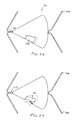
Fig. 12 is a side view of another flow control element. -
Fig. 13 is another side view of the flow control element ofFig. 12 . -
Fig. 14 is a cross-sectional view of the flow control element ofFig. 12 . -
Fig. 15 is an alternative cross-sectional view of the flow control element ofFig. 12 . -
Fig. 16 is an isometric view of the flow control element ofFig. 12 altered to have a tapered shape. -
Fig. 17 shows another flow control element. -
Fig. 18 is an end view of the flow control element ofFig. 17 . -
Fig. 19 shows another flow control element. -
Fig. 20 shows still another flow control element. -
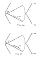
Fig. 21 is a side view of another flow control element, not part of the claimed invention. -
Fig. 22 is a cross-section ofFig. 21 along line A-A. -
Fig. 23 is a longitudinal cross-section ofFig. 21 . -
Fig. 24 is an alternative embodiment of the flow control device ofFig. 21 . -
Fig. 25 is a cross-section ofFig. 24 along line B-B. -
Fig. 26 shows another flow control element not part of the claimed invention with a flap valve in a closed position. -
Fig. 27 shows the flap valve ofFig. 26 in an open position. -
Fig. 28 shows a slit valve in a closed position. -
Fig. 29 shows the slit valve in an open position. -
Fig. 30 shows a flow control element with bristles. -
Fig. 31 is a cross-sectional view of a ball valve, not part of the invention. -
Fig. 32 is a cross-sectional view of a poppet valve, not part of the invention. -
Fig. 33 shows a leaflet valve, not part of the invention. -
Fig. 34 is a cross-section of the leaflet valve ofFig. 33 . -
Fig. 35 shows another flap valve, not part of the invention. -
Fig. 36 is a cross-sectional view of the flap valve ofFig. 35 . -
Fig. 37 shows still another flap valve. -
Fig. 38 is a cross-sectional view of the flap valve ofFig. 36 . -
Fig. 39 shows a system for performing pulmonary procedures. -
Fig. 40 is a cross-sectional view of the distal end of the system ofFig. 39 . -
Fig. 41 illustrates access of the isolated portion of the lung through the flow control element of the present invention. -
Fig. 42 shows a device passing through the flow control element ofFigs. 12-15 with the valve sealing around the device. - The present invention provides devices for performing pulmonary procedures, for example, treating various lung diseases such as emphysema and COPD. One preferred embodiment of the invention provides a flow control element that allows fluid flow in a first direction and controls fluid flow in a second direction. As used herein, fluid means gas, liquid, or a combination of a gas(es) and liquid(s). In addition, controlled fluid flow, as used herein, means that the flow is altered in some manner, i.e., the flow is not unimpeded in the second direction. The specific manner in which fluid flow is controlled in the second direction depends on the construction of the flow control element. The flow control element may, for example, completely block, substantially block, limit, meter or regulate fluid flow in the second direction by a valve or other suitable structure.
- As an example, when positioned in a hollow structure in a patient's body, such as a bronchiole in one of the lungs, the flow control element is oriented to allow flow in the exhalation direction but prevent fluid flow in the inhalation direction. The flow control element has a valve member that opens during exhalation in order to deflate or decompress the isolated lung portion distal to the flow control element. This maintains the diseased tissue in a decompressed state which prevents further hyper-expansion of the tissue. The invention also permits slow decompression of the lung tissue over a short or extended period of time.
- The invention thus may be used to prevent fluid being drawn into one or more portions of a patient's lung. According to another aspect of the invention, a portion of the lung may be deflated by applying gentle suction (via the flow control element) to the hyper-expanded tissue without collapsing the walls of the narrow airways surrounded by diseased tissue. The suction draws air, liquid, mucous, etc.; out of the lung portion to evacuate the diseased tissue. It will be recognized that these and other aspects of the invention may be practiced independently or in conjunction with each other.
-
Fig. 1 is a schematic view showing a system 10 for carrying out a pulmonary procedure on the lung L of a patient P. It should initially be noted that suitable systems, methods or devices outside of those specifically described herein may be used to practice the invention. As such, the system 10 is exemplary only and includes abronchoscope 12 having a steering mechanism schematically indicated at 14, ashaft 16, and aport 18 which provides access to one or more working channels of the bronchoscope. -
Fig. 1 shows adelivery device 20. Thedelivery device 20 is shown positioned in thebronchoscope 12 in order to deliver aflow control element 22. Thebronchoscope 12 has been passed into the patient's trachea T and guided into theright bronchus 24. Thedelivery device 20 is then manipulated with respect to thebronchoscope 12 viasteering mechanism 14 to control placement of theflow control element 22. With reference toFigs. 1 and7-9 , thedelivery device 20 is movable within a bronchoscope working channel 26 (Fig. 8 ) and is guided into the desired location in the hollow structure, which in this case is abronchiole 28. For purposes of explanation, thebronchiole 28 feeds an upper lobe U of the lung L which represents a diseased lung portion. Thedelivery device 20 is placed through theside port 18 and into the workingchannel 26, thedistal end 30 of thedelivery device 20 is moved out of the working channel, and theflow control element 22 is secured in position in thebronchiole 28. -
Fig. 2 is an enlarged view of the patient's lungs L shown inFig. 1 after theintroducer 12 anddelivery device 20 have been removed, theflow control element 22 being left in thebronchiole 28. Theflow control element 22, shown in more detail inFig. 3 , is in the form of a valve with avalve member 32 supported by aring 34. It should be noted thatFig. 2 also illustrates a secondflow control element 22A placed in a bronchiole 28A that feeds a lower lobe LL of the lung. Theflow control element 22A includes a valve member 32A and asupport ring 34A and reduces or prevents fluid from being inhaled into the hyper-expanded tissue of the lower lobe LL. It will be understood that any number of flow control elements may be used in a given procedure. - Referring to
Fig. 3 , which shows theflow control element 22 in detail, thevalve member 32 is a duckbill-type valve and has two flaps defining anopening 36. Thevalve member 32 is shown in a flow-preventing orientation inFig. 3 with theopening 36 closed. Thevalve member 32 is configured to allow fluid flow in a first direction (along arrow A) while controlling fluid flow in a second direction (along arrow B). In this embodiment, fluid flow in the direction of arrow B is controlled by being completely blocked byvalve member 32. The first and second directions in which fluid flow is allowed and controlled, respectively, are preferably opposite or substantially opposite each other, for example, as shown in the Figures. It will be appreciated, though, that the invention may be practiced with the first and second directions different but not opposite each other. - As noted above, the
valve member 32 of theflow control element 22 controls fluid flow by completely blocking such flow in the second direction. As such, thevalve member 32 effectively functions as a one-way valve. Alternative embodiments of the invention utilize flow control elements that controls fluid flow in the second direction without completely blocking such flow. -
Fig. 4 shows an exemplaryflow control element 38 constructed according to an alternative embodiment of the invention that limits, but does not block, fluid flow in at least one direction. Theflow control element 38 comprises avalve member 40 supported by a ring 42. Thevalve member 40 is preferably a duckbill-type valve having a similar construction to that of thevalve member 32, except that theflaps 44 are formed, secured, oriented or otherwise configured to maintain a flow opening 46 when in their flow-controlling (as opposed to flow-allowing) orientation. Theopening 46 is sized and configured to achieve desired flow characteristics through theflow control element 38. - When the
flow control element 38 is in its flow-allowing orientation (not shown), theflaps 44 spread apart and allow essentially unimpeded fluid flow out of the diseased lung portion. When theflow control element 38 is in its flow-controlling orientation, as shown inFig. 4 , the flaps move together to defineopening 46 which allows a predetermined amount of fluid to be inhaled into the lung portion. This is in contrast to flowcontrol element 22 which blocks fluid flow into the lung when in a flow-controlling orientation. It will of course be recognized thatFig. 4 shows only one way to achieve limited fluid flow in a given direction. The specific manner in which flow control is obtained may vary according to the invention, e.g., by varying the number, size, shape or position of the flow openings on the flow control element. - According to another aspect of the invention, the flow control element may be constructed to provide a pumping action that aids in moving gas or liquid within a hollow structure, such as a bronchiole. For instance, when the lung distorts during inhalation and/or exhalation, a mechanical pumping action is produced that may be used to move the gas or liquid to further deflate the isolated region of the lung.
Fig. 5 shows an exemplaryflow control element 50 constructed according to this embodiment and including a pair ofvalve members 52, 54 supported in series by aring 56. Thevalve members 52, 54 each include a pair of flaps defining a valve opening (the valve members being shown in their closed, fluid flow blocking orientation inFig. 5 ). Achamber 58 is defined between thevalve members 52, 54 and produces a pumping effect on the fluid flowing through theflow control element 50. The chamber would collapse and expand with movement of the bronchiole (or other hollow structure in which it is inserted) to pump fluid from the diseased lung tissue. - The
valve member 54 is coupled to abellows 60 to enhance the pumping action and/or to control the amount of force needed to open the valve member. Thewall 62 defining thechamber 58 is secured to thering 56 so that thechamber 58 occupies the entire interior of thering 56. Theflow control element 50 may have a different configuration wherein thechamber 58 is defined by an air pocket located within thewall 62. This may prevent fluid collecting in thechamber 58. In addition, a power-driven pump may be used to draw fluid out of the lungs, e.g., a miniature battery-powered electric pump, or pumps that use physical or chemical characteristics, e.g., a change in air temperature, presence of an additional gas or liquid, change in pH, etc., to generate pumping force that evacuates air and mucous. -
Fig. 6 shows yet another alternativeflow control element 70 including avalve member 72 comprising a pair of flaps defining an opening, andring 74 supporting thevalve member 72. Thevalve member 72 is a duckbill-type valve that permits fluid flow in a first direction but prevents flow in a second direction. Thering 74 in this embodiment comprises astent 76 havingstruts 78 to enhance fixation of theflow control element 70 in the hollow body structure (not shown). Thevalve member 72 may be attached to thestent 76 by any suitable means, e.g., molded to the stent, suture, fasteners, adhesives, etc. Thestent 76 is movable between collapsed and expanded (Fig. 6 ) orientations to enable easy delivery and deployment. That is, theflow control element 70 includingstent 76 may be collapsed and held in a sheath for delivery through a relatively small space, for example, the working channel of a bronchoscope. (A typical bronchoscope has a diameter of about 6 or 7 mm, while the working channel has a diameter of about 2 or 3 mm.) Utilizing a collapsible flow control element may also be useful in introducing the flow control element through an small opening formed in the patient's thorax. -
Figs. 7 and 8 show in detail thebronchoscope 12 and the flow controlelement delivery device 20 described above in connection withFig. 1 . Thebronchoscope 12 has aneyepiece 80 which is used to visualize the trachea and the various pathways of the lung during deployment of theflow control element 22. Thebronchoscope 12 may be provided with a camera/recorder, an aspiration/irrigation system, or other auxiliary features. Thesteering mechanism 14 may comprise cables that move the distal tip of thebronchoscope shaft 16 over a desired angular range, for example, 0° through 180°.Fig. 8 shows thedistal portion 30 of thebronchoscope 12 including the working channel 26 (which communicates with the side port 18), one or more fiber optic light guides 81, and alens 82 for transmitting images to theeyepiece 80. -
Fig. 9 shows thedelivery device 20 to include ahandle 84, anactuator 86, asupport shaft 87 and asheath 88. For purposes of illustration, thedelivery device 20 will be described in connection with delivering theflow control element 70 ofFig. 6 , although it will be understood that it may be used to deliver alternative flow control elements. Theflow control element 70, and in particular thestent 76, is collapsed to a low profile orientation and then mounted on theshaft 87. Thesheath 88 is moved distally from the position shown inFig. 9 until it covers the stent body 76 (and thevalve member 72, if desired) to maintain theflow control element 70 collapsed. (This position of the sheath is omitted for clarity.) Theshaft 87 andsheath 88 are then passed into theside port 18 and workingchannel 26 of thebronchoscope 12 and guided to a desired location in the lung. Theactuator 86 is used to remove thesheath 88 from theflow control element 70 which allows thestent 76 to expand.Stent 76 is preferably formed of a self-expanding material, e.g., nitinol. In this case theflow control element 70 immediately expands and engages the tissue upon retraction ofsheath 88. Alternatively, the stents could rely on a mechanism such as a balloon or heat activation to expand in use. - The flow control element of the invention may be guided to and positioned at a desired location in the pulmonary system, such as the
bronchiole 28 shown inFigs. 1 and2 , by various delivery devices or systems. For example, guidewire-based systems, introducer sheaths, cannulae or catheters, etc., may be used to deliver the treatment element in a minimally invasive manner. The above-described method for using a bronchoscope to introduce the flow control element may be modified by placing an introducer sheath over the bronchoscope. The sheath provides access should the bronchoscope need to be removed from patient's body, for example, in order to place a different size flow control element. Deployment of the device is preferably carried out by first determining the approximate size of the target lumen, i.e., the hollow structure in which the flow control element will be placed.Fig. 10 shows somewhat schematically an exemplary device for determining the size of a hollow structure in a patient's body, for example, a bronchiole in a lung. The device 90 includes ahousing 92,shaft 94, positioning element, 96 and measuringelements 98. The measuringelements 98 havetips 100 that are moved into contact with the wall of the hollow structure, such as the inner surface of a bronchiole (not shown). The device 90 is calibrated so that whentips 100 of measuringelements 98 engage the wall of the bronchiole theindicator 102 displays the approximate size of the bronchiole. Anelectrical coupling 104 powers the device 90. - The
positioning element 96 is optional and may be used to fix the position of the measuringelements 98 within the bronchiole so as to obtain more precise measurement. The illustratedelement 96 is an inflatable balloon, although other elements could be used to center and hold theshaft 96 within the bronchiole. Any suitable means may be used for ensuring that the measuringelements 98 do in fact contact the bronchiole wall in order to provide a true reading. The measuringelements 98 may be moved distally (to the right inFig. 10 ) until a visual indicator indicates that thetips 100 are in contact with tissue. Alternatively, a change in electrical resistance may be used to confirm contact between the measuringelements 98 and tissue. It should be noted that the device 90 is merely representative of the various means that may be used to determine the size of a hollow body structure. - In use, the
shaft 94 of the measuring device 90 is passed through thebronchoscope working channel 26 and delivered to the site. The device 90 is then operated as described above to determine the approximate size of the bronchiole. The degree of precision with which the size of the hollow structure is measured will depend on the procedure being performed and user preference. After determining the size of the bronchiole the device 90 is removed from workingchannel 26, anddelivery device 20 is inserted into the channel to deploy the flow control element in the bronchiole. - It may in some instances be necessary or desirable to remove a flow control element from a hollow structure in which it has been deployed. As an example, it may be the case that placement of a flow control element for a given period of time effects beneficial results on the diseased lung tissue. The time during which the diseased tissue is deflated and decompressed may allow the tissue to regain some elasticity as a result of being temporarily inactive. After the tissue has regained some or all of its elasticity, it would be better to remove the flow control element and allow the tissue to function efficiently. The flow control element, however, is preferably not removed before the tissue has a sufficient chance to recover.
- Accordingly, methods and devices for removing a flow control element from a hollow structure such as a bronchiole in a patient's body are also described.
Fig. 11 shows adevice 110 comprising ahandle 112, anactuator 114, ashaft 116 and one ormore removal components 118. Thecomponents 118 preferably havetips 120 configured to grasp a flow control element in order to remove the element from surrounding tissue. Theshaft 116 of thedevice 110 is passed into a patient's trachea (not shown) and is guided to the previously-deployed flow control element; for example, theshaft 116 may be introduced through the working channel of a bronchoscope in the same manner as thedelivery device 20. Theremoval components 118 are preferably collapsed withinshaft 116 while the shaft is guided to the site. Thecomponents 118 are then extended into contact with the wall of the bronchiole. Thetips 120 are used to grasp and remove the flow control element from the bronchiole. - The flow control element of the invention is secured in position in the hollow structure, such as
bronchiole 28, so as to remain in place during breathing. The exterior of the flow control element may be configured along all or part of its exterior to aid in fixing the element in place, for instance, as schematically indicated by reference numeral 48 inFigs. 3 and 4 . The fixation structure 48 may comprise adhesives, tissue growth-inducing substances, fasteners, staples, clips, suture, stents, balloons, Dacron® sleeves, sintered, etched, roughened, barbed or alternatively treated surfaces, etc. - Placement of a flow control element constructed according to the invention in a patient's pulmonary system achieves several benefits. With reference to the illustrated
flow control element 22, when deployed in thebronchiole 28 as shown inFigs. 1 and2 , the element allows exhalation but prevents inhalation. Theflow control element 22 thus limits or prevents the inhalation of additional fluid into the diseased lung portion. This is beneficial because it prevents further enlargement of the hyper-expanded tissue, which in turn maintains more room in the pleural space for healthy lung tissue. Theflow control element 22 also allows any air being naturally exhaled by the patient (as well as any liquid, if present) to exit the lung, thereby deflating or decompressing the tissue. The fluid is preferably permitted to flow unimpeded from the lung, but it may instead be metered or regulated in order to control deflation. - Referring to
Figs. 12-16 , anotherflow control element 22 is shown. Theflow control element 22 serves as a blockingelement 122 which blocks air in the inhalation direction. The blockingelement 122 has avalve 124 which permits air flow in an exhalation direction but prevents air flow in the inhalation direction. Thevalve 124 may be any suitable valve such as any of the valves described herein. As defined inclaim 1, the valve of the invention is a duckbill valve. For example,Figs. 13 and16 show thevalve 124 having afirst lip 126 and asecond lip 128 which engage one another in the closed position. The term valve as used herein may also refer to a check valve which permits flow in one direction but prevents flow in the other direction. Although the valves described herein are used with various aspects of the invention, other aspects of the invention may be practiced by blocking flow in both directions. For example, the devices and methods for accessing the isolated part of the lung may be used with devices which block air flow in both directions. Finally, flow in the exhalation direction may be regulated in another manner as described herein rather than simply with the valve. - The
flow control element 22 has anexpandable support structure 130. Thesupport structure 130 is metallic and preferably a superelastic material such as nitinol. Thesupport structure 130 is formed by cutting, etching or otherwise removing material from a tube to formopenings 132 as is generally known in the art of forming small, metallic tubes such as stents. Of course, thesupport structure 130 may be made in any other suitable manner and with other suitable materials. As an example, thesupport structure 130 may be a nitinol tube which is laser cut to have six diamond-shapedopenings 132. - The
flow control element 22 has abody 134 coupled to the support structure. 130. The body is preferably molded silicone or urethane but may be any other suitable material. Thevalve 124 is mounted to thebody 134 and may be integrally formed with thebody 134 as described below. Thebody 134 may be attached to thesupport structure 130 in any suitable manner. For example, thebody 134 may be positioned in thesupport structure 130 and anend 136 everted over anend 138 of thesupport structure 130. Theeverted end 136 is attached to the rest of thebody 134 through theopenings 132 in thesupport structure 130 atconnections 140 with an adhesive, adhesive rivet, heat weld or any other suitable method. An advantage of coupling thebody 134 to thesupport structure 130 with theconnections 140 is that thesupport structure 130 andbody 134 may collapse and expand somewhat independently since theconnections 140 are free to move in theopenings 132. - The
flow control element 22 may also have a sealingportion 142 which forms a seal with the wall of the pulmonary passage. The sealingportion 142 is attached to thebody 134 separately (Fig. 14 ) but an illustratory example is also shown integrally formed with thebody 134 and valve 124 (Fig. 15 ). An advantage of theflow control element 22 is that a substantial portion of theelement 22, such as thebody 134 andvalve 124, are integrally formed. InFig. 15 , thevalve 124,valve body 134 and sealingportion 142 are all integrally formed. The sealingportion 142 extends around thevalve 124 but is not coupled directly to thevalve 124 so that thevalve 124 is not subjected to forces exerted on or by the sealingportion 142. The sealingportion 142 extends from atube 144 positioned around thevalve 124. - The sealing
portion 142 forms aring 146 around thebody 134. Thering 146 is made of a resilient, elastomeric material which improves sealing with the wall of the pulmonary passage. Thering 146 may have any suitable shape such as straight, tapered, angled or could havefrustoconical surface 143 which angles thering 146. The sealingportion 142 preferably has at least two sealingportions 142, and preferably three, which each have a different diameter to seal with different size passages. In this manner, the device may be used within a given size range. Thering 142 also may be designed to deflect to permit exhalation air to pass. During coughing, for example, thevalve 124 will, of course, open to permit air to escape, however, the pressure force on thevalve 124 can be reduced if the sealingportion 142 also opens to permit further venting of the isolated portion of the lung. As will be explained below, various other structures may also be used to provide valves which cooperate with the wall of the pulmonary passageway to permit venting of the isolated area. - The
body 134 is coupled to thesupport structure 130 to provide anexposed part 135 of thesupport structure 130 which helps to anchor the device. The term exposed part shall mean a part of thesupport structure 130 not covered by thebody 134. Of course, the exposedpart 135 may be covered by another material so long as it is not covered by thebody 134. The exposedpart 135 of thesupport structure 130 may form anchoringelements 148 which anchor thesupport structure 130. The anchoringelements 148 are preferably v-shaped to improve anchoring. Of course, the anchoringelements 148 may also be barbs or the like. Referring toFig. 16 , theflow control device 22 may also be angled, tapered or flared so that oneend 151 is larger than the other 149. Of course, any other shape, such as a cylinder or tube flared at both ends, may be used without departing from many aspects of the invention. - Referring to
Figs. 17 and 18 , anotherflow control element 22 is shown wherein the same or similar reference numbers refer to the same or similar structure. Theelement 22 has avalve 150 which has first andsecond lips first lip 152 is preferably stiffer than thesecond lip 154 so that thefirst lip 152 biases thesecond lip 154 closed. Thefirst lip 152 may be made stiffer than thesecond lip 154 in any manner such as by using a thicker layer of the same material, a stiffer material for the first lip, or by simply adhering or attaching astiffener 156 to thefirst lip 152. The first andsecond lips stiffener 156 attached to one side to form thefirst lip 152. The first andsecond lips Fig. 18 . Theelement 22 is preferably made of molded silicone or urethane although any other suitable material may be used. Thevalve 150 also has reinforcingelements 155 at the lateral edges to further support thelips valve 150 may, of course, have either theelements 155 orstiffener 156. Although the sealingportion 142 is not shown for clarity, the sealingportion 142 is also be provided. - Referring to
Fig. 19 , anotherflow control element 22 is shown wherein the same or similar reference numbers show the same or similar structure. Theflow control element 22 has thevalve 124 and a number of sealingportions 142. Thevalve 124, sealingportion 142 andbody 134 are integrally formed of a resilient material such as molded silicone or urethane. Of course, various other constructions may be used with theflow control element 22 without departing from the scope of the invention. Theflow control element 22 may also have reinforcing element 158 such as ahelical coil 160. - Referring to
Fig. 20 , still anotherflow control element 22 is shown wherein the same or similar reference numbers refer to the same or similar structure. Theflow control element 22 has a sealingportion 142 which has a helical shape. In one method of implanting the device, theelement 22 is rotated so that the helical shape of the sealingportion 142 engages the wall to anchor theelement 22. - Any of the flow control elements of the present invention may also be used with a
sealant 162, such as an adhesive, which seals and/or anchors the device. Referring toFig. 20 , thesealant 162 is positioned on the exterior of the device between the sealingportions 142. Thesealant 162 is preferably a viscous substance which is applied to the exterior surface of the device before introduction. Thesealant 162 may be an adhesive which also helps to anchor the device. The use of thesealant 162 may be used with any of the devices described herein. - Referring to
Figs. 21-23 , still anotherflow control element 22, not part of the invention is shown wherein the same or similar reference numbers refer to the same or similar structure. Theflow control element 22 has asupport structure 164 which anchors avalve 166. Thestructure 164 has anchoringelements 168, preferably two, on each side of thevalve 166. The anchoringelements 168 preferably pierce the wall to anchor the device. The anchoringelement 168 are formed by two wires attached together. Of course, any other suitable structure may be used for thestructure 164 such as a stent-like structure or an expandable ring with barbs. - The
valve 164 cooperates with the wall of the pulmonary passageway to vent the isolated area. Thevalve 164 is generally conical, however, any other shape may be used. Thevalve 164 may engage the pulmonary wall with a number of different configurations without departing from the scope of the invention, thus, the following preferred embodiments do not limit the scope of the invention. Thevalve 164 is elastic and yields to permit expiratory air to pass between the valve and the wall of the passageway. Referring toFig. 22 , thevalve 164 is thinner near an end engaging the wall W so that the end of thevalve 164 is more flexible. - Referring to
Figs. 24 and 25 , still another device is shown wherein the same or similar reference numbers refer to the same or similar structure. The device has avalve 170 with a number ofsections 172 with eachsection 172 forming a seal with the wall of the pulmonary passage. Thesections 172 are separated bywires 174 which provide a resilient structure. The device may be formed with any number of thesections 172 forming avalve structure 173 with the wall of the pulmonary passage. - Referring to
Figs. 26 and 27 , still anotherflow control element 22 also not part of the invention is shown wherein the same or similar reference numbers refer to the same or similar structure. Theelement 22 has aflap valve 174 which opens to permit expiratory air to pass. Thevalve 174 is also generally conical. The term generally conical as used herein means that the cone may diverge from a cone in that the walls may be slightly curved, have a number of sections, or a seam, flap or fold while still being generally cone-shaped. - Referring to
Figs. 28 and 29 , still another valve which is not part of the claimed invention is shown having a slit orseam 178 which opens to permit expiratory air to pass. The slit orseam 178 may also be oriented and configured like a slit valve without departing from the scope of the invention. - Referring to
Fig. 30 , still anotherflow control element 22 is shown in which the same or similar reference numbers refer to the same or similar structure. The device has thevalve 124 but may have any other suitable valve. The device has flexible bristles180, preferably more than 10, 20 or even 30bristles 180, which anchor the device in the pulmonary passageway. Thebristles 180 are preferably angled to resist forces in the expiratory direction so that pressure forces, such as forces developed during coughing, cannot dislodge the device. Thebristles 180 may be used with thesealant 162 to provide an airtight seal. - Referring to
Fig. 31 , still anotherflow control element 22 is shown which includes a sealingelement 182, such as aball 184, biased toward the closed position to form aball valve 183, not part of the claimed invention. The sealingelement 182 is biased with aspring 186 although any other biasing element may be used. The device has abody 188 with the sealingportion 142. Thebody 188 has anopening 190 through which air may pass when the sealingelement 182 opens. Referring toFig. 32 , still another device is shown which has a blockingelement 185 rather than theball 184 ofFig. 31 to form a poppet valve 187. - Referring to
Figs. 33 and 34 , still anotherflow control element 22 not part of the invention is shown. The device has avalve 186 which has at least threeleaflets 188 which engage one another in the closed position. Referring toFig. 35 and 36 , still another device (out of the invention) is shown having aflap valve 190. Theflap valve 190 deflects to permit expiratory air to pass. Theflap 190 is preferably made of an elastomeric material. Theflap 190 is attached to asupport strut 192 extending across anopen end 194 of thebody 196. Thebody 196 has the sealingportion 142 which is preferably formed by ribs extending around thebody 196. Referring toFigs. 37 and 38 , anotherflap valve 198 is shown. Theflap valve 198 is attached to the body athinge 199. - Referring to
Figs. 39 and40 , anothersystem 200 for deploying a device to a pulmonary location is shown. Thesystem 200 is, of course, useful for delivering any of the devices described herein or any other suitable device. Thesystem 200 includes adelivery element 202 having afirst lumen 204 and asecond lumen 206. Thedelivery element 202 also has anexpandable member 208, such as aballoon 210, which is coupled to thesecond lumen 206 for inflating theballoon 210 with a source of inflation fluid orgas 212. The device is loaded into the end of thedelivery element 202 and apusher 214 may be used to move the device, such as the device ofFigs. 12-16 , out of thedelivery element 202. Thefirst lumen 204 has an enlarged end which forms acapsule 215 which contains the device. Theelement 202 may also be advanced over aguidewire 217 or the like in a conventional manner. - The
delivery element 202 may also be used to remove air, and even fluid if necessary, from the isolated portion of the lung. Theexpandable member 208 is expanded to isolate a portion of the lung and suction is applied to deflate the lung. The isolated portion of the lung may be deflated with the device contained within thedelivery element 202 or may be deflated after delivery of the device. An advantage of using the valves of the present invention is that air can be drawn through the valve even after the valve has been deployed. Referring toFig. 40 , thevalve 124 also may remain operational even when in the collapsed position. Thus, the isolated portion of the lung may also be suctioned when the device is contained in the first lumen. Thesecond lumen 206 of thedelivery element 202 may be substantially independent of the outer wall of thedelivery element 202 so that the stiffness of the device is reduced as compared to an integrally formed multi-lumen device. Thesecond lumen 206 is formed by a separate tube 209 passing through thefirst lumen 204. In another aspect, thedelivery element 202 has an outer diameter which is 80-120%, more preferably 90-110%, of the minimum placement size of the device. - Referring now to
Figs. 39 ,41 and42 , the isolated portion of the lung may be accessed after implantation of a device for subsequent medical treatments. For example, the valve may be penetrated with thedelivery device 202, or similar device, to deliver and/or evacuate gas or liquid. The device is coupled to a source offluid 211, such as an antibiotic or antisurfactant, which is delivered and, if necessary, evacuated from the lung. A gas, such as an antibiotic gas, may also be delivered from a source ofgas 213 to the isolated area to reach distal portions of the isolated area. Finally, thedevice 202 may be coupled to avacuum source 215 for deflating the isolated portion or evacuating mucous or other fluids from the isolated portion of the lung. Avalve 216 is provided for selectively coupling thefirst lumen 204 to any of the source offluid 211,gas 213 orvacuum 215. - Referring to
Fig. 42 , thedevice 202 may form a tight seal with thevalve 124 so that the isolated portion remains deflated during the procedure. Alternatively, thedevice 202 may have theexpandable element 208, such as theballoon 210, for occluding the pulmonary passageway on either side of thevalve 124 to achieve isolation at any particular location in the pulmonary passageway distal or proximal to thevalve 124. - An advantage of the present invention is that the isolated portion may be deflated after implantation of the valve without penetrating the valve. The device may be positioned proximal to the valve and the expandable element expanded to occlude the pulmonary passageway. Suction is then applied through the device so that a low pressure area develops between the valve and occluding member. When the pressure differential is large enough, the valve will open to vent and deflate the isolated portion of the lung. This process can be continued in a controlled manner until the desired amount of deflation is achieved or when a target pressure has been reached. When suction is stopped, the valve will close to isolate part of the lung.
- After deployment of the valve, the delivery device, or other suitable device, may also be used as a diagnostic tool. For example, the balloon may be deflated momentarily so that the isolated area between the balloon and valve increases in pressure. If the pressure decreases after the balloon is inflated again it may indicate that the valve is not sealing properly since the air may be passing around or through the valve and into the isolated portion. An alternative diagnostic would be to pressurize the space between the valve and expandable member. The pressure response can then be monitored to determine if the valve provides an adequate seal.
- The devices and valves of the present invention provide the ability to prevent inflation of diseased areas of the lung while also permitting venting of these portions of the lung. The valves preferably open with a relatively small pressure differential across the valve. The valve open with a pressure differential of no more than 2.5kPa (10 inches water) more preferably no more than 1.25kPa (5 inches water) and most preferably no more than 0.25kPa (1 inch water). Although the valves and valve elements of the present invention may open with relatively small pressure differentials, valves and valve elements not of the invention may also have higher opening pressures. For example, the valves may also be designed to open only for high pressure events such as coughing. For such valves, the opening pressure, or differential pressure, is at least 6.23kPa (5 inches water) but still no more than 30kPa (120 inches water). In accordance with an examplary method, coughing may be induced to increase the driving force and expiratory pressure to vent the isolated portions of the lung.
- The flow control elements of the invention permit the diseased tissue to gradually deflate, either under the patient's own power or by applying relatively gentle suction for a given period of time. The suction may be applied intermittently or continuously by any suitable means. For example, a suction catheter could be passed through the flow control element in the bronchiole and into the distal tissue. The flow control element, for example, a valve member, would preferably seal around the catheter in order to prevent fluid moving distally past the valve.
- The invention thus provides significant benefits as it permits fluid to be evacuated from the alveoli without collapsing the floppy walls of the narrow airways leading to them, problem with common lung diseases such as emphysema and COPD, as discussed above. Accordingly, the invention facilitates removal of more fluid from the diseased lung tissue than prior art approaches, the effect of which is more plural space available to the healthy lung tissue.
- In addition, as noted above, using the invention to deflate the diseased lung tissue for a selected period of time, e.g., one month, may have beneficial results on the tissue by temporarily removing it from the respiratory circuit. The flow control element is preferably removed before the tissue begins to necrose, but is left in place a sufficiently long enough time that the tissue will not revert to its floppy, toneless state when the element is removed. Stated otherwise, it may be possible to use the invention as a means for repairing (rather than removing or obliterating) diseased lung tissue, either by controlling the fluid flow in the lung tissue or by controlling the fluid flow in combination with delivering one or more substances.
- For example, some possible substances with which the invention may be used include gene therapy or angiogenesis factors for lung repair or re-establishment of tissue elasticity; growth factors; anti-growth or anti-angiogenesis factors (or substances to cause necrosis or apoptosis) to prevent re-establishment of air and blood flow; antibiotics to prevent infection; anti-inflammatory agents including steroids and cortisones; sclerosing drugs or materials to promote rapid healing, for example, to allow earlier removal of the flow control element; agents for absorbing remaining fluids; and sealing substances for enhancing isolation of the diseased tissue.
- The portion of the lung being treated may be deflated over time through repeated natural inhalation and exhalation with the flow control element in place. Alternatively or additionally, a vacuum source may be coupled to the flow control element to draw fluid out of the diseased tissue in the manner discussed above. This deflation of the diseased portion may be performed alone or in conjunction with delivering biological substances. The pressures used to suction the lung portion are preferably low to avoid collapsing the walls of the narrow airways.
- In the embodiments in which the flow control element comprises a valve, it may be formed of various materials and may be constructed in various manners. As an example, the valve may comprise an annulus or support ring formed of any suitable metal or synthetic material, with the valve member being formed of silicone, natural rubber, latex, polyurethane, polytetrafluoroethylene, a thermoplastic elastomer, tissue, etc. The valve member may be integral with the support ring or it may be a separate member attached thereto by suitable means, e.g., suture, adhesives, mechanical fasteners, etc. If the flow control element comprises a stent with a valve, prior art attachment methods may be used. For example, see
U.S. Pat. No. 5,954,766 . - The specific characteristics of the flow control element may be varied depending on the particular application. It may be desirable to provide multiple flow control elements with valve members that require different exhale pressures to open, for example, in order to allow treatment of patients who generate different exhalation pressures. The different flow control elements could be provided in a kit and be distinguished from each other based on required opening force, size, material, etc. The kit could include a color or other coding system to indicate these factors.
- The flow control elements of the invention are preferably constructed so as to require a relatively low opening force in order to allow fluid flow in the first direction. Emphysema patients typically exhale a small quantity of low-pressure fluid. The invention preferably allows any such fluid to escape via the flow control element in the hollow structure. As such, the flow control element is designed to open and allow flow in the first direction in response to any positive pressure generated by the patient. Put another way, as long as some pressure differential exists between the distal lung tissue and the proximal portion of the bronchiole, the flow control element will open to allow fluid to escape the tissue. It will nonetheless be recognized that the particular force required to open the flow control element may be varied depending on exhalation pressures associated with the intended patient population.
- It will be appreciated that features of the various preferred embodiments of the invention may be used independently or in conjunction with one another, while the illustrated methods and devices may be modified or combined in whole or in part. The inventive devices may include removable or detachable components, and may comprise disposable or reusable components, or a combination of disposable and reusable components. Likewise, it will be understood that the invention may be practiced with one or more of the steps specifically illustrated and described herein modified or omitted.
- It should also be recognized that the invention is not limited to treating lung diseases as is shown in the Figures, although that is a preferred application. The invention may be used in any pulmonary or non-pulmonary procedure in which it is desirable to allow fluid flow in a first direction and control fluid flow in a second, different direction within a hollow structure. Finally, it will be understood that although a minimally invasive, endobronchial approach is shown in the Figures, other approaches may used, for example, an open surgical procedure using a median sternotomy, a minimally invasive procedure using a mini thoracotomy, or a still less invasive procedure using one or more ports or openings in the thorax, etc.
- The preferred embodiments of the invention are described above in detail for the purpose of setting forth a complete disclosure and for sake of explanation and clarity. It will be readily understood that the scope of the invention defined by the appended claims will encompass numerous changes and modifications.
Claims (26)
- A device for controlling air flow in a pulmonary passageway, comprising:a valve coupled to the body, wherein the valve has a first lip and a second lip forming a duckbill valve, the first and second lips engaging one another when the valve is in a closed position; characterised in that the body comprises a metal support structure and a separate sealing portion configured to seal against the wall of the pulmonary passageway, the valve is configured to prevent air from entering an isolated portion of the patient's lung but permitting expiratory air to pass through the valve, and wherein the valve is biased toward the closed position and opens upon a pressure differential of no more than 2.5kPa (10 inches of water).
- The device of claim 1, wherein the support structure is expandable from a collapsed position to an expanded position.
- The device of claim 1, wherein the valve opens upon a pressure differential of no more than 1.25kPa (5 inches of water).
- The device of claim 1, wherein the valve opens upon a pressure differential of no more than 0.25kPa (1 inches of water).
- The device of claim 1, wherein the first lip being stiffer than the second lip, the first lip biasing the second lip toward the closed position.
- The device of claim 1, wherein the sealing portion seals against the wall of the pulmonary passageway until an opening pressure differential is achieved wherein the sealing portion becomes spaced apart from the wall to permit air to pass in the same direction as the valve.
- The device of claim 1, wherein the sealing portion is made of a resilient material.
- The device of claim 1, wherein the sealing portion is a ring.
- The device of claim 8, wherein the sealing portion has a plurality of rings.
- The device of claim 9, wherein the rings have different sizes so that they seal different size locations.
- The device of claim 8, wherein the sealing portion has a helical ring.
- The device of claim 8, wherein the sealing portion has a frustoconical surface.
- The device of claim 1, wherein the metal support structure is an expandable metal support structure.
- The device of claim 1, wherein the body is made of an elastomeric material.
- The device of claim 13, wherein the body covers only part of the expandable metal support structure,
- The device of claim 1, wherein the valve is integrally formed with the body.
- The device of claim 1, wherein the body has at least 10 bristles.
- The device of claim 1, wherein the sealing portion is deflectable to permit the passage of air in an expiratory direction.
- The device of claim 1, wherein the valve is generally conical.
- The device of claim 1, wherein the valve has a slit.
- The device of claim 1, wherein the valve is mounted to the metal support structure.
- The device of claim 21, wherein the body is coupled to the support structure with at least one connection, the connection being contained within an opening in the support structure so that the connection is free to move within the opening.
- The device of claim 21, wherein the support structure is tapered to be larger at one end.
- The device of claim 1, further comprising:a sealant on an exterior surface of the device.
- The device of claim 24, wherein the sealant is an adhesive.
- The device of claim 24, wherein the sealant is a flowable substance which conforms to the pulmonary site.
Applications Claiming Priority (3)
| Application Number | Priority Date | Filing Date | Title |
|---|---|---|---|
| US09/519,735 US6679264B1 (en) | 2000-03-04 | 2000-03-04 | Methods and devices for use in performing pulmonary procedures |
| US519735 | 2000-03-04 | ||
| PCT/US2001/006958 WO2001066190A2 (en) | 2000-03-04 | 2001-03-02 | Methods and devices for use in performing pulmonary procedures |
Publications (3)
| Publication Number | Publication Date |
|---|---|
| EP1359978A2 EP1359978A2 (en) | 2003-11-12 |
| EP1359978A4 EP1359978A4 (en) | 2008-05-07 |
| EP1359978B1 true EP1359978B1 (en) | 2011-04-20 |
Family
ID=24069559
Family Applications (1)
| Application Number | Title | Priority Date | Filing Date |
|---|---|---|---|
| EP01916386A Expired - Lifetime EP1359978B1 (en) | 2000-03-04 | 2001-03-02 | Devices for use in performing pulmonary procedures |
Country Status (8)
| Country | Link |
|---|---|
| US (8) | US6679264B1 (en) |
| EP (1) | EP1359978B1 (en) |
| JP (2) | JP3881242B2 (en) |
| AT (1) | ATE506103T1 (en) |
| AU (2) | AU2001243416B2 (en) |
| CA (1) | CA2401331C (en) |
| DE (1) | DE60144491D1 (en) |
| WO (1) | WO2001066190A2 (en) |
Cited By (14)
| Publication number | Priority date | Publication date | Assignee | Title |
|---|---|---|---|---|
| US9308078B2 (en) | 2013-07-19 | 2016-04-12 | Boston Scientific Scimed, Inc. | Medical device, system, and method for regulating fluid flow in bronchial passageways |
| US10856984B2 (en) | 2017-08-25 | 2020-12-08 | Neovasc Tiara Inc. | Sequentially deployed transcatheter mitral valve prosthesis |
| US10940001B2 (en) | 2012-05-30 | 2021-03-09 | Neovasc Tiara Inc. | Methods and apparatus for loading a prosthesis onto a delivery system |
| US11311376B2 (en) | 2019-06-20 | 2022-04-26 | Neovase Tiara Inc. | Low profile prosthetic mitral valve |
| US11357622B2 (en) | 2016-01-29 | 2022-06-14 | Neovase Tiara Inc. | Prosthetic valve for avoiding obstruction of outflow |
| US11389291B2 (en) | 2013-04-04 | 2022-07-19 | Neovase Tiara Inc. | Methods and apparatus for delivering a prosthetic valve to a beating heart |
| US11413139B2 (en) | 2011-11-23 | 2022-08-16 | Neovasc Tiara Inc. | Sequentially deployed transcatheter mitral valve prosthesis |
| US11419720B2 (en) | 2010-05-05 | 2022-08-23 | Neovasc Tiara Inc. | Transcatheter mitral valve prosthesis |
| US11464631B2 (en) | 2016-11-21 | 2022-10-11 | Neovasc Tiara Inc. | Methods and systems for rapid retraction of a transcatheter heart valve delivery system |
| US11491006B2 (en) | 2019-04-10 | 2022-11-08 | Neovasc Tiara Inc. | Prosthetic valve with natural blood flow |
| US11497602B2 (en) | 2012-02-14 | 2022-11-15 | Neovasc Tiara Inc. | Methods and apparatus for engaging a valve prosthesis with tissue |
| US11602429B2 (en) | 2019-04-01 | 2023-03-14 | Neovasc Tiara Inc. | Controllably deployable prosthetic valve |
| US11737872B2 (en) | 2018-11-08 | 2023-08-29 | Neovasc Tiara Inc. | Ventricular deployment of a transcatheter mitral valve prosthesis |
| US11779742B2 (en) | 2019-05-20 | 2023-10-10 | Neovasc Tiara Inc. | Introducer with hemostasis mechanism |
Families Citing this family (318)
| Publication number | Priority date | Publication date | Assignee | Title |
|---|---|---|---|---|
| US6488673B1 (en) * | 1997-04-07 | 2002-12-03 | Broncus Technologies, Inc. | Method of increasing gas exchange of a lung |
| US6634363B1 (en) | 1997-04-07 | 2003-10-21 | Broncus Technologies, Inc. | Methods of treating lungs having reversible obstructive pulmonary disease |
| US7027869B2 (en) | 1998-01-07 | 2006-04-11 | Asthmatx, Inc. | Method for treating an asthma attack |
| US7425212B1 (en) * | 1998-06-10 | 2008-09-16 | Asthmatx, Inc. | Devices for modification of airways by transfer of energy |
| US7992572B2 (en) | 1998-06-10 | 2011-08-09 | Asthmatx, Inc. | Methods of evaluating individuals having reversible obstructive pulmonary disease |
| US5954766A (en) * | 1997-09-16 | 1999-09-21 | Zadno-Azizi; Gholam-Reza | Body fluid flow control device |
| US7921855B2 (en) * | 1998-01-07 | 2011-04-12 | Asthmatx, Inc. | Method for treating an asthma attack |
| US6651670B2 (en) | 1998-02-13 | 2003-11-25 | Ventrica, Inc. | Delivering a conduit into a heart wall to place a coronary vessel in communication with a heart chamber and removing tissue from the vessel or heart wall to facilitate such communication |
| US20020144696A1 (en) | 1998-02-13 | 2002-10-10 | A. Adam Sharkawy | Conduits for use in placing a target vessel in fluid communication with a source of blood |
| US8016823B2 (en) | 2003-01-18 | 2011-09-13 | Tsunami Medtech, Llc | Medical instrument and method of use |
| US7892229B2 (en) | 2003-01-18 | 2011-02-22 | Tsunami Medtech, Llc | Medical instruments and techniques for treating pulmonary disorders |
| US8181656B2 (en) * | 1998-06-10 | 2012-05-22 | Asthmatx, Inc. | Methods for treating airways |
| US7198635B2 (en) | 2000-10-17 | 2007-04-03 | Asthmatx, Inc. | Modification of airways by application of energy |
| US20070123958A1 (en) * | 1998-06-10 | 2007-05-31 | Asthmatx, Inc. | Apparatus for treating airways in the lung |
| US6328689B1 (en) | 2000-03-23 | 2001-12-11 | Spiration, Inc., | Lung constriction apparatus and method |
| US6679264B1 (en) * | 2000-03-04 | 2004-01-20 | Emphasys Medical, Inc. | Methods and devices for use in performing pulmonary procedures |
| US8474460B2 (en) * | 2000-03-04 | 2013-07-02 | Pulmonx Corporation | Implanted bronchial isolation devices and methods |
| US20030070683A1 (en) * | 2000-03-04 | 2003-04-17 | Deem Mark E. | Methods and devices for use in performing pulmonary procedures |
| US8251070B2 (en) | 2000-03-27 | 2012-08-28 | Asthmatx, Inc. | Methods for treating airways |
| US6514290B1 (en) | 2000-03-31 | 2003-02-04 | Broncus Technologies, Inc. | Lung elastic recoil restoring or tissue compressing device and method |
| WO2001087170A1 (en) * | 2000-05-18 | 2001-11-22 | Emphasys Medical, Inc. | Bronchiopulmonary occlusion devices and lung volume reduction methods |
| US6722360B2 (en) | 2000-06-16 | 2004-04-20 | Rajiv Doshi | Methods and devices for improving breathing in patients with pulmonary disease |
| WO2002022072A2 (en) * | 2000-09-11 | 2002-03-21 | Closure Medical Corporation | Bronchial occlusion method and apparatus |
| US7104987B2 (en) | 2000-10-17 | 2006-09-12 | Asthmatx, Inc. | Control system and process for application of energy to airway walls and other mediums |
| US20060135947A1 (en) * | 2000-10-27 | 2006-06-22 | Pulmonx | Occlusal stent and methods for its use |
| US6527761B1 (en) * | 2000-10-27 | 2003-03-04 | Pulmonx, Inc. | Methods and devices for obstructing and aspirating lung tissue segments |
| US7549987B2 (en) | 2000-12-09 | 2009-06-23 | Tsunami Medtech, Llc | Thermotherapy device |
| US9433457B2 (en) | 2000-12-09 | 2016-09-06 | Tsunami Medtech, Llc | Medical instruments and techniques for thermally-mediated therapies |
| US6623509B2 (en) | 2000-12-14 | 2003-09-23 | Core Medical, Inc. | Apparatus and methods for sealing vascular punctures |
| US8083768B2 (en) | 2000-12-14 | 2011-12-27 | Ensure Medical, Inc. | Vascular plug having composite construction |
| US6890343B2 (en) | 2000-12-14 | 2005-05-10 | Ensure Medical, Inc. | Plug with detachable guidewire element and methods for use |
| US6896692B2 (en) | 2000-12-14 | 2005-05-24 | Ensure Medical, Inc. | Plug with collet and apparatus and method for delivering such plugs |
| US6846319B2 (en) | 2000-12-14 | 2005-01-25 | Core Medical, Inc. | Devices for sealing openings through tissue and apparatus and methods for delivering them |
| US20020112729A1 (en) * | 2001-02-21 | 2002-08-22 | Spiration, Inc. | Intra-bronchial obstructing device that controls biological interaction with the patient |
| US20040074491A1 (en) * | 2001-03-02 | 2004-04-22 | Michael Hendricksen | Delivery methods and devices for implantable bronchial isolation devices |
| US7798147B2 (en) * | 2001-03-02 | 2010-09-21 | Pulmonx Corporation | Bronchial flow control devices with membrane seal |
| US7011094B2 (en) * | 2001-03-02 | 2006-03-14 | Emphasys Medical, Inc. | Bronchial flow control devices and methods of use |
| JP4409123B2 (en) * | 2001-07-19 | 2010-02-03 | オリンパス株式会社 | Medical obturator |
| US6743259B2 (en) * | 2001-08-03 | 2004-06-01 | Core Medical, Inc. | Lung assist apparatus and methods for use |
| US6994706B2 (en) | 2001-08-13 | 2006-02-07 | Minnesota Medical Physics, Llc | Apparatus and method for treatment of benign prostatic hyperplasia |
| US6645205B2 (en) * | 2001-08-15 | 2003-11-11 | Core Medical, Inc. | Apparatus and methods for reducing lung volume |
| US20030050648A1 (en) | 2001-09-11 | 2003-03-13 | Spiration, Inc. | Removable lung reduction devices, systems, and methods |
| US6790237B2 (en) * | 2001-10-09 | 2004-09-14 | Scimed Life Systems, Inc. | Medical stent with a valve and related methods of manufacturing |
| WO2003030975A2 (en) * | 2001-10-11 | 2003-04-17 | Emphasys Medical, Inc. | Bronchial flow control devices and methods of use |
| US6592594B2 (en) * | 2001-10-25 | 2003-07-15 | Spiration, Inc. | Bronchial obstruction device deployment system and method |
| US20030127090A1 (en) * | 2001-11-14 | 2003-07-10 | Emphasys Medical, Inc. | Active pump bronchial implant devices and methods of use thereof |
| US8444636B2 (en) * | 2001-12-07 | 2013-05-21 | Tsunami Medtech, Llc | Medical instrument and method of use |
| US20030154988A1 (en) * | 2002-02-21 | 2003-08-21 | Spiration, Inc. | Intra-bronchial device that provides a medicant intra-bronchially to the patient |
| US20060235432A1 (en) * | 2002-02-21 | 2006-10-19 | Devore Lauri J | Intra-bronchial obstructing device that controls biological interaction with the patient |
| US6929637B2 (en) * | 2002-02-21 | 2005-08-16 | Spiration, Inc. | Device and method for intra-bronchial provision of a therapeutic agent |
| WO2003075796A2 (en) * | 2002-03-08 | 2003-09-18 | Emphasys Medical, Inc. | Methods and devices for inducing collapse in lung regions fed by collateral pathways |
| AU2003219927A1 (en) * | 2002-03-20 | 2003-10-08 | Spiration, Inc. | Removable anchored lung volume reduction devices and methods |
| US20030216769A1 (en) | 2002-05-17 | 2003-11-20 | Dillard David H. | Removable anchored lung volume reduction devices and methods |
| US20030181922A1 (en) * | 2002-03-20 | 2003-09-25 | Spiration, Inc. | Removable anchored lung volume reduction devices and methods |
| US20030195385A1 (en) * | 2002-04-16 | 2003-10-16 | Spiration, Inc. | Removable anchored lung volume reduction devices and methods |
| US20030212412A1 (en) * | 2002-05-09 | 2003-11-13 | Spiration, Inc. | Intra-bronchial obstructing device that permits mucus transport |
| US20050066974A1 (en) * | 2002-05-28 | 2005-03-31 | Antony Fields | Modification of lung region flow dynamics using flow control devices implanted in bronchial wall channels |
| US7096536B2 (en) * | 2002-06-07 | 2006-08-29 | Illinois Tool Works Inc | Hinge apparatus with check mechanism |
| US7166120B2 (en) * | 2002-07-12 | 2007-01-23 | Ev3 Inc. | Catheter with occluding cuff |
| US20040059263A1 (en) * | 2002-09-24 | 2004-03-25 | Spiration, Inc. | Device and method for measuring the diameter of an air passageway |
| US20040010209A1 (en) * | 2002-07-15 | 2004-01-15 | Spiration, Inc. | Device and method for measuring the diameter of an air passageway |
| AU2003256798A1 (en) * | 2002-07-26 | 2004-02-16 | Emphasys Medical, Inc. | Bronchial flow control devices with membrane seal |
| US20100158795A1 (en) * | 2008-06-12 | 2010-06-24 | Pulmonx | Methods and systems for assessing lung function and delivering therapeutic agents |
| US7814912B2 (en) * | 2002-11-27 | 2010-10-19 | Pulmonx Corporation | Delivery methods and devices for implantable bronchial isolation devices |
| ATE444722T1 (en) * | 2002-11-27 | 2009-10-15 | Pulmonx Corp | INTRODUCTION SET FOR IMPLANTABLE BRONCHIAL ISOLATION DEVICES |
| US20040210248A1 (en) * | 2003-03-12 | 2004-10-21 | Spiration, Inc. | Apparatus, method and assembly for delivery of intra-bronchial devices |
| US7100616B2 (en) | 2003-04-08 | 2006-09-05 | Spiration, Inc. | Bronchoscopic lung volume reduction method |
| US8082921B2 (en) * | 2003-04-25 | 2011-12-27 | Anthony David Wondka | Methods, systems and devices for desufflating a lung area |
| US7811274B2 (en) * | 2003-05-07 | 2010-10-12 | Portaero, Inc. | Method for treating chronic obstructive pulmonary disease |
| US20040226556A1 (en) | 2003-05-13 | 2004-11-18 | Deem Mark E. | Apparatus for treating asthma using neurotoxin |
| US7426929B2 (en) | 2003-05-20 | 2008-09-23 | Portaero, Inc. | Intra/extra-thoracic collateral ventilation bypass system and method |
| DE602004029159D1 (en) | 2003-05-28 | 2010-10-28 | Cook Inc | |
| US7533667B2 (en) * | 2003-05-29 | 2009-05-19 | Portaero, Inc. | Methods and devices to assist pulmonary decompression |
| US7252086B2 (en) * | 2003-06-03 | 2007-08-07 | Cordis Corporation | Lung reduction system |
| US7377278B2 (en) | 2003-06-05 | 2008-05-27 | Portaero, Inc. | Intra-thoracic collateral ventilation bypass system and method |
| US20050016530A1 (en) * | 2003-07-09 | 2005-01-27 | Mccutcheon John | Treatment planning with implantable bronchial isolation devices |
| US7682332B2 (en) * | 2003-07-15 | 2010-03-23 | Portaero, Inc. | Methods to accelerate wound healing in thoracic anastomosis applications |
| EP1659992B1 (en) * | 2003-07-31 | 2013-03-27 | Cook Medical Technologies LLC | Prosthetic valve devices and methods of making such devices |
| US7533671B2 (en) | 2003-08-08 | 2009-05-19 | Spiration, Inc. | Bronchoscopic repair of air leaks in a lung |
| US20050103340A1 (en) * | 2003-08-20 | 2005-05-19 | Wondka Anthony D. | Methods, systems & devices for endobronchial ventilation and drug delivery |
| US20050059862A1 (en) * | 2003-09-12 | 2005-03-17 | Scimed Life Systems, Inc. | Cannula with integrated imaging and optical capability |
| AU2004216569B2 (en) * | 2003-09-30 | 2009-12-24 | Ethicon Endo-Surgery, Inc. | Multi-angled duckbill seal assembly |
| US8034032B2 (en) | 2003-09-30 | 2011-10-11 | Ethicon Endo-Surgery, Inc. | Multi-angled duckbill seal assembly |
| US8579892B2 (en) * | 2003-10-07 | 2013-11-12 | Tsunami Medtech, Llc | Medical system and method of use |
| US8852229B2 (en) | 2003-10-17 | 2014-10-07 | Cordis Corporation | Locator and closure device and method of use |
| US7361183B2 (en) | 2003-10-17 | 2008-04-22 | Ensure Medical, Inc. | Locator and delivery device and method of use |
| US7036509B2 (en) | 2003-12-04 | 2006-05-02 | Emphasys Medical, Inc. | Multiple seal port anesthesia adapter |
| US20050178389A1 (en) * | 2004-01-27 | 2005-08-18 | Shaw David P. | Disease indications for selective endobronchial lung region isolation |
| US8206684B2 (en) * | 2004-02-27 | 2012-06-26 | Pulmonx Corporation | Methods and devices for blocking flow through collateral pathways in the lung |
| WO2005087137A1 (en) * | 2004-03-08 | 2005-09-22 | Emphasys Medical, Inc. | Implanted bronchial isolation devices and methods |
| JP4767252B2 (en) * | 2004-06-14 | 2011-09-07 | ヌームアールエックス・インコーポレーテッド | Lung access device |
| US20050288684A1 (en) * | 2004-06-16 | 2005-12-29 | Aronson Nathan A | Method of reducing collateral flow in a portion of a lung |
| US10195464B2 (en) * | 2004-06-24 | 2019-02-05 | Varian Medical Systems, Inc. | Systems and methods for treating a lung of a patient using guided radiation therapy or surgery |
| US7766938B2 (en) | 2004-07-08 | 2010-08-03 | Pneumrx, Inc. | Pleural effusion treatment device, method and material |
| US7766891B2 (en) * | 2004-07-08 | 2010-08-03 | Pneumrx, Inc. | Lung device with sealing features |
| US20060030863A1 (en) * | 2004-07-21 | 2006-02-09 | Fields Antony J | Implanted bronchial isolation device delivery devices and methods |
| US20060047291A1 (en) * | 2004-08-20 | 2006-03-02 | Uptake Medical Corporation | Non-foreign occlusion of an airway and lung collapse |
| US7906124B2 (en) * | 2004-09-18 | 2011-03-15 | Asthmatx, Inc. | Inactivation of smooth muscle tissue |
| WO2006052940A2 (en) * | 2004-11-05 | 2006-05-18 | Asthmatx, Inc. | Medical device with procedure improvement features |
| US7949407B2 (en) | 2004-11-05 | 2011-05-24 | Asthmatx, Inc. | Energy delivery devices and methods |
| US20070093802A1 (en) | 2005-10-21 | 2007-04-26 | Danek Christopher J | Energy delivery devices and methods |
| US7913698B2 (en) | 2004-11-16 | 2011-03-29 | Uptake Medical Corp. | Device and method for lung treatment |
| US7451765B2 (en) * | 2004-11-18 | 2008-11-18 | Mark Adler | Intra-bronchial apparatus for aspiration and insufflation of lung regions distal to placement or cross communication and deployment and placement system therefor |
| US8220460B2 (en) * | 2004-11-19 | 2012-07-17 | Portaero, Inc. | Evacuation device and method for creating a localized pleurodesis |
| US7398782B2 (en) * | 2004-11-19 | 2008-07-15 | Portaero, Inc. | Method for pulmonary drug delivery |
| US20060118126A1 (en) * | 2004-11-19 | 2006-06-08 | Don Tanaka | Methods and devices for controlling collateral ventilation |
| US7771472B2 (en) * | 2004-11-19 | 2010-08-10 | Pulmonx Corporation | Bronchial flow control devices and methods of use |
| WO2006058195A2 (en) * | 2004-11-23 | 2006-06-01 | Pneumrx, Inc. | Steerable device for accessing a target site and methods |
| US10610228B2 (en) | 2004-12-08 | 2020-04-07 | Theravent, Inc. | Passive nasal peep devices |
| US9833354B2 (en) | 2004-12-08 | 2017-12-05 | Theravent, Inc. | Nasal respiratory devices |
| ZA200705402B (en) * | 2004-12-08 | 2009-02-25 | Ventus Medical Inc | Respiratory devices and methods of use |
| US7806120B2 (en) * | 2004-12-08 | 2010-10-05 | Ventus Medical, Inc. | Nasal respiratory devices for positive end-expiratory pressure |
| US7824366B2 (en) * | 2004-12-10 | 2010-11-02 | Portaero, Inc. | Collateral ventilation device with chest tube/evacuation features and method |
| US8496006B2 (en) | 2005-01-20 | 2013-07-30 | Pulmonx Corporation | Methods and devices for passive residual lung volume reduction and functional lung volume expansion |
| US20080228137A1 (en) * | 2007-03-12 | 2008-09-18 | Pulmonx | Methods and devices for passive residual lung volume reduction and functional lung volume expansion |
| US11883029B2 (en) | 2005-01-20 | 2024-01-30 | Pulmonx Corporation | Methods and devices for passive residual lung volume reduction and functional lung volume expansion |
| US8876791B2 (en) | 2005-02-25 | 2014-11-04 | Pulmonx Corporation | Collateral pathway treatment using agent entrained by aspiration flow current |
| US8926654B2 (en) | 2005-05-04 | 2015-01-06 | Cordis Corporation | Locator and closure device and method of use |
| US8088144B2 (en) | 2005-05-04 | 2012-01-03 | Ensure Medical, Inc. | Locator and closure device and method of use |
| US20070032785A1 (en) * | 2005-08-03 | 2007-02-08 | Jennifer Diederich | Tissue evacuation device |
| US8104474B2 (en) * | 2005-08-23 | 2012-01-31 | Portaero, Inc. | Collateral ventilation bypass system with retention features |
| US9265605B2 (en) * | 2005-10-14 | 2016-02-23 | Boston Scientific Scimed, Inc. | Bronchoscopic lung volume reduction valve |
| US8545530B2 (en) * | 2005-10-19 | 2013-10-01 | Pulsar Vascular, Inc. | Implantable aneurysm closure systems and methods |
| AU2006304660B2 (en) | 2005-10-19 | 2013-10-24 | Pulsar Vascular, Inc. | Methods and systems for endovascularly clipping and repairing lumen and tissue defects |
| US7406963B2 (en) * | 2006-01-17 | 2008-08-05 | Portaero, Inc. | Variable resistance pulmonary ventilation bypass valve and method |
| US20070186933A1 (en) * | 2006-01-17 | 2007-08-16 | Pulmonx | Systems and methods for delivering flow restrictive element to airway in lungs |
| WO2007100846A2 (en) * | 2006-02-28 | 2007-09-07 | Emphasys Medical, Inc. | Endoscopic tool |
| US8136526B2 (en) * | 2006-03-08 | 2012-03-20 | Pulmonx Corporation | Methods and devices to induce controlled atelectasis and hypoxic pulmonary vasoconstriction |
| US8888800B2 (en) | 2006-03-13 | 2014-11-18 | Pneumrx, Inc. | Lung volume reduction devices, methods, and systems |
| US9402633B2 (en) | 2006-03-13 | 2016-08-02 | Pneumrx, Inc. | Torque alleviating intra-airway lung volume reduction compressive implant structures |
| US8157837B2 (en) | 2006-03-13 | 2012-04-17 | Pneumrx, Inc. | Minimally invasive lung volume reduction device and method |
| US7691151B2 (en) | 2006-03-31 | 2010-04-06 | Spiration, Inc. | Articulable Anchor |
| US7829986B2 (en) * | 2006-04-01 | 2010-11-09 | Stats Chippac Ltd. | Integrated circuit package system with net spacer |
| WO2007132449A2 (en) * | 2006-05-11 | 2007-11-22 | Yossi Gross | Implantable respiration therapy device |
| US7856979B2 (en) | 2006-05-23 | 2010-12-28 | Ventus Medical, Inc. | Nasal respiratory devices |
| GB0610171D0 (en) | 2006-05-23 | 2006-06-28 | Robitaille Jean Pierre | Valved nasal canula |
| US8690938B2 (en) * | 2006-05-26 | 2014-04-08 | DePuy Synthes Products, LLC | Occlusion device combination of stent and mesh with diamond-shaped porosity |
| WO2007146207A2 (en) * | 2006-06-07 | 2007-12-21 | Ventus Medical, Inc. | Nasal devices |
| US20110203598A1 (en) * | 2006-06-07 | 2011-08-25 | Favet Michael L | Nasal devices including layered nasal devices and delayed resistance adapters for use with nasal devices |
| US20090145441A1 (en) * | 2007-12-06 | 2009-06-11 | Rajiv Doshi | Delayed resistance nasal devices and methods of use |
| US7654264B2 (en) | 2006-07-18 | 2010-02-02 | Nellcor Puritan Bennett Llc | Medical tube including an inflatable cuff having a notched collar |
| WO2008027293A2 (en) * | 2006-08-25 | 2008-03-06 | Emphasys Medical, Inc. | Bronchial isolation devices for placement in short lumens |
| US8342182B2 (en) | 2006-08-28 | 2013-01-01 | Pulmonx Corporation | Functional assessment and treatment catheters and methods for their use in the lung |
| US7931647B2 (en) * | 2006-10-20 | 2011-04-26 | Asthmatx, Inc. | Method of delivering energy to a lung airway using markers |
| US8585645B2 (en) * | 2006-11-13 | 2013-11-19 | Uptake Medical Corp. | Treatment with high temperature vapor |
| US7993323B2 (en) | 2006-11-13 | 2011-08-09 | Uptake Medical Corp. | High pressure and high temperature vapor catheters and systems |
| WO2008061252A2 (en) * | 2006-11-16 | 2008-05-22 | Ventus Medical, Inc. | Nasal devices applicators |
| US7985254B2 (en) | 2007-01-08 | 2011-07-26 | David Tolkowsky | Endobronchial fluid exhaler devices and methods for use thereof |
| GB0701315D0 (en) * | 2007-01-24 | 2007-03-07 | Smiths Group Plc | Medico-surgical devices |
| US20080221582A1 (en) * | 2007-03-05 | 2008-09-11 | Pulmonx | Pulmonary stent removal device |
| TW200836781A (en) * | 2007-03-07 | 2008-09-16 | Ventus Medical Inc | Nasal devices |
| EP1967178A1 (en) * | 2007-03-07 | 2008-09-10 | Raffinerie Notre Dame - Orafti S.A. | Fructan-based epilatory compositions |
| EP2117436A4 (en) * | 2007-03-12 | 2011-03-02 | David Tolkowsky | Devices and methods for performing medical procedures in tree-like luminal structures |
| US8137302B2 (en) * | 2007-03-12 | 2012-03-20 | Pulmonx Corporation | Methods and systems for occluding collateral flow channels in the lung |
| US8163034B2 (en) * | 2007-05-11 | 2012-04-24 | Portaero, Inc. | Methods and devices to create a chemically and/or mechanically localized pleurodesis |
| US20080281151A1 (en) * | 2007-05-11 | 2008-11-13 | Portaero, Inc. | Pulmonary pleural stabilizer |
| US7931641B2 (en) * | 2007-05-11 | 2011-04-26 | Portaero, Inc. | Visceral pleura ring connector |
| US20080283065A1 (en) * | 2007-05-15 | 2008-11-20 | Portaero, Inc. | Methods and devices to maintain patency of a lumen in parenchymal tissue of the lung |
| US20080287878A1 (en) * | 2007-05-15 | 2008-11-20 | Portaero, Inc. | Pulmonary visceral pleura anastomosis reinforcement |
| US8062315B2 (en) | 2007-05-17 | 2011-11-22 | Portaero, Inc. | Variable parietal/visceral pleural coupling |
| US20080295829A1 (en) * | 2007-05-30 | 2008-12-04 | Portaero, Inc. | Bridge element for lung implant |
| US8235983B2 (en) | 2007-07-12 | 2012-08-07 | Asthmatx, Inc. | Systems and methods for delivering energy to passageways in a patient |
| ATE505147T1 (en) | 2007-08-23 | 2011-04-15 | Aegea Medical Inc | UTERUS THERAPY DEVICE |
| US10182712B2 (en) * | 2007-10-12 | 2019-01-22 | Beth Israel Deaconess Medical Center, Inc. | Catheter guided endotracheal intubation |
| EP2641572B1 (en) | 2007-10-12 | 2019-07-24 | Spiration Inc. | Valve loader method, system, and apparatus |
| US8043301B2 (en) * | 2007-10-12 | 2011-10-25 | Spiration, Inc. | Valve loader method, system, and apparatus |
| US8322335B2 (en) | 2007-10-22 | 2012-12-04 | Uptake Medical Corp. | Determining patient-specific vapor treatment and delivery parameters |
| ES2456965T3 (en) * | 2007-10-22 | 2014-04-24 | Uptake Medical Corp. | Determination of the parameters of the steam treatment and administration specific to the patient |
| US8020700B2 (en) | 2007-12-05 | 2011-09-20 | Ventus Medical, Inc. | Packaging and dispensing nasal devices |
| US20090194109A1 (en) * | 2008-02-01 | 2009-08-06 | Rajiv Doshi | Cpap interface and backup devices |
| US8483831B1 (en) | 2008-02-15 | 2013-07-09 | Holaira, Inc. | System and method for bronchial dilation |
| US8475389B2 (en) * | 2008-02-19 | 2013-07-02 | Portaero, Inc. | Methods and devices for assessment of pneumostoma function |
| US8336540B2 (en) * | 2008-02-19 | 2012-12-25 | Portaero, Inc. | Pneumostoma management device and method for treatment of chronic obstructive pulmonary disease |
| EP2242527A4 (en) * | 2008-02-19 | 2011-07-13 | Portaero Inc | Devices and methods for delivery of a therapeutic agent through a pneumostoma |
| US9924992B2 (en) * | 2008-02-20 | 2018-03-27 | Tsunami Medtech, Llc | Medical system and method of use |
| WO2009117012A1 (en) | 2008-03-17 | 2009-09-24 | Ventus Medical, Inc. | Adhesive nasal respiratory devices |
| US10238447B2 (en) | 2008-04-29 | 2019-03-26 | Virginia Tech Intellectual Properties, Inc. | System and method for ablating a tissue site by electroporation with real-time monitoring of treatment progress |
| US10702326B2 (en) | 2011-07-15 | 2020-07-07 | Virginia Tech Intellectual Properties, Inc. | Device and method for electroporation based treatment of stenosis of a tubular body part |
| US8992517B2 (en) | 2008-04-29 | 2015-03-31 | Virginia Tech Intellectual Properties Inc. | Irreversible electroporation to treat aberrant cell masses |
| US10245098B2 (en) | 2008-04-29 | 2019-04-02 | Virginia Tech Intellectual Properties, Inc. | Acute blood-brain barrier disruption using electrical energy based therapy |
| US11254926B2 (en) | 2008-04-29 | 2022-02-22 | Virginia Tech Intellectual Properties, Inc. | Devices and methods for high frequency electroporation |
| US9283051B2 (en) | 2008-04-29 | 2016-03-15 | Virginia Tech Intellectual Properties, Inc. | System and method for estimating a treatment volume for administering electrical-energy based therapies |
| US10117707B2 (en) | 2008-04-29 | 2018-11-06 | Virginia Tech Intellectual Properties, Inc. | System and method for estimating tissue heating of a target ablation zone for electrical-energy based therapies |
| US10272178B2 (en) | 2008-04-29 | 2019-04-30 | Virginia Tech Intellectual Properties Inc. | Methods for blood-brain barrier disruption using electrical energy |
| US9867652B2 (en) | 2008-04-29 | 2018-01-16 | Virginia Tech Intellectual Properties, Inc. | Irreversible electroporation using tissue vasculature to treat aberrant cell masses or create tissue scaffolds |
| US9598691B2 (en) | 2008-04-29 | 2017-03-21 | Virginia Tech Intellectual Properties, Inc. | Irreversible electroporation to create tissue scaffolds |
| US9198733B2 (en) | 2008-04-29 | 2015-12-01 | Virginia Tech Intellectual Properties, Inc. | Treatment planning for electroporation-based therapies |
| US11272979B2 (en) | 2008-04-29 | 2022-03-15 | Virginia Tech Intellectual Properties, Inc. | System and method for estimating tissue heating of a target ablation zone for electrical-energy based therapies |
| AU2009244058B2 (en) | 2008-05-09 | 2015-07-02 | Nuvaira, Inc | Systems, assemblies, and methods for treating a bronchial tree |
| US8721632B2 (en) | 2008-09-09 | 2014-05-13 | Tsunami Medtech, Llc | Methods for delivering energy into a target tissue of a body |
| US20090308398A1 (en) * | 2008-06-16 | 2009-12-17 | Arthur Ferdinand | Adjustable resistance nasal devices |
| US8579888B2 (en) | 2008-06-17 | 2013-11-12 | Tsunami Medtech, Llc | Medical probes for the treatment of blood vessels |
| AU2009289488B2 (en) | 2008-09-05 | 2015-09-10 | Pulsar Vascular, Inc. | Systems and methods for supporting or occluding a physiological opening or cavity |
| US8632605B2 (en) | 2008-09-12 | 2014-01-21 | Pneumrx, Inc. | Elongated lung volume reduction devices, methods, and systems |
| US9561068B2 (en) | 2008-10-06 | 2017-02-07 | Virender K. Sharma | Method and apparatus for tissue ablation |
| US10064697B2 (en) | 2008-10-06 | 2018-09-04 | Santa Anna Tech Llc | Vapor based ablation system for treating various indications |
| US10695126B2 (en) | 2008-10-06 | 2020-06-30 | Santa Anna Tech Llc | Catheter with a double balloon structure to generate and apply a heated ablative zone to tissue |
| US9561066B2 (en) | 2008-10-06 | 2017-02-07 | Virender K. Sharma | Method and apparatus for tissue ablation |
| CN102238920B (en) | 2008-10-06 | 2015-03-25 | 维兰德.K.沙马 | Method and apparatus for tissue ablation |
| RU2011119930A (en) * | 2008-11-04 | 2012-12-20 | Уномедикал А/С | CLOSED RESPIRATORY ASPIRATION SYSTEM |
| US20100160906A1 (en) * | 2008-12-23 | 2010-06-24 | Asthmatx, Inc. | Expandable energy delivery devices having flexible conductive elements and associated systems and methods |
| US8347881B2 (en) * | 2009-01-08 | 2013-01-08 | Portaero, Inc. | Pneumostoma management device with integrated patency sensor and method |
| US11284931B2 (en) * | 2009-02-03 | 2022-03-29 | Tsunami Medtech, Llc | Medical systems and methods for ablating and absorbing tissue |
| US8518053B2 (en) * | 2009-02-11 | 2013-08-27 | Portaero, Inc. | Surgical instruments for creating a pneumostoma and treating chronic obstructive pulmonary disease |
| US11382681B2 (en) | 2009-04-09 | 2022-07-12 | Virginia Tech Intellectual Properties, Inc. | Device and methods for delivery of high frequency electrical pulses for non-thermal ablation |
| US9254245B2 (en) | 2009-04-09 | 2016-02-09 | University Of Utah | Optically guided medical tube and control unit assembly and methods of use |
| US8361041B2 (en) | 2009-04-09 | 2013-01-29 | University Of Utah Research Foundation | Optically guided feeding tube, catheters and associated methods |
| US11638603B2 (en) | 2009-04-09 | 2023-05-02 | Virginia Tech Intellectual Properties, Inc. | Selective modulation of intracellular effects of cells using pulsed electric fields |
| FR2944201B1 (en) * | 2009-04-14 | 2011-06-10 | Novatech Sa | BRONCHIC SHUTTER WITH VALVE |
| CN104622599B (en) * | 2009-05-18 | 2017-04-12 | 纽姆克斯股份有限公司 | Cross-sectional modification during deployment of an elongate lung volume reduction device |
| WO2010138919A2 (en) | 2009-05-28 | 2010-12-02 | Angiodynamics, Inc. | System and method for synchronizing energy delivery to the cardiac rhythm |
| US9895189B2 (en) | 2009-06-19 | 2018-02-20 | Angiodynamics, Inc. | Methods of sterilization and treating infection using irreversible electroporation |
| EP2451363A2 (en) | 2009-09-04 | 2012-05-16 | Pulsar Vascular, Inc. | Systems and methods for enclosing an anatomical opening |
| EP2298238B1 (en) * | 2009-09-21 | 2015-11-11 | Arnold Wolfovich Levin | Device for the treatment of lung associated conditions |
| WO2011056684A2 (en) | 2009-10-27 | 2011-05-12 | Innovative Pulmonary Solutions, Inc. | Delivery devices with coolable energy emitting assemblies |
| US8900223B2 (en) * | 2009-11-06 | 2014-12-02 | Tsunami Medtech, Llc | Tissue ablation systems and methods of use |
| US20110108041A1 (en) * | 2009-11-06 | 2011-05-12 | Elliot Sather | Nasal devices having a safe failure mode and remotely activatable |
| US8911439B2 (en) | 2009-11-11 | 2014-12-16 | Holaira, Inc. | Non-invasive and minimally invasive denervation methods and systems for performing the same |
| AU2010319477A1 (en) | 2009-11-11 | 2012-05-24 | Holaira, Inc. | Systems, apparatuses, and methods for treating tissue and controlling stenosis |
| US9161801B2 (en) * | 2009-12-30 | 2015-10-20 | Tsunami Medtech, Llc | Medical system and method of use |
| US8425455B2 (en) | 2010-03-30 | 2013-04-23 | Angiodynamics, Inc. | Bronchial catheter and method of use |
| US8875711B2 (en) | 2010-05-27 | 2014-11-04 | Theravent, Inc. | Layered nasal respiratory devices |
| WO2012021597A2 (en) * | 2010-08-10 | 2012-02-16 | Boston Scientific Scimed, Inc. | Stent delivery system with integrated camera |
| US9943353B2 (en) | 2013-03-15 | 2018-04-17 | Tsunami Medtech, Llc | Medical system and method of use |
| WO2012042287A1 (en) * | 2010-09-29 | 2012-04-05 | Arnold Wolfovich Levin | Device for the treatment of lung associated conditions |
| WO2012051433A2 (en) | 2010-10-13 | 2012-04-19 | Angiodynamics, Inc. | System and method for electrically ablating tissue of a patient |
| US20120095369A1 (en) | 2010-10-15 | 2012-04-19 | Teixeira Scott M | System and Method for Sampling Device for Bodily Fluids |
| WO2012064864A1 (en) | 2010-11-09 | 2012-05-18 | Aegea Medical Inc. | Positioning method and apparatus for delivering vapor to the uterus |
| WO2012088149A2 (en) | 2010-12-20 | 2012-06-28 | Virginia Tech Intellectual Properties, Inc. | High-frequency electroporation for cancer therapy |
| CN102133136A (en) * | 2011-01-28 | 2011-07-27 | 于军 | Biological power duplex valve device and charging and discharging method |
| US8795241B2 (en) | 2011-05-13 | 2014-08-05 | Spiration, Inc. | Deployment catheter |
| CN103607964B (en) | 2011-06-03 | 2017-11-10 | 帕尔萨维斯库勒公司 | The System and method for of closing dissection wound, including damping aneurysm devices |
| WO2012167156A1 (en) | 2011-06-03 | 2012-12-06 | Pulsar Vascular, Inc. | Aneurysm devices with additional anchoring mechanisms and associated systems and methods |
| US8844533B2 (en) | 2011-06-22 | 2014-09-30 | Breathe Technologies, Inc. | Ventilation mask with integrated piloted exhalation valve |
| US9038634B2 (en) | 2011-06-22 | 2015-05-26 | Breathe Technologies, Inc. | Ventilation mask with integrated piloted exhalation valve |
| US9486602B2 (en) | 2011-06-22 | 2016-11-08 | Breathe Technologies, Inc. | Ventilation mask with integrated piloted exhalation valve and method of ventilating a patient using the same |
| FR2978345B1 (en) * | 2011-07-25 | 2013-08-30 | Charam Khosrovaninejad | SURGICAL DEVICE FOR ANCHOR CONTROL IN INTESTINES. |
| WO2013044267A1 (en) | 2011-09-23 | 2013-03-28 | Pulmonx, Inc. | Implant loading device and system |
| US9078665B2 (en) | 2011-09-28 | 2015-07-14 | Angiodynamics, Inc. | Multiple treatment zone ablation probe |
| US9730830B2 (en) | 2011-09-29 | 2017-08-15 | Trudell Medical International | Nasal insert and cannula and methods for the use thereof |
| EP2763602B1 (en) | 2011-10-05 | 2020-07-01 | Pulsar Vascular, Inc. | Devices and systems for enclosing an anatomical opening |
| CN104135960B (en) | 2011-10-07 | 2017-06-06 | 埃杰亚医疗公司 | A kind of uterine therapy device |
| EP2811939B8 (en) | 2012-02-10 | 2017-11-15 | CVDevices, LLC | Products made of biological tissues for stents and methods of manufacturing |
| JP6411331B2 (en) | 2012-05-10 | 2018-10-24 | パルサー バスキュラー インコーポレイテッド | Aneurysm device with coil |
| EP3868321B1 (en) | 2012-06-04 | 2022-11-16 | Boston Scientific Scimed, Inc. | Systems for treating tissue of a passageway within a body |
| JP5891119B2 (en) * | 2012-06-21 | 2016-03-22 | テルモ株式会社 | Exhalation resistance device |
| EP2877113B1 (en) | 2012-07-24 | 2018-07-25 | Boston Scientific Scimed, Inc. | Electrodes for tissue treatment |
| EP2911611B1 (en) | 2012-10-24 | 2022-12-07 | Cook Medical Technologies LLC | Anti-reflux prosthesis |
| US9272132B2 (en) | 2012-11-02 | 2016-03-01 | Boston Scientific Scimed, Inc. | Medical device for treating airways and related methods of use |
| WO2014071372A1 (en) | 2012-11-05 | 2014-05-08 | Boston Scientific Scimed, Inc. | Devices for delivering energy to body lumens |
| US9795756B2 (en) | 2012-12-04 | 2017-10-24 | Mallinckrodt Hospital Products IP Limited | Cannula for minimizing dilution of dosing during nitric oxide delivery |
| US9032959B2 (en) | 2012-12-04 | 2015-05-19 | Ino Therapeutics Llc | Cannula for minimizing dilution of dosing during nitric oxide delivery |
| US9398933B2 (en) | 2012-12-27 | 2016-07-26 | Holaira, Inc. | Methods for improving drug efficacy including a combination of drug administration and nerve modulation |
| EP2752170B1 (en) * | 2013-01-08 | 2017-02-22 | Cook Medical Technologies LLC | Multi valve anti-reflux prosthesis |
| EP2945556A4 (en) | 2013-01-17 | 2016-08-31 | Virender K Sharma | Method and apparatus for tissue ablation |
| US9888956B2 (en) | 2013-01-22 | 2018-02-13 | Angiodynamics, Inc. | Integrated pump and generator device and method of use |
| EP2953580A2 (en) | 2013-02-11 | 2015-12-16 | Cook Medical Technologies LLC | Expandable support frame and medical device |
| US9434977B2 (en) | 2013-02-27 | 2016-09-06 | Avent, Inc. | Rapid identification of organisms in bodily fluids |
| PL3296113T3 (en) | 2013-02-28 | 2020-02-28 | Hewlett-Packard Development Company, L.P. | Molded print bar |
| CN105142916B (en) | 2013-02-28 | 2017-09-12 | 惠普发展公司,有限责任合伙企业 | Molding fluid flow structure |
| PT2825386T (en) | 2013-02-28 | 2018-03-27 | Hewlett Packard Development Co | Molded fluid flow structure |
| US10821729B2 (en) | 2013-02-28 | 2020-11-03 | Hewlett-Packard Development Company, L.P. | Transfer molded fluid flow structure |
| US20140276051A1 (en) * | 2013-03-13 | 2014-09-18 | Gyrus ACM, Inc. (d.b.a Olympus Surgical Technologies America) | Device for Minimally Invasive Delivery of Treatment Substance |
| CN105189122B (en) | 2013-03-20 | 2017-05-10 | 惠普发展公司,有限责任合伙企业 | Molded die slivers with exposed front and back surfaces |
| US10188509B2 (en) | 2013-05-03 | 2019-01-29 | Cormatrix Cardiovascular, Inc. | Prosthetic tissue valves |
| US10188510B2 (en) | 2013-05-03 | 2019-01-29 | Cormatrix Cardiovascular, Inc. | Prosthetic tissue valves |
| US9814618B2 (en) | 2013-06-06 | 2017-11-14 | Boston Scientific Scimed, Inc. | Devices for delivering energy and related methods of use |
| CA2913220A1 (en) | 2013-08-09 | 2015-02-12 | Boston Scientific Scimed, Inc. | Expandable catheter and related methods of manufacture and use |
| AU2014240225A1 (en) | 2013-10-01 | 2015-04-16 | Uptake Medical Technology Inc. | Preferential volume reduction of diseased segments of a heterogeneous lobe |
| KR20160145068A (en) * | 2014-04-16 | 2016-12-19 | 사노피 에스에이 | Sealing member for a medical device |
| AU2015259303B2 (en) | 2014-05-12 | 2021-10-28 | Arena, Christopher B. | Selective modulation of intracellular effects of cells using pulsed electric fields |
| US10398442B2 (en) * | 2014-05-19 | 2019-09-03 | Meijo University | Stent |
| WO2015179666A1 (en) | 2014-05-22 | 2015-11-26 | Aegea Medical Inc. | Systems and methods for performing endometrial ablation |
| EP3145426B1 (en) | 2014-05-22 | 2023-03-22 | Aegea Medical, Inc. | Apparatus for delivering vapor to the uterus |
| AU2015290043B2 (en) * | 2014-07-18 | 2019-08-22 | Ethicon, Inc. | Methods and devices for controlling the size of emphysematous bullae |
| CN106794015B (en) | 2014-07-18 | 2020-10-27 | 伊西康公司 | Mechanical retraction by tether for reduction of lung volume |
| US10390838B1 (en) | 2014-08-20 | 2019-08-27 | Pneumrx, Inc. | Tuned strength chronic obstructive pulmonary disease treatment |
| US10485604B2 (en) | 2014-12-02 | 2019-11-26 | Uptake Medical Technology Inc. | Vapor treatment of lung nodules and tumors |
| US10694972B2 (en) | 2014-12-15 | 2020-06-30 | Virginia Tech Intellectual Properties, Inc. | Devices, systems, and methods for real-time monitoring of electrophysical effects during tissue treatment |
| US10531906B2 (en) | 2015-02-02 | 2020-01-14 | Uptake Medical Technology Inc. | Medical vapor generator |
| DE112016000574T5 (en) | 2015-03-24 | 2017-11-09 | Spiration, Inc. D.B.A. Olympus Respiratory America | STENT FOR THE AIRWAY |
| US9592138B1 (en) * | 2015-09-13 | 2017-03-14 | Martin Mayse | Pulmonary airflow |
| EP3383266B1 (en) * | 2015-11-30 | 2021-08-11 | Materialise N.V. | Computer-implemented method of providing a device for placement in an airway passage |
| WO2017143343A1 (en) | 2016-02-19 | 2017-08-24 | Aegea Medical Inc. | Methods and apparatus for determining the integrity of a bodily cavity |
| DE112017000536T5 (en) | 2016-03-25 | 2018-10-11 | Spiration, Inc. | Valve planning tool |
| US11331140B2 (en) | 2016-05-19 | 2022-05-17 | Aqua Heart, Inc. | Heated vapor ablation systems and methods for treating cardiac conditions |
| CA3010717A1 (en) * | 2016-07-11 | 2018-01-18 | Cormatrix Cardiovascular, Inc. | Prosthetic tissue valves |
| WO2018013359A1 (en) * | 2016-07-11 | 2018-01-18 | Cormatrix Cardiovascular, Inc. | Prosthetic tissue valves |
| US11419490B2 (en) * | 2016-08-02 | 2022-08-23 | Covidien Lp | System and method of using an endoscopic catheter as a port in laparoscopic surgery |
| EP3519032A1 (en) | 2016-09-30 | 2019-08-07 | PneumRx, Inc. | Guidewire |
| US11529224B2 (en) | 2016-10-05 | 2022-12-20 | Pulmonx Corporation | High resistance implanted bronchial isolation devices and methods |
| US10758333B2 (en) | 2016-10-05 | 2020-09-01 | Pulmonx Corporation | High resistance implanted bronchial isolation devices and methods |
| US10905492B2 (en) | 2016-11-17 | 2021-02-02 | Angiodynamics, Inc. | Techniques for irreversible electroporation using a single-pole tine-style internal device communicating with an external surface electrode |
| US20200008711A1 (en) | 2017-03-17 | 2020-01-09 | SPIRATION, INC., d/b/a OLYMPUS RESPIRATORY AMERICA | Airway sizing apparatus |
| US11129673B2 (en) | 2017-05-05 | 2021-09-28 | Uptake Medical Technology Inc. | Extra-airway vapor ablation for treating airway constriction in patients with asthma and COPD |
| US11344364B2 (en) | 2017-09-07 | 2022-05-31 | Uptake Medical Technology Inc. | Screening method for a target nerve to ablate for the treatment of inflammatory lung disease |
| EP3678721A1 (en) | 2017-09-08 | 2020-07-15 | Vapotherm, Inc. | Birfurcated cannula device |
| US11350988B2 (en) | 2017-09-11 | 2022-06-07 | Uptake Medical Technology Inc. | Bronchoscopic multimodality lung tumor treatment |
| USD845467S1 (en) | 2017-09-17 | 2019-04-09 | Uptake Medical Technology Inc. | Hand-piece for medical ablation catheter |
| US11419658B2 (en) | 2017-11-06 | 2022-08-23 | Uptake Medical Technology Inc. | Method for treating emphysema with condensable thermal vapor |
| US11607537B2 (en) | 2017-12-05 | 2023-03-21 | Virginia Tech Intellectual Properties, Inc. | Method for treating neurological disorders, including tumors, with electroporation |
| US11490946B2 (en) | 2017-12-13 | 2022-11-08 | Uptake Medical Technology Inc. | Vapor ablation handpiece |
| US11925405B2 (en) | 2018-03-13 | 2024-03-12 | Virginia Tech Intellectual Properties, Inc. | Treatment planning system for immunotherapy enhancement via non-thermal ablation |
| US11311329B2 (en) | 2018-03-13 | 2022-04-26 | Virginia Tech Intellectual Properties, Inc. | Treatment planning for immunotherapy based treatments using non-thermal ablation techniques |
| JP2021525598A (en) | 2018-06-01 | 2021-09-27 | サンタ アナ テック エルエルシーSanta Anna Tech Llc | Multi-stage steam-based ablation processing method and steam generation and delivery system |
| US11653927B2 (en) | 2019-02-18 | 2023-05-23 | Uptake Medical Technology Inc. | Vapor ablation treatment of obstructive lung disease |
| JP7128341B2 (en) | 2019-04-18 | 2022-08-30 | クリアストリーム・テクノロジーズ・リミテッド | Embolic device and method of manufacturing an embolic device |
| EP3958750A1 (en) * | 2019-04-22 | 2022-03-02 | Eolo Medical Inc. | Devices for the treatment of pulmonary disorders with implantable valves |
| US11950835B2 (en) | 2019-06-28 | 2024-04-09 | Virginia Tech Intellectual Properties, Inc. | Cycled pulsing to mitigate thermal damage for multi-electrode irreversible electroporation therapy |
| BR112021026256A2 (en) * | 2019-06-28 | 2022-03-03 | Vapotherm Inc | Variable geometry cannula |
| WO2021016450A1 (en) * | 2019-07-24 | 2021-01-28 | Quest Medical, Inc. | Filtered vacuum relief vent valve |
| EP4034211B1 (en) | 2019-09-26 | 2023-12-27 | Vapotherm, Inc. | Internal cannula mounted nebulizer |
| WO2022026270A1 (en) * | 2020-07-28 | 2022-02-03 | Pulmonx Corporation | High resistance implanted bronchial isolation devices and methods |
| CN113288019B (en) * | 2021-05-14 | 2024-02-13 | 宁波海泰科迈医疗器械有限公司 | Access component for cleaning endoscope lens in real time and application method thereof |
| CN113244481B (en) * | 2021-05-25 | 2022-07-05 | 吉林大学 | Split type piezoelectricity driven intelligent insulin pastes |
| WO2023091619A1 (en) * | 2021-11-18 | 2023-05-25 | Maracaja Luiz | Selective lobe delivery of therapeutics and apparatus for interventional bronchoscopy |
| CN114052991A (en) * | 2021-12-21 | 2022-02-18 | 启晨(上海)医疗器械有限公司 | Lung volume reduction device and method of use thereof |
| CN115531038B (en) * | 2022-09-26 | 2023-06-16 | 中日友好医院(中日友好临床医学研究所) | One-way valve for bronchus |
Family Cites Families (249)
| Publication number | Priority date | Publication date | Assignee | Title |
|---|---|---|---|---|
| US77593A (en) * | 1868-05-05 | Samuel f | ||
| US112729A (en) * | 1871-03-14 | Improvement in dress-swords | ||
| US16435A (en) * | 1857-01-20 | Sawing-machine | ||
| US51799A (en) * | 1866-01-02 | Improvement in sashes and frames for windows | ||
| US77696A (en) * | 1868-05-05 | Improvement in corn-harvesters | ||
| US75170A (en) * | 1868-03-03 | Improvement in the manufacture of soap | ||
| US41906A (en) * | 1864-03-15 | Improvement in grain-weighers | ||
| US56274A (en) * | 1866-07-10 | Improvement in cotton-seed planters | ||
| US111620A (en) * | 1871-02-07 | Improvement in devices for enlarging wells | ||
| US138165A (en) * | 1873-04-22 | Improvement in boat-detaching apparatus | ||
| US25132A (en) * | 1859-08-16 | Eotary movement | ||
| US95209A (en) * | 1869-09-28 | Improved medical extract | ||
| US87153A (en) * | 1869-02-23 | eaton | ||
| US37808A (en) * | 1863-03-03 | Improvement in dumping-tubs | ||
| US75169A (en) * | 1868-03-03 | Richard kitson | ||
| US62120A (en) * | 1867-02-19 | Smith dtar | ||
| US52344A (en) * | 1866-01-30 | Alfbed w | ||
| US111619A (en) * | 1871-02-07 | Improvement in saws | ||
| US192550A (en) * | 1877-06-26 | Ifviprovefvlewt in steam-piston valves | ||
| US2832078A (en) * | 1956-10-17 | 1958-04-29 | Battelle Memorial Institute | Heart valve |
| US2981254A (en) | 1957-11-12 | 1961-04-25 | Edwin G Vanderbilt | Apparatus for the gas deflation of an animal's stomach |
| US3320972A (en) * | 1964-04-16 | 1967-05-23 | Roy F High | Prosthetic tricuspid valve and method of and device for fabricating same |
| US3445916A (en) * | 1967-04-19 | 1969-05-27 | Rudolf R Schulte | Method for making an anatomical check valve |
| US3671979A (en) * | 1969-09-23 | 1972-06-27 | Univ Utah | Catheter mounted artificial heart valve for implanting in close proximity to a defective natural heart valve |
| US3709227A (en) * | 1970-04-28 | 1973-01-09 | Scott And White Memorial Hospi | Endotracheal tube with positive check valve air seal |
| US3657744A (en) | 1970-05-08 | 1972-04-25 | Univ Minnesota | Method for fixing prosthetic implants in a living body |
| US3822720A (en) * | 1971-03-04 | 1974-07-09 | Noyce R | Flow control assembly |
| US3788327A (en) | 1971-03-30 | 1974-01-29 | H Donowitz | Surgical implant device |
| US3794036A (en) * | 1972-08-02 | 1974-02-26 | R Carroll | Pressure regulated inflatable cuff for an endotracheal or tracheostomy tube |
| US3874388A (en) | 1973-02-12 | 1975-04-01 | Ochsner Med Found Alton | Shunt defect closure system |
| US4014318A (en) | 1973-08-20 | 1977-03-29 | Dockum James M | Circulatory assist device and system |
| US3901272A (en) * | 1974-01-04 | 1975-08-26 | Ford Motor Co | Unidirectional flow control valve |
| US4084268A (en) * | 1976-04-22 | 1978-04-18 | Shiley Laboratories, Incorporated | Prosthetic tissue heart valve |
| US4056854A (en) | 1976-09-28 | 1977-11-08 | The United States Of America As Represented By The Department Of Health, Education And Welfare | Aortic heart valve catheter |
| US4086665A (en) | 1976-12-16 | 1978-05-02 | Thermo Electron Corporation | Artificial blood conduit |
| US4250873A (en) * | 1977-04-26 | 1981-02-17 | Richard Wolf Gmbh | Endoscopes |
| DK229077A (en) * | 1977-05-25 | 1978-11-26 | Biocoating Aps | HEARTBALL PROSTHET AND PROCEDURE FOR MANUFACTURING IT |
| US4212463A (en) | 1978-02-17 | 1980-07-15 | Pratt Enoch B | Humane bleeder arrow |
| US4222126A (en) | 1978-12-14 | 1980-09-16 | The United States Of America As Represented By The Secretary Of The Department Of Health, Education & Welfare | Unitized three leaflet heart valve |
| SU852321A1 (en) | 1979-10-02 | 1981-08-07 | Второй Московский Ордена Ленинагосударственный Медицинский Ин-Ститут Им. H.И.Пирогова | Method of treating acute purulent diseases of lungs and pleura of children |
| DE3019996A1 (en) | 1980-05-24 | 1981-12-03 | Institute für Textil- und Faserforschung Stuttgart, 7410 Reutlingen | HOHLORGAN |
| US4808183A (en) | 1980-06-03 | 1989-02-28 | University Of Iowa Research Foundation | Voice button prosthesis and method for installing same |
| US4302854A (en) | 1980-06-04 | 1981-12-01 | Runge Thomas M | Electrically activated ferromagnetic/diamagnetic vascular shunt for left ventricular assist |
| US4339831A (en) * | 1981-03-27 | 1982-07-20 | Medtronic, Inc. | Dynamic annulus heart valve and reconstruction ring |
| US4477930A (en) | 1982-09-28 | 1984-10-23 | Mitral Medical International, Inc. | Natural tissue heat valve and method of making same |
| FR2543834B1 (en) * | 1983-04-07 | 1985-08-23 | Descartes Universite Rene | VARIABLE GEOMETRY PROBE FOR MEASURING RADIAL CONSTRAINTS IN A SPHINCTER OF A LIVING ORGANISM |
| EP0203124B1 (en) | 1984-11-15 | 1991-06-05 | NAZARI, Stefano | Device for selective bronchial intubation and separate lung ventilation |
| IT1186142B (en) | 1984-12-05 | 1987-11-18 | Medinvent Sa | TRANSLUMINAL IMPLANTATION DEVICE |
| US4759758A (en) | 1984-12-07 | 1988-07-26 | Shlomo Gabbay | Prosthetic heart valve |
| US4710192A (en) | 1985-12-30 | 1987-12-01 | Liotta Domingo S | Diaphragm and method for occlusion of the descending thoracic aorta |
| SU1371700A1 (en) | 1986-02-21 | 1988-02-07 | МВТУ им.Н.Э.Баумана | Prosthesis of heart valve |
| US4832680A (en) | 1986-07-03 | 1989-05-23 | C.R. Bard, Inc. | Apparatus for hypodermically implanting a genitourinary prosthesis |
| US4795449A (en) | 1986-08-04 | 1989-01-03 | Hollister Incorporated | Female urinary incontinence device |
| US4852568A (en) | 1987-02-17 | 1989-08-01 | Kensey Nash Corporation | Method and apparatus for sealing an opening in tissue of a living being |
| SU1593651A1 (en) | 1987-07-07 | 1990-09-23 | 1-Й Московский Медицинский Институт Им.И.М.Сеченова | Artery prosthesis |
| DE3821631A1 (en) | 1987-07-28 | 1989-02-09 | Bader Paul | CLOSURE FOR A MALE UTILITY |
| US4774942A (en) | 1987-08-28 | 1988-10-04 | Litton Systems, Inc. | Balanced exhalation valve for use in a closed loop breathing system |
| US4879998A (en) | 1987-08-28 | 1989-11-14 | Litton Systems, Inc. | Balanced exhalation valve for use in a closed loop breathing system |
| US5010892A (en) * | 1988-05-04 | 1991-04-30 | Triangle Research And Development Corp. | Body lumen measuring instrument |
| US4830003A (en) | 1988-06-17 | 1989-05-16 | Wolff Rodney G | Compressive stent and delivery system |
| JP2710355B2 (en) | 1988-09-20 | 1998-02-10 | 日本ゼオン株式会社 | Medical valve device |
| SE8803444D0 (en) * | 1988-09-28 | 1988-09-28 | Medinvent Sa | A DEVICE FOR TRANSLUMINAL IMPLANTATION OR EXTRACTION |
| US4846836A (en) | 1988-10-03 | 1989-07-11 | Reich Jonathan D | Artificial lower gastrointestinal valve |
| US4877025A (en) * | 1988-10-06 | 1989-10-31 | Hanson Donald W | Tracheostomy tube valve apparatus |
| DE3834545A1 (en) | 1988-10-11 | 1990-04-12 | Rau Guenter | FLEXIBLE LOCKING ORGAN, PARTICULARLY HEART VALVE, AND METHOD FOR PRODUCING THE SAME |
| US4968294A (en) | 1989-02-09 | 1990-11-06 | Salama Fouad A | Urinary control valve and method of using same |
| US5800339A (en) | 1989-02-09 | 1998-09-01 | Opticon Medical Inc. | Urinary control valve |
| JPH02255122A (en) * | 1989-03-29 | 1990-10-15 | Terumo Corp | Gas flow valve |
| US5352240A (en) | 1989-05-31 | 1994-10-04 | Promedica International, Inc. | Human heart valve replacement with porcine pulmonary valve |
| WO1990014804A1 (en) | 1989-05-31 | 1990-12-13 | Baxter International Inc. | Biological valvular prosthesis |
| US5562608A (en) * | 1989-08-28 | 1996-10-08 | Biopulmonics, Inc. | Apparatus for pulmonary delivery of drugs with simultaneous liquid lavage and ventilation |
| US5137024A (en) * | 1989-10-06 | 1992-08-11 | Terumo Kabushiki Kaisha | Gas flow valve and sphygmomanometer air-feeding/discharging apparatus using the same |
| US5061274A (en) | 1989-12-04 | 1991-10-29 | Kensey Nash Corporation | Plug device for sealing openings and method of use |
| US5271385A (en) | 1990-03-29 | 1993-12-21 | United States Surgical Corporation | Abdominal cavity organ retractor |
| US5158548A (en) * | 1990-04-25 | 1992-10-27 | Advanced Cardiovascular Systems, Inc. | Method and system for stent delivery |
| US5411552A (en) | 1990-05-18 | 1995-05-02 | Andersen; Henning R. | Valve prothesis for implantation in the body and a catheter for implanting such valve prothesis |
| DK124690D0 (en) | 1990-05-18 | 1990-05-18 | Henning Rud Andersen | FAT PROTECTION FOR IMPLEMENTATION IN THE BODY FOR REPLACEMENT OF NATURAL FLEET AND CATS FOR USE IN IMPLEMENTING A SUCH FAT PROTECTION |
| US5116360A (en) | 1990-12-27 | 1992-05-26 | Corvita Corporation | Mesh composite graft |
| IT1247037B (en) | 1991-06-25 | 1994-12-12 | Sante Camilli | ARTIFICIAL VENOUS VALVE |
| US5649906A (en) * | 1991-07-17 | 1997-07-22 | Gory; Pierre | Method for implanting a removable medical apparatus in a human body |
| US5161524A (en) | 1991-08-02 | 1992-11-10 | Glaxo Inc. | Dosage inhalator with air flow velocity regulating means |
| US5151105A (en) | 1991-10-07 | 1992-09-29 | Kwan Gett Clifford | Collapsible vessel sleeve implant |
| US5662713A (en) | 1991-10-09 | 1997-09-02 | Boston Scientific Corporation | Medical stents for body lumens exhibiting peristaltic motion |
| US5123919A (en) | 1991-11-21 | 1992-06-23 | Carbomedics, Inc. | Combined prosthetic aortic heart valve and vascular graft |
| IT1253903B (en) | 1991-12-05 | 1995-08-31 | Luigi Gigante | VALVE CATHETER FOR INCONTINENCE AND URINARY RETENTION |
| US6190381B1 (en) | 1995-06-07 | 2001-02-20 | Arthrocare Corporation | Methods for tissue resection, ablation and aspiration |
| CA2128338C (en) | 1992-01-21 | 2004-10-12 | Gladwin S. Das | Septal defect closure device |
| US5382261A (en) | 1992-09-01 | 1995-01-17 | Expandable Grafts Partnership | Method and apparatus for occluding vessels |
| US5409019A (en) | 1992-10-30 | 1995-04-25 | Wilk; Peter J. | Coronary artery by-pass method |
| US5643317A (en) | 1992-11-25 | 1997-07-01 | William Cook Europe S.A. | Closure prosthesis for transcatheter placement |
| DE4300285A1 (en) * | 1993-01-08 | 1994-07-14 | Wolf Gmbh Richard | Instrument for implanting and extracting stents |
| US5980455A (en) | 1993-02-22 | 1999-11-09 | Heartport, Inc. | Method for manipulating a tissue structure within a thoracic cavity |
| US5306234A (en) | 1993-03-23 | 1994-04-26 | Johnson W Dudley | Method for closing an atrial appendage |
| EP0621015B1 (en) | 1993-04-23 | 1998-03-18 | Schneider (Europe) Ag | Stent with a covering layer of elastic material and method for applying the layer on the stent |
| WO1994026175A1 (en) | 1993-05-06 | 1994-11-24 | Vitaphore Corporation | Embolization device |
| US5486154A (en) * | 1993-06-08 | 1996-01-23 | Kelleher; Brian S. | Endoscope |
| US5366478A (en) | 1993-07-27 | 1994-11-22 | Ethicon, Inc. | Endoscopic surgical sealing device |
| US5957672A (en) | 1993-11-10 | 1999-09-28 | The United States Of America As Represented By The Administrator Of The National Aeronautics And Space Administration | Blood pump bearing system |
| US5453090A (en) | 1994-03-01 | 1995-09-26 | Cordis Corporation | Method of stent delivery through an elongate softenable sheath |
| US5645519A (en) * | 1994-03-18 | 1997-07-08 | Jai S. Lee | Endoscopic instrument for controlled introduction of tubular members in the body and methods therefor |
| US5392775A (en) * | 1994-03-22 | 1995-02-28 | Adkins, Jr.; Claude N. | Duckbill valve for a tracheostomy tube that permits speech |
| US5499995C1 (en) | 1994-05-25 | 2002-03-12 | Paul S Teirstein | Body passageway closure apparatus and method of use |
| US5683451A (en) | 1994-06-08 | 1997-11-04 | Cardiovascular Concepts, Inc. | Apparatus and methods for deployment release of intraluminal prostheses |
| US5417226A (en) | 1994-06-09 | 1995-05-23 | Juma; Saad | Female anti-incontinence device |
| US5642730A (en) * | 1994-06-17 | 1997-07-01 | Trudell Medical Limited | Catheter system for delivery of aerosolized medicine for use with pressurized propellant canister |
| US5755770A (en) | 1995-01-31 | 1998-05-26 | Boston Scientific Corporatiion | Endovascular aortic graft |
| DE29507519U1 (en) * | 1995-05-05 | 1995-08-10 | Angiomed Ag | Endosphincter and set for releasable closing of the urethra |
| US6312407B1 (en) | 1995-06-05 | 2001-11-06 | Medtronic Percusurge, Inc. | Occlusion of a vessel |
| US5645565A (en) | 1995-06-13 | 1997-07-08 | Ethicon Endo-Surgery, Inc. | Surgical plug |
| US5697968A (en) | 1995-08-10 | 1997-12-16 | Aeroquip Corporation | Check valve for intraluminal graft |
| US5660175A (en) | 1995-08-21 | 1997-08-26 | Dayal; Bimal | Endotracheal device |
| IL124037A (en) | 1995-10-13 | 2003-01-12 | Transvascular Inc | Device and system for interstitial transvascular intervention |
| US5653231A (en) * | 1995-11-28 | 1997-08-05 | Medcare Medical Group, Inc. | Tracheostomy length single use suction catheter |
| DE19547538C2 (en) | 1995-12-20 | 1999-09-23 | Ruesch Willy Ag | Instrument for use in interventional flexible tracheoscopy / bronchoscopy |
| JP2001502605A (en) | 1996-01-30 | 2001-02-27 | メドトロニック,インコーポレーテッド | Articles and methods for making a stent |
| US5885228A (en) * | 1996-05-08 | 1999-03-23 | Heartport, Inc. | Valve sizer and method of use |
| JP3690815B2 (en) | 1996-05-20 | 2005-08-31 | メドトロニック パークサージ インコーポレイテッド | Small section catheter |
| US6050972A (en) | 1996-05-20 | 2000-04-18 | Percusurge, Inc. | Guidewire inflation system |
| US6325777B1 (en) | 1996-05-20 | 2001-12-04 | Medtronic Percusurge, Inc. | Low profile catheter valve and inflation adaptor |
| US6152909A (en) | 1996-05-20 | 2000-11-28 | Percusurge, Inc. | Aspiration system and method |
| DE69719237T2 (en) | 1996-05-23 | 2003-11-27 | Samsung Electronics Co Ltd | Flexible, self-expandable stent and method for its manufacture |
| KR980000327U (en) | 1996-06-13 | 1998-03-30 | 이정행 | Earring hole molding for earring installation |
| US5855601A (en) | 1996-06-21 | 1999-01-05 | The Trustees Of Columbia University In The City Of New York | Artificial heart valve and method and device for implanting the same |
| WO1998000840A1 (en) | 1996-06-28 | 1998-01-08 | Samsung Electronics Co., Ltd. | Thin film magnetic head tip and manufacturing method therefor |
| IT1284108B1 (en) | 1996-07-04 | 1998-05-08 | Carlo Rebuffat | SURGICAL PRESIDIUM FOR THE TREATMENT OF PULMONARY EMPHYSEMA |
| US6077295A (en) | 1996-07-15 | 2000-06-20 | Advanced Cardiovascular Systems, Inc. | Self-expanding stent delivery system |
| US5782916A (en) | 1996-08-13 | 1998-07-21 | Galt Laboratories, Inc. | Device for maintaining urinary continence |
| US6027508A (en) * | 1996-10-03 | 2000-02-22 | Scimed Life Systems, Inc. | Stent retrieval device |
| US5893867A (en) | 1996-11-06 | 1999-04-13 | Percusurge, Inc. | Stent positioning apparatus and method |
| WO1998038929A1 (en) | 1997-03-06 | 1998-09-11 | Percusurge, Inc. | Intravascular aspiration system |
| US5851232A (en) | 1997-03-15 | 1998-12-22 | Lois; William A. | Venous stent |
| US6083255A (en) * | 1997-04-07 | 2000-07-04 | Broncus Technologies, Inc. | Bronchial stenter |
| US6200333B1 (en) | 1997-04-07 | 2001-03-13 | Broncus Technologies, Inc. | Bronchial stenter |
| DE19715698C2 (en) | 1997-04-15 | 2000-10-05 | Konrad Engel | Lithotrypsy probe for a ureteroscope for mechanical destruction of ureter stones |
| GB2324729B (en) | 1997-04-30 | 2002-01-02 | Bradford Hospitals Nhs Trust | Lung treatment device |
| US5957949A (en) | 1997-05-01 | 1999-09-28 | World Medical Manufacturing Corp. | Percutaneous placement valve stent |
| US6245102B1 (en) | 1997-05-07 | 2001-06-12 | Iowa-India Investments Company Ltd. | Stent, stent graft and stent valve |
| US6162245A (en) | 1997-05-07 | 2000-12-19 | Iowa-India Investments Company Limited | Stent valve and stent graft |
| US5855597A (en) | 1997-05-07 | 1999-01-05 | Iowa-India Investments Co. Limited | Stent valve and stent graft for percutaneous surgery |
| US6007575A (en) | 1997-06-06 | 1999-12-28 | Samuels; Shaun Laurence Wilkie | Inflatable intraluminal stent and method for affixing same within the human body |
| US5957919A (en) | 1997-07-02 | 1999-09-28 | Laufer; Michael D. | Bleb reducer |
| DE19731894C1 (en) | 1997-07-24 | 1999-05-12 | Storz Karl Gmbh & Co | Endoscopic instrument for performing endoscopic interventions or examinations and endoscopic instruments containing such an endoscopic instrument |
| US5984965A (en) | 1997-08-28 | 1999-11-16 | Urosurge, Inc. | Anti-reflux reinforced stent |
| US5954766A (en) | 1997-09-16 | 1999-09-21 | Zadno-Azizi; Gholam-Reza | Body fluid flow control device |
| US6254642B1 (en) | 1997-12-09 | 2001-07-03 | Thomas V. Taylor | Perorally insertable gastroesophageal anti-reflux valve prosthesis and tool for implantation thereof |
| US5976174A (en) | 1997-12-15 | 1999-11-02 | Ruiz; Carlos E. | Medical hole closure device and methods of use |
| US6699231B1 (en) * | 1997-12-31 | 2004-03-02 | Heartport, Inc. | Methods and apparatus for perfusion of isolated tissue structure |
| US5910144A (en) * | 1998-01-09 | 1999-06-08 | Endovascular Technologies, Inc. | Prosthesis gripping system and method |
| US5944738A (en) | 1998-02-06 | 1999-08-31 | Aga Medical Corporation | Percutaneous catheter directed constricting occlusion device |
| DE59812219D1 (en) | 1998-03-04 | 2004-12-09 | Schneider Europ Gmbh Buelach | Device for inserting an endoprosthesis into a catheter shaft |
| US6009614A (en) | 1998-04-21 | 2000-01-04 | Advanced Cardiovascular Systems, Inc. | Stent crimping tool and method of use |
| US6141855A (en) | 1998-04-28 | 2000-11-07 | Advanced Cardiovascular Systems, Inc. | Stent crimping tool and method of use |
| US5974652A (en) | 1998-05-05 | 1999-11-02 | Advanced Cardiovascular Systems, Inc. | Method and apparatus for uniformly crimping a stent onto a catheter |
| US6493589B1 (en) | 1998-05-07 | 2002-12-10 | Medtronic, Inc. | Methods and apparatus for treatment of pulmonary conditions |
| US6174323B1 (en) | 1998-06-05 | 2001-01-16 | Broncus Technologies, Inc. | Method and assembly for lung volume reduction |
| US6270527B1 (en) | 1998-10-16 | 2001-08-07 | Sulzer Carbomedics Inc. | Elastic valve with partially exposed stent |
| RU2140211C1 (en) | 1998-10-28 | 1999-10-27 | Российская медицинская академия последипломного образования Министерства здравоохранения Российской Федерации | Method of surgical treatment of patients with pathology of respiratory organs complicated with pulmonary hemorrhages |
| US6020380A (en) | 1998-11-25 | 2000-02-01 | Tap Holdings Inc. | Method of treating chronic obstructive pulmonary disease |
| US6051022A (en) | 1998-12-30 | 2000-04-18 | St. Jude Medical, Inc. | Bileaflet valve having non-parallel pivot axes |
| DE19906191A1 (en) | 1999-02-15 | 2000-08-17 | Ingo F Herrmann | Mouldable endoscope for transmitting light and images with supplementary device has non-round cross section along longitudinal section for inserting in human or animal body opening |
| DE60039213D1 (en) | 1999-03-05 | 2008-07-31 | Seiko Epson Corp | CORRECTION DEVICE FOR IMAGE DATA, CORRECTION PROCEDURE FOR IMAGE DATA, SUPPORT ON WHICH A IMAGE DATA CORRECTION PROGRAM IS RECORDED. |
| US6206918B1 (en) | 1999-05-12 | 2001-03-27 | Sulzer Carbomedics Inc. | Heart valve prosthesis having a pivot design for improving flow characteristics |
| US6234996B1 (en) | 1999-06-23 | 2001-05-22 | Percusurge, Inc. | Integrated inflation/deflation device and method |
| US6287290B1 (en) | 1999-07-02 | 2001-09-11 | Pulmonx | Methods, systems, and kits for lung volume reduction |
| US6247471B1 (en) * | 1999-07-08 | 2001-06-19 | Essex Pb&R Corporation | Smoke hood with oxygen supply device and method of use |
| US7175644B2 (en) | 2001-02-14 | 2007-02-13 | Broncus Technologies, Inc. | Devices and methods for maintaining collateral channels in tissue |
| EP1151729A1 (en) | 1999-08-05 | 2001-11-07 | Broncus Technologies, Inc. | Methods and devices for creating collateral channels in the lungs |
| US6749606B2 (en) | 1999-08-05 | 2004-06-15 | Thomas Keast | Devices for creating collateral channels |
| US6712812B2 (en) | 1999-08-05 | 2004-03-30 | Broncus Technologies, Inc. | Devices for creating collateral channels |
| US6235026B1 (en) | 1999-08-06 | 2001-05-22 | Scimed Life Systems, Inc. | Polypectomy snare instrument |
| US6610043B1 (en) | 1999-08-23 | 2003-08-26 | Bistech, Inc. | Tissue volume reduction |
| US6293951B1 (en) * | 1999-08-24 | 2001-09-25 | Spiration, Inc. | Lung reduction device, system, and method |
| DE60031052T2 (en) | 1999-08-24 | 2007-04-05 | Spiration, Inc., Redmond | Set for reducing the lung volume |
| US6416554B1 (en) | 1999-08-24 | 2002-07-09 | Spiration, Inc. | Lung reduction apparatus and method |
| US6328689B1 (en) | 2000-03-23 | 2001-12-11 | Spiration, Inc., | Lung constriction apparatus and method |
| US6454702B1 (en) | 1999-10-14 | 2002-09-24 | Scimed Life Systems, Inc. | Endoscope and endoscopic instrument system having reduced backlash when moving the endoscopic instrument within a working channel of the endoscope |
| US6402754B1 (en) | 1999-10-20 | 2002-06-11 | Spiration, Inc. | Apparatus for expanding the thorax |
| US6440164B1 (en) * | 1999-10-21 | 2002-08-27 | Scimed Life Systems, Inc. | Implantable prosthetic valve |
| US6398775B1 (en) | 1999-10-21 | 2002-06-04 | Pulmonx | Apparatus and method for isolated lung access |
| US6911032B2 (en) | 1999-11-18 | 2005-06-28 | Scimed Life Systems, Inc. | Apparatus and method for compressing body tissue |
| US6458153B1 (en) | 1999-12-31 | 2002-10-01 | Abps Venture One, Ltd. | Endoluminal cardiac and venous valve prostheses and methods of manufacture and delivery thereof |
| WO2001037767A1 (en) | 1999-11-24 | 2001-05-31 | Grieshaber & Co. Ag | Device for improving the aqueous humour outflow in the eye of a living thing |
| US6510846B1 (en) | 1999-12-23 | 2003-01-28 | O'rourke Sam | Sealed back pressure breathing device |
| US6458076B1 (en) * | 2000-02-01 | 2002-10-01 | 5 Star Medical | Multi-lumen medical device |
| DE60111184T2 (en) | 2000-02-02 | 2005-10-27 | Robert V. Snyders | ARTIFICIAL HEART FLAP |
| US20030070683A1 (en) * | 2000-03-04 | 2003-04-17 | Deem Mark E. | Methods and devices for use in performing pulmonary procedures |
| US6679264B1 (en) * | 2000-03-04 | 2004-01-20 | Emphasys Medical, Inc. | Methods and devices for use in performing pulmonary procedures |
| US6450976B2 (en) | 2000-03-10 | 2002-09-17 | Accumed Systems, Inc. | Apparatus for measuring the length and width of blood vessels and other body lumens |
| IL135371A (en) | 2000-03-30 | 2006-10-31 | Roie Medical Technologies Ltd | Resectoscope |
| JP4716594B2 (en) | 2000-04-17 | 2011-07-06 | オリンパス株式会社 | Endoscope |
| US6471638B1 (en) | 2000-04-28 | 2002-10-29 | Origin Medsystems, Inc. | Surgical apparatus |
| WO2001087170A1 (en) | 2000-05-18 | 2001-11-22 | Emphasys Medical, Inc. | Bronchiopulmonary occlusion devices and lung volume reduction methods |
| WO2001087166A2 (en) | 2000-05-18 | 2001-11-22 | Cook Urological Inc. | Medical device handle |
| US6722360B2 (en) | 2000-06-16 | 2004-04-20 | Rajiv Doshi | Methods and devices for improving breathing in patients with pulmonary disease |
| US6951568B1 (en) | 2000-07-10 | 2005-10-04 | Origin Medsystems, Inc. | Low-profile multi-function vessel harvester and method |
| US6568387B2 (en) | 2000-07-19 | 2003-05-27 | University Of Florida | Method for treating chronic obstructive pulmonary disorder |
| US6921361B2 (en) | 2000-07-24 | 2005-07-26 | Olympus Corporation | Endoscopic instrument for forming an artificial valve |
| US6572652B2 (en) * | 2000-08-29 | 2003-06-03 | Venpro Corporation | Method and devices for decreasing elevated pulmonary venous pressure |
| US6719752B2 (en) | 2000-08-31 | 2004-04-13 | Pentax Corporation | Endoscopic treatment instrument |
| US6719763B2 (en) | 2000-09-29 | 2004-04-13 | Olympus Optical Co., Ltd. | Endoscopic suturing device |
| US6499995B1 (en) | 2000-10-04 | 2002-12-31 | Dann A. Schwartz | Phosphorescent dental appliance and method of construction |
| US6527761B1 (en) | 2000-10-27 | 2003-03-04 | Pulmonx, Inc. | Methods and devices for obstructing and aspirating lung tissue segments |
| US6716226B2 (en) | 2001-06-25 | 2004-04-06 | Inscope Development, Llc | Surgical clip |
| US6997931B2 (en) | 2001-02-02 | 2006-02-14 | Lsi Solutions, Inc. | System for endoscopic suturing |
| JP3939158B2 (en) | 2001-02-06 | 2007-07-04 | オリンパス株式会社 | Endoscope device |
| US20020112729A1 (en) | 2001-02-21 | 2002-08-22 | Spiration, Inc. | Intra-bronchial obstructing device that controls biological interaction with the patient |
| US7011094B2 (en) | 2001-03-02 | 2006-03-14 | Emphasys Medical, Inc. | Bronchial flow control devices and methods of use |
| US7798147B2 (en) | 2001-03-02 | 2010-09-21 | Pulmonx Corporation | Bronchial flow control devices with membrane seal |
| US6503272B2 (en) | 2001-03-21 | 2003-01-07 | Cordis Corporation | Stent-based venous valves |
| US20020177847A1 (en) | 2001-03-30 | 2002-11-28 | Long Gary L. | Endoscopic ablation system with flexible coupling |
| JP4261814B2 (en) | 2001-04-04 | 2009-04-30 | オリンパス株式会社 | Tissue puncture system |
| US6958076B2 (en) | 2001-04-16 | 2005-10-25 | Biomedical Research Associates Inc. | Implantable venous valve |
| US6808491B2 (en) | 2001-05-21 | 2004-10-26 | Syntheon, Llc | Methods and apparatus for on-endoscope instruments having end effectors and combinations of on-endoscope and through-endoscope instruments |
| KR100393548B1 (en) | 2001-06-05 | 2003-08-02 | 주식회사 엠아이텍 | Stent |
| US6977918B2 (en) | 2001-06-29 | 2005-12-20 | Nokia Corp. | Method and apparatus for processing a signal received in a high data rate communication system |
| US6491706B1 (en) | 2001-07-10 | 2002-12-10 | Spiration, Inc. | Constriction device including fixation structure |
| JP4602602B2 (en) | 2001-07-19 | 2010-12-22 | オリンパス株式会社 | Medical instruments |
| US20030018327A1 (en) | 2001-07-20 | 2003-01-23 | Csaba Truckai | Systems and techniques for lung volume reduction |
| US6824509B2 (en) | 2001-07-23 | 2004-11-30 | Olympus Corporation | Endoscope |
| US20030050648A1 (en) | 2001-09-11 | 2003-03-13 | Spiration, Inc. | Removable lung reduction devices, systems, and methods |
| WO2003030975A2 (en) | 2001-10-11 | 2003-04-17 | Emphasys Medical, Inc. | Bronchial flow control devices and methods of use |
| EP1434609A2 (en) | 2001-10-12 | 2004-07-07 | Applied Medical Resources Corporation | High flow stone basket system |
| JP3772107B2 (en) | 2001-10-12 | 2006-05-10 | オリンパス株式会社 | Endoscope system |
| US6592594B2 (en) | 2001-10-25 | 2003-07-15 | Spiration, Inc. | Bronchial obstruction device deployment system and method |
| US20030127090A1 (en) | 2001-11-14 | 2003-07-10 | Emphasys Medical, Inc. | Active pump bronchial implant devices and methods of use thereof |
| EP1314392B1 (en) | 2001-11-27 | 2003-10-29 | Karl Storz GmbH & Co. | Seal for endoscope |
| US7081097B2 (en) | 2002-01-04 | 2006-07-25 | Vision Sciences, Inc. | Endoscope sheath assemblies having an attached biopsy sampling device |
| US6740030B2 (en) | 2002-01-04 | 2004-05-25 | Vision Sciences, Inc. | Endoscope assemblies having working channels with reduced bending and stretching resistance |
| WO2003075796A2 (en) * | 2002-03-08 | 2003-09-18 | Emphasys Medical, Inc. | Methods and devices for inducing collapse in lung regions fed by collateral pathways |
| US7261728B2 (en) | 2002-03-15 | 2007-08-28 | Ethicon Endo-Surgery, Inc. | Biopsy forceps device and method |
| US20030181922A1 (en) * | 2002-03-20 | 2003-09-25 | Spiration, Inc. | Removable anchored lung volume reduction devices and methods |
| US6878149B2 (en) | 2002-03-25 | 2005-04-12 | Acueity, Inc. | Apparatus and method for intraductal abalation |
| US20050066974A1 (en) | 2002-05-28 | 2005-03-31 | Antony Fields | Modification of lung region flow dynamics using flow control devices implanted in bronchial wall channels |
| AU2003256798A1 (en) | 2002-07-26 | 2004-02-16 | Emphasys Medical, Inc. | Bronchial flow control devices with membrane seal |
| US7814912B2 (en) | 2002-11-27 | 2010-10-19 | Pulmonx Corporation | Delivery methods and devices for implantable bronchial isolation devices |
| ATE444722T1 (en) | 2002-11-27 | 2009-10-15 | Pulmonx Corp | INTRODUCTION SET FOR IMPLANTABLE BRONCHIAL ISOLATION DEVICES |
| US7100616B2 (en) * | 2003-04-08 | 2006-09-05 | Spiration, Inc. | Bronchoscopic lung volume reduction method |
| EP1472996B1 (en) | 2003-04-30 | 2009-09-30 | Medtronic Vascular, Inc. | Percutaneously delivered temporary valve |
| US20050016530A1 (en) | 2003-07-09 | 2005-01-27 | Mccutcheon John | Treatment planning with implantable bronchial isolation devices |
| US7036509B2 (en) | 2003-12-04 | 2006-05-02 | Emphasys Medical, Inc. | Multiple seal port anesthesia adapter |
| US20050178389A1 (en) | 2004-01-27 | 2005-08-18 | Shaw David P. | Disease indications for selective endobronchial lung region isolation |
| US8206684B2 (en) | 2004-02-27 | 2012-06-26 | Pulmonx Corporation | Methods and devices for blocking flow through collateral pathways in the lung |
| WO2005087137A1 (en) | 2004-03-08 | 2005-09-22 | Emphasys Medical, Inc. | Implanted bronchial isolation devices and methods |
| US20060030863A1 (en) * | 2004-07-21 | 2006-02-09 | Fields Antony J | Implanted bronchial isolation device delivery devices and methods |
| US6951571B1 (en) | 2004-09-30 | 2005-10-04 | Rohit Srivastava | Valve implanting device |
| US7771472B2 (en) * | 2004-11-19 | 2010-08-10 | Pulmonx Corporation | Bronchial flow control devices and methods of use |
| US7806120B2 (en) * | 2004-12-08 | 2010-10-05 | Ventus Medical, Inc. | Nasal respiratory devices for positive end-expiratory pressure |
| WO2007100846A2 (en) * | 2006-02-28 | 2007-09-07 | Emphasys Medical, Inc. | Endoscopic tool |
| WO2008027293A2 (en) * | 2006-08-25 | 2008-03-06 | Emphasys Medical, Inc. | Bronchial isolation devices for placement in short lumens |
-
2000
- 2000-03-04 US US09/519,735 patent/US6679264B1/en not_active Expired - Lifetime
-
2001
- 2001-03-02 US US09/797,910 patent/US6694979B2/en not_active Expired - Lifetime
- 2001-03-02 AT AT01916386T patent/ATE506103T1/en not_active IP Right Cessation
- 2001-03-02 EP EP01916386A patent/EP1359978B1/en not_active Expired - Lifetime
- 2001-03-02 DE DE60144491T patent/DE60144491D1/en not_active Expired - Lifetime
- 2001-03-02 JP JP2001564839A patent/JP3881242B2/en not_active Expired - Lifetime
- 2001-03-02 AU AU2001243416A patent/AU2001243416B2/en not_active Expired
- 2001-03-02 CA CA2401331A patent/CA2401331C/en not_active Expired - Lifetime
- 2001-03-02 WO PCT/US2001/006958 patent/WO2001066190A2/en active Application Filing
- 2001-03-02 AU AU4341601A patent/AU4341601A/en active Pending
-
2003
- 2003-04-18 US US10/419,654 patent/US20030192551A1/en not_active Abandoned
- 2003-04-18 US US10/419,508 patent/US6840243B2/en not_active Expired - Lifetime
- 2003-07-29 US US10/630,473 patent/US7165548B2/en not_active Expired - Lifetime
- 2003-11-06 US US10/704,023 patent/US20040134487A1/en not_active Abandoned
-
2006
- 2006-03-30 US US11/395,396 patent/US7662181B2/en not_active Expired - Lifetime
- 2006-07-11 JP JP2006190712A patent/JP2006314816A/en active Pending
-
2008
- 2008-11-04 US US12/264,849 patent/US8357139B2/en not_active Expired - Lifetime
Cited By (18)
| Publication number | Priority date | Publication date | Assignee | Title |
|---|---|---|---|---|
| US11419720B2 (en) | 2010-05-05 | 2022-08-23 | Neovasc Tiara Inc. | Transcatheter mitral valve prosthesis |
| US11413139B2 (en) | 2011-11-23 | 2022-08-16 | Neovasc Tiara Inc. | Sequentially deployed transcatheter mitral valve prosthesis |
| US11497602B2 (en) | 2012-02-14 | 2022-11-15 | Neovasc Tiara Inc. | Methods and apparatus for engaging a valve prosthesis with tissue |
| US11617650B2 (en) | 2012-05-30 | 2023-04-04 | Neovasc Tiara Inc. | Methods and apparatus for loading a prosthesis onto a delivery system |
| US10940001B2 (en) | 2012-05-30 | 2021-03-09 | Neovasc Tiara Inc. | Methods and apparatus for loading a prosthesis onto a delivery system |
| US11389294B2 (en) | 2012-05-30 | 2022-07-19 | Neovasc Tiara Inc. | Methods and apparatus for loading a prosthesis onto a delivery system |
| US11389291B2 (en) | 2013-04-04 | 2022-07-19 | Neovase Tiara Inc. | Methods and apparatus for delivering a prosthetic valve to a beating heart |
| US9308078B2 (en) | 2013-07-19 | 2016-04-12 | Boston Scientific Scimed, Inc. | Medical device, system, and method for regulating fluid flow in bronchial passageways |
| US11357622B2 (en) | 2016-01-29 | 2022-06-14 | Neovase Tiara Inc. | Prosthetic valve for avoiding obstruction of outflow |
| US11464631B2 (en) | 2016-11-21 | 2022-10-11 | Neovasc Tiara Inc. | Methods and systems for rapid retraction of a transcatheter heart valve delivery system |
| US10856984B2 (en) | 2017-08-25 | 2020-12-08 | Neovasc Tiara Inc. | Sequentially deployed transcatheter mitral valve prosthesis |
| US11793640B2 (en) | 2017-08-25 | 2023-10-24 | Neovasc Tiara Inc. | Sequentially deployed transcatheter mitral valve prosthesis |
| US11737872B2 (en) | 2018-11-08 | 2023-08-29 | Neovasc Tiara Inc. | Ventricular deployment of a transcatheter mitral valve prosthesis |
| US11602429B2 (en) | 2019-04-01 | 2023-03-14 | Neovasc Tiara Inc. | Controllably deployable prosthetic valve |
| US11491006B2 (en) | 2019-04-10 | 2022-11-08 | Neovasc Tiara Inc. | Prosthetic valve with natural blood flow |
| US11779742B2 (en) | 2019-05-20 | 2023-10-10 | Neovasc Tiara Inc. | Introducer with hemostasis mechanism |
| US11311376B2 (en) | 2019-06-20 | 2022-04-26 | Neovase Tiara Inc. | Low profile prosthetic mitral valve |
| US11931254B2 (en) | 2019-06-20 | 2024-03-19 | Neovasc Tiara Inc. | Low profile prosthetic mitral valve |
Also Published As
| Publication number | Publication date |
|---|---|
| US20030192550A1 (en) | 2003-10-16 |
| AU2001243416B2 (en) | 2006-05-11 |
| US6679264B1 (en) | 2004-01-20 |
| EP1359978A4 (en) | 2008-05-07 |
| JP2004504867A (en) | 2004-02-19 |
| US7165548B2 (en) | 2007-01-23 |
| JP3881242B2 (en) | 2007-02-14 |
| CA2401331A1 (en) | 2001-09-13 |
| US6694979B2 (en) | 2004-02-24 |
| US20040134487A1 (en) | 2004-07-15 |
| US8357139B2 (en) | 2013-01-22 |
| US7662181B2 (en) | 2010-02-16 |
| US20010037808A1 (en) | 2001-11-08 |
| ATE506103T1 (en) | 2011-05-15 |
| US20090114226A1 (en) | 2009-05-07 |
| US6840243B2 (en) | 2005-01-11 |
| EP1359978A2 (en) | 2003-11-12 |
| WO2001066190A2 (en) | 2001-09-13 |
| JP2006314816A (en) | 2006-11-24 |
| US20060174870A1 (en) | 2006-08-10 |
| US20040016435A1 (en) | 2004-01-29 |
| AU4341601A (en) | 2001-09-17 |
| DE60144491D1 (en) | 2011-06-01 |
| US20030192551A1 (en) | 2003-10-16 |
| WO2001066190A3 (en) | 2003-08-21 |
| CA2401331C (en) | 2010-07-27 |
Similar Documents
| Publication | Publication Date | Title |
|---|---|---|
| EP1359978B1 (en) | Devices for use in performing pulmonary procedures | |
| US6904909B2 (en) | Methods and devices for use in performing pulmonary procedures | |
| AU2001243416A1 (en) | Methods and devices for use in performing pulmonary procedures | |
| US6837906B2 (en) | Lung assist apparatus and methods for use | |
| US7011094B2 (en) | Bronchial flow control devices and methods of use | |
| EP1434615B1 (en) | Bronchial flow control device | |
| US20040089306A1 (en) | Devices and methods for removing bronchial isolation devices implanted in the lung | |
| US20210169632A1 (en) | Methods and devices for trans-bronchial airway bypass |
Legal Events
| Date | Code | Title | Description |
|---|---|---|---|
| PUAI | Public reference made under article 153(3) epc to a published international application that has entered the european phase |
Free format text: ORIGINAL CODE: 0009012 |
|
| 17P | Request for examination filed |
Effective date: 20021003 |
|
| AK | Designated contracting states |
Kind code of ref document: A2 Designated state(s): AT BE CH CY DE DK ES FI FR GB GR IE IT LI LU MC NL PT SE TR |
|
| AX | Request for extension of the european patent |
Extension state: AL LT LV MK RO SI |
|
| REG | Reference to a national code |
Ref country code: HK Ref legal event code: DE Ref document number: 1059057 Country of ref document: HK |
|
| RAP1 | Party data changed (applicant data changed or rights of an application transferred) |
Owner name: EMPHASYS MEDICAL, INC. |
|
| A4 | Supplementary search report drawn up and despatched |
Effective date: 20080409 |
|
| 17Q | First examination report despatched |
Effective date: 20080919 |
|
| GRAP | Despatch of communication of intention to grant a patent |
Free format text: ORIGINAL CODE: EPIDOSNIGR1 |
|
| RTI1 | Title (correction) |
Free format text: DEVICES FOR USE IN PERFORMING PULMONARY PROCEDURES |
|
| RAP1 | Party data changed (applicant data changed or rights of an application transferred) |
Owner name: PULMONX, INC |
|
| GRAS | Grant fee paid |
Free format text: ORIGINAL CODE: EPIDOSNIGR3 |
|
| GRAA | (expected) grant |
Free format text: ORIGINAL CODE: 0009210 |
|
| RAP1 | Party data changed (applicant data changed or rights of an application transferred) |
Owner name: PULMONX, INC |
|
| AK | Designated contracting states |
Kind code of ref document: B1 Designated state(s): AT BE CH CY DE DK ES FI FR GB GR IE IT LI LU MC NL PT SE TR |
|
| AX | Request for extension of the european patent |
Extension state: AL LT LV MK RO SI |
|
| REG | Reference to a national code |
Ref country code: GB Ref legal event code: FG4D |
|
| REG | Reference to a national code |
Ref country code: CH Ref legal event code: EP |
|
| REG | Reference to a national code |
Ref country code: IE Ref legal event code: FG4D |
|
| REG | Reference to a national code |
Ref country code: CH Ref legal event code: NV Representative=s name: KIRKER & CIE S.A. |
|
| REF | Corresponds to: |
Ref document number: 60144491 Country of ref document: DE Date of ref document: 20110601 Kind code of ref document: P |
|
| REG | Reference to a national code |
Ref country code: DE Ref legal event code: R096 Ref document number: 60144491 Country of ref document: DE Effective date: 20110601 |
|
| REG | Reference to a national code |
Ref country code: NL Ref legal event code: VDEP Effective date: 20110420 |
|
| LTIE | Lt: invalidation of european patent or patent extension |
Effective date: 20110420 |
|
| PG25 | Lapsed in a contracting state [announced via postgrant information from national office to epo] |
Ref country code: SE Free format text: LAPSE BECAUSE OF FAILURE TO SUBMIT A TRANSLATION OF THE DESCRIPTION OR TO PAY THE FEE WITHIN THE PRESCRIBED TIME-LIMIT Effective date: 20110420 Ref country code: PT Free format text: LAPSE BECAUSE OF FAILURE TO SUBMIT A TRANSLATION OF THE DESCRIPTION OR TO PAY THE FEE WITHIN THE PRESCRIBED TIME-LIMIT Effective date: 20110822 |
|
| PG25 | Lapsed in a contracting state [announced via postgrant information from national office to epo] |
Ref country code: BE Free format text: LAPSE BECAUSE OF FAILURE TO SUBMIT A TRANSLATION OF THE DESCRIPTION OR TO PAY THE FEE WITHIN THE PRESCRIBED TIME-LIMIT Effective date: 20110420 Ref country code: GR Free format text: LAPSE BECAUSE OF FAILURE TO SUBMIT A TRANSLATION OF THE DESCRIPTION OR TO PAY THE FEE WITHIN THE PRESCRIBED TIME-LIMIT Effective date: 20110721 Ref country code: ES Free format text: LAPSE BECAUSE OF FAILURE TO SUBMIT A TRANSLATION OF THE DESCRIPTION OR TO PAY THE FEE WITHIN THE PRESCRIBED TIME-LIMIT Effective date: 20110731 Ref country code: CY Free format text: LAPSE BECAUSE OF FAILURE TO SUBMIT A TRANSLATION OF THE DESCRIPTION OR TO PAY THE FEE WITHIN THE PRESCRIBED TIME-LIMIT Effective date: 20110420 Ref country code: FI Free format text: LAPSE BECAUSE OF FAILURE TO SUBMIT A TRANSLATION OF THE DESCRIPTION OR TO PAY THE FEE WITHIN THE PRESCRIBED TIME-LIMIT Effective date: 20110420 Ref country code: AT Free format text: LAPSE BECAUSE OF FAILURE TO SUBMIT A TRANSLATION OF THE DESCRIPTION OR TO PAY THE FEE WITHIN THE PRESCRIBED TIME-LIMIT Effective date: 20110420 |
|
| PG25 | Lapsed in a contracting state [announced via postgrant information from national office to epo] |
Ref country code: NL Free format text: LAPSE BECAUSE OF FAILURE TO SUBMIT A TRANSLATION OF THE DESCRIPTION OR TO PAY THE FEE WITHIN THE PRESCRIBED TIME-LIMIT Effective date: 20110420 |
|
| PLBE | No opposition filed within time limit |
Free format text: ORIGINAL CODE: 0009261 |
|
| STAA | Information on the status of an ep patent application or granted ep patent |
Free format text: STATUS: NO OPPOSITION FILED WITHIN TIME LIMIT |
|
| PG25 | Lapsed in a contracting state [announced via postgrant information from national office to epo] |
Ref country code: DK Free format text: LAPSE BECAUSE OF FAILURE TO SUBMIT A TRANSLATION OF THE DESCRIPTION OR TO PAY THE FEE WITHIN THE PRESCRIBED TIME-LIMIT Effective date: 20110420 |
|
| 26N | No opposition filed |
Effective date: 20120123 |
|
| REG | Reference to a national code |
Ref country code: DE Ref legal event code: R097 Ref document number: 60144491 Country of ref document: DE Effective date: 20120123 |
|
| PG25 | Lapsed in a contracting state [announced via postgrant information from national office to epo] |
Ref country code: IT Free format text: LAPSE BECAUSE OF FAILURE TO SUBMIT A TRANSLATION OF THE DESCRIPTION OR TO PAY THE FEE WITHIN THE PRESCRIBED TIME-LIMIT Effective date: 20110420 |
|
| REG | Reference to a national code |
Ref country code: HK Ref legal event code: WD Ref document number: 1059057 Country of ref document: HK |
|
| PG25 | Lapsed in a contracting state [announced via postgrant information from national office to epo] |
Ref country code: MC Free format text: LAPSE BECAUSE OF NON-PAYMENT OF DUE FEES Effective date: 20120331 |
|
| REG | Reference to a national code |
Ref country code: CH Ref legal event code: PL |
|
| PG25 | Lapsed in a contracting state [announced via postgrant information from national office to epo] |
Ref country code: LI Free format text: LAPSE BECAUSE OF NON-PAYMENT OF DUE FEES Effective date: 20120331 Ref country code: CH Free format text: LAPSE BECAUSE OF NON-PAYMENT OF DUE FEES Effective date: 20120331 |
|
| PG25 | Lapsed in a contracting state [announced via postgrant information from national office to epo] |
Ref country code: TR Free format text: LAPSE BECAUSE OF FAILURE TO SUBMIT A TRANSLATION OF THE DESCRIPTION OR TO PAY THE FEE WITHIN THE PRESCRIBED TIME-LIMIT Effective date: 20110420 |
|
| PGFP | Annual fee paid to national office [announced via postgrant information from national office to epo] |
Ref country code: IE Payment date: 20140311 Year of fee payment: 14 |
|
| PG25 | Lapsed in a contracting state [announced via postgrant information from national office to epo] |
Ref country code: LU Free format text: LAPSE BECAUSE OF NON-PAYMENT OF DUE FEES Effective date: 20120302 |
|
| REG | Reference to a national code |
Ref country code: IE Ref legal event code: MM4A |
|
| PG25 | Lapsed in a contracting state [announced via postgrant information from national office to epo] |
Ref country code: IE Free format text: LAPSE BECAUSE OF NON-PAYMENT OF DUE FEES Effective date: 20150302 |
|
| REG | Reference to a national code |
Ref country code: FR Ref legal event code: PLFP Year of fee payment: 16 |
|
| REG | Reference to a national code |
Ref country code: FR Ref legal event code: PLFP Year of fee payment: 17 |
|
| REG | Reference to a national code |
Ref country code: FR Ref legal event code: PLFP Year of fee payment: 18 |
|
| PGFP | Annual fee paid to national office [announced via postgrant information from national office to epo] |
Ref country code: GB Payment date: 20200313 Year of fee payment: 20 Ref country code: DE Payment date: 20200228 Year of fee payment: 20 |
|
| PGFP | Annual fee paid to national office [announced via postgrant information from national office to epo] |
Ref country code: FR Payment date: 20200317 Year of fee payment: 20 |
|
| REG | Reference to a national code |
Ref country code: DE Ref legal event code: R071 Ref document number: 60144491 Country of ref document: DE |
|
| REG | Reference to a national code |
Ref country code: GB Ref legal event code: PE20 Expiry date: 20210301 |
|
| PG25 | Lapsed in a contracting state [announced via postgrant information from national office to epo] |
Ref country code: GB Free format text: LAPSE BECAUSE OF EXPIRATION OF PROTECTION Effective date: 20210301 |