EP1359726A2 - Packet transmission control apparatus, mobile node, control node, packet communication method, and packet communication system - Google Patents
Packet transmission control apparatus, mobile node, control node, packet communication method, and packet communication system Download PDFInfo
- Publication number
- EP1359726A2 EP1359726A2 EP20030009963 EP03009963A EP1359726A2 EP 1359726 A2 EP1359726 A2 EP 1359726A2 EP 20030009963 EP20030009963 EP 20030009963 EP 03009963 A EP03009963 A EP 03009963A EP 1359726 A2 EP1359726 A2 EP 1359726A2
- Authority
- EP
- European Patent Office
- Prior art keywords
- packet
- node
- packets
- time period
- mobile node
- Prior art date
- Legal status (The legal status is an assumption and is not a legal conclusion. Google has not performed a legal analysis and makes no representation as to the accuracy of the status listed.)
- Granted
Links
Images


Classifications
-
- H—ELECTRICITY
- H04—ELECTRIC COMMUNICATION TECHNIQUE
- H04W—WIRELESS COMMUNICATION NETWORKS
- H04W80/00—Wireless network protocols or protocol adaptations to wireless operation
- H04W80/04—Network layer protocols, e.g. mobile IP [Internet Protocol]
-
- H—ELECTRICITY
- H04—ELECTRIC COMMUNICATION TECHNIQUE
- H04L—TRANSMISSION OF DIGITAL INFORMATION, e.g. TELEGRAPHIC COMMUNICATION
- H04L12/00—Data switching networks
-
- H—ELECTRICITY
- H04—ELECTRIC COMMUNICATION TECHNIQUE
- H04L—TRANSMISSION OF DIGITAL INFORMATION, e.g. TELEGRAPHIC COMMUNICATION
- H04L47/00—Traffic control in data switching networks
- H04L47/10—Flow control; Congestion control
-
- H—ELECTRICITY
- H04—ELECTRIC COMMUNICATION TECHNIQUE
- H04L—TRANSMISSION OF DIGITAL INFORMATION, e.g. TELEGRAPHIC COMMUNICATION
- H04L47/00—Traffic control in data switching networks
- H04L47/10—Flow control; Congestion control
- H04L47/28—Flow control; Congestion control in relation to timing considerations
-
- H—ELECTRICITY
- H04—ELECTRIC COMMUNICATION TECHNIQUE
- H04L—TRANSMISSION OF DIGITAL INFORMATION, e.g. TELEGRAPHIC COMMUNICATION
- H04L49/00—Packet switching elements
- H04L49/90—Buffering arrangements
-
- H—ELECTRICITY
- H04—ELECTRIC COMMUNICATION TECHNIQUE
- H04L—TRANSMISSION OF DIGITAL INFORMATION, e.g. TELEGRAPHIC COMMUNICATION
- H04L61/00—Network arrangements, protocols or services for addressing or naming
-
- H—ELECTRICITY
- H04—ELECTRIC COMMUNICATION TECHNIQUE
- H04L—TRANSMISSION OF DIGITAL INFORMATION, e.g. TELEGRAPHIC COMMUNICATION
- H04L61/00—Network arrangements, protocols or services for addressing or naming
- H04L61/09—Mapping addresses
- H04L61/10—Mapping addresses of different types
-
- H—ELECTRICITY
- H04—ELECTRIC COMMUNICATION TECHNIQUE
- H04W—WIRELESS COMMUNICATION NETWORKS
- H04W28/00—Network traffic management; Network resource management
- H04W28/02—Traffic management, e.g. flow control or congestion control
-
- H—ELECTRICITY
- H04—ELECTRIC COMMUNICATION TECHNIQUE
- H04W—WIRELESS COMMUNICATION NETWORKS
- H04W28/00—Network traffic management; Network resource management
- H04W28/02—Traffic management, e.g. flow control or congestion control
- H04W28/10—Flow control between communication endpoints
- H04W28/14—Flow control between communication endpoints using intermediate storage
-
- H—ELECTRICITY
- H04—ELECTRIC COMMUNICATION TECHNIQUE
- H04W—WIRELESS COMMUNICATION NETWORKS
- H04W36/00—Hand-off or reselection arrangements
- H04W36/02—Buffering or recovering information during reselection ; Modification of the traffic flow during hand-off
-
- H—ELECTRICITY
- H04—ELECTRIC COMMUNICATION TECHNIQUE
- H04W—WIRELESS COMMUNICATION NETWORKS
- H04W8/00—Network data management
- H04W8/02—Processing of mobility data, e.g. registration information at HLR [Home Location Register] or VLR [Visitor Location Register]; Transfer of mobility data, e.g. between HLR, VLR or external networks
- H04W8/04—Registration at HLR or HSS [Home Subscriber Server]
-
- H—ELECTRICITY
- H04—ELECTRIC COMMUNICATION TECHNIQUE
- H04L—TRANSMISSION OF DIGITAL INFORMATION, e.g. TELEGRAPHIC COMMUNICATION
- H04L69/00—Network arrangements, protocols or services independent of the application payload and not provided for in the other groups of this subclass
- H04L69/28—Timers or timing mechanisms used in protocols
Definitions
- the present invention relates to a packet transmission control apparatus, a mobile node, a control node, a packet communication method, and a packet communication system.
- MAC media access control
- the router having the unresolved MAC address is a router among the routers through which a packet passes when transmitted to the destination node, and this router does not hold a MAC address of a successive routing destination of the packet.
- the router having the unresolved MAC address for the successive routing destination (which will be tentatively referred to as the "router A") needs to recognize the MAC address of the router which corresponds to the successive routing destination (which will be tentatively referred to as the "router B") by the use of an address resolution protocol (ARP).
- ARP address resolution protocol
- the router A broadcasts an ARP request packet having an internet protocol (IP) address of the router B to a link to which the router B is connected.
- IP internet protocol
- the broadcasted ARP request packet is received by all nodes on the link, and the contents of the ARP request packet are analyzed.
- the router B confirms that the router B itself is the object of the ARP request, and transmits to the router A an ARP response packet having the MAC address of the router B. Upon receipt of this ARP response, the router A obtains the MAC address of the router B.
- MAC address resolution The above-described operations by the router A will be referred to as the "MAC address resolution".
- a "time period necessary for resolving the MAC address” is a time period consumed from the time point at which the ARP request packet is transmitted by the router A until the router A receives and analyzes the ARP response packet and then obtains the MAC address of the router B.
- the respective packets are replaced by the subsequent packets because a buffering area is limited.
- the packets except the one that reach the router last may be discarded. Discard of the packets like this may result in an occurrence of a packet receiving failure by the destination host (a packet loss).
- the present invention has been made in consideration of the foregoing problem. It is an object of the present invention to provide a packet transmission control apparatus, a mobile node, a control node, a packet communication method, and a packet communication system, which are capable of certainly delivering a plurality of packets to a destination.
- a packet transmission control apparatus is a packet transmission control apparatus which sequentially transmits a plurality of packets addressed to a destination node (including various routers) at an interval within a first time period.
- the packet transmission control apparatus includes: packet accumulating means for buffering (temporarily retaining) the plurality of packets; and packet transmission controlling means for transmitting to the destination node a front packet included in the plurality of packets buffered in the packet accumulating means and for transmitting the remaining packet (a packet or packets other than the front packet) included in the plurality of packets to the destination node after the lapse of a second time period starting from a time point when the front packet was transmitted.
- Apacket communication method is a packet communication method for allowing a packet transmission control apparatus to sequentially transmit a plurality of packets addressed to a destination node at an interval within a first time period.
- the method includes: a front packet transmitting step which allows the packet transmission control apparatus to transmit, to the destination node, a front packet included in the plurality of packets buffered in packet accumulating means; and a subsequent packet transmitting step which allows the packet transmission control apparatus to transmit the remaining packet included in the plurality of packets to the destination node after the lapse of a second time period starting from a time point when the front packet was transmitted in the front packet transmitting step.
- the front packet included in the buffered plurality of packets is firstly transmitted to the destination node, and the remaining packet is transmitted to the destination node after the lapse of the second time period starting from the time point when the front packet was transmitted.
- the first time period is a time period necessary for a node for relaying the packet transmitted by the packet transmission control apparatus, to resolve a MAC address of a routing destination of the packet.
- the first time period is a time period necessary for a node for relaying the packet transmitted by the packet transmission control apparatus, to resolve a MAC address of a routing destination of the packet.
- the first time period is equivalent to the time period necessary for the node for relaying the packet transmitted by the packet transmission control apparatus, to resolve the MAC address of the routing destination of the packet (such a time period will be referred to as the "address resolution time period").
- the first time period is equivalent to a time period necessary for an apparatus, which is connected directly to the packet transmission control apparatus as a subsequent node, to resolve a MAC address of a successive node that is the routing destination of the packet.
- Replacement of the packet by the subsequent packet constitutes an impediment to certain transmission of the packet which is the object of the present invention. Occurrence of such replacement is attributable to an aspect that the subsequent packet catches up with the precedent packet while the MAC address of the routing destination of the precedent packet is unresolved.
- the subsequent packet catches up with the precedent packet in the case when a transmission interval of the respective packets is shorter than the above-described address resolution time period. Accordingly, by adopting the packet transmission control technique of the present invention only to the above-described case, it is possible to achieve efficient packet transmission while reducing redundant time elapse associated with standby for transmission of the subsequent packet.
- the second time period is a time period that all the nodes which are to resolve the MAC address require to resolve the Mac address. These nodes are among the nodes which the plurality of packets transmitted from the packet transmission control apparatus pass through before reaching the destination node.
- the second time period is a time period that all the nodes which are to resolve the MAC address require to resolve the MAC address. These nodes are among the nodes which the plurality of packets transmitted from the packet transmission control apparatus pass through before reaching the destination node.
- the second time period is the time period that all the nodes which are to resolve the MAC address require to resolve the MAC address.
- These nodes are among the nodes which the plurality of packets transmitted from the packet transmission control apparatus pass through before reaching the destination node. In this way, by the time point at which the remaining packet is transmitted from the packet transmission control apparatus, all the nodes which are to resolve the MAC address and through which the remaining packet passes before reaching the destination node will have completed the resolution processing of the MAC address.
- the front packet and the remaining packet trace the same pathway to reach the targeted node. However, in this event, the remaining packet never catches up with the front packet. Therefore, certainty of transmitting the plurality of packets to a desired destination is enhanced.
- a mobile node for example, a mobile station such as a mobile telephone
- the IP layer includes abuffer area in which the plurality of packets are buffered in a disconnection period when the mobile node switches the access router to be connected.
- the IP layer performs control of transmitting a front packet included in the plurality of packets buffered in the buffer area to the switched access router.
- the IP layer also controls transmission of the remaining packet included in the plurality of packets to the switched access router after a lapse of a second time period starting from a time point when the front packet was transmitted.
- the link layer and the IP layer represent definitions of standard function modules for respective layers resulted from classifying communication functions expected in respective nodes into a layered structure based on a design rule (such as the open systems interconnection (OSI)) for a network structure to achieve communications between different nodes.
- a design rule such as the open systems interconnection (OSI)
- Apacket communication method is a packet communication method for allowing a mobile node to switch an access router to be connected and to sequentially transmit a plurality of packets to a destination node through the access router at an interval within a first time period.
- the method includes: a front packet transmitting step of transmitting, to a switched access router, a front packet included in the plurality of packets buffered in packet accumulating means in a disconnection period when the mobile node switches the access router to be connected; and a subsequent packet transmitting step of allowing the mobile node to transmit the remaining packet included in the plurality of packets to the switched access router after a lapse of a second time period starting from a time point when the front packet was transmitted in the front packet transmitting step.
- the mobile node buffers the packet to be transmitted to the access router into the buffer area in the disconnection period during a handover for switching the access router to be connected.
- These aspects of the invention is based on the assumption that the mobile node sequentially transmits the plurality of packets addressed to the destination node through the access router at the interval within the first time period.
- the front packet included in the plurality of packets buffered by the mobile node is firstly transmitted to the switched access router. After a lapse of the second time period starting from the time point when the front packet was transmitted, the remaining packet is transmitted to the switched access router.
- the first time period is a time period necessary for any of the switched access router and a node for relaying the packet transmitted by the mobile node, to resolve a MAC address of a routing destination of the packet.
- the first time period is a time period necessary for any of the switched access router and a node for relaying the packet transmitted by the mobile node, to resolve a MAC address of a routing destination of the packet.
- the first time period is equivalent to the address resolution time period by the switched access router, concerning the routing destination of the packet.
- the first time period is equivalent to the time period necessary for either the switched access router, which is connected directly to the mobile node as a subsequent node, or a node that relays the packet transmitted by the mobile node, to resolve a MAC address of a successive node which is the routing destination of the packet.
- Replacement of the packet by the subsequent packet constitutes an impediment to certain transmission of the packet which is the object of the present invention. Occurrence of such replacement is attributable to an aspect that the subsequent packet catches up with the precedent packet while the MAC address of the routing destination of the precedent packet is unresolved.
- the subsequent packet catches up with the precedent packet in the case when a transmission interval of the respective packets is shorter than the address resolution time period described earlier. Accordingly, by adopting the packet transmission control technique of the present invention only to the above-described case, it is possible to achieve efficient packet transmission while reducing redundant time elapse associated with standby for transmission of the subsequent packet.
- the second time period is a time period that all the nodes which are to resolve the MAC address require to resolve the MAC address. These nodes are among the nodes which the plurality of packets transmitted from the mobile node pass through before reaching the destination node.
- the second time period is a time period that all the nodes which are to resolve the MAC address require to resolve the MAC address .
- These nodes are among the nodes which the plurality of packets transmitted from the mobile node pass through before reaching the destination node.
- the second time period is the time period that all the nodes (including the switched access router) which are to resolve the MAC address require to resolve the MAC address.
- These nodes are among the nodes which the plurality of packets transmitted from the mobile node pass through before reaching the destination node. In this way, by the time point at which the remaining packet are transmitted from the mobile node, all the nodes which are to resolve the MAC address and through which the remaining packet passes before reaching the destination node will have completed the resolution processing of the MAC address.
- the front packet and the remaining packet trace the same pathway to reach the targeted node. However, in this event, the remaining packet never catches up with the front packet. Therefore, the mobile node can deliver the plurality of packets to a desired transmittee more certainly.
- a control node is a control node including an internet protocol (IP) layer for controlling for sequentially transmitting a plurality of packets to a mobile node through a router at an interval within a first time period.
- the IP layer includes a buffer area in which the plurality of packets are buffered in response to a buffering request from the mobile node.
- the IP layer controls transmission of a front packet included in the plurality of packets buffered in the buffer area, to the mobile node in response to a buffering release request from the mobile node.
- the IP layer also controls transmission of the remaining packet included in the plurality of packets, to the mobile node after a lapse of a second time period starting from a time point of transmission of the front packet.
- Apacket communication method is a packet communication method for allowing a control node to sequentially transmit a plurality of packets to amobile node that switches an access router to be connected thereto, though a router at an interval within a first time period.
- the method includes: a front packet transmitting step which allows the control node to transmit, to the mobile node, a front packet included in the plurality of packets buffered in packet accumulating means in response to a buffering request from the mobile node, upon receipt of a buffering release request from the mobile node; and a subsequent packet transmitting step which allows the control node to transmit the remaining packet included in the plurality of packets to the mobile node after a lapse of a second time period starting from a time point when the front packet was transmitted in the front packet transmitting step.
- the control node (such as a mobility agent that is connected to a regional mobile network comprising a plurality of routers) buffers the packet tobe transmitted to the mobile node into the buffer area, in response to the buffering request transmitted due to a handover which allows the mobile node to switch the access router to be connected thereto.
- These aspects of the invention is based on an assumption that the control node sequentially transmits the plurality of packets addressed to the mobile node through the router, at the interval within the first time period.
- the front packet included in the plurality of packets buffered by the control node is firstly transmitted to the mobile node. After a lapse of the second time period starting from the time point at which the front packet was transmitted, the remaining packet is transmitted to the mobile node.
- the first time period is a time period necessary for a node (including the router), which relays the packet transmitted by the control node, to resolve a MAC address of a routing destination of the packet.
- the first time period is a time period necessary for a node, which relays the packet transmitted by the control node, to resolve a MAC address of a routing destination of the packet.
- the first time period is equivalent to the address resolution time period by the router concerning the routing destination of the packet.
- the first time period is equivalent to the time period necessary for a router, which is connected directly to the control node as a node subsequent to the control node, to resolve a MAC address of a successive node that is the routing destination of the packet.
- Replacement of the packet by the subsequent packet constitutes an impediment to certain transmission of the packet which is the object of the present invention. Occurrence of such replacement is attributable to an aspect that the subsequent packet catches up with the precedent packet while the MAC address of the routing destination of the precedent packet is unresolved.
- the subsequent packet catches up with the precedent packet in the case when a transmission interval of the respective packets is shorter than the address resolution time period described earlier. Accordingly, by adopting the packet transmission control technique of the present invention only to the above-described case, it is possible to achieve efficient packet transmission while reducing redundant time elapse associated with standby for transmission of the subsequent packet.
- the second time period is a time period that all the nodes which are to resolve the MAC address require to resolve the MAC address. These nodes are among the nodes which the plurality of packets transmitted from the control node pass through before reaching the mobile node.
- the second time period is a time period that all the nodes (including the switched access router) which are to resolve the MAC address require to resolve the MAC address. These nodes are among the nodes which the plurality of packets transmitted from the control node pass through before reaching the mobile node.
- the second time period is the time period that all the nodes (including the relay router and the access router) which are to resolve the MAC address require to resolve MAC address .
- These nodes are among the nodes which the plurality of packets transmitted from the control node pass through before reaching the mobile node. In this way, at the time point at which the remaining packet is transmitted from the control node, all the nodes which are to resolve the MAC address and through which the remaining packet passes before reaching the mobile node will have completed the resolution processing of the MAC address.
- the front packet and the remaining packet trace the same pathway to reach the targeted node. However, in this event, the remaining packet never catches up with the front packet. Therefore, certainty of transmitting the plurality of packets from the mobile node to a desired destination is enhanced.
- FIG. 1 is a block diagram showing an overall configuration of a packet communication system according to the first embodiment of the present invention.
- Apacket communication system 1 shown in Fig. 1 is configured by including amobile node (MN) 100 such as amobile telephone, a regional mobile network N2, a known backbone network N1, and a plurality of correspondent nodes (CN) 51, 52 and 53.
- MN mobile node
- CN correspondent nodes
- this packet communication system is constructed in accordance with the modes including the regional registrations, the hierarchical mobile IP, and the like, which are proposed by the Internet Engineering Task Force (IETF).
- IETF Internet Engineering Task Force
- the regional mobile network N2 is constituted by wire connection of access routers (AR) 31, 32, and 33 severally provided in a plurality of base stations 21, 22, and 23, and, relay routers 41 to 46 connected directly or indirectly to these access routers 31 to 33. Moreover, the regional mobile network N2 is connected to the correspondent nodes 51 to 53 by wires through the backbone network N1.
- the mobile node 100 (corresponding to a packet transmission control apparatus) is wirelessly connected to anyone of the access routers 31 to 33 depending on the location of mobile node 100, and is handed over among the access routers while transmitting packets to the plurality of correspondent nodes 51, 52, and 53.
- the access routers 31 to 33 and the relay routers 41 to 46 (hereinafter collectively referred to as the "routers") execute resolution processing of a media access control (MAC) address in order to specify a router as a subsequent routing destination of the packets.
- MAC media access control
- a time period required to resolve the MAC address of the node, which is the subsequent routing destination of the packets is preferably set to about 5 ms (corresponding to a first time period).
- Fig . 2 is a conceptual view for explaining a functional constitution and operations of the mobile node.
- the mobile node 100 includes an application 11 in an application layer 11a, a transmission control protocol (TCP)/user datagram protocol (UDP) 12 in a transport layer 12a, a internet protocol (IP) (corresponding to packet transmission controlling means) 13 having a buffer area 131 (corresponding to packet accumulating means) in an internet protocol (IP) layer 13a, a link 14 and an interface 15 in a link layer 14a.
- TCP transmission control protocol
- UDP user datagram protocol
- IP internet protocol
- IP internet protocol
- Data transmitted from the application 11 to another node is transmitted sequentially through the TCP/UDP 12, the IP 13, the link 14, and the interface 15. Meanwhile, data transmitted from the other node to the application 11 is received sequentially through the interface 15, the link 14, the IP 13, and the TCP/UDP 12.
- a buffering request is outputted from the interface 15 to the IP 13.
- the packets are buffered in the buffer area 131.
- the packet is buffered in queues 131a to 131d which constitute a data retention area prepared for respective destination addresses of the packets.
- the IP 13 releases buffering at a time point when a default router is changed by a router advertisement (RA) received from the access router 33.
- RA router advertisement
- the IP 13 hands over, to the link layer 14a, only one front packet (such as a packet A1 in the queue 131a) out of the packets buffered in each queue. Then, after 15 ms have passed, the IP 13 hands over the remaining packets retained in each queue to the link layer 14a.
- Fig. 3 is a view showing state transition in the event of a handover of the mobile node 100 shown in Fig. 1.
- the state transition associated with the handover of the mobile node 100 is categorized into four states (states I to IV) as shown in fig. 3.
- Fig. 4 is a table showing correlation between the connection point of the link layer 14a and the default router in each of the states.
- the state I is a state where the link layer 14a of the mobile node 100 is connected to the access router 32, and the default router is the access router 32.
- the state II is a state where the link layer 14a of the mobile node 100 is being switched from the access router 32 to the access router 33 (in a link layer outage time period) and the default router is still the access router 32.
- the state III is a state where the link layer 14a of the mobile node 100 is connected to the access router 33 and the access router 32 remains the default router. The state III is continued until the mobile node 100 receives the RA of the access router 33 and thereby changes the default router from the access router 32 to the access router 33.
- the state IV is a state after the mobile node 100 received the RA of the access router 33 and thereby changed the default router from the access router 32 to the access router 33. In this event, each of the connection point of the link layer 14a and the default router is the access router 33.
- the packets transmitted from the mobile node 100 addressed to the correspondent node 51 that is the destination thereof are receivedby the corresponding access router (that is, the access router 32 in the state I or the access router 33 in the state IV). Thereafter, the received packets are routed to the correspondent node 51.
- the packets transmitted from the mobile node 100 toward the correspondent node 51 that is the destination thereof are buffered in the queue 131a and then transmitted to the destination node after transition to the state IV (after the default router is changed).
- the mobile node 100 performs buffering of the packets into the respective queues 131a, 131b, and 131c individually provided depending on the addresses of the correspondent nodes 51, 52 and 53 that are the destination thereof.
- the mobile node 100 first transmits only one front packet out of the packets buffered in each queue to the desired correspondent node. Then, after a lapse of a given time period (such as 15 ms), the mobile node 100 transmits the remaining packets continuously.
- the front packet reaches the correspondent node of the destination while facilitating the resolution of the MAC address by the router, which has an unresolved MAC address, existing on the transmission pathway.
- the remaining packets are routed through the same pathway as that for the front packet.
- a router having an unresolved MAC address no longer exists on that pathway. Therefore, the remaining packets willbeneitherreplacedbysubsequentpacketsnordiscarded.
- packet losses are reduced and the plurality of packets certainly reach the destination.
- a rate of retransmission of the packets is reduced, and the network resources can be more efficiently utilized.
- this embodiment is based on an assumption of the case where the packet transmission control technique according to the present invention is adopted to a mobility agent (MA).
- MA mobility agent
- Fig. 5 is a block diagram showing an overall configuration of a packet communication system according to this embodiment.
- a packet communication system 2 shown in Fig. 5 is configured by including a mobile node (MN) 200 such as a mobile telephone, a regional mobile network N2, a known backbone network N1, and one correspondent node (CN) 54.
- MN mobile node
- CN correspondent node
- the regional mobile network N2 is constituted by wire connection of access routers (AR) 34, 35, and 36 respectively provided in a plurality of base stations 24, 25, and 26, relay routers 47 to 49 connected directly to these access routers 34 to 36, and one mobility agent 60. Moreover, the regional mobile network N2 is connected to the correspondent node 54 by wire through the backbone network N1.
- AR access routers
- the mobile node 200 is wirelessly connected to any one of the access routers 34 to 36 depending on the location of mobile node 200, and is handed over between the access routers 35 and 36 while receiving packets from the correspondent node 54.
- the access routers 34 to 36 and the relay routers 47 to 49 (hereinafter collectively referred to as the "routers") execute resolution processing of a MAC address in order to specify a router as a subsequent routing destination of the packets.
- the mobility agent 60 is a node which receives the packets transmitted from the correspondent node 54 addressed to the mobile node 200 and transmits the packets to the access router currently connected to the mobile node 200.
- a time period required to resolve the MAC address of the node that is the subsequent routing destination of the packets is preferably set to about 5 ms (corresponding to a first time period).
- the packets which are transmitted from an apparatus after the backbone network N1 (such as the correspondent node 54) to the mobile node 200 currently connected to the access router 35 reach the mobile node 200 through the mobility agent 60, the relay router 48 or 49, and the access router 35 or 36.
- Fig. 6 is a conceptual view for explaining a functional constitution and operations of the mobility agent.
- the mobility agent 60 includes an IP 63 (corresponding to packet transmission controlling means) having a buffer area 631 (corresponding to packet accumulating means) in an IP layer 63a, and links 641 to 644 as well as interfaces 651 to 654 in link layers 641a to 644a.
- the packets received by the IP 63 through the link layer 644a having the link 644 connected to the backbone network N1 are sorted to be transmitted to an appropriate link (any one of the links 641 to 643) in accordance with a routing table (not shown) possessed by the IP 63.
- the IP 63 Upon receipt of a buffering request transmitted from the mobile node 200 through any of the links 641 to 643, the IP 63 buffers the packets addressed to the mobile node 200 in a corresponding queue (a queue 631a in this case) within the buffer area. Such buffering is continued until the IP 63 receives a buffering release request which is transmitted from the mobile node 200 through any one of the links 641 to 643.
- the IP 63 hands over only one front packet (a packet B2) retained in the queue 631a to the appropriate link layer 643a in accordance with the routing table described earlier. Then, after a standby for 15 ms, the IP 63 hands over the remaining packets (packets B3 to B5 except the front packet) retained in the queue 631a to the appropriate link layer 643a.
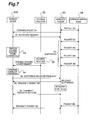
- Fig. 7 is a view showing state transition in the event of a handover of the mobile node 200 shown in the Fig. 5.
- the packet B1 Prior to transmission of the buffering request from the mobile node 200, the packet B1 is transmitted from the correspondent node 54 to the mobile node 200 through the mobility agent 60. In this event, the buffering request is transmitted from the mobile node 200 to the mobility agent 60 (S1).
- This buffering request is transmitted prior to switching an access router to be connected.
- buffering of the packets B2 to B5 addressed to the mobile node 200 in the queue 631a is started (S2).
- a router advertisement (RA) from the switched access router 36 is received by the mobile node 200.
- RA a care-of address
- the buffering release request is transmitted from the mobile node 200 to the mobility agent 60 (S5). Buffering is released when the buffering release request is received by the mobility agent 60. However, all the packets B2 to B5 buffered in the queue 631a at the point are not necessarily transmitted continuously to the mobile node 200 at equal intervals.
- the front packet B2 among the four packets B2 to B5 buffered in the queue 631a is firstly transmitted to the mobile node 200 (S6). Then, after 15 ms have passed, the remaining packets B3 to B5 are continuously transmitted to the mobile node 200 by the mobility agent 60 (S7).
- the packet communication system of the second embodiment is, as hitherto described, an example of adopting the mobility agent 60 as the packet transmission control device according to the present invention.
- the mobility agent 60 performs buffering of the packets in the queues individually provided for each of the addresses of the mobile nodes, i.e., the destinations of the packets. Along with the release of buffering, the mobility agent 60 transmits only one front packet among the packets buffered in each queue to the desired mobile node 200. Then, after a lapse of a given time period (such as 15 ms), the mobility agent 60 transmits the remaining packets continuously.
- a given time period such as 15 ms
- the one front packet reaches the correspondent node of the destination while facilitating the resolution of the MAC address by the router, which has an unresolved MAC address, existing on the transmission pathway.
- the remaining packets are routed on the same pathway as that for the front packet.
- a router having an unresolved MAC address no longer exists on that pathway. Therefore, the remaining packets will neither be replaced by subsequent packets nor discarded.
- packet losses are reduced and the plurality of packets certainly reach the destination.
- a rate of retransmission of the packets is reduced, and the network resources can be more efficiently utilized.
- control technique for packet transmission according to the present invention is applied to the mobile node and the mobility agent.
- control technique is also applicable to other communication apparatuses such as a router for transmitting a plurality of packets to a desired destination node.
- control technique for packet transmission in the event of the release of buffering.
- control technique is also applicable to the case where the application requires packet transmission at a shorter transmission interval.
- the mobile node may be any information equipment having a wireless communication function, such as a personal digital assistance (PDA).
- PDA personal digital assistance
- the recording medium is designed to impart a state of energy changes in magnetism, light, electricity or the like, to a reading apparatus provided on hardware resources such as a general-purpose computer, in response to the contents of description of the program.
- the recording medium is designed to be capable of transmitting the contents of description of the program to the reading apparatus in the form of signals corresponding to the energy changes.
- This type of recording medium may be one detachably fitted to a computer (including a mobile terminal), for example: an IC card such as a user identification module (UIM) ; a magnetic disk; an optical disk; or a magneto-optical disk.
- the recording medium may be a nonvolatile semiconductor memory such as a hard disk (HD) fixedly built in the computer or integrally fixed firmware.
- HD hard disk
- the above program may have a constitution in which communicating means provided in a wireless control apparatus according to the present invention receives and records the program either partially or entirely, from another instrument, through a transmission medium such as a communication line.
- the above program may have a constitution in which the program is transmitted from the wireless control apparatus according to the present invention through the transmission medium, to another instrument to be installed.
Abstract
Description
- The present invention relates to a packet transmission control apparatus, a mobile node, a control node, a packet communication method, and a packet communication system.
- Conventionally, a packet communication has been put into practical use in which a packet is transmitted from a source node to a destination node through a plurality of routers. Among the plurality of routers existing on a pathway between the nodes, there may be a router having an unresolved media access control (MAC) address of a router to which the packet addressed to the destination node is to be routed (forwarded).
- The router having the unresolved MAC address is a router among the routers through which a packet passes when transmitted to the destination node, and this router does not hold a MAC address of a successive routing destination of the packet.
- The router having the unresolved MAC address for the successive routing destination (which will be tentatively referred to as the "router A") needs to recognize the MAC address of the router which corresponds to the successive routing destination (which will be tentatively referred to as the "router B") by the use of an address resolution protocol (ARP). In this event, the router A broadcasts an ARP request packet having an internet protocol (IP) address of the router B to a link to which the router B is connected. The broadcasted ARP request packet is received by all nodes on the link, and the contents of the ARP request packet are analyzed. Of the nodes on the link, the router B confirms that the router B itself is the object of the ARP request, and transmits to the router A an ARP response packet having the MAC address of the router B. Upon receipt of this ARP response, the router A obtains the MAC address of the router B.
- The above-described operations by the router A will be referred to as the "MAC address resolution". Meanwhile, a "time period necessary for resolving the MAC address" is a time period consumed from the time point at which the ARP request packet is transmitted by the router A until the router A receives and analyzes the ARP response packet and then obtains the MAC address of the router B.
- If a plurality of packets addressed to the same transmittee reach the router having the unresolved MAC address at an interval within the time period necessary for resolving the MAC address (which is normally several milliseconds), then there is a concern regarding the following problem.
- Specifically, if the plurality of packets reach the router highly frequently before the router resolves the MAC address upon receipt of the packets addressed to a destination host, the respective packets are replaced by the subsequent packets because a buffering area is limited. As a result, the packets except the one that reach the router last may be discarded. Discard of the packets like this may result in an occurrence of a packet receiving failure by the destination host (a packet loss).
- The present invention has been made in consideration of the foregoing problem. It is an object of the present invention to provide a packet transmission control apparatus, a mobile node, a control node, a packet communication method, and a packet communication system, which are capable of certainly delivering a plurality of packets to a destination.
- To address the problem explained earlier, a packet transmission control apparatus according to the present invention is a packet transmission control apparatus which sequentially transmits a plurality of packets addressed to a destination node (including various routers) at an interval within a first time period. Here, the packet transmission control apparatus includes: packet accumulating means for buffering (temporarily retaining) the plurality of packets; and packet transmission controlling means for transmitting to the destination node a front packet included in the plurality of packets buffered in the packet accumulating means and for transmitting the remaining packet (a packet or packets other than the front packet) included in the plurality of packets to the destination node after the lapse of a second time period starting from a time point when the front packet was transmitted.
- Apacket communication method according to the present invention is a packet communication method for allowing a packet transmission control apparatus to sequentially transmit a plurality of packets addressed to a destination node at an interval within a first time period. Here, the method includes: a front packet transmitting step which allows the packet transmission control apparatus to transmit, to the destination node, a front packet included in the plurality of packets buffered in packet accumulating means; and a subsequent packet transmitting step which allows the packet transmission control apparatus to transmit the remaining packet included in the plurality of packets to the destination node after the lapse of a second time period starting from a time point when the front packet was transmitted in the front packet transmitting step.
- According to these aspects of the invention, when it is assumed that the plurality of packets addressed to the destination node are sequentially transmitted at the interval within the first time period, the front packet included in the buffered plurality of packets is firstly transmitted to the destination node, and the remaining packet is transmitted to the destination node after the lapse of the second time period starting from the time point when the front packet was transmitted.
- In this way, it is possible to suppress buffering of plenty of packets by the node which receives the front packet addressed to the destination node before the node resolves the MAC address. In other words, the remaining packet is received by the node after resolution processing of the MAC address based on the front packet is completed. Therefore, the respective packets are not replaced by the subsequent packets or discarded instead thereof. As a result, packet losses are reduced and the packet transmission control apparatus can certainly deliver the plurality of packets to the transmittee.
- In the packet transmission control apparatus according to the present invention, it is preferable that the first time period is a time period necessary for a node for relaying the packet transmitted by the packet transmission control apparatus, to resolve a MAC address of a routing destination of the packet.
- In the packet communication method according to the present invention, it is preferable that the first time period is a time period necessary for a node for relaying the packet transmitted by the packet transmission control apparatus, to resolve a MAC address of a routing destination of the packet.
- The first time period is equivalent to the time period necessary for the node for relaying the packet transmitted by the packet transmission control apparatus, to resolve the MAC address of the routing destination of the packet (such a time period will be referred to as the "address resolution time period"). For example, the first time period is equivalent to a time period necessary for an apparatus, which is connected directly to the packet transmission control apparatus as a subsequent node, to resolve a MAC address of a successive node that is the routing destination of the packet.
- Replacement of the packet by the subsequent packet constitutes an impediment to certain transmission of the packet which is the object of the present invention. Occurrence of such replacement is attributable to an aspect that the subsequent packet catches up with the precedent packet while the MAC address of the routing destination of the precedent packet is unresolved. Here, the subsequent packet catches up with the precedent packet in the case when a transmission interval of the respective packets is shorter than the above-described address resolution time period. Accordingly, by adopting the packet transmission control technique of the present invention only to the above-described case, it is possible to achieve efficient packet transmission while reducing redundant time elapse associated with standby for transmission of the subsequent packet.
- In the packet transmission control apparatus according to the present invention, it is more preferable that the second time period is a time period that all the nodes which are to resolve the MAC address require to resolve the Mac address. These nodes are among the nodes which the plurality of packets transmitted from the packet transmission control apparatus pass through before reaching the destination node.
- In the packet communication method according to the present invention, it is more preferable that the second time period is a time period that all the nodes which are to resolve the MAC address require to resolve the MAC address. These nodes are among the nodes which the plurality of packets transmitted from the packet transmission control apparatus pass through before reaching the destination node.
- According to these aspects of the invention, the second time period is the time period that all the nodes which are to resolve the MAC address require to resolve the MAC address. These nodes are among the nodes which the plurality of packets transmitted from the packet transmission control apparatus pass through before reaching the destination node. In this way, by the time point at which the remaining packet is transmitted from the packet transmission control apparatus, all the nodes which are to resolve the MAC address and through which the remaining packet passes before reaching the destination node will have completed the resolution processing of the MAC address. The front packet and the remaining packet trace the same pathway to reach the targeted node. However, in this event, the remaining packet never catches up with the front packet. Therefore, certainty of transmitting the plurality of packets to a desired destination is enhanced.
- It is also possible to construct and utilize a packet communication system which includes the above-described packet transmission control apparatus, and the destination node for receiving the plurality of packets transmitted from the packet transmission control apparatus.
- A mobile node (for example, a mobile station such as a mobile telephone) according to the present invention is a mobile node including a link layer for switching an access router to be connected, and an internet protocol (IP) layer for controlling to transmit a plurality of packets sequentially to a destination node through the access router at an interval within a first time period. Here, the IP layer includes abuffer area in which the plurality of packets are buffered in a disconnection period when the mobile node switches the access router to be connected. Moreover, the IP layer performs control of transmitting a front packet included in the plurality of packets buffered in the buffer area to the switched access router. The IP layer also controls transmission of the remaining packet included in the plurality of packets to the switched access router after a lapse of a second time period starting from a time point when the front packet was transmitted.
- The link layer and the IP layer represent definitions of standard function modules for respective layers resulted from classifying communication functions expected in respective nodes into a layered structure based on a design rule (such as the open systems interconnection (OSI)) for a network structure to achieve communications between different nodes.
- Apacket communication method according to the present invention is a packet communication method for allowing a mobile node to switch an access router to be connected and to sequentially transmit a plurality of packets to a destination node through the access router at an interval within a first time period. Here, the method includes: a front packet transmitting step of transmitting, to a switched access router, a front packet included in the plurality of packets buffered in packet accumulating means in a disconnection period when the mobile node switches the access router to be connected; and a subsequent packet transmitting step of allowing the mobile node to transmit the remaining packet included in the plurality of packets to the switched access router after a lapse of a second time period starting from a time point when the front packet was transmitted in the front packet transmitting step.
- The mobile node buffers the packet to be transmitted to the access router into the buffer area in the disconnection period during a handover for switching the access router to be connected. These aspects of the invention is based on the assumption that the mobile node sequentially transmits the plurality of packets addressed to the destination node through the access router at the interval within the first time period. According to these aspects of the invention, the front packet included in the plurality of packets buffered by the mobile node is firstly transmitted to the switched access router. After a lapse of the second time period starting from the time point when the front packet was transmitted, the remaining packet is transmitted to the switched access router.
- In this way, it is possible to suppress buffering of plenty of packets by the switched access router, which has received the front packet addressed to the destination node, beyond the processing capability of the access router for resolving the MAC address. In other words, the remaining packet is received by the access router after resolution processing of the MAC address based on the front packet is completed. Therefore, the respective packets are not replaced by the subsequent packets or discarded. As a result, packet losses are reduced and the mobile node can certainly deliver the plurality of packets to the destination.
- In the mobile node according to the present invention, it is preferable that the first time period is a time period necessary for any of the switched access router and a node for relaying the packet transmitted by the mobile node, to resolve a MAC address of a routing destination of the packet.
- In the packet communication method according to the present invention, it is preferable that the first time period is a time period necessary for any of the switched access router and a node for relaying the packet transmitted by the mobile node, to resolve a MAC address of a routing destination of the packet.
- The first time period is equivalent to the address resolution time period by the switched access router, concerning the routing destination of the packet. For example, the first time period is equivalent to the time period necessary for either the switched access router, which is connected directly to the mobile node as a subsequent node, or a node that relays the packet transmitted by the mobile node, to resolve a MAC address of a successive node which is the routing destination of the packet.
- Replacement of the packet by the subsequent packet constitutes an impediment to certain transmission of the packet which is the object of the present invention. Occurrence of such replacement is attributable to an aspect that the subsequent packet catches up with the precedent packet while the MAC address of the routing destination of the precedent packet is unresolved. Here, the subsequent packet catches up with the precedent packet in the case when a transmission interval of the respective packets is shorter than the address resolution time period described earlier. Accordingly, by adopting the packet transmission control technique of the present invention only to the above-described case, it is possible to achieve efficient packet transmission while reducing redundant time elapse associated with standby for transmission of the subsequent packet.
- In the mobile node according to the present invention, it is more preferable that the second time period is a time period that all the nodes which are to resolve the MAC address require to resolve the MAC address. These nodes are among the nodes which the plurality of packets transmitted from the mobile node pass through before reaching the destination node.
- In the packet communication method according to the present invention, it is more preferable that the second time period is a time period that all the nodes which are to resolve the MAC address require to resolve the MAC address . These nodes are among the nodes which the plurality of packets transmitted from the mobile node pass through before reaching the destination node.
- According to these aspects of the invention, the second time period is the time period that all the nodes (including the switched access router) which are to resolve the MAC address require to resolve the MAC address. These nodes are among the nodes which the plurality of packets transmitted from the mobile node pass through before reaching the destination node. In this way, by the time point at which the remaining packet are transmitted from the mobile node, all the nodes which are to resolve the MAC address and through which the remaining packet passes before reaching the destination node will have completed the resolution processing of the MAC address. The front packet and the remaining packet trace the same pathway to reach the targeted node. However, in this event, the remaining packet never catches up with the front packet. Therefore, the mobile node can deliver the plurality of packets to a desired transmittee more certainly.
- It is also possible to construct and utilize a packet communication system which includes the above-described mobile node, and the destination node for receiving the plurality of packets transmitted from the mobile node through the access router.
- A control node according to the present invention is a control node including an internet protocol (IP) layer for controlling for sequentially transmitting a plurality of packets to a mobile node through a router at an interval within a first time period. Here, the IP layer includes a buffer area in which the plurality of packets are buffered in response to a buffering request from the mobile node. The IP layer controls transmission of a front packet included in the plurality of packets buffered in the buffer area, to the mobile node in response to a buffering release request from the mobile node. The IP layer also controls transmission of the remaining packet included in the plurality of packets, to the mobile node after a lapse of a second time period starting from a time point of transmission of the front packet.
- Apacket communication method according to the present invention is a packet communication method for allowing a control node to sequentially transmit a plurality of packets to amobile node that switches an access router to be connected thereto, though a router at an interval within a first time period. Here, the method includes: a front packet transmitting step which allows the control node to transmit, to the mobile node, a front packet included in the plurality of packets buffered in packet accumulating means in response to a buffering request from the mobile node, upon receipt of a buffering release request from the mobile node; and a subsequent packet transmitting step which allows the control node to transmit the remaining packet included in the plurality of packets to the mobile node after a lapse of a second time period starting from a time point when the front packet was transmitted in the front packet transmitting step.
- The control node (such as a mobility agent that is connected to a regional mobile network comprising a plurality of routers) buffers the packet tobe transmitted to the mobile node into the buffer area, in response to the buffering request transmitted due to a handover which allows the mobile node to switch the access router to be connected thereto. These aspects of the invention is based on an assumption that the control node sequentially transmits the plurality of packets addressed to the mobile node through the router, at the interval within the first time period. According to these aspects of the invention, the front packet included in the plurality of packets buffered by the control node is firstly transmitted to the mobile node. After a lapse of the second time period starting from the time point at which the front packet was transmitted, the remaining packet is transmitted to the mobile node.
- In this way, it is possible to suppress buffering of plenty of packets in the router, which receives the front packet addressed to the mobile node, beyond a processing capability of the router for resolving the MAC address. In other words, the remaining packet is received by the router after resolution processing of the MAC address based on the front packet is completed. Therefore, the respective packets are not replaced by the subsequent packets or discarded. As a result, packet losses are reduced and the control node can certainly deliver the plurality of packets to the destination.
- In the control node according to the present invention, it is preferable that the first time period is a time period necessary for a node (including the router), which relays the packet transmitted by the control node, to resolve a MAC address of a routing destination of the packet.
- In the packet communication method according to the present invention, it is preferable that the first time period is a time period necessary for a node, which relays the packet transmitted by the control node, to resolve a MAC address of a routing destination of the packet.
- The first time period is equivalent to the address resolution time period by the router concerning the routing destination of the packet. For example, the first time period is equivalent to the time period necessary for a router, which is connected directly to the control node as a node subsequent to the control node, to resolve a MAC address of a successive node that is the routing destination of the packet.
- Replacement of the packet by the subsequent packet constitutes an impediment to certain transmission of the packet which is the object of the present invention. Occurrence of such replacement is attributable to an aspect that the subsequent packet catches up with the precedent packet while the MAC address of the routing destination of the precedent packet is unresolved. Here, the subsequent packet catches up with the precedent packet in the case when a transmission interval of the respective packets is shorter than the address resolution time period described earlier. Accordingly, by adopting the packet transmission control technique of the present invention only to the above-described case, it is possible to achieve efficient packet transmission while reducing redundant time elapse associated with standby for transmission of the subsequent packet.
- In the control node according to the present invention, it is more preferable that the second time period is a time period that all the nodes which are to resolve the MAC address require to resolve the MAC address. These nodes are among the nodes which the plurality of packets transmitted from the control node pass through before reaching the mobile node.
- In the packet communication method according to the present invention, it is more preferable that the second time period is a time period that all the nodes (including the switched access router) which are to resolve the MAC address require to resolve the MAC address. These nodes are among the nodes which the plurality of packets transmitted from the control node pass through before reaching the mobile node.
- According to these aspects of the invention, the second time period is the time period that all the nodes (including the relay router and the access router) which are to resolve the MAC address require to resolve MAC address . These nodes are among the nodes which the plurality of packets transmitted from the control node pass through before reaching the mobile node. In this way, at the time point at which the remaining packet is transmitted from the control node, all the nodes which are to resolve the MAC address and through which the remaining packet passes before reaching the mobile node will have completed the resolution processing of the MAC address. The front packet and the remaining packet trace the same pathway to reach the targeted node. However, in this event, the remaining packet never catches up with the front packet. Therefore, certainty of transmitting the plurality of packets from the mobile node to a desired destination is enhanced.
- It is also possible to construct and utilize a packet communication system which includes the above-described control node, and the mobile node for receiving the plurality of packets transmitted from the control node through the router.
- The present invention will become more fully understood from the detailed description given herein below and the accompanying drawings which are given by way of illustration only, and thus are not to be considered as limiting the present invention.
- Further scope of applicability of the present invention will become apparent from the detailed description given hereinafter. However, it should be understood that the detailed description and specific examples, while indicating preferred embodiments of the invention, are given by way of illustration only, since various changes and modifications within the spirit and scope of the invention will become apparent to those skilled in the art from this detailed description.
-
- Fig. 1 is a block diagram showing an overall configuration of a packet communication system according to a first embodiment.
- Fig. 2 is a conceptual view for explaining a functional constitution and operations of a mobile node according to the first embodiment.
- Fig. 3 is a view showing state transition in the event of a handover of the mobile node in the first embodiment.
- Fig. 4 is a table showing correlation between a connection point of a link layer and a default router in different states, respectively.
- Fig. 5 is a block diagram showing an overall configuration of a packet communication system according to a second embodiment.
- Fig. 6 is a conceptual view for explaining a functional constitution and operations of a mobility agent according to the second embodiment.
- Fig. 7 is a view showing state transition in the event of a handover of a mobile node in the second embodiment.
-
- A first embodiment of the present invention is described in detail below with reference to the accompanying drawings.
- As a premise of description, this embodiment is based on an assumption of the case where the packet transmission control technique according to the present invention is adopted to a mobile node. Fig. 1 is a block diagram showing an overall configuration of a packet communication system according to the first embodiment of the present invention. Apacket communication system 1 shown in Fig. 1 is configured by including amobile node (MN) 100 such as amobile telephone, a regional mobile network N2, a known backbone network N1, and a plurality of correspondent nodes (CN) 51, 52 and 53.
- Here, this packet communication system is constructed in accordance with the modes including the regional registrations, the hierarchical mobile IP, and the like, which are proposed by the Internet Engineering Task Force (IETF).
- The regional mobile network N2 is constituted by wire connection of access routers (AR) 31, 32, and 33 severally provided in a plurality of
base stations relay routers 41 to 46 connected directly or indirectly to theseaccess routers 31 to 33. Moreover, the regional mobile network N2 is connected to thecorrespondent nodes 51 to 53 by wires through the backbone network N1. - The mobile node 100 (corresponding to a packet transmission control apparatus) is wirelessly connected to anyone of the
access routers 31 to 33 depending on the location ofmobile node 100, and is handed over among the access routers while transmitting packets to the plurality ofcorrespondent nodes access routers 31 to 33 and therelay routers 41 to 46 (hereinafter collectively referred to as the "routers") execute resolution processing of a media access control (MAC) address in order to specify a router as a subsequent routing destination of the packets. Here, for each of the relay routers and the access routers through which the packets pass after being transmitted until received, a time period required to resolve the MAC address of the node, which is the subsequent routing destination of the packets, is preferably set to about 5 ms (corresponding to a first time period). - The packets which are transmitted from the
mobile node 100 to any one of thecorrespondent nodes 51 to 53 are routed to the backbone network N1 through one of the access routers connected to the mobile node when the packets are transmitted and two of the relay routers. In this event, if there is no router having an unresolved MAC address after the backbone network N1, then the packets are routed through up to three routers having unresolved MAC addresses before reaching a desired destination node. Therefore, as a transmission standby time period (corresponding to a second time period) , 5 ms × 3 = 15 ms is preferably preset on themobile node 100. - Fig . 2 is a conceptual view for explaining a functional constitution and operations of the mobile node.
- As shown in fig. 2, the
mobile node 100 includes an application 11 in anapplication layer 11a, a transmission control protocol (TCP)/user datagram protocol (UDP) 12 in atransport layer 12a, a internet protocol (IP) (corresponding to packet transmission controlling means) 13 having a buffer area 131 (corresponding to packet accumulating means) in an internet protocol (IP)layer 13a, alink 14 and aninterface 15 in alink layer 14a. - Data transmitted from the application 11 to another node is transmitted sequentially through the TCP/
UDP 12, theIP 13, thelink 14, and theinterface 15. Meanwhile, data transmitted from the other node to the application 11 is received sequentially through theinterface 15, thelink 14, theIP 13, and the TCP/UDP 12. - When a connection point is switched from the
access router 32 to theaccess router 33, a buffering request is outputted from theinterface 15 to theIP 13. When the buffering request is inputted to theIP 13, the packets are buffered in thebuffer area 131. To be more precise, the packet is buffered inqueues 131a to 131d which constitute a data retention area prepared for respective destination addresses of the packets. - The
IP 13 releases buffering at a time point when a default router is changed by a router advertisement (RA) received from theaccess router 33. When buffering is released, theIP 13 hands over, to thelink layer 14a, only one front packet (such as a packet A1 in thequeue 131a) out of the packets buffered in each queue. Then, after 15 ms have passed, theIP 13 hands over the remaining packets retained in each queue to thelink layer 14a. - Fig. 3 is a view showing state transition in the event of a handover of the
mobile node 100 shown in Fig. 1. The state transition associated with the handover of themobile node 100 is categorized into four states (states I to IV) as shown in fig. 3. Meanwhile, Fig. 4 is a table showing correlation between the connection point of thelink layer 14a and the default router in each of the states. - The state I is a state where the
link layer 14a of themobile node 100 is connected to theaccess router 32, and the default router is theaccess router 32. The state II is a state where thelink layer 14a of themobile node 100 is being switched from theaccess router 32 to the access router 33 (in a link layer outage time period) and the default router is still theaccess router 32. - The state III is a state where the
link layer 14a of themobile node 100 is connected to theaccess router 33 and theaccess router 32 remains the default router. The state III is continued until themobile node 100 receives the RA of theaccess router 33 and thereby changes the default router from theaccess router 32 to theaccess router 33. The state IV is a state after themobile node 100 received the RA of theaccess router 33 and thereby changed the default router from theaccess router 32 to theaccess router 33. In this event, each of the connection point of thelink layer 14a and the default router is theaccess router 33. - When the connection point of the
link layer 14a and the default router coincide with each other (in the state I and the state IV), the packets transmitted from themobile node 100 addressed to thecorrespondent node 51 that is the destination thereof are receivedby the corresponding access router (that is, theaccess router 32 in the state I or theaccess router 33 in the state IV). Thereafter, the received packets are routed to thecorrespondent node 51. - On the contrary, when the connection point of the
link layer 14 and the default router do not coincide with each other (in the state II and the state III), the packets transmitted from themobile node 100 toward thecorrespondent node 51 that is the destination thereof are buffered in thequeue 131a and then transmitted to the destination node after transition to the state IV (after the default router is changed). - As described above, according to the packet communication system 1 of the first embodiment, the
mobile node 100 performs buffering of the packets into therespective queues correspondent nodes mobile node 100 first transmits only one front packet out of the packets buffered in each queue to the desired correspondent node. Then, after a lapse of a given time period (such as 15 ms), themobile node 100 transmits the remaining packets continuously. - In this way, the front packet reaches the correspondent node of the destination while facilitating the resolution of the MAC address by the router, which has an unresolved MAC address, existing on the transmission pathway. After a lapse of the given time period, the remaining packets are routed through the same pathway as that for the front packet. However, a router having an unresolved MAC address no longer exists on that pathway. Therefore, the remaining packets willbeneitherreplacedbysubsequentpacketsnordiscarded. As a result, packet losses are reduced and the plurality of packets certainly reach the destination. In addition, a rate of retransmission of the packets is reduced, and the network resources can be more efficiently utilized.
- Next, a second embodiment of the present invention is described in detail with reference to the accompanying drawings.
- As a premise of description, this embodiment is based on an assumption of the case where the packet transmission control technique according to the present invention is adopted to a mobility agent (MA).
- Fig. 5 is a block diagram showing an overall configuration of a packet communication system according to this embodiment. A packet communication system 2 shown in Fig. 5 is configured by including a mobile node (MN) 200 such as a mobile telephone, a regional mobile network N2, a known backbone network N1, and one correspondent node (CN) 54.
- The regional mobile network N2 is constituted by wire connection of access routers (AR) 34, 35, and 36 respectively provided in a plurality of
base stations relay routers 47 to 49 connected directly to theseaccess routers 34 to 36, and onemobility agent 60. Moreover, the regional mobile network N2 is connected to thecorrespondent node 54 by wire through the backbone network N1. - The
mobile node 200 is wirelessly connected to any one of theaccess routers 34 to 36 depending on the location ofmobile node 200, and is handed over between theaccess routers correspondent node 54. - The
access routers 34 to 36 and therelay routers 47 to 49 (hereinafter collectively referred to as the "routers") execute resolution processing of a MAC address in order to specify a router as a subsequent routing destination of the packets. - The
mobility agent 60 is a node which receives the packets transmitted from thecorrespondent node 54 addressed to themobile node 200 and transmits the packets to the access router currently connected to themobile node 200. Here, for each of the relay routers and the access routers through which the packets pass through after transmitted until received, a time period required to resolve the MAC address of the node that is the subsequent routing destination of the packets is preferably set to about 5 ms (corresponding to a first time period). - The packets which are transmitted from an apparatus after the backbone network N1 (such as the correspondent node 54) to the
mobile node 200 currently connected to theaccess router 35 reach themobile node 200 through themobility agent 60, therelay router access router - In this event, if there is no router having an unresolved MAC address after the backbone network N1, then the packets will be routed through up to three routers having unresolved MAC addresses (including the mobility agent 60)before reaching the
mobile node 200. Therefore, as a transmission standby time period (corresponding to a second time period), 5 ms × 3 = 15 ms is preferably preset on themobility agent node 60. - Fig. 6 is a conceptual view for explaining a functional constitution and operations of the mobility agent. As shown in Fig. 6, the
mobility agent 60 includes an IP 63 (corresponding to packet transmission controlling means) having a buffer area 631 (corresponding to packet accumulating means) in anIP layer 63a, andlinks 641 to 644 as well asinterfaces 651 to 654 inlink layers 641a to 644a. The packets received by theIP 63 through thelink layer 644a having thelink 644 connected to the backbone network N1 are sorted to be transmitted to an appropriate link (any one of thelinks 641 to 643) in accordance with a routing table (not shown) possessed by theIP 63. - Upon receipt of a buffering request transmitted from the
mobile node 200 through any of thelinks 641 to 643, theIP 63 buffers the packets addressed to themobile node 200 in a corresponding queue (aqueue 631a in this case) within the buffer area. Such buffering is continued until theIP 63 receives a buffering release request which is transmitted from themobile node 200 through any one of thelinks 641 to 643. - Along with receipt of the buffering release request, the
IP 63 hands over only one front packet (a packet B2) retained in thequeue 631a to theappropriate link layer 643a in accordance with the routing table described earlier. Then, after a standby for 15 ms, theIP 63 hands over the remaining packets (packets B3 to B5 except the front packet) retained in thequeue 631a to theappropriate link layer 643a. - Fig. 7 is a view showing state transition in the event of a handover of the
mobile node 200 shown in the Fig. 5. Prior to transmission of the buffering request from themobile node 200, the packet B1 is transmitted from thecorrespondent node 54 to themobile node 200 through themobility agent 60. In this event, the buffering request is transmitted from themobile node 200 to the mobility agent 60 (S1). - This buffering request is transmitted prior to switching an access router to be connected. When the buffering request is transmitted by the
mobile node 200, buffering of the packets B2 to B5 addressed to themobile node 200 in thequeue 631a is started (S2). - When the access router to be connected is switched by the mobile node 200 (S3), a router advertisement (RA) from the switched
access router 36 is received by themobile node 200. Upon receipt of the RA, a care-of address is changed (S4). - When switching the access router to be connected is completed, the buffering release request is transmitted from the
mobile node 200 to the mobility agent 60 (S5). Buffering is released when the buffering release request is received by themobility agent 60. However, all the packets B2 to B5 buffered in thequeue 631a at the point are not necessarily transmitted continuously to themobile node 200 at equal intervals. - That is to say, when receipt of the buffering release request is detected, the front packet B2 among the four packets B2 to B5 buffered in the
queue 631a is firstly transmitted to the mobile node 200 (S6). Then, after 15 ms have passed, the remaining packets B3 to B5 are continuously transmitted to themobile node 200 by the mobility agent 60 (S7). - Note that this embodiment has been typically described regarding transmission control of the packets retained in the
queue 631a that are addressed to themobile node 200. However, regarding packets addressed to other mobile nodes (not shown) to be retained in thequeues 631b to 631d apart from thequeue 631a, similar processing is also performed in each of the queues and the mobile nodes. - The packet communication system of the second embodiment is, as hitherto described, an example of adopting the
mobility agent 60 as the packet transmission control device according to the present invention. Themobility agent 60 performs buffering of the packets in the queues individually provided for each of the addresses of the mobile nodes, i.e., the destinations of the packets. Along with the release of buffering, themobility agent 60 transmits only one front packet among the packets buffered in each queue to the desiredmobile node 200. Then, after a lapse of a given time period (such as 15 ms), themobility agent 60 transmits the remaining packets continuously. - In this way, the one front packet reaches the correspondent node of the destination while facilitating the resolution of the MAC address by the router, which has an unresolved MAC address, existing on the transmission pathway. After a lapse of the given time period, the remaining packets are routed on the same pathway as that for the front packet. However, a router having an unresolved MAC address no longer exists on that pathway. Therefore, the remaining packets will neither be replaced by subsequent packets nor discarded. As a result, packet losses are reduced and the plurality of packets certainly reach the destination. In addition, a rate of retransmission of the packets is reduced, and the network resources can be more efficiently utilized.
- It is to be noted that the aspects described in the respective embodiments are preferred examples of the packet communication system according to the present invention. Accordingly, the present invention is not limited to the aspects described herein.
- For example, in the each of the foregoing embodiments, descriptions have been made regarding the examples in which the control technique for packet transmission according to the present invention is applied to the mobile node and the mobility agent. However, without limiting to these nodes, the above control technique is also applicable to other communication apparatuses such as a router for transmitting a plurality of packets to a desired destination node.
- Moreover, in each of the foregoing embodiments, a description has been made regarding the control technique for packet transmission in the event of the release of buffering. However, the above-described control technique is also applicable to the case where the application requires packet transmission at a shorter transmission interval.
- Furthermore, in each of the foregoing embodiments, descriptions have been made based on the assumption that the mobile node is a mobile telephone. However, the mobile node may be any information equipment having a wireless communication function, such as a personal digital assistance (PDA).
- Lastly, a description is provided concerning a program for achieving the packet transmission control technique according to the present invention, and a computer-readable recording medium which records the program (hereinafter simply referred to as the "recording medium"). The recording medium is designed to impart a state of energy changes in magnetism, light, electricity or the like, to a reading apparatus provided on hardware resources such as a general-purpose computer, in response to the contents of description of the program. Moreover, the recording medium is designed to be capable of transmitting the contents of description of the program to the reading apparatus in the form of signals corresponding to the energy changes. This type of recording medium may be one detachably fitted to a computer (including a mobile terminal), for example: an IC card such as a user identification module (UIM) ; a magnetic disk; an optical disk; or a magneto-optical disk. In addition, the recording medium may be a nonvolatile semiconductor memory such as a hard disk (HD) fixedly built in the computer or integrally fixed firmware.
- Moreover, the above program may have a constitution in which communicating means provided in a wireless control apparatus according to the present invention receives and records the program either partially or entirely, from another instrument, through a transmission medium such as a communication line. On the contrary, the above program may have a constitution in which the program is transmitted from the wireless control apparatus according to the present invention through the transmission medium, to another instrument to be installed.
- From the invention thus described, it will be obvious that the embodiments of the invention may be varied in many ways. Such variations are not to be regarded as a departure from the spirit and scope of the invention, and all such modifications as would be obvious to one skilled in the art are intended for inclusion within the scope of the following claims.
Claims (15)
- A packet transmission control apparatus which sequentially transmits a plurality of packets addressed to a destination node at an interval within a first time period, the packet transmission control apparatus comprising:packet accumulating means for buffering the plurality of packets; andpacket transmission controlling means for transmitting, to the destination node, a front packet included in the plurality of packets buffered in the packet accumulating means and for transmitting the remaining packet included in the plurality of packets to the destination node after a lapse of a second time period starting from a time point of transmission of the front packet.
- The packet transmission control apparatus according to claim 1,
wherein the first time period is a time period necessary for a node to resolve a MAC address of a routing destination of the packet, the node relaying the packet transmitted by the packet transmission control apparatus. - The packet transmission control apparatus according to claim 1,
wherein the second time period is a time period necessary for all nodes, which are to resolve the MAC address, to resolve the MAC address, the nodes being among nodes which the plurality of packets transmitted from the packet transmission control apparatus pass through before reaching the destination node. - A mobile node comprising:wherein the IP layer includes a buffer area in which the plurality of packets are buffered in a disconnection period when the mobile node switches the access router to be connected, anda link layer for switching an access router to be connected; andan IP layer for controlling for sequential transmission of a plurality of packets to a destination node through the access router at an interval within a first time period,
the IP layer performs control of transmitting a front packet included in the plurality of packets buffered in the buffer area to the switched access router, and of transmitting the remaining packet included in the plurality of packets to the switched access router after a lapse of a second time period starting from a time point of transmission of the front packet. - The mobile node according to claim 4,
wherein the first time period is a time period necessary for any of the switched access router and a node for relaying the packet transmitted by the mobile node, to resolve a MAC address of a routing destination of the packet. - The mobile node according to claim 4,
wherein the second time period is a time period necessary for all nodes which are to resolve the MAC address to resolve the MAC address, the nodes being among nodes which the plurality of packets transmitted from the mobile node pass through before reaching the destination node. - A control node comprising:wherein the IP layer includes a buffer area in which the plurality of packets are buffered in response to a buffering request from the mobile node, andan IP layer for controlling sequential transmission of a plurality of packets to a mobile node through a router at an interval within a first time period,
the IP layer performs control of transmission of a front packet included in the plurality of packets buffered in the buffer area to the mobile node in response to a buffering release request from the mobile node, and of transmission of the remaining packet included in the plurality of packets to the mobile node after a lapse of a second time period starting from a time point of transmission of the front packet. - The control node according to claim 7,
wherein the first time period is a time period necessary for a node to resolve a media MAC address of a routing destination of the packet, the node relaying the packet transmitted by the control node. - The control node according to claim 7,
wherein the second time period is a time period necessary for all nodes, which are to resolve the MAC address, to resolve the MAC address, the nodes being among nodes which the plurality of packets transmitted from the control node pass through before reaching the mobile node. - A packet communication method for allowing a packet transmission control apparatus to sequentially transmit a plurality of packets addressed to a destination node at an interval within a first time period, the method comprising:a front packet transmitting step of allowing the packet transmission control apparatus to transmit, to the destination node, a front packet included in the plurality of packets buffered in packet accumulating means; anda subsequent packet transmitting step of allowing the packet transmission control apparatus to transmit the remaining packet included in the plurality of packets to the destination node after a lapse of a second time period starting from a time point of transmission of the front packet in the front packet transmitting step.
- A packet communication method for allowing a mobile node to switch an access router to be connected and to sequentially transmit a plurality of packets to a destination node through the access router at an interval within a first time period, the method comprising:a front packet transmitting step of transmitting, to a switched access router, a front packet included in the plurality of packets buffered in packet accumulating means during a disconnection period when the mobile node switches the access router to be connected thereto; anda subsequent packet transmitting step of allowing the mobile node to transmit the remaining packet included in the plurality of packets to the switched access router after a lapse of a second time period starting from a time point of transmission of the front packet in the front packet transmitting step.
- A packet communication method for allowing a control node to sequentially transmit a plurality of packets to a mobile node which switches an access router to be connected thereto though a router at an interval within a first time period, the method comprising:a front packet transmitting step of allowing the control node to transmit, to the mobile node, a front packet included in the plurality of packets buffered in packet accumulating means in response to a buffering request from the mobile node, the front packet being transmitted in response to a buffering release request from the mobile node; anda subsequent packet transmitting step of allowing the control node to transmit the remaining packet included in the plurality of packets to the mobile node after a lapse of a second time period starting from a time point of transmission of the front packet in the front packet transmitting step.
- A packet communication system comprising:the packet transmission control apparatus according to claim 1; anda destinationnode for receiving a plurality of packets transmitted from the packet transmission control apparatus.
- A packet communication system comprising:the mobile node according to claim 4; anda destination node for receiving aplurality of packets transmitted from the mobile node through an access router.
- A packet communication system comprising:the control node according to claim 7; anda mobile node for receiving a plurality of packets transmitted from the control node through a router.
Applications Claiming Priority (2)
| Application Number | Priority Date | Filing Date | Title |
|---|---|---|---|
| JP2002130947 | 2002-05-02 | ||
| JP2002130947A JP3947424B2 (en) | 2002-05-02 | 2002-05-02 | Packet transmission control device, mobile node, control node, packet communication method, and packet communication system |
Publications (3)
| Publication Number | Publication Date |
|---|---|
| EP1359726A2 true EP1359726A2 (en) | 2003-11-05 |
| EP1359726A3 EP1359726A3 (en) | 2006-01-11 |
| EP1359726B1 EP1359726B1 (en) | 2007-06-13 |
Family
ID=29208243
Family Applications (1)
| Application Number | Title | Priority Date | Filing Date |
|---|---|---|---|
| EP20030009963 Expired - Fee Related EP1359726B1 (en) | 2002-05-02 | 2003-04-30 | Packet transmission control apparatus, mobile node, control node, packet communication method, and packet communication system |
Country Status (7)
| Country | Link |
|---|---|
| US (1) | US7602718B2 (en) |
| EP (1) | EP1359726B1 (en) |
| JP (1) | JP3947424B2 (en) |
| KR (1) | KR100562187B1 (en) |
| CN (1) | CN100387021C (en) |
| DE (1) | DE60314328T2 (en) |
| SG (4) | SG121768A1 (en) |
Families Citing this family (8)
| Publication number | Priority date | Publication date | Assignee | Title |
|---|---|---|---|---|
| US7913294B1 (en) * | 2003-06-24 | 2011-03-22 | Nvidia Corporation | Network protocol processing for filtering packets |
| US8045566B2 (en) * | 2003-08-01 | 2011-10-25 | Hewlett-Packard Development Company, L.P. | Automated router load balancing |
| US6885969B2 (en) * | 2003-08-26 | 2005-04-26 | Mitsubishi Electric Research Laboratories, Inc. | Location estimation in partially synchronized networks |
| DE102004018200A1 (en) * | 2004-04-15 | 2005-11-10 | Deutsche Thomson-Brandt Gmbh | A method for processing a sequence of data packets in a receiver device and receiver device |
| JP4213100B2 (en) * | 2004-09-17 | 2009-01-21 | 富士通株式会社 | Data transfer system and data transfer method |
| JP4741401B2 (en) * | 2006-04-19 | 2011-08-03 | 日本無線株式会社 | Information transfer device |
| US8898220B2 (en) * | 2010-09-15 | 2014-11-25 | Sap Se | Remote method invocation tunneling over hypertext transfer protocol |
| CN104052528B (en) * | 2014-06-10 | 2016-08-31 | 广州三星通信技术研究有限公司 | The apparatus and method communicated with multiple terminals in Intelligent worn device |
Citations (1)
| Publication number | Priority date | Publication date | Assignee | Title |
|---|---|---|---|---|
| US6307843B1 (en) * | 1997-07-18 | 2001-10-23 | Nec Corporation | Ad hoc network of mobile hosts using link table for identifying wireless links and destination addresses |
Family Cites Families (20)
| Publication number | Priority date | Publication date | Assignee | Title |
|---|---|---|---|---|
| AU625628B2 (en) * | 1989-10-12 | 1992-07-16 | Alcatel N.V. | Device for regulating the throughput of virtual circuits on an asynchronous time-division multiplex transmission channel |
| US5163046A (en) | 1989-11-30 | 1992-11-10 | At&T Bell Laboratories | Dynamic window sizing in a data network |
| JPH04176232A (en) * | 1990-11-09 | 1992-06-23 | Hitachi Ltd | Packet communication system and packet communication equipment |
| US5640599A (en) | 1991-12-30 | 1997-06-17 | Apple Computer, Inc. | Interconnect system initiating data transfer over launch bus at source's clock speed and transfering data over data path at receiver's clock speed |
| US5361261A (en) | 1992-11-02 | 1994-11-01 | National Semiconductor Corporation | Frame-based transmission of data |
| GB2282474B (en) | 1993-09-30 | 1998-02-25 | Intel Corp | Buffer memory management for a computer network node |
| US5457679A (en) * | 1993-12-08 | 1995-10-10 | At&T Corp. | Channel sharing and memory sharing in a packet switching system |
| US5613067A (en) * | 1993-12-30 | 1997-03-18 | International Business Machines Corporation | Method and apparatus for assuring that multiple messages in a multi-node network are assured fair access to an outgoing data stream |
| US5859835A (en) | 1996-04-15 | 1999-01-12 | The Regents Of The University Of California | Traffic scheduling system and method for packet-switched networks |
| JPH104431A (en) | 1996-06-17 | 1998-01-06 | Fujitsu Ltd | Scheduling device and method |
| US5905725A (en) * | 1996-12-16 | 1999-05-18 | Juniper Networks | High speed switching device |
| US5857082A (en) * | 1997-04-25 | 1999-01-05 | Intel Corporation | Method and apparatus for quickly transferring data from a first bus to a second bus |
| US6178174B1 (en) * | 1997-08-26 | 2001-01-23 | International Business Machines Corporation | Optimistic, eager rendezvous transmission mode and combined rendezvous modes for message processing systems |
| US6003088A (en) | 1997-08-29 | 1999-12-14 | International Business Machines Corporation | Blocking IP datagrams in a multi-path channel point-to-point environment |
| JP3413788B2 (en) | 1997-09-25 | 2003-06-09 | 日本電信電話株式会社 | Communication method having communication protocol for performing flow control between layers and data communication terminal |
| DE19927291A1 (en) * | 1999-06-15 | 2000-12-28 | Siemens Ag | Method and device for transmitting data |
| DE19940565C1 (en) * | 1999-08-26 | 2001-02-01 | Siemens Ag | Connection path control for optic data packet transmission |
| US6510144B1 (en) * | 1999-12-07 | 2003-01-21 | Cisco Technology, Inc. | Network layer support to enhance the transport layer performance in mobile and wireless environments |
| US6947401B2 (en) * | 2000-03-08 | 2005-09-20 | Telefonaktiebolaget Lm Ericsson (Publ) | Hierarchical mobility management for wireless networks |
| JP3648470B2 (en) * | 2001-09-18 | 2005-05-18 | 株式会社東芝 | Mobile terminal, router device, node device, mobile agent, packet transfer method, and mobile agent processing method |
-
2002
- 2002-05-02 JP JP2002130947A patent/JP3947424B2/en not_active Expired - Lifetime
-
2003
- 2003-04-30 DE DE2003614328 patent/DE60314328T2/en not_active Expired - Lifetime
- 2003-04-30 EP EP20030009963 patent/EP1359726B1/en not_active Expired - Fee Related
- 2003-05-02 US US10/427,951 patent/US7602718B2/en not_active Expired - Fee Related
- 2003-05-02 SG SG200302482A patent/SG121768A1/en unknown
- 2003-05-02 KR KR20030028234A patent/KR100562187B1/en active IP Right Grant
- 2003-05-02 SG SG200507409-1A patent/SG132537A1/en unknown
- 2003-05-02 SG SG200502895-6A patent/SG135049A1/en unknown
- 2003-05-02 SG SG200507421-6A patent/SG132538A1/en unknown
- 2003-05-06 CN CNB03128521XA patent/CN100387021C/en not_active Expired - Fee Related
Patent Citations (1)
| Publication number | Priority date | Publication date | Assignee | Title |
|---|---|---|---|---|
| US6307843B1 (en) * | 1997-07-18 | 2001-10-23 | Nec Corporation | Ad hoc network of mobile hosts using link table for identifying wireless links and destination addresses |
Non-Patent Citations (4)
| Title |
|---|
| EOM D S ET AL: "PERFORMANCE IMPROVEMENT BY PACKET BUFFERING IN MOBILE IP BASED NETWORKS" IEICE TRANSACTIONS ON COMMUNICATIONS, COMMUNICATIONS SOCIETY, TOKYO, JP, vol. E83-B, no. 11, November 2000 (2000-11), pages 2501-2512, XP001065367 ISSN: 0916-8516 * |
| GOVIND KRISHNAMURTHI NOKIA RESEARCH CENTER ROBERT C CHALMERS UC SANTA BARBARA CHARLES E PERKINS NOKIA RESEARCH CENTER: "Buffer Management for Smooth Handovers in IPv6" IETF STANDARD-WORKING-DRAFT, INTERNET ENGINEERING TASK FORCE, IETF, CH, no. 1, 1 March 2001 (2001-03-01), XP015031214 ISSN: 0000-0004 * |
| MOHAMED KHALIL HASEEB AKHTAR EMAD QADDOURA CHARLES E PERKINS NOKIA RESEARCH CENTER ALBERTO E CERPA UNIVERSITY OF SOUTHERN CALIFORN: "Buffer Management for Mobile IP" IETF STANDARD-WORKING-DRAFT, INTERNET ENGINEERING TASK FORCE, IETF, CH, October 1999 (1999-10), XP015032551 ISSN: 0000-0004 * |
| PERKINS C E ET AL: "Optimized smooth handoffs in Mobile IP" PROCEEDINGS IEEE INTERNATIONAL SYMPOSIUM ON COMPUTERS AND COMMUNICATIONS, 6 July 1999 (1999-07-06), pages 340-346, XP002902009 * |
Also Published As
| Publication number | Publication date |
|---|---|
| CN1455561A (en) | 2003-11-12 |
| US20040017775A1 (en) | 2004-01-29 |
| KR20030086435A (en) | 2003-11-10 |
| DE60314328T2 (en) | 2008-02-28 |
| SG132537A1 (en) | 2007-06-28 |
| EP1359726A3 (en) | 2006-01-11 |
| KR100562187B1 (en) | 2006-03-20 |
| CN100387021C (en) | 2008-05-07 |
| SG121768A1 (en) | 2006-05-26 |
| US7602718B2 (en) | 2009-10-13 |
| EP1359726B1 (en) | 2007-06-13 |
| SG135049A1 (en) | 2007-09-28 |
| DE60314328D1 (en) | 2007-07-26 |
| JP2003324467A (en) | 2003-11-14 |
| SG132538A1 (en) | 2007-06-28 |
| JP3947424B2 (en) | 2007-07-18 |
Similar Documents
| Publication | Publication Date | Title |
|---|---|---|
| US7082114B1 (en) | System and method for a wireless unit acquiring a new internet protocol address when roaming between two subnets | |
| US7610049B2 (en) | Wireless communication system, server and mobile station therefor | |
| US7151931B2 (en) | Method and system enabling roaming between different wireless networks | |
| EP0936777B1 (en) | Integrated wireless telecommunication and local area network system | |
| US7499396B2 (en) | Router selecting method and router apparatus | |
| US20040166898A1 (en) | Radio base station apparatus and inter-network interfacing apparatus | |
| JP2006311495A (en) | Radio communication device, communication route control device, communication route control method, and communication system | |
| JP2007266883A (en) | Radio communication apparatus | |
| JP2003051828A (en) | Wireless lan system | |
| US8189510B2 (en) | Mobile IP communication system | |
| US20030076791A1 (en) | Wireless communications system, packet transmission device used in the system, and access point | |
| US7362729B2 (en) | Mobile node, mobile communication system, and communication control program | |
| EP1359726B1 (en) | Packet transmission control apparatus, mobile node, control node, packet communication method, and packet communication system | |
| US8320268B2 (en) | Communication control apparatus, radio communication apparatus, communication control method and radio communication method | |
| CN1998193A (en) | Mobile terminal managing device, mobile terminal, and communication system | |
| US7519367B2 (en) | Handover control apparatus, radio terminal device, edge router, router, mobile communication system, and handover control method | |
| US8144649B2 (en) | Communication control apparatus, wireless communication apparatus, communication control method, and wireless communication method | |
| CN116349303A (en) | Method and apparatus for packet rerouting | |
| US20100177702A1 (en) | Method, system and installation for forwarding data transmission frames | |
| CN101820391A (en) | Route forwarding method used for IP network and network equipment | |
| JP2007180815A (en) | Wireless communication system | |
| KR100610221B1 (en) | Data divergence apparatus and method thereof in wibro | |
| JP2007150538A (en) | Handover method, mobile terminal, base station, and edge apparatus | |
| JP2002271842A (en) | Mobile terminal management system | |
| JPH09252321A (en) | Packet exchange for mobile terminal equipment |
Legal Events
| Date | Code | Title | Description |
|---|---|---|---|
| PUAI | Public reference made under article 153(3) epc to a published international application that has entered the european phase |
Free format text: ORIGINAL CODE: 0009012 |
|
| 17P | Request for examination filed |
Effective date: 20030430 |
|
| AK | Designated contracting states |
Kind code of ref document: A2 Designated state(s): AT BE BG CH CY CZ DE DK EE ES FI FR GB GR HU IE IT LI LU MC NL PT RO SE SI SK TR |
|
| AX | Request for extension of the european patent |
Extension state: AL LT LV MK |
|
| PUAL | Search report despatched |
Free format text: ORIGINAL CODE: 0009013 |
|
| AK | Designated contracting states |
Kind code of ref document: A3 Designated state(s): AT BE BG CH CY CZ DE DK EE ES FI FR GB GR HU IE IT LI LU MC NL PT RO SE SI SK TR |
|
| AX | Request for extension of the european patent |
Extension state: AL LT LV MK |
|
| RIC1 | Information provided on ipc code assigned before grant |
Ipc: H04L 29/12 19900101ALI20051123BHEP Ipc: H04L 29/06 19900101AFI20030723BHEP Ipc: H04L 12/56 19900101ALI20051123BHEP |
|
| AKX | Designation fees paid |
Designated state(s): DE GB IT |
|
| GRAP | Despatch of communication of intention to grant a patent |
Free format text: ORIGINAL CODE: EPIDOSNIGR1 |
|
| RIC1 | Information provided on ipc code assigned before grant |
Ipc: H04L 29/12 20060101ALI20061201BHEP Ipc: H04L 29/06 20060101AFI20061201BHEP |
|
| GRAS | Grant fee paid |
Free format text: ORIGINAL CODE: EPIDOSNIGR3 |
|
| GRAA | (expected) grant |
Free format text: ORIGINAL CODE: 0009210 |
|
| AK | Designated contracting states |
Kind code of ref document: B1 Designated state(s): DE GB IT |
|
| REG | Reference to a national code |
Ref country code: GB Ref legal event code: FG4D |
|
| REF | Corresponds to: |
Ref document number: 60314328 Country of ref document: DE Date of ref document: 20070726 Kind code of ref document: P |
|
| PLBE | No opposition filed within time limit |
Free format text: ORIGINAL CODE: 0009261 |
|
| STAA | Information on the status of an ep patent application or granted ep patent |
Free format text: STATUS: NO OPPOSITION FILED WITHIN TIME LIMIT |
|
| 26N | No opposition filed |
Effective date: 20080314 |
|
| PGFP | Annual fee paid to national office [announced via postgrant information from national office to epo] |
Ref country code: IT Payment date: 20190419 Year of fee payment: 17 Ref country code: DE Payment date: 20190416 Year of fee payment: 17 |
|
| PGFP | Annual fee paid to national office [announced via postgrant information from national office to epo] |
Ref country code: GB Payment date: 20190424 Year of fee payment: 17 |
|
| REG | Reference to a national code |
Ref country code: DE Ref legal event code: R119 Ref document number: 60314328 Country of ref document: DE |
|
| PG25 | Lapsed in a contracting state [announced via postgrant information from national office to epo] |
Ref country code: DE Free format text: LAPSE BECAUSE OF NON-PAYMENT OF DUE FEES Effective date: 20201103 |
|
| GBPC | Gb: european patent ceased through non-payment of renewal fee |
Effective date: 20200430 |
|
| PG25 | Lapsed in a contracting state [announced via postgrant information from national office to epo] |
Ref country code: GB Free format text: LAPSE BECAUSE OF NON-PAYMENT OF DUE FEES Effective date: 20200430 |
|
| PG25 | Lapsed in a contracting state [announced via postgrant information from national office to epo] |
Ref country code: IT Free format text: LAPSE BECAUSE OF NON-PAYMENT OF DUE FEES Effective date: 20200430 |