EP1355394A2 - Cabinet - Google Patents
Cabinet Download PDFInfo
- Publication number
- EP1355394A2 EP1355394A2 EP20030016406 EP03016406A EP1355394A2 EP 1355394 A2 EP1355394 A2 EP 1355394A2 EP 20030016406 EP20030016406 EP 20030016406 EP 03016406 A EP03016406 A EP 03016406A EP 1355394 A2 EP1355394 A2 EP 1355394A2
- Authority
- EP
- European Patent Office
- Prior art keywords
- cabinet
- side members
- members
- side panel
- panel
- Prior art date
- Legal status (The legal status is an assumption and is not a legal conclusion. Google has not performed a legal analysis and makes no representation as to the accuracy of the status listed.)
- Granted
Links
Images


Classifications
-
- A—HUMAN NECESSITIES
- A47—FURNITURE; DOMESTIC ARTICLES OR APPLIANCES; COFFEE MILLS; SPICE MILLS; SUCTION CLEANERS IN GENERAL
- A47B—TABLES; DESKS; OFFICE FURNITURE; CABINETS; DRAWERS; GENERAL DETAILS OF FURNITURE
- A47B47/00—Cabinets, racks or shelf units, characterised by features related to dismountability or building-up from elements
- A47B47/02—Cabinets, racks or shelf units, characterised by features related to dismountability or building-up from elements made of metal only
- A47B47/03—Cabinets, racks or shelf units, characterised by features related to dismountability or building-up from elements made of metal only with panels separate from the frame
-
- A—HUMAN NECESSITIES
- A47—FURNITURE; DOMESTIC ARTICLES OR APPLIANCES; COFFEE MILLS; SPICE MILLS; SUCTION CLEANERS IN GENERAL
- A47B—TABLES; DESKS; OFFICE FURNITURE; CABINETS; DRAWERS; GENERAL DETAILS OF FURNITURE
- A47B96/00—Details of cabinets, racks or shelf units not covered by a single one of groups A47B43/00 - A47B95/00; General details of furniture
- A47B96/06—Brackets or similar supporting means for cabinets, racks or shelves
- A47B96/063—C-shaped brackets for gripping the shelf edge
-
- A—HUMAN NECESSITIES
- A47—FURNITURE; DOMESTIC ARTICLES OR APPLIANCES; COFFEE MILLS; SPICE MILLS; SUCTION CLEANERS IN GENERAL
- A47B—TABLES; DESKS; OFFICE FURNITURE; CABINETS; DRAWERS; GENERAL DETAILS OF FURNITURE
- A47B96/00—Details of cabinets, racks or shelf units not covered by a single one of groups A47B43/00 - A47B95/00; General details of furniture
- A47B96/14—Bars, uprights, struts, or like supports, for cabinets, brackets, or the like
- A47B96/1441—Horizontal struts
-
- H—ELECTRICITY
- H02—GENERATION; CONVERSION OR DISTRIBUTION OF ELECTRIC POWER
- H02B—BOARDS, SUBSTATIONS OR SWITCHING ARRANGEMENTS FOR THE SUPPLY OR DISTRIBUTION OF ELECTRIC POWER
- H02B1/00—Frameworks, boards, panels, desks, casings; Details of substations or switching arrangements
- H02B1/01—Frameworks
-
- H—ELECTRICITY
- H02—GENERATION; CONVERSION OR DISTRIBUTION OF ELECTRIC POWER
- H02B—BOARDS, SUBSTATIONS OR SWITCHING ARRANGEMENTS FOR THE SUPPLY OR DISTRIBUTION OF ELECTRIC POWER
- H02B1/00—Frameworks, boards, panels, desks, casings; Details of substations or switching arrangements
- H02B1/26—Casings; Parts thereof or accessories therefor
- H02B1/30—Cabinet-type casings; Parts thereof or accessories therefor
- H02B1/301—Cabinet-type casings; Parts thereof or accessories therefor mainly consisting of a frame onto which plates are mounted
-
- Y—GENERAL TAGGING OF NEW TECHNOLOGICAL DEVELOPMENTS; GENERAL TAGGING OF CROSS-SECTIONAL TECHNOLOGIES SPANNING OVER SEVERAL SECTIONS OF THE IPC; TECHNICAL SUBJECTS COVERED BY FORMER USPC CROSS-REFERENCE ART COLLECTIONS [XRACs] AND DIGESTS
- Y10—TECHNICAL SUBJECTS COVERED BY FORMER USPC
- Y10T—TECHNICAL SUBJECTS COVERED BY FORMER US CLASSIFICATION
- Y10T29/00—Metal working
- Y10T29/49—Method of mechanical manufacture
- Y10T29/49002—Electrical device making
- Y10T29/49009—Dynamoelectric machine
-
- Y—GENERAL TAGGING OF NEW TECHNOLOGICAL DEVELOPMENTS; GENERAL TAGGING OF CROSS-SECTIONAL TECHNOLOGIES SPANNING OVER SEVERAL SECTIONS OF THE IPC; TECHNICAL SUBJECTS COVERED BY FORMER USPC CROSS-REFERENCE ART COLLECTIONS [XRACs] AND DIGESTS
- Y10—TECHNICAL SUBJECTS COVERED BY FORMER USPC
- Y10T—TECHNICAL SUBJECTS COVERED BY FORMER US CLASSIFICATION
- Y10T83/00—Cutting
- Y10T83/04—Processes
- Y10T83/0596—Cutting wall of hollow work
Definitions
- the invention relates to electrical cabinets.
- Electrical cabinets are used for receiving electronic and electrical components particularly but not exclusively for the operation of local data networks.
- the components such as sub-racks with electronic and electrical components, fans and other accessories are mounted within the cabinet on internal frames and the cabinets generally have side panels, a door and end panels and are mounted on a frame which preferably comprises upper and lower end members and vertically extending side members preferably provided one towards the front and the other towards the rear at each lateral side of the cabinet.
- panel mounts comprising members to extend vertically within the cabinet and having attachment means whereby panels can be mounted thereupon, are mounted to the side members of the cabinet by integral members which extend substantially parallel to the outer face of the panel mount at a spacing from the outer face and in a direction perpendicular to the longitudinal extent of the panel mount, such integral members each being engaged in a respective aperture in the side members or braces extending between the side members at one lateral side of the cabinet, followed by movement forwardly or rearwardly to secure the panel mount to the side members, retaining means such as a pin or stud then being inserted in aligned bores in the panel mounts and side members or braces to prevent return movement in said forward or rearward directions.
- Such method of securement can have the advantage over previously proposed methods which involved vertical movement of the panel mounts to secure them, that panel mounts of the full height of the side members can be secured to the side members where previously, due to the vertical movement experienced during the engagement, it was necessary for the panel mount to be significantly shorter than the side member.
- the panel mounts which generally define a 483 mm (19 inch) wide mounting, can thus be secured at various locations in the depth of the cabinet and can extend for the full height of the side members.
- the apertures in the side members or braces are spaced at 25 mm horizontal spacing to set the locations at which the panel mounts can be secured at 25 mm spacings.
- the braces have horizontally elongate slots therein in addition to the apertures whereby the braces can be secured by fastenings means, such as bolts, extending through the slots whereby the braces are horizontally movable with respect to the side members to permit the panel mounts to be secured at any desired location in the depth of the cabinet.
- chassis supports for example for supporting shelves, are provided in the form of cantilevers by providing the chassis supports with vertically spaced securing hooks which together are capable of preventing pivoting movement of a mounted article such as a shelf.
- the vertically spaced hooks may project longitudinally of a wall of the chassis support and parallel thereto to be engaged in respective apertures in a member from which they are to be supported.
- means to secure in abutment two rectangular section tubular metal members with their longitudinally axes mutually at right angles comprises punching or drilling at least two first holes in one wall of each of the metal members, acting through the first holes so formed to burst a respective second hole to each first hole in the opposite wall of the metal members to form an outwardly extending collar, screw threading the second holes in one of the members, engaging the collars of the other of the members in the first holes of said one of the members and engaging a bolt through the aligned first and second holes of said one and said other members to engage the screw thread in the collar of said one of the members to clamp the members together.
- a method of hanging a vertical side panel comprising engaging a top flange of the side panel, which top flange has a horizontal portion and a vertical return, over an upper suspension member of a frame of the cabinet and engaging a horizontal lower flange of the side panel with an upturned hook portion at the lower end of the frame of the cabinet so that the upturned hook projects upwardly through an aperture in the horizontal lower flange.
- the aperture in the horizontal lower flange is aligned with a cutout in a free edge of the flange and engagement is effected by engaging the hook in the cutout and then slightly raising the side panel while pushing it inwardly towards the cabinet before lowering the side panel downwardly onto the hook.
- the upper suspension member of the frame may be provided at the upper end of vertical side members of the frame or may be provided on extension pieces which are supported by the vertical side members and project laterally outwardly to extend the width of the cabinet beyond the side members.
- extension pieces By using such extension pieces extra wiring accommodating spaces can be provided at one or both of the sides of a cabinet.
- the extension pieces can have hooks to engage over the upper edge of the side members, preferably in a recess so that such upper edges are below the upper extremity of the side members, and be bolted to the side members to retain them in position.
- each extension piece can be used as either an upper or a lower extension piece.
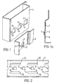
- a panel mount 1 is a generally angular section strip of metal and in one face has a three sided cutout 2 with the portion of the wall cut out, bent outwardly and bent back to form a tongue 3 which extends parallel to the wall in which the cutout 2 is formed.
- the tongue 3 can be inserted in any one of horizontally spaced apertures in a vertical side member 5 forming part of the frame of an electrical cabinet or can be inserted in any one of horizontally spaced apertures 6 in a brace 7 which can be secured to the side members of the frame of an electrical cabinet on one side of the cabinet to extend between a front side member and a rear side member.
- the apertures 4 or 6 are spaced at a pitch of 25 mm and thus the panel mount 1 can be supported on the side member 5 or the brace 7 by inserting the tongue 5 in an aperture 4 or 6 and then moving the panel mount 1 to cause the tongue 5 to move behind the web of the side member 5 or the brace 7 in which the aperture 4 or 6 is formed.
- the panel mount 1 does thus not need to be moved vertically to secure it and can be of the same length as the side members so as to extend completely between upper and lower frame members of the cabinet.
- a through aperture 8 may be provided in the panel mount 1 through which a pin or clip (not shown) can be inserted to engage in an aperture 9 provided alongside the aperture 4 or 6 in which the tongue 3 is engaged thereby to prevent return movement which would free the tongue from the aperture 4 or 6.
- Elongate slots 10 in the brace 7 can be used to secure the brace 7 by bolts to the side members, the length of the slots 10 allowing longitudinal shifting of the brace 7 with respect to the side members to allow stepless positioning of the panel mounts with respect to the side members 5.
- a chassis support 11 which comprises upper and lower flanges 12 and 13 above and below a vertical web 14.
- two cutouts 15 are formed by cutting around three sides and the member formed by each cutout is pressed out of the plane of the web 14 by a bend 16 and a further bend 17 and the tongue so formed which extends parallel to the web 14 but spaced therefrom is cut away to form upper and lower hooks 18, 19.
- the chassis support 11 can be engaged in two vertically spaced apertures and then moved downwardly so that the chassis support 11 is cantilevered from a pair of the hooks 18, 19 and can resist tilting forces applied thereto.
- chassis support 11 is shown as having two cutouts 15 and two pairs of hooks 18, 19 it is only envisaged that one or other of the pairs of hooks would be used at any one time but by providing two cutouts the chassis support 11 can act as a lefthanded chassis support or a righthanded chassis support.
- the chassis supports 11 are particularly suitable for supporting shelves in electrical cabinets.
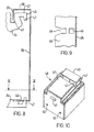
- an electrical cabinet 20 shown in exploded form, comprises an upper frame 21 and a lower frame 22 each formed by back-to-back U-shaped members 23 of tubular metal, four side members 24 extending between the upper frame 21 and the lower frame 22, an upper member 25 with cutouts 25a in three of the walls thereof, removable side panels 26 only one of which is shown and a removable door 27 which closes the front of the cabinet.
- the side panel 26 has an upper horizontal flange 28 with a return vertical flange 29, the panel 26, 28, 29 enveloping the two side members 24 on that side of the frame of the cupboard.
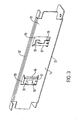
- FIG 7 shows the means whereby each of the U-shaped members 23 which extend horizontally can be mounted to the respective side members 24 which extend vertically.
- Two first holes 30 are punched or drilled in one wall 31 of the side member 24 and two first holes 32 are punched or drilled in one wall 33 of the U-shaped member 23.
- second holes 34 are then burst through the second wall 35 of the side members 24 and second holes 36 are burst through the second wall 37 of the U-shaped member 23. Bursting the holes in this way forms collars 38 at the outsides of the holes 34 and collars 39 at the outside of the holes 36.
- the holes 36 are then screw threaded.
- the collars 38 on the side members 24 are a push fit into the first holes 32 in the U-shaped member 23 so that when bolts (not shown) are inserted along the aligned axis 40 of each of the holes 30, 34, 32, 36 to pull the members 23, 24 tightly into engagement with one another, the members 23, 24 are locked accurately at right angles one to the other without any play such that even a tall framework of U-shaped members 23 and side members 24, for example two metres tall, can stand rigidly without a tendency for the upper frame to move sideways or from to rear due to the connections being less than entirely rigid.
- the collars 38 can however have a tapering formation such that great precision is not required in the formation of the holes and collars.
- each side member 24 is provided with a formation similar to that shown in Figure 10 at the righthand side thereof, that is to say it has a groove 41 in the upper face 42 stepped back from a front upper corner 43.
- the formation shown in Figure 10 is an extension piece to be hung on the upper or lower end of one of the side members 24 but the formation of the top end and bottom end of the side members 24 is the same as shown in Figure 10.
- the side panel 26 shown has its horizontal upper flange 28 overlapping the upper surface 42 of the side member 24 and its vertical flange 29 engaged in the groove 41 of the upper end of the side member 24.
- the side panel 26 has a horizontal flange 44 which, as shown in Figure 9, has, in alignment with each of the side members 24, apertures 45 and cutouts 46.
- a hook 47 is provided at each side of the side member 24 both at the upper and at the lower end .
- the hook 47 at the upper end has no function but that at the lower end engages in a respective one of the apertures 45.
- the method of engagement is that the panel 26 is first hooked onto the upper end of the side member so that the vertical flange 29 engages in the groove 41.
- the bottom end of the panel 26 is then pushed inwardly to engage the hooks 47 in the cutouts 46, a flared mouth of the cutouts 46 assisting this alignment.
- the side panel 26 is then raised slightly and pushed inwardly so that the hook 47 at the lower end of the side member 24 can engage in the respective aperture 45 in the bottom flange 44 of the side panel 26.
- the side panels 26 can thus quickly and easily be engaged with or disengaged from the framework of the cabinet. It will be seen that the hooks 47 taper down towards their free ends such that the weight of the panel engages the edges of the apertures 45 both with the outer and with the inner faces of the hook 47 so that vibration will not cause rattling of the panel.
- the extension pieces 48 have, in addition to the groove 41, the top face 42, the front edge 43 and the hooks 47 previously described, a bent out tongue 49 and aligned apertures 50, 51 by means of which they can be hooked onto and bolted to the outer face of the upper and lower ends of the side members 24.
- the extension pieces 48 are preferably 100 mm between the front edge 43 and the upper edge of the face in which the tongue 49 is provided whereby they can space the side panels 26 outwardly from the side members 24 by 100 mm to give an additional space for extra wiring or other purposes.
- a blanking plate can extend between the door of the cabinet and the extended position of the side panels 26 to fill 100 mm space at the front. If two adjacent cabinets are each provided with extension pieces 48 on their adjacent sides then the two cabinets can be accurately spaced apart by 200 mm to form a wiring space therebetween, a suitable blanking plate being provided to cover the space to the front.
Abstract
Description
- The invention relates to electrical cabinets.
- Electrical cabinets are used for receiving electronic and electrical components particularly but not exclusively for the operation of local data networks. The components such as sub-racks with electronic and electrical components, fans and other accessories are mounted within the cabinet on internal frames and the cabinets generally have side panels, a door and end panels and are mounted on a frame which preferably comprises upper and lower end members and vertically extending side members preferably provided one towards the front and the other towards the rear at each lateral side of the cabinet.
- According to one aspect of the invention, panel mounts, comprising members to extend vertically within the cabinet and having attachment means whereby panels can be mounted thereupon, are mounted to the side members of the cabinet by integral members which extend substantially parallel to the outer face of the panel mount at a spacing from the outer face and in a direction perpendicular to the longitudinal extent of the panel mount, such integral members each being engaged in a respective aperture in the side members or braces extending between the side members at one lateral side of the cabinet, followed by movement forwardly or rearwardly to secure the panel mount to the side members, retaining means such as a pin or stud then being inserted in aligned bores in the panel mounts and side members or braces to prevent return movement in said forward or rearward directions.
- Such method of securement can have the advantage over previously proposed methods which involved vertical movement of the panel mounts to secure them, that panel mounts of the full height of the side members can be secured to the side members where previously, due to the vertical movement experienced during the engagement, it was necessary for the panel mount to be significantly shorter than the side member. The panel mounts, which generally define a 483 mm (19 inch) wide mounting, can thus be secured at various locations in the depth of the cabinet and can extend for the full height of the side members.
- Preferably the apertures in the side members or braces are spaced at 25 mm horizontal spacing to set the locations at which the panel mounts can be secured at 25 mm spacings.
- Advantageously the braces have horizontally elongate slots therein in addition to the apertures whereby the braces can be secured by fastenings means, such as bolts, extending through the slots whereby the braces are horizontally movable with respect to the side members to permit the panel mounts to be secured at any desired location in the depth of the cabinet.
- According to another aspect of the invention in an electrical cabinet chassis supports, for example for supporting shelves, are provided in the form of cantilevers by providing the chassis supports with vertically spaced securing hooks which together are capable of preventing pivoting movement of a mounted article such as a shelf.
- The vertically spaced hooks may project longitudinally of a wall of the chassis support and parallel thereto to be engaged in respective apertures in a member from which they are to be supported.
- According to a further aspect of the invention, means to secure in abutment two rectangular section tubular metal members with their longitudinally axes mutually at right angles comprises punching or drilling at least two first holes in one wall of each of the metal members, acting through the first holes so formed to burst a respective second hole to each first hole in the opposite wall of the metal members to form an outwardly extending collar, screw threading the second holes in one of the members, engaging the collars of the other of the members in the first holes of said one of the members and engaging a bolt through the aligned first and second holes of said one and said other members to engage the screw thread in the collar of said one of the members to clamp the members together.
- According to a still further aspect of the invention, in an electrical cabinet a method of hanging a vertical side panel comprising engaging a top flange of the side panel, which top flange has a horizontal portion and a vertical return, over an upper suspension member of a frame of the cabinet and engaging a horizontal lower flange of the side panel with an upturned hook portion at the lower end of the frame of the cabinet so that the upturned hook projects upwardly through an aperture in the horizontal lower flange.
- Preferably the aperture in the horizontal lower flange is aligned with a cutout in a free edge of the flange and engagement is effected by engaging the hook in the cutout and then slightly raising the side panel while pushing it inwardly towards the cabinet before lowering the side panel downwardly onto the hook.
- The upper suspension member of the frame may be provided at the upper end of vertical side members of the frame or may be provided on extension pieces which are supported by the vertical side members and project laterally outwardly to extend the width of the cabinet beyond the side members. By using such extension pieces extra wiring accommodating spaces can be provided at one or both of the sides of a cabinet.
- The extension pieces can have hooks to engage over the upper edge of the side members, preferably in a recess so that such upper edges are below the upper extremity of the side members, and be bolted to the side members to retain them in position. Preferably each extension piece can be used as either an upper or a lower extension piece.
- The invention is diagrammatically illustrated by way of example in the accompanying drawings, in which:-
- Figure 1 is a perspective view of a panel mount with attachment means and a side member on which it can be mounted according to the invention;
- Figure 1a is a sectional end view of the panel mount of Figure 1;
- Figure 2 is an elevation of a brace to which the panel mount of Figure 1 can be secured;
- Figure 3 is a perspective view of an inner face of a chassis support with cantilever engagement hooks;
- Figure 4 is a view of the chassis support of Figure 3 from the other side;
- Figure 5 is an exploded view showing components of an electrical cabinet;
- Figure 6 is a view of the portion of Figure 5 indicated by the arrow VI but with a panel hung thereon;
- Figure 7 is a sectional view through two of the components shown in Figure 6;
- Figure 8 is a schematic view indicating hanging of a vertical side panel of an electrical cabinet by a method according to the invention;
- Figure 9 is a sectional view taken on line IX-IX of Figure 8;
- Figure 10 is a perspective view from above and an inner face of an extension member of an electrical cabinet according to the invention in a position to form an upper extension member;
- Figure 11 is a view from the other side of the extension member of Figure 10 also orientated so as to form an upper member; and
- Figure 12 is a view of the extension member shown in Figures 10 and 11 but in an orientation to form a lower extension member.
-
- Referring to the drawings and firstly to Figures 1 and 2, a panel mount 1 is a generally angular section strip of metal and in one face has a three sided cutout 2 with the portion of the wall cut out, bent outwardly and bent back to form a tongue 3 which extends parallel to the wall in which the cutout 2 is formed. The tongue 3 can be inserted in any one of horizontally spaced apertures in a
vertical side member 5 forming part of the frame of an electrical cabinet or can be inserted in any one of horizontally spacedapertures 6 in a brace 7 which can be secured to the side members of the frame of an electrical cabinet on one side of the cabinet to extend between a front side member and a rear side member. Theapertures 4 or 6 are spaced at a pitch of 25 mm and thus the panel mount 1 can be supported on theside member 5 or the brace 7 by inserting thetongue 5 in anaperture 4 or 6 and then moving the panel mount 1 to cause thetongue 5 to move behind the web of theside member 5 or the brace 7 in which theaperture 4 or 6 is formed. The panel mount 1 does thus not need to be moved vertically to secure it and can be of the same length as the side members so as to extend completely between upper and lower frame members of the cabinet. Athrough aperture 8 may be provided in the panel mount 1 through which a pin or clip (not shown) can be inserted to engage in anaperture 9 provided alongside theaperture 4 or 6 in which the tongue 3 is engaged thereby to prevent return movement which would free the tongue from theaperture 4 or 6. Elongateslots 10 in the brace 7 can be used to secure the brace 7 by bolts to the side members, the length of theslots 10 allowing longitudinal shifting of the brace 7 with respect to the side members to allow stepless positioning of the panel mounts with respect to theside members 5. - Referring to Figures 3 and 4, a
chassis support 11 is shown which comprises upper andlower flanges vertical web 14. In theweb 14 twocutouts 15 are formed by cutting around three sides and the member formed by each cutout is pressed out of the plane of theweb 14 by abend 16 and afurther bend 17 and the tongue so formed which extends parallel to theweb 14 but spaced therefrom is cut away to form upper andlower hooks chassis support 11 can be engaged in two vertically spaced apertures and then moved downwardly so that thechassis support 11 is cantilevered from a pair of thehooks chassis support 11 is shown as having twocutouts 15 and two pairs ofhooks chassis support 11 can act as a lefthanded chassis support or a righthanded chassis support. The chassis supports 11 are particularly suitable for supporting shelves in electrical cabinets. - Referring to Figure 5, an
electrical cabinet 20, shown in exploded form, comprises anupper frame 21 and a lower frame 22 each formed by back-to-back U-shaped members 23 of tubular metal, fourside members 24 extending between theupper frame 21 and the lower frame 22, anupper member 25 withcutouts 25a in three of the walls thereof,removable side panels 26 only one of which is shown and aremovable door 27 which closes the front of the cabinet. - As can be seen in Figure 6, the
side panel 26 has an upperhorizontal flange 28 with a returnvertical flange 29, thepanel side members 24 on that side of the frame of the cupboard. - Figure 7 shows the means whereby each of the
U-shaped members 23 which extend horizontally can be mounted to therespective side members 24 which extend vertically. Twofirst holes 30 are punched or drilled in onewall 31 of theside member 24 and twofirst holes 32 are punched or drilled in onewall 33 of the U-shapedmember 23. Operating through thefirst holes second holes 34 are then burst through thesecond wall 35 of theside members 24 andsecond holes 36 are burst through thesecond wall 37 of the U-shapedmember 23. Bursting the holes in this way formscollars 38 at the outsides of theholes 34 and collars 39 at the outside of theholes 36. Theholes 36 are then screw threaded. When themembers collars 38 on theside members 24 are a push fit into thefirst holes 32 in the U-shapedmember 23 so that when bolts (not shown) are inserted along thealigned axis 40 of each of theholes members members members 23 andside members 24, for example two metres tall, can stand rigidly without a tendency for the upper frame to move sideways or from to rear due to the connections being less than entirely rigid. Thecollars 38 can however have a tapering formation such that great precision is not required in the formation of the holes and collars. - Referring to Figures 8 to 12, the upper end of each
side member 24 is provided with a formation similar to that shown in Figure 10 at the righthand side thereof, that is to say it has agroove 41 in theupper face 42 stepped back from a frontupper corner 43. Actually the formation shown in Figure 10 is an extension piece to be hung on the upper or lower end of one of theside members 24 but the formation of the top end and bottom end of theside members 24 is the same as shown in Figure 10. - Referring to Figure 8, the
side panel 26 shown has its horizontalupper flange 28 overlapping theupper surface 42 of theside member 24 and itsvertical flange 29 engaged in thegroove 41 of the upper end of theside member 24. At the lower end theside panel 26 has ahorizontal flange 44 which, as shown in Figure 9, has, in alignment with each of theside members 24,apertures 45 andcutouts 46. At each side of theside member 24 both at the upper and at the lower end ahook 47 is provided. Thehook 47 at the upper end has no function but that at the lower end engages in a respective one of theapertures 45. With reference again to Figure 8 the method of engagement is that thepanel 26 is first hooked onto the upper end of the side member so that thevertical flange 29 engages in thegroove 41. The bottom end of thepanel 26 is then pushed inwardly to engage thehooks 47 in thecutouts 46, a flared mouth of thecutouts 46 assisting this alignment. Theside panel 26 is then raised slightly and pushed inwardly so that thehook 47 at the lower end of theside member 24 can engage in therespective aperture 45 in thebottom flange 44 of theside panel 26. Theside panels 26 can thus quickly and easily be engaged with or disengaged from the framework of the cabinet. It will be seen that thehooks 47 taper down towards their free ends such that the weight of the panel engages the edges of theapertures 45 both with the outer and with the inner faces of thehook 47 so that vibration will not cause rattling of the panel. - Referring now also to Figures 11 and 12, the
extension pieces 48 have, in addition to thegroove 41, thetop face 42, thefront edge 43 and thehooks 47 previously described, a bent outtongue 49 and alignedapertures side members 24. Theextension pieces 48 are preferably 100 mm between thefront edge 43 and the upper edge of the face in which thetongue 49 is provided whereby they can space theside panels 26 outwardly from theside members 24 by 100 mm to give an additional space for extra wiring or other purposes. A blanking plate can extend between the door of the cabinet and the extended position of theside panels 26 to fill 100 mm space at the front. If two adjacent cabinets are each provided withextension pieces 48 on their adjacent sides then the two cabinets can be accurately spaced apart by 200 mm to form a wiring space therebetween, a suitable blanking plate being provided to cover the space to the front.
Claims (4)
- A method of hanging a vertical side panel (26) of an electrical cabinet, comprising engaging a top flange of the side panel (26), which top flange has a horizontal portion (28), over an upper suspension member of a frame of the cabinet, and engaging a horizontal lower flange (44) of the side panel (26) with an upturned hook portion (47) at the lower end of the frame of the cabinet such that the upturned hook (47) projects upwardly through an aperture (45) in the lower flange (44), wherein the aperture (45) in the lower flange (44) is aligned with a cutout (46) in a free edge of the lower flange (44) and engagement is effected by engaging the hook (47) in the cutout (46) and then slightly raising the side panel (26) while pushing the same inwardly towards the cabinet before lowering the side panel (26) downwardly onto the hook (47).
- A method according to claim 1, wherein the upper suspension member of the frame of the cabinet is provided at the upper end of vertical side members (24) of the frame or on extension pieces (48) which are supported by the side members (24) and project laterally outwardly to extend beyond the side members (24).
- A method according to claim 2, wherein the extension pieces (48) have hooks (49) to engage over the upper edges of the side members (24), in a recess such that the upper edges are below the upper extremity of the side members (24), and be bolted to the side members (24) to be retained in position.
- A method according to claim 3, wherein each extension piece (48) can be used as either an upper or lower extension piece.
Applications Claiming Priority (3)
| Application Number | Priority Date | Filing Date | Title |
|---|---|---|---|
| GB9828841 | 1998-12-30 | ||
| GB9828841A GB2345239B (en) | 1998-12-30 | 1998-12-30 | Cabinet |
| EP99963639A EP1146803B1 (en) | 1998-12-30 | 1999-12-23 | Cabinet |
Related Parent Applications (1)
| Application Number | Title | Priority Date | Filing Date |
|---|---|---|---|
| EP99963639A Division EP1146803B1 (en) | 1998-12-30 | 1999-12-23 | Cabinet |
Publications (3)
| Publication Number | Publication Date |
|---|---|
| EP1355394A2 true EP1355394A2 (en) | 2003-10-22 |
| EP1355394A3 EP1355394A3 (en) | 2003-10-29 |
| EP1355394B1 EP1355394B1 (en) | 2005-04-20 |
Family
ID=10845170
Family Applications (3)
| Application Number | Title | Priority Date | Filing Date |
|---|---|---|---|
| EP20030016406 Expired - Lifetime EP1355394B1 (en) | 1998-12-30 | 1999-12-23 | Cabinet |
| EP99963639A Expired - Lifetime EP1146803B1 (en) | 1998-12-30 | 1999-12-23 | Cabinet |
| EP20030016405 Expired - Lifetime EP1354535B1 (en) | 1998-12-30 | 1999-12-23 | Cabinet |
Family Applications After (2)
| Application Number | Title | Priority Date | Filing Date |
|---|---|---|---|
| EP99963639A Expired - Lifetime EP1146803B1 (en) | 1998-12-30 | 1999-12-23 | Cabinet |
| EP20030016405 Expired - Lifetime EP1354535B1 (en) | 1998-12-30 | 1999-12-23 | Cabinet |
Country Status (7)
| Country | Link |
|---|---|
| US (3) | US7014155B1 (en) |
| EP (3) | EP1355394B1 (en) |
| AT (3) | ATE293379T1 (en) |
| AU (1) | AU1988100A (en) |
| DE (3) | DE69924893T2 (en) |
| GB (4) | GB2375289B (en) |
| WO (1) | WO2000040119A1 (en) |
Families Citing this family (17)
| Publication number | Priority date | Publication date | Assignee | Title |
|---|---|---|---|---|
| US6481582B1 (en) | 2001-06-04 | 2002-11-19 | Cooper Technologies Company | Rack |
| DE10240998B3 (en) * | 2002-09-05 | 2004-01-08 | Hilti Ag | Device for connecting mounting rails |
| US7306300B2 (en) * | 2003-03-28 | 2007-12-11 | Metal Fabricating Corporation | Cabinet runner side wall extension |
| US20070042638A1 (en) * | 2003-04-14 | 2007-02-22 | Choi Cheon S | Prefabricating rack frame |
| DE102005011761A1 (en) * | 2005-03-11 | 2006-09-14 | Baier & Schneider Gmbh & Co. Kg | Karteikasten |
| US7127924B1 (en) * | 2005-09-09 | 2006-10-31 | Gm Global Technology Operations, Inc. | Double action punch assembly for hydroforming die |
| US20080297015A1 (en) | 2007-05-30 | 2008-12-04 | Steelcase Inc. | Storage unit back stop and method |
| JP5088697B2 (en) * | 2008-09-02 | 2012-12-05 | 日本電気株式会社 | Rack mount equipment |
| ITTO20100286A1 (en) * | 2010-04-13 | 2011-10-14 | Indesit Co Spa | DOMESTIC COOKING APPLIANCE, PARTICULARLY AN OVEN |
| US8454036B2 (en) * | 2011-05-17 | 2013-06-04 | Apex Brands, Inc. | Tool kit mounting system |
| US9295327B2 (en) * | 2014-08-19 | 2016-03-29 | Haworth, Inc. | Side mounted drawer slide |
| GB2553774A (en) * | 2016-09-09 | 2018-03-21 | Nextco Ltd | A bar section for a portable modular bar |
| US11242690B2 (en) | 2018-01-19 | 2022-02-08 | Titcomb Brothers Manufacturing, Inc. | Loop tie for concrete forming panel systems |
| CA3088405A1 (en) | 2018-01-19 | 2019-07-25 | Titcomb Brothers Manufacturing, Inc. | Loop tie for concrete forming panel systems |
| US11002027B2 (en) * | 2018-01-19 | 2021-05-11 | Titcomb Brothers Manufacturing, Inc. | Stacking clip for concrete forming panel systems |
| DE102018130974A1 (en) * | 2018-12-05 | 2020-06-10 | ambigence GmbH & Co. KG | Furniture component and manufacturing method |
| EP3706265B1 (en) * | 2019-03-07 | 2021-10-27 | ELDON Group | Method for mounting a panel to an electrical cabinet and such cabinet |
Citations (1)
| Publication number | Priority date | Publication date | Assignee | Title |
|---|---|---|---|---|
| GB2160765A (en) * | 1984-06-27 | 1986-01-02 | Schaefer Gmbh Fritz | Improvements relating to cabinets or cubicles, suitable for switchgear |
Family Cites Families (47)
| Publication number | Priority date | Publication date | Assignee | Title |
|---|---|---|---|---|
| US3273720A (en) * | 1966-09-20 | Storage racks | ||
| US2065915A (en) * | 1934-11-08 | 1936-12-29 | Gen Fire Extinguisher Co | Method for forming branch nozzles on pipes |
| US2507859A (en) * | 1947-10-13 | 1950-05-16 | Ladish Drop Forge Co | Method of making pipe fittings |
| US2901781A (en) * | 1957-02-19 | 1959-09-01 | Sha Ag Solomon | Building elements |
| DE1848964U (en) * | 1961-09-20 | 1962-03-29 | Licentia Gmbh | DETACHABLE INSERT. |
| GB1217337A (en) * | 1967-04-22 | 1970-12-31 | Harris & Sheldon Display Ltd | Improvements relating to counters and the like structures |
| GB1119889A (en) * | 1967-06-12 | 1968-07-17 | Reiter Srl | A cabinet which can be assembled and method for making the same |
| US3574378A (en) * | 1969-05-26 | 1971-04-13 | James H Heywood | Strengthening insert and fastener for tubular constructions |
| US4036514A (en) * | 1972-06-26 | 1977-07-19 | E. I. Du Pont De Nemours And Company | Pipe fitting |
| US3788490A (en) * | 1972-08-22 | 1974-01-29 | Featherman | Erectible shelving |
| FR2203451A5 (en) * | 1972-10-12 | 1974-05-10 | Andersson Stig | |
| DE7833180U1 (en) * | 1978-11-08 | 1979-03-08 | Rittal-Werk Rudolf Loh Gmbh & Co Kg, 6341 Rittershausen | Switch or distribution cabinet with a swing frame |
| US4201428A (en) * | 1978-12-13 | 1980-05-06 | Marvel Metal Products Company | Cabinet assembly |
| US4278361A (en) * | 1979-04-11 | 1981-07-14 | Lyon Metal Products, Incorporated | Channel interconnection apparatus |
| GB2057044A (en) * | 1979-08-23 | 1981-03-25 | Davis & Quibell Ltd | Connector device |
| GB2072059A (en) * | 1980-03-19 | 1981-09-30 | Hotpoint Ltd | Domestic appliance cabinet |
| US4521041A (en) * | 1980-04-16 | 1985-06-04 | Cox Russell C | Pipe connection |
| US4345956A (en) * | 1980-04-16 | 1982-08-24 | Phillips Petroleum Company | Method for making a pipe connection or fitting |
| US4423978A (en) * | 1981-11-02 | 1984-01-03 | White Consolidated Industries, Inc. | Shelving construction |
| US4560079A (en) * | 1984-02-02 | 1985-12-24 | Burroughs Corporation | Equipment enclosure |
| JPS61156280A (en) * | 1984-12-28 | 1986-07-15 | 株式会社東芝 | Display monitor built-in electronic equipment cubicle |
| US4620684A (en) * | 1984-12-28 | 1986-11-04 | Coin Acceptors, Inc. | Support bracket assembly |
| DE8501810U1 (en) * | 1985-01-24 | 1985-04-25 | Rittal-Werk Rudolf Loh Gmbh & Co Kg, 6348 Herborn | Device for connecting side-by-side switch cabinets |
| DE3930161C1 (en) * | 1989-09-09 | 1990-09-13 | Rittal-Werk Rudolf Loh Gmbh & Co Kg, 6348 Herborn, De | |
| US5380083A (en) * | 1991-11-27 | 1995-01-10 | Federal-Hoffman, Inc. | Multifaceted modular enclosure frame with integral sub-panel guide system |
| US5292189A (en) * | 1991-11-27 | 1994-03-08 | Federal-Hoffman, Inc. | Sub-panel guide system for electrical enclosure |
| KR930019169A (en) | 1992-03-18 | 1993-10-18 | 우에다 히데끼 | Corner Bracket for Assembly Shelf |
| US6550879B1 (en) * | 1992-12-01 | 2003-04-22 | Herman Milles, Inc. | Cabinet structure |
| US5570940A (en) * | 1993-02-22 | 1996-11-05 | Viking Metal Cabinet Co., Inc. | Door system for a doorless storing structure |
| DE19520084C1 (en) * | 1995-06-01 | 1996-07-25 | Loh Kg Rittal Werk | Electrical switch cabinet with cladding panels fitted to profile frame |
| DE29521934U1 (en) * | 1995-10-04 | 1998-09-24 | Loh Kg Rittal Werk | Frame leg for a control cabinet |
| US5758988A (en) * | 1996-06-12 | 1998-06-02 | Theodorou; Antonis | Locking device and system for structural connection |
| US5941621A (en) * | 1997-02-28 | 1999-08-24 | Digital Equipment Corporation | Cabinet slide mounting bracket |
| GB2321004B (en) * | 1997-03-06 | 1998-12-02 | Willsher & Quick Ltd | Improvements in or relating to enclosures |
| FR2761206B1 (en) * | 1997-03-21 | 1999-05-14 | Schneider Electric Sa | METAL CHASSIS WITH HYPERSTATIC ASSEMBLY CORNER, PARTICULARLY FOR AN ELECTRICAL CABINET FRAMEWORK |
| DE19712362C1 (en) * | 1997-03-25 | 1998-07-30 | Loh Kg Rittal Werk | Device for fixing carrier rail on frame elements and assembly plates of switch-cabinet |
| US6430812B1 (en) * | 1997-08-28 | 2002-08-13 | The Boeing Company | Superplastic forming of tubing pull-outs |
| GB9803527D0 (en) * | 1998-02-19 | 1998-04-15 | Reddicliffe Edward A | A method of assembling a cabinet |
| JP3732941B2 (en) * | 1998-03-09 | 2006-01-11 | アルプス電気株式会社 | Electronics |
| US6230910B1 (en) * | 1998-03-31 | 2001-05-15 | Auto-Lok, Inc. | Self-locking beam clip |
| US6478391B1 (en) * | 1998-06-17 | 2002-11-12 | Sandusky Cabinets, Inc. | Cabinet |
| US6099095A (en) * | 1998-12-04 | 2000-08-08 | Irace; Francisco D. | Interlocking cabinet system |
| GB2345925B (en) * | 1999-01-19 | 2003-03-05 | Vero Electronics Ltd | Panel |
| US6352164B1 (en) * | 1999-07-20 | 2002-03-05 | Paltier, L.L.C. | Storage rack having locking beam-to-column connection |
| US6223908B1 (en) * | 1999-09-15 | 2001-05-01 | Homaco, Inc. | Adjustable communications equipment dual relay rack |
| US6357610B1 (en) * | 2000-11-03 | 2002-03-19 | Francisco D. Irace | Interlocking cabinet assembly |
| DE10240998B3 (en) * | 2002-09-05 | 2004-01-08 | Hilti Ag | Device for connecting mounting rails |
-
1998
- 1998-12-30 GB GB0218410A patent/GB2375289B/en not_active Expired - Fee Related
- 1998-12-30 GB GB0218409A patent/GB2376173B/en not_active Expired - Fee Related
- 1998-12-30 GB GB0218411A patent/GB2375702B/en not_active Expired - Fee Related
- 1998-12-30 GB GB9828841A patent/GB2345239B/en not_active Expired - Fee Related
-
1999
- 1999-12-23 AU AU19881/00A patent/AU1988100A/en not_active Abandoned
- 1999-12-23 AT AT03016405T patent/ATE293379T1/en not_active IP Right Cessation
- 1999-12-23 DE DE1999624893 patent/DE69924893T2/en not_active Expired - Lifetime
- 1999-12-23 AT AT03016406T patent/ATE293380T1/en not_active IP Right Cessation
- 1999-12-23 EP EP20030016406 patent/EP1355394B1/en not_active Expired - Lifetime
- 1999-12-23 EP EP99963639A patent/EP1146803B1/en not_active Expired - Lifetime
- 1999-12-23 EP EP20030016405 patent/EP1354535B1/en not_active Expired - Lifetime
- 1999-12-23 WO PCT/GB1999/004397 patent/WO2000040119A1/en active IP Right Grant
- 1999-12-23 AT AT99963639T patent/ATE291864T1/en not_active IP Right Cessation
- 1999-12-23 US US09/869,618 patent/US7014155B1/en not_active Expired - Fee Related
- 1999-12-23 DE DE1999624526 patent/DE69924526T2/en not_active Expired - Lifetime
- 1999-12-23 DE DE1999624894 patent/DE69924894T2/en not_active Expired - Lifetime
-
2003
- 2003-09-08 US US10/657,642 patent/US6921055B2/en not_active Expired - Lifetime
- 2003-09-08 US US10/657,349 patent/US7004553B2/en not_active Expired - Fee Related
Patent Citations (1)
| Publication number | Priority date | Publication date | Assignee | Title |
|---|---|---|---|---|
| GB2160765A (en) * | 1984-06-27 | 1986-01-02 | Schaefer Gmbh Fritz | Improvements relating to cabinets or cubicles, suitable for switchgear |
Also Published As
Similar Documents
| Publication | Publication Date | Title |
|---|---|---|
| EP1355394B1 (en) | Cabinet | |
| US6431668B1 (en) | Method of installing a telescopic shelf in a cabinet | |
| US6019331A (en) | Cantilever bracket assembly | |
| US9603273B2 (en) | Universal system for mounting rack doors | |
| US9084485B2 (en) | Mounting bracket | |
| JP3463184B2 (en) | Product display shelves | |
| JP3178292B2 (en) | Display fixture frame device | |
| JP3423769B2 (en) | Surface material mounting structure for drawer storage | |
| GB2228185A (en) | Display system | |
| JP4418067B2 (en) | Panel mounting structure for shelf equipment | |
| JPH1057158A (en) | Desk with shelf | |
| JPS5855817Y2 (en) | Shelves, etc. storage shelves | |
| JP3533561B2 (en) | Assembled shelves | |
| JP3223113B2 (en) | Showcase | |
| JPH0910041A (en) | Containing furniture | |
| JP3567359B2 (en) | Shelf equipment | |
| JPH0211872Y2 (en) | ||
| JP3532401B2 (en) | Apparatus for preventing falling of goods on goods shelves | |
| JP3187711B2 (en) | Display device connection structure | |
| JPH08256886A (en) | Assembly type book display device for display shelf | |
| JPH1077708A (en) | Furniture and low partition connecting device | |
| MXPA00012474A (en) | Telescopic guide with suspension bracket | |
| JPS61290909A (en) | Apparatus for fixing shelf plate | |
| JPH10117863A (en) | Rack system with rear face board |
Legal Events
| Date | Code | Title | Description |
|---|---|---|---|
| PUAI | Public reference made under article 153(3) epc to a published international application that has entered the european phase |
Free format text: ORIGINAL CODE: 0009012 |
|
| PUAL | Search report despatched |
Free format text: ORIGINAL CODE: 0009013 |
|
| 17P | Request for examination filed |
Effective date: 20030721 |
|
| AC | Divisional application: reference to earlier application |
Ref document number: 1146803 Country of ref document: EP Kind code of ref document: P |
|
| AK | Designated contracting states |
Kind code of ref document: A2 Designated state(s): AT BE CH CY DE DK ES FI FR GB GR IE IT LI LU MC NL PT SE |
|
| AK | Designated contracting states |
Kind code of ref document: A3 Designated state(s): AT BE CH CY DE DK ES FI FR GB GR IE IT LI LU MC NL PT SE |
|
| RIC1 | Information provided on ipc code assigned before grant |
Ipc: 7A 47B 96/06 A Ipc: 7A 47B 57/40 B |
|
| AKX | Designation fees paid |
Designated state(s): AT BE CH CY DE DK ES FI FR GB GR IE IT LI LU MC NL PT SE |
|
| GRAP | Despatch of communication of intention to grant a patent |
Free format text: ORIGINAL CODE: EPIDOSNIGR1 |
|
| GRAS | Grant fee paid |
Free format text: ORIGINAL CODE: EPIDOSNIGR3 |
|
| GRAA | (expected) grant |
Free format text: ORIGINAL CODE: 0009210 |
|
| AC | Divisional application: reference to earlier application |
Ref document number: 1146803 Country of ref document: EP Kind code of ref document: P |
|
| AK | Designated contracting states |
Kind code of ref document: B1 Designated state(s): AT BE CH CY DE DK ES FI FR GB GR IE IT LI LU MC NL PT SE |
|
| PG25 | Lapsed in a contracting state [announced via postgrant information from national office to epo] |
Ref country code: FI Free format text: LAPSE BECAUSE OF FAILURE TO SUBMIT A TRANSLATION OF THE DESCRIPTION OR TO PAY THE FEE WITHIN THE PRESCRIBED TIME-LIMIT Effective date: 20050420 Ref country code: AT Free format text: LAPSE BECAUSE OF FAILURE TO SUBMIT A TRANSLATION OF THE DESCRIPTION OR TO PAY THE FEE WITHIN THE PRESCRIBED TIME-LIMIT Effective date: 20050420 Ref country code: NL Free format text: LAPSE BECAUSE OF FAILURE TO SUBMIT A TRANSLATION OF THE DESCRIPTION OR TO PAY THE FEE WITHIN THE PRESCRIBED TIME-LIMIT Effective date: 20050420 Ref country code: CH Free format text: LAPSE BECAUSE OF FAILURE TO SUBMIT A TRANSLATION OF THE DESCRIPTION OR TO PAY THE FEE WITHIN THE PRESCRIBED TIME-LIMIT Effective date: 20050420 Ref country code: LI Free format text: LAPSE BECAUSE OF FAILURE TO SUBMIT A TRANSLATION OF THE DESCRIPTION OR TO PAY THE FEE WITHIN THE PRESCRIBED TIME-LIMIT Effective date: 20050420 Ref country code: BE Free format text: LAPSE BECAUSE OF FAILURE TO SUBMIT A TRANSLATION OF THE DESCRIPTION OR TO PAY THE FEE WITHIN THE PRESCRIBED TIME-LIMIT Effective date: 20050420 |
|
| REG | Reference to a national code |
Ref country code: GB Ref legal event code: FG4D |
|
| REG | Reference to a national code |
Ref country code: CH Ref legal event code: EP |
|
| REG | Reference to a national code |
Ref country code: IE Ref legal event code: FG4D |
|
| REF | Corresponds to: |
Ref document number: 69924894 Country of ref document: DE Date of ref document: 20050525 Kind code of ref document: P |
|
| PG25 | Lapsed in a contracting state [announced via postgrant information from national office to epo] |
Ref country code: SE Free format text: LAPSE BECAUSE OF FAILURE TO SUBMIT A TRANSLATION OF THE DESCRIPTION OR TO PAY THE FEE WITHIN THE PRESCRIBED TIME-LIMIT Effective date: 20050720 Ref country code: GR Free format text: LAPSE BECAUSE OF FAILURE TO SUBMIT A TRANSLATION OF THE DESCRIPTION OR TO PAY THE FEE WITHIN THE PRESCRIBED TIME-LIMIT Effective date: 20050720 Ref country code: DK Free format text: LAPSE BECAUSE OF FAILURE TO SUBMIT A TRANSLATION OF THE DESCRIPTION OR TO PAY THE FEE WITHIN THE PRESCRIBED TIME-LIMIT Effective date: 20050720 |
|
| PG25 | Lapsed in a contracting state [announced via postgrant information from national office to epo] |
Ref country code: ES Free format text: LAPSE BECAUSE OF FAILURE TO SUBMIT A TRANSLATION OF THE DESCRIPTION OR TO PAY THE FEE WITHIN THE PRESCRIBED TIME-LIMIT Effective date: 20050731 |
|
| PG25 | Lapsed in a contracting state [announced via postgrant information from national office to epo] |
Ref country code: PT Free format text: LAPSE BECAUSE OF FAILURE TO SUBMIT A TRANSLATION OF THE DESCRIPTION OR TO PAY THE FEE WITHIN THE PRESCRIBED TIME-LIMIT Effective date: 20050920 |
|
| REG | Reference to a national code |
Ref country code: CH Ref legal event code: PL |
|
| NLV1 | Nl: lapsed or annulled due to failure to fulfill the requirements of art. 29p and 29m of the patents act | ||
| PG25 | Lapsed in a contracting state [announced via postgrant information from national office to epo] |
Ref country code: IE Free format text: LAPSE BECAUSE OF NON-PAYMENT OF DUE FEES Effective date: 20051223 Ref country code: CY Free format text: LAPSE BECAUSE OF FAILURE TO SUBMIT A TRANSLATION OF THE DESCRIPTION OR TO PAY THE FEE WITHIN THE PRESCRIBED TIME-LIMIT Effective date: 20051223 |
|
| PG25 | Lapsed in a contracting state [announced via postgrant information from national office to epo] |
Ref country code: MC Free format text: LAPSE BECAUSE OF NON-PAYMENT OF DUE FEES Effective date: 20051231 Ref country code: LU Free format text: LAPSE BECAUSE OF NON-PAYMENT OF DUE FEES Effective date: 20051231 |
|
| PLBE | No opposition filed within time limit |
Free format text: ORIGINAL CODE: 0009261 |
|
| STAA | Information on the status of an ep patent application or granted ep patent |
Free format text: STATUS: NO OPPOSITION FILED WITHIN TIME LIMIT |
|
| ET | Fr: translation filed | ||
| 26N | No opposition filed |
Effective date: 20060123 |
|
| REG | Reference to a national code |
Ref country code: IE Ref legal event code: MM4A |
|
| REG | Reference to a national code |
Ref country code: GB Ref legal event code: 732E |
|
| REG | Reference to a national code |
Ref country code: FR Ref legal event code: TP |
|
| PGFP | Annual fee paid to national office [announced via postgrant information from national office to epo] |
Ref country code: GB Payment date: 20131227 Year of fee payment: 15 Ref country code: DE Payment date: 20131230 Year of fee payment: 15 |
|
| PGFP | Annual fee paid to national office [announced via postgrant information from national office to epo] |
Ref country code: IT Payment date: 20131228 Year of fee payment: 15 Ref country code: FR Payment date: 20131217 Year of fee payment: 15 |
|
| REG | Reference to a national code |
Ref country code: DE Ref legal event code: R119 Ref document number: 69924894 Country of ref document: DE |
|
| GBPC | Gb: european patent ceased through non-payment of renewal fee |
Effective date: 20141223 |
|
| REG | Reference to a national code |
Ref country code: FR Ref legal event code: ST Effective date: 20150831 |
|
| PG25 | Lapsed in a contracting state [announced via postgrant information from national office to epo] |
Ref country code: DE Free format text: LAPSE BECAUSE OF NON-PAYMENT OF DUE FEES Effective date: 20150701 Ref country code: GB Free format text: LAPSE BECAUSE OF NON-PAYMENT OF DUE FEES Effective date: 20141223 |
|
| PG25 | Lapsed in a contracting state [announced via postgrant information from national office to epo] |
Ref country code: FR Free format text: LAPSE BECAUSE OF NON-PAYMENT OF DUE FEES Effective date: 20141231 |
|
| PG25 | Lapsed in a contracting state [announced via postgrant information from national office to epo] |
Ref country code: IT Free format text: LAPSE BECAUSE OF NON-PAYMENT OF DUE FEES Effective date: 20141223 |