EP1335196A2 - Evacuation chamber for filtering and removing liquids - Google Patents
Evacuation chamber for filtering and removing liquids Download PDFInfo
- Publication number
- EP1335196A2 EP1335196A2 EP03010843A EP03010843A EP1335196A2 EP 1335196 A2 EP1335196 A2 EP 1335196A2 EP 03010843 A EP03010843 A EP 03010843A EP 03010843 A EP03010843 A EP 03010843A EP 1335196 A2 EP1335196 A2 EP 1335196A2
- Authority
- EP
- European Patent Office
- Prior art keywords
- vacuum chamber
- vacuum
- separator
- liquids
- chamber according
- Prior art date
- Legal status (The legal status is an assumption and is not a legal conclusion. Google has not performed a legal analysis and makes no representation as to the accuracy of the status listed.)
- Granted
Links
- 239000007788 liquid Substances 0.000 title claims abstract description 153
- 238000001914 filtration Methods 0.000 title claims description 28
- 238000010438 heat treatment Methods 0.000 claims description 57
- 238000009423 ventilation Methods 0.000 claims description 17
- 239000004020 conductor Substances 0.000 claims 1
- 238000000034 method Methods 0.000 abstract description 17
- 238000005086 pumping Methods 0.000 abstract description 7
- 239000000126 substance Substances 0.000 description 14
- LFQSCWFLJHTTHZ-UHFFFAOYSA-N Ethanol Chemical compound CCO LFQSCWFLJHTTHZ-UHFFFAOYSA-N 0.000 description 12
- 238000001035 drying Methods 0.000 description 10
- 238000005406 washing Methods 0.000 description 10
- 238000011282 treatment Methods 0.000 description 9
- 230000005484 gravity Effects 0.000 description 8
- 238000009835 boiling Methods 0.000 description 6
- 238000001704 evaporation Methods 0.000 description 5
- 150000007523 nucleic acids Chemical class 0.000 description 5
- 102000039446 nucleic acids Human genes 0.000 description 5
- 108020004707 nucleic acids Proteins 0.000 description 5
- 238000000926 separation method Methods 0.000 description 5
- 239000012472 biological sample Substances 0.000 description 4
- 239000007789 gas Substances 0.000 description 4
- 239000000463 material Substances 0.000 description 4
- 238000005273 aeration Methods 0.000 description 3
- 238000010276 construction Methods 0.000 description 3
- 238000010828 elution Methods 0.000 description 3
- 230000008020 evaporation Effects 0.000 description 3
- 230000000903 blocking effect Effects 0.000 description 2
- 238000002955 isolation Methods 0.000 description 2
- 239000011159 matrix material Substances 0.000 description 2
- 230000001105 regulatory effect Effects 0.000 description 2
- 230000002745 absorbent Effects 0.000 description 1
- 239000002250 absorbent Substances 0.000 description 1
- 238000004458 analytical method Methods 0.000 description 1
- 230000009286 beneficial effect Effects 0.000 description 1
- 230000031018 biological processes and functions Effects 0.000 description 1
- 238000004113 cell culture Methods 0.000 description 1
- 238000001311 chemical methods and process Methods 0.000 description 1
- 238000009833 condensation Methods 0.000 description 1
- 230000005494 condensation Effects 0.000 description 1
- 238000012864 cross contamination Methods 0.000 description 1
- 230000000694 effects Effects 0.000 description 1
- 230000008030 elimination Effects 0.000 description 1
- 238000003379 elimination reaction Methods 0.000 description 1
- 238000005516 engineering process Methods 0.000 description 1
- 230000007613 environmental effect Effects 0.000 description 1
- 238000002309 gasification Methods 0.000 description 1
- 239000012528 membrane Substances 0.000 description 1
- 238000005497 microtitration Methods 0.000 description 1
- 230000000149 penetrating effect Effects 0.000 description 1
- 239000013612 plasmid Substances 0.000 description 1
- 239000000523 sample Substances 0.000 description 1
- 230000003584 silencer Effects 0.000 description 1
- 239000000725 suspension Substances 0.000 description 1
Images


Classifications
-
- B—PERFORMING OPERATIONS; TRANSPORTING
- B01—PHYSICAL OR CHEMICAL PROCESSES OR APPARATUS IN GENERAL
- B01L—CHEMICAL OR PHYSICAL LABORATORY APPARATUS FOR GENERAL USE
- B01L3/00—Containers or dishes for laboratory use, e.g. laboratory glassware; Droppers
- B01L3/50—Containers for the purpose of retaining a material to be analysed, e.g. test tubes
- B01L3/502—Containers for the purpose of retaining a material to be analysed, e.g. test tubes with fluid transport, e.g. in multi-compartment structures
- B01L3/5025—Containers for the purpose of retaining a material to be analysed, e.g. test tubes with fluid transport, e.g. in multi-compartment structures for parallel transport of multiple samples
- B01L3/50255—Multi-well filtration
-
- B—PERFORMING OPERATIONS; TRANSPORTING
- B01—PHYSICAL OR CHEMICAL PROCESSES OR APPARATUS IN GENERAL
- B01L—CHEMICAL OR PHYSICAL LABORATORY APPARATUS FOR GENERAL USE
- B01L2300/00—Additional constructional details
- B01L2300/08—Geometry, shape and general structure
- B01L2300/0809—Geometry, shape and general structure rectangular shaped
- B01L2300/0829—Multi-well plates; Microtitration plates
-
- B—PERFORMING OPERATIONS; TRANSPORTING
- B01—PHYSICAL OR CHEMICAL PROCESSES OR APPARATUS IN GENERAL
- B01L—CHEMICAL OR PHYSICAL LABORATORY APPARATUS FOR GENERAL USE
- B01L2300/00—Additional constructional details
- B01L2300/18—Means for temperature control
-
- B—PERFORMING OPERATIONS; TRANSPORTING
- B01—PHYSICAL OR CHEMICAL PROCESSES OR APPARATUS IN GENERAL
- B01L—CHEMICAL OR PHYSICAL LABORATORY APPARATUS FOR GENERAL USE
- B01L2400/00—Moving or stopping fluids
- B01L2400/04—Moving fluids with specific forces or mechanical means
- B01L2400/0475—Moving fluids with specific forces or mechanical means specific mechanical means and fluid pressure
- B01L2400/0487—Moving fluids with specific forces or mechanical means specific mechanical means and fluid pressure fluid pressure, pneumatics
- B01L2400/049—Moving fluids with specific forces or mechanical means specific mechanical means and fluid pressure fluid pressure, pneumatics vacuum
-
- G—PHYSICS
- G01—MEASURING; TESTING
- G01N—INVESTIGATING OR ANALYSING MATERIALS BY DETERMINING THEIR CHEMICAL OR PHYSICAL PROPERTIES
- G01N1/00—Sampling; Preparing specimens for investigation
- G01N1/28—Preparing specimens for investigation including physical details of (bio-)chemical methods covered elsewhere, e.g. G01N33/50, C12Q
- G01N1/40—Concentrating samples
- G01N1/405—Concentrating samples by adsorption or absorption
-
- G—PHYSICS
- G01—MEASURING; TESTING
- G01N—INVESTIGATING OR ANALYSING MATERIALS BY DETERMINING THEIR CHEMICAL OR PHYSICAL PROPERTIES
- G01N35/00—Automatic analysis not limited to methods or materials provided for in any single one of groups G01N1/00 - G01N33/00; Handling materials therefor
- G01N2035/00465—Separating and mixing arrangements
- G01N2035/00475—Filters
- G01N2035/00485—Filters combined with sample carriers
-
- Y—GENERAL TAGGING OF NEW TECHNOLOGICAL DEVELOPMENTS; GENERAL TAGGING OF CROSS-SECTIONAL TECHNOLOGIES SPANNING OVER SEVERAL SECTIONS OF THE IPC; TECHNICAL SUBJECTS COVERED BY FORMER USPC CROSS-REFERENCE ART COLLECTIONS [XRACs] AND DIGESTS
- Y10—TECHNICAL SUBJECTS COVERED BY FORMER USPC
- Y10S—TECHNICAL SUBJECTS COVERED BY FORMER USPC CROSS-REFERENCE ART COLLECTIONS [XRACs] AND DIGESTS
- Y10S159/00—Concentrating evaporators
- Y10S159/16—Vacuum
Definitions
- the invention relates to a vacuum chamber for automated filtering and removal of liquids and liquid residues.
- molecular biological processes such as the Filtering, washing and eluting nucleic acids or isolating RNA and / or DNA can be done automatically.
- a filter module designated support body used which arranged a variety of arranged in matrix form Have containers.
- These containers have an inlet opening at the top and point in lower part on an outlet opening.
- Filter body in the form of suitable membranes or filters used to bind the analyzing substances in the liquid samples are suitable.
- a single pipetting device is first given cell cultures in suspension, lysed and then placed in the containers of the carrier plate by means of a pipetting device. Then the carrier plates with the filled containers are placed on one Vacuum chamber placed that the outlet openings of the containers in the Protrude into the vacuum chamber. By applying a vacuum in the Vacuum chamber, the liquids in the containers through the filter body the vacuum chamber sucked. The ones to be analyzed remain in the filter bodies Hang components along with other components of the liquid sample. To the To obtain components of the liquid samples of interest, you must first the substances not required are washed out of the filter bodies. For this the washing solutions of different concentrations are pipetted into the containers. By means of these washing solutions, part of the components of the Liquid samples detached from the filter bodies. Then using a Elution solution, the components of interest are removed from the filter bodies and collected.
- the solutions used in the individual steps can, however, the in Contaminate the solution used in the following step.
- the carrier bodies or microtitration plates were previously opened several times by hand dropped on a pad of absorbent material to shake off these drops.
- the removal of the residual liquids was carried out Automated creation of a vacuum.
- the object of the invention is therefore to provide a vacuum chamber, the first is the filtering of liquids under negative pressure and the collection of the filtered liquids, but also the removal of Liquids, especially of liquid residues in the filter body area or on the Make the openings in the containers as complete as possible and in a short time can to avoid the problems known in the prior art.
- the vacuum chamber has a heating plate for heating Areas of the vacuum chamber.
- the heating plate is preferably in the bottom region of the Vacuum chamber arranged.
- the heating plate particularly preferably has holes.
- the vacuum chamber according to the invention preferably has a vacuum pump and a separator, wherein the vacuum chamber by means of a first line with the Connected separator and a first between the vacuum chamber and separator Locking device is arranged, and wherein the vacuum chamber by means of a second Line is connected to the vacuum pump, so that the vacuum chamber below Bypassing the separator can be evacuated.
- Liquids are basically understood to mean any substance that is in is in liquid form or is in a liquid.
- chemical and / or biological samples or liquids chemical and / or biological samples and those for the treatment of chemical and / or required biological samples.
- Treating liquids in a vacuum chamber are different activities related to liquids and / or liquid residues in one
- the vacuum chamber e.g. pull a liquid through a filter
- Remove liquid residues by pumping or evaporation, which is also preferred as Drying of the vacuum chamber can be called, as well as liquids in one Collect the vessel or clear the way to a separator.
- a separator is to be understood in particular as a device, the liquids can collect and collect in a separator vessel.
- the separation vessel can preferably large enough to hold a few 100 ml of liquid.
- the catch e.g. thereby achieved that the separator below a liquid to be collected is arranged so that the liquid due to gravity in a separator vessel flows or falls; alternatively, the liquid is also collected by Material structures achieved that correspond to the liquid flow, e.g. by a vacuum pump is generated, oppose so that the liquids on the material structure separate and flow or fall to the separator vessel.
- the separator consists of a closed separator vessel that comes from above has two tubes that openly protrude into the separation vessel.
- the one tube is an inflow pipe through which the liquids by gravity and / or suction through a Vacuum pump is transported into the separation vessel and collected; the other Tube is the outlet tube to which a vacuum pump is connected.
- the outlet pipe ends above the liquid level, so that in the separation vessel collected liquids cannot reach the vacuum pump. Is preferred the opening of the outlet pipe above the opening of the inlet pipe arranged. However, other methods of separating liquids can also be used are preferably used. There can also be several separators in different Arrangements can be attached to the vacuum chamber or to the lines.
- the vacuum chamber without a separator is evacuated by a (or also several) vacuum pumps that are connected to the vacuum chamber, wherein the separator is separated from the vacuum chamber or the vacuum pump.
- the Separation is advantageously achieved by a locking device.
- Under Locking device is e.g. to understand a device with input and output that can be switched between passage or blocking.
- preferred Locking device is e.g. a vacuum-compatible shut-off valve. Is the separator from the Vacuum chamber separated so that there are no larger with the vacuum chamber in There are related liquid reservoirs in the vacuum chamber, so with the vacuum pump can quickly reach a high vacuum, the remaining one Liquid residue evaporates faster.
- the device having the vacuum chamber according to the invention can be used, a first line, which connects the vacuum chamber to a first vacuum pump via the separator.
- the pump promotes the transport of the liquids into the separator.
- a closing device is arranged between the separator and the vacuum pump again e.g. can be a vacuum-compatible shut-off valve.
- the vacuum chamber including the separator, is pumped out. Is the The separator is filled with liquid, so the evacuation process runs slowly because the The liquid lying in the separator supplies gas by evaporation for a long time. As long as the liquid in the separator has not completely evaporated, neither can high negative pressure can be achieved. This is avoided by the locking device.
- the device which is connected to the vacuum chamber according to the invention can be used, a second line, which connects the vacuum chamber to a second vacuum pump. Since no one here Liquid-filled separators installed in the line can be used for the same Pumping power with this line quickly evacuated the vacuum chamber and the Liquid residues are removed quickly, provided that the separator through the Locking device is separated from the vacuum chamber.
- the second also preferred Line at least one locking device that ensures that in the filtering process no liquid gets into the vacuum pump from the vacuum chamber.
- the first line between Separators and vacuum pumps and the second line are preferred by a Line T-piece folded into a line before it in the intake of the Vacuum pump open.
- the first line between separators is also preferred and vacuum chamber and second line, also through a line T-piece, folded to open with a line in the vacuum chamber.
- the first and second closing devices are preferred by a 3/2-way valve replaced to reduce the number of active components to be controlled.
- the 3/2-way valve is built into the piping system so that the inlet of the 3/2-way valve connected to the vacuum chamber while the first of the two Outputs of the 3/2-way valve to the separator and the second output directly to Vacuum pump leads.
- the 3/2-way valve advantageously replaces two connections to the Vacuum chamber or the first line T-piece.
- the 3/2-way valve can be in switch two switch positions, being in the first switch position with the input connects the first exit, blocking the second exit while it is in the second switch position connects the input to the second output and the first exit blocked.
- the further first are advantageous and another second closing device replaced by another 3/2-way valve to the To reduce the number of active components to be controlled.
- the further 3/2-way valve is preferably installed in the line system so that the input of the Another 3/2-way valve is connected to the vacuum pump, while the first one two outputs of the further 3/2-way valve to the separator and the second output leads past the separator to the vacuum chamber. This allows the use of a Vacuum pump.
- the further 3/2-way valve also advantageously replaces the second line Tee.
- the 3/2-way valve can preferably be switched to two switch positions, in the first switch position it connects the input to the first output and the second output blocked and the input in the second switch position connects the second output and blocks the first output.
- the vacuum chamber Part of a device for filtering liquids.
- the vacuum in the Vacuum chamber is preferably used to hold liquids in containers Filter bodies have been entered into the inlet openings through the filter bodies suck.
- the vacuum chamber is preferably set up for this purpose so that it has an opening at the top into which one or more of these containers are to be filtered Liquids can be let into the vacuum chamber.
- the top opening the vacuum chamber and the containers are set up so that the container and upper Seal the opening in a gas-tight manner. As long as liquid above the filter body is in the container, the vacuum chamber is still sealed gas-tight, so that a vacuum pump can create a vacuum in the vacuum chamber.
- This negative pressure sucks the liquids accommodated in the containers through the Filter body, so that a quick filtering is possible. Only when the liquid in the Containers have been completely sucked through the filter and thus the filtering atmospheric air can get through the filters into the vacuum chamber.
- Filtering is to be understood in a broader sense here: it means sucking Liquids in named containers through the filter body using a Vacuum, this process also when washing filter residues with a Solution, especially with ethanol, or when eluting filter residues with a Elution solution expires.
- the closing devices especially the check valves and / or the 3/2-way valves of the lines are preferably switched so that the separator is connected to the vacuum chamber and the vacuum chamber with separator is evacuated.
- the liquid sucked through the filter body flows through Gravity or pump suction, to the separator. It has to be done Care should be taken to ensure that no liquid is drawn into the vacuum pump by suction or gravity device. To prevent this, it is preferred to pump through the separator, see above that the liquid is trapped there, or the inlet of the pump nozzle in the Vacuum chamber is located at a location to which the liquids despite pump suction cannot get.
- the two 3/2-way valves are preferably both in the first switch position switched so that evacuation is carried out with the separator.
- liquids can be eliminated be, especially liquid residues that do not get into the separator when filtering have flowed out, but in the filter bodies or at the outlets of the containers Drops are stuck or on the surfaces inside the vacuum chamber are left behind. Since these liquid residues, especially in the filter bodies, a Falsify analysis, these must be reduced to a minimum. Is preferred with the help of a vacuum through a connected to the vacuum chamber Vacuum pump lowers the boiling point of the liquid so that the liquid accelerated gasification. In order to maximize the negative pressure, a lid is preferred the vacuum chamber applied to the top opening of the vacuum chamber gas-tight, otherwise the chamber would be open. The gas is through the Vacuum pump sucked off.
- the removal of liquids preferably takes place in that Closing devices and valves separate the separator from the vacuum chamber and a vacuum pump that is not connected to a separator Vacuum chamber evacuated. Because in this way the separator is not always new gas can deliver through evaporating liquid into the vacuum chamber, the Vacuum in the chamber increases and thus the boiling point of the liquid residue be further reduced. In this way, the residual liquid is evaporated faster and less residue. A residue-free removal of the residual liquids is especially necessary in the containers and filter bodies, since there are often small ones Amounts of substances to be analyzed are located by residual liquids would be contaminated and therefore would give false results. Doing so for the elimination of liquids the two 3/2-way valves in the second Switch position switched so that evacuation is carried out without a separator.
- the vacuum chamber is advantageous or connected at another suitable place a ventilation valve, so that the Vacuum chamber can be ventilated.
- the ventilation takes place e.g. after one step for liquid removal, as for liquid removal multiple cycle of pumping and aeration has proven to be advantageous.
- Throttle valve attached, with which a too rapid pressure increase during ventilation, which the Damage the vacuum chamber or the liquids in the vacuum chamber or confused, can be avoided.
- the device preferably comprises a central control for Closing devices and check valves, 3/2-way valves, ventilation valve and / or Vacuum pumps.
- a central control for Closing devices and check valves, 3/2-way valves, ventilation valve and / or Vacuum pumps.
- the device can be monitored and convenient to be controlled.
- processes such as filtering, liquid removal and ventilation automated, reproducibly repeated and thus easier to optimize. Incorrect operations are also rarely used in a fully automatic process.
- the vacuum chamber can preferably hold containers with which Filtering can be carried out:
- the containers preferably have a Inlet opening, filter body and an outlet opening so that in the inlet opening Liquids entered by gravity or vacuum suction through the filter Outlet opening can reach.
- These containers are preferably in a matrix Structure attached to a support plate, so that preferably multiple filtering can be carried out in parallel.
- the holes in the heating plate are preferably so formed that the containers protrude into the holes with a lower portion can. The heating plate with the holes thereby preferably heats the containers Filter body area and at the outlet area and thus contributes to an accelerated Removal of liquid residues in the filter area and outlet area.
- the heating plate can preferably also be used to control the temperature analyzing liquids in the containers. Besides, that will Avoid splashing of liquid on the top surface of the heating plate as well as the Cross-contamination possibilities reduced.
- the heating plate is preferred by a heating tape which is in the outer region of the Heating plate is attached, heated.
- the heating tape is around led the heating plate around.
- the heating plate is preferably made of a thermally conductive one Material so that the temperature is largely uniform over the entire area is distributed.
- the vacuum chamber has in the area of the Side walls at least one heating element.
- the heating element serves this purpose Need to heat the side walls, which is beneficial to the condensation liquids and Liquid residues on the colder ones in relation to the heating plate and filter bodies Side walls prevented. Also for heating the liquids in the containers the heating element can preferably serve.
- the heating element is preferably a Heating tape, which is preferably attached in the vacuum chamber inner wall.
- At least one temperature sensor is preferred in the vacuum chamber attached, with which the temperature in the vacuum chamber can be read.
- An electronic unit preferably controls the temperature on the heating plate and / or the heating elements, what a gentle treatment of the liquids and a quickest possible drying process is advantageous.
- the electronic control the heating plate and / or heating element is still useful for an automated Sequence of heating cycles.
- the vacuum chamber is preferably sealed airtight in order to be as possible to achieve good negative pressure, which clearly eliminates the liquid residues accelerated.
- the method is preferably used to filter the filter drying filter residues, i.e. if the containers within the Vacuum chamber are arranged.
- a lid is preferred, which the Containers covered and sealed gas-tight with the opening in the vacuum chamber, placed on the vacuum chamber.
- the vacuum chamber is preferably connected to a vacuum pump and the The separator is separated from the vacuum chamber and vacuum pump. Prefers the vacuum pump is then switched on.
- the absence of the separator from the to evacuating vacuum chamber improves the vacuum since there is no evaporating Liquid from the separator can enter the vacuum chamber to be evacuated. This significantly increases the speed at which the liquids to be removed are removed evaporate and can be pumped out.
- the vacuum chamber is preferably vented after a period of pumping. This step is preferably carried out when removing the liquids accelerated by a repeated cycle of pumping and aeration shall be.
- the process preferably removes ethanol, which is a preferred washing solution for nucleic acids and the isolation of liquids with DNA or RNA.
- the vacuum chamber is preferably used to remove the liquids Heating elements or the heating plate heated to accelerate the evaporation. It is preferably heated to a temperature above the boiling point, which leads to leads to the fastest possible removal of liquids. Since the boiling point is one If liquid falls with increasing negative pressure, a good vacuum already allows boiling at low temperatures.
- the method is preferably controlled by an electronic unit, as a result of this the temperature in the lower pressure chamber, the pumping times and times of the Ventilation and the heating temperatures to be set in the vacuum chamber are optimal can be regulated and reproducibly and automated.
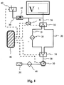
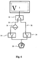
- Fig. 1 shows schematically an embodiment of a device for the treatment of Liquids in a vacuum chamber, especially for filtering and removing Liquids.
- the essential elements are the vacuum chamber 1, the separator 16, the vacuum pump 30 and the 3/2-way valve 32 and the further 3/2-way valve 34. If both 3/2-way valves are switched to the first switch position, then that is Vacuum pump 30 exclusively via the separator 16 with the vacuum chamber connected. If both 3/2-way valves are switched to the second switch position, then the vacuum pump 30 only bypassing the separator with the Vacuum chamber connected.
- the throttle valve e.g. the speed at which ventilation of the vacuum chamber is to be set.
- a pressure sensor 44 is also shown, which to the Ventilation line is connected. With the pressure sensor 44 in the Pressure chamber prevailing pressure measured and monitored. Basically it is it is not essential how long the ventilation line is and where it is in the vacuum chamber opens. With a suitable structure, you may also be able to choose one Aeration line can be dispensed with if ventilation valve and / or Attach throttle valve and / or pressure sensor directly to the vacuum housing. It is crucial that the ventilation valve can vent the vacuum chamber and preferably the pressure in the vacuum chamber is measured using the pressure sensor can be.
- the further separator 48 has the function that Free the air emitted from the pump and, if necessary, the air released by the pump Vacuum pump to filter air discharged to the rear.
- the electronic control 46 is shown that the active components of the Systems, especially 3/2-way valves, ventilation valve, pump and pressure sensor, reads and / or regulates.
- electronic control 46 is not limited to that shown Limited components; the control unit can also control the temperature in the Regulated vacuum chamber or lifting and putting the cover 66 on the Vacuum chamber are caused.
- the electronic control the Liquid treatment process, e.g. a successive filter or Drying procedure, automated and optimized. This is not just a time saver, but enables the greatest possible reproducibility and freedom from errors regarding the Service.
- Fig. 1 shows an embodiment of the device for treating liquids in a vacuum chamber.
- the two 3/2-way valves By switching the two 3/2-way valves to the first Switch position can create a vacuum in the vacuum chamber 1, the e.g. is used for filtering, and the liquid lead to the separator 16.
- Fig. 1 is an embodiment of the device. Further designs are in the figures 2 to 8 shown.
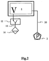
- Fig. 2 shows an embodiment of a minimal structure with which both filtered under vacuum and dried bypassing the separator can. If the first closing device 12 is switched to passage, it can be filtered Liquid, guided by gravity, in the below the filter body Separator 16 flow. The vacuum for the filtering is created by the vacuum pump 2, which is connected to the vacuum chamber 1 by a line 20. In this structure must be ensured that the line 20 before the through the Liquids entering the filter body are protected so that no liquid gets into the Vacuum pump can get.
- first Line 10 and the second line 20 are connected to the vacuum chamber.
- she can be connected side by side or on the side of the vacuum chamber or also e.g. also merged to the via a T-line piece Vacuum chamber can be connected.
- the line leading to the separator is in usually connected to the bottom of the vacuum chamber around which is at the bottom to remove enriching liquids.
- the bottom of the chamber is preferably conical tapered, which promotes the drainage of the liquids. In this case the drain conveniently located at the lowest point.
- a second, on the ground attached process is then technically more complex to implement.
- the second process in particular that for vacuum pump 2, can then advantageously be attached to the side be made, as this makes it difficult for the liquid to penetrate this line.
- the connection of the first line 10 and the second line 20 is only on it make sure that the device has no functional restrictions.
- the Locking device 12 locked and preferably a gas-tight cover on the Vacuum chamber attached. As described in Fig. 1, the vacuum chamber can now are pumped under significantly better negative pressure values., so that the liquid residues evaporate faster and can be pumped out.
- the locking device 12 does not have any special features Limitations; the locking device is preferably a vacuum-compatible and an open chemical attack resistant shut-off valve. Despite all the simplicity this structure is a major disadvantage of this design that the Separators without a supporting vacuum pump catch and collect the liquid got to. There is also a risk that the vacuum pump 2 despite precautions Liquids are contaminated because they are not protected from the liquids by a lock can be.
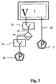
- Fig. 3 shows an embodiment of the device, which in comparison with Fig. 2 by a a further first closing device 12 and a further pump 18 which are connected to the separator 16 is connected, is expanded.
- the further vacuum pump 18 has the required vacuum for filtering manufactures and not the unprotected vacuum pump 2. So the vacuum pump 2 can Filters are switched off, which introduces the risk of damage to the pump Liquid reduced.
- the connection for the second line on the side of the is advantageous Vacuum chamber attached to make the pump more penetrating To protect liquids.
- Another advantage of this design is that the further Vacuum pump 18 the separator by an additional suction support Trapping and collecting the liquid there.
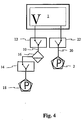
- FIG. 4 differs from the embodiment of FIG. 3 by a second closing device 22, which is between the vacuum pump 2 and the Vacuum chamber 1 is installed.
- the closing device can the vacuum pump 2 before protect the moisture that would otherwise get into the line 20 during filtering and Can destroy the pump.
- the check valve at the mouth of line 20 in the vacuum chamber be attached so that when the locking device is locked accumulated liquid can flow back into the vacuum chamber before the locking device, e.g. to dry, opens again.
- Fig. 5 differs from Fig. 4 on the one hand by a further second Locking device 24 and in that the vacuum pump 2 and the other Vacuum pump 18 are replaced by a vacuum pump 30.
- This can e.g. through a Line T-piece can be reached with the two lines 10 and 20 be merged to a common lower line 38 in the Vacuum pump to go.
- a vacuum pump in the device, which costs, weight, noise and Saves the complexity of the structure.
- the two locking devices 12 and 22 are a common first 3/2-way valve 32 summarized.
- the parts of the first and second Line 10 and 20, which is arranged between the closing device and the vacuum chamber are combined into a common upper line.
- the first 3/2-way valve 32 is designed so that either a connection from the vacuum chamber to the first Line 10 or a connection from the vacuum chamber to the second line 20 is made.
- Merging the two locking devices into a 3/2-way valve simplifies the construction since it is the number of lines and the number to be controlled Components in the system reduced. But it also has the advantage that liquid, which collects in a construction as in FIG. 5 on the locked closing device 22 and harmful to the vacuum pump when opening the closing device cannot accumulate here, as they get into the separator at any time during filtering can.
- Valves other than the 3/2-way valve are also suitable for use in the Pipe system conceivable at this point. But all of them must have those two switching states included with which the liquid and gases to be pumped either only in the Separator 16 or only get to pump 30.
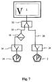
- Fig. 7 differs from Fig. 6 in that a pump 30 again by a vacuum pump 2 and another vacuum pump 18 is replaced.
- FIG. 8 is schematically identical to that in FIG. 1.
- the two locking devices 14 and 24 from FIG. 6 and FIG another 3/2-way valve 34 replaced with the same advantages as for the version of Fig. 7. It also enables the use of a single pump. alternative could in Figure 7, the two adjoining the locking devices Line sections combined by means of a T-piece and thus in a single pump be performed.
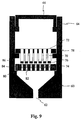
- FIG. 9 shows a preferred embodiment of a vacuum chamber 1 for treatment of liquids with hot plate with holes.
- a basic housing 60 is shown with a drain 62.
- An upper housing 64 is placed on the base housing, the Support surfaces between the base housing 60 and the upper housing 64 essentially seal gas-tight with each other.
- the lid 66 on the upper housing 64 closes also essentially gas-tight with the upper housing 64, so that the Total housing of the vacuum chamber 1 with basic housing 60, upper housing 64 and Cover 66 is essentially gas-tight except for the drain 62.
- a carrier plate 78 in the vacuum chamber 1 housed the containers 70 with inlet openings 72, filter bodies 76 and Exhaust openings 74 receives.
- the containers can preferably also reach up to the Filter bodies or protrude further into the holes in the heating plate. That way is a rapid drying of those adhering to the filter bodies 76 and outlet openings 74 Liquid residues guaranteed.
- the heating plate with holes enables e.g. on quick drying after washing with a washing solution such as ethanol.
- a fixed temperature can be set by the heating plate 80 to to support certain chemical processes in the containers in an advantageous manner.
- the heating plate 80 is replaced by a first heating tape 84 heated, the heating tape being advantageously guided around the heating plate.
- Another embodiment includes a second heating element 86 on the wall of FIG Vacuum chamber, which is preferably attached to the edge of the basic housing.
- a heating tape which is sunk in the wall. This too Heating element is preferably used to dry the vacuum chamber and enables one adjustable temperature for the substances in the vacuum chamber. Knocking off is advantageous by heating the walls of the vacuum chamber already evaporated ethanol avoided from the filter on the colder walls.
- the vacuum chamber 1 shown in FIG. 9 is also used for filtering.
- To cover 60 is removed and the carrier plate provided with containers in the upper Part of the upper housing 64 supports placed. A e.g. located there Seal ensures a gas-tight seal.
- the containers are above filter biological samples in liquid.
- the interior is exposed to a vacuum to the To allow liquid to flow through the filter body 76.
- the filter body 76 sucked liquid is drained by gravity and by vacuum pump suction 62 out from where it reaches the separator 16.
Landscapes
- Health & Medical Sciences (AREA)
- Chemical & Material Sciences (AREA)
- Analytical Chemistry (AREA)
- General Health & Medical Sciences (AREA)
- Hematology (AREA)
- Clinical Laboratory Science (AREA)
- Chemical Kinetics & Catalysis (AREA)
- Drying Of Solid Materials (AREA)
- Filtration Of Liquid (AREA)
- Degasification And Air Bubble Elimination (AREA)
- Electrical Discharge Machining, Electrochemical Machining, And Combined Machining (AREA)
- Processing And Handling Of Plastics And Other Materials For Molding In General (AREA)
Abstract
Description
Die Erfindung betrifft eine Unterdruckkammer zum automatisierten Filtern und Beseitigen von Flüssigkeiten und Flüssigkeitsresten.The invention relates to a vacuum chamber for automated filtering and removal of liquids and liquid residues.
In vielen Anwendungsgebieten der Technik, insbesondere in der Chemie, Biologie und beim Umweltschutz, ist es erforderlich, Flüssigkeiten zu analysieren, in ihre Bestandteile zu zerlegen oder in Reaktion mit anderen Substanzen zu bringen. Zu diesem Zweck werden Flüssigkeiten gefiltert, getrocknet, gewaschen, pipettiert und anderen Behandlungen unterworfen, wobei unter Flüssigkeit grundsätzlich jede Substanz, die in flüssiger Form vorliegt oder die sich in einer Flüssigkeit befindet, zu verstehen ist. Oft bestehen die Behandlungen aus einer langen Kette von Behandlungsabläufen, so daß es erforderlich ist, diese Prozeduren mit Hilfe von Robotern zu automatisieren.In many fields of application of technology, especially in chemistry, biology and in environmental protection, it is necessary to analyze liquids in their components to disassemble or react with other substances. To this end liquids are filtered, dried, washed, pipetted and others Subject to treatments, taking any substance contained in liquid in principle is in liquid form or is in a liquid. Often Treatments consist of a long chain of treatment processes, so it it is necessary to automate these procedures with the help of robots.
So ist beispielsweise bereits seit einigen Jahren das System "BioRobot 9600" des Anmelders auf dem Markt, mit dem molekularbiologische Verfahrensabläufe wie z.B. das Filtern, Waschen und Eluieren von Nukleinsäuren oder das Isolieren von RNA und/oder DNA automatisch durchgeführt werden. Für diese Abläufe werden als Filtermodul bezeichnete Trägerkörper eingesetzt, die eine Vielzahl von in Matrixform angeordneten Behältnissen aufweisen. Diese Behältnisse haben oben eine Einlaßöffnung und weisen im unteren Teil eine Auslaßöffnung auf. In den Behältnissen befinden sich weiterhin Filterkörper in Form von geeigneten Membranen oder Filtern, die zum Binden der zu analysierenden Substanzen in den Flüssigkeitsproben geeignet sind. For example, the "BioRobot 9600" system from the Applicant on the market with which molecular biological processes such as the Filtering, washing and eluting nucleic acids or isolating RNA and / or DNA can be done automatically. For these processes are used as a filter module designated support body used, which arranged a variety of arranged in matrix form Have containers. These containers have an inlet opening at the top and point in lower part on an outlet opening. In the containers are still Filter body in the form of suitable membranes or filters used to bind the analyzing substances in the liquid samples are suitable.
So werden zum Beispiel zur Erzeugung von hochreinen DNA-Plasmiden mittels einer Einzelpipetiervorrichtung zunächst Zellkulturen in Suspension gegeben, lysiert und anschließend mittels einer Pipetiervorrichtung in die Behältnisse der Trägerplatte gegeben. Anschließend werden die Trägerplatten mit den gefüllten Behältnissen so auf eine Unterdruckkammer aufgesetzt, daß die Auslaßöffnungen der Behältnisse in die Unterdruckkammer hineinragen. Durch das Anlegen eines Unterdrucks in der Unterdruckkammer werden die Flüssigkeiten in den Behältnissen durch die Filterkörper in die Unterdruckkammer gesaugt. In den Filterkörpern bleiben dabei die zu analysierenden Bestandteile nebst anderen Bestandteilen der Flüssigkeitsproben hängen. Um die interessierenden Bestandteile der Flüssigkeitsproben zu erhalten, müssen daher zunächst die nicht benötigten Substanzen aus den Filterkörpern herausgewaschen werden. Hierzu werden die Waschlösungen unterschiedlicher Konzentrationen in die Behältnisse pipettiert. Mittels dieser Waschlösungen wird ein Teil der nicht interessierenden Bestandteile der Flüssigkeitsproben von den Filterkörpern abgelöst. Anschließend werden mit Hilfe einer Eluitionslösung die interessierenden Bestandteile aus den Filterkörpern herausgelöst und aufgefangen.For example, to generate high-purity DNA plasmids a single pipetting device is first given cell cultures in suspension, lysed and then placed in the containers of the carrier plate by means of a pipetting device. Then the carrier plates with the filled containers are placed on one Vacuum chamber placed that the outlet openings of the containers in the Protrude into the vacuum chamber. By applying a vacuum in the Vacuum chamber, the liquids in the containers through the filter body the vacuum chamber sucked. The ones to be analyzed remain in the filter bodies Hang components along with other components of the liquid sample. To the To obtain components of the liquid samples of interest, you must first the substances not required are washed out of the filter bodies. For this the washing solutions of different concentrations are pipetted into the containers. By means of these washing solutions, part of the components of the Liquid samples detached from the filter bodies. Then using a Elution solution, the components of interest are removed from the filter bodies and collected.
Die in den einzelnen Schritten verwendeten Lösungen können jedoch die im folgenden Schritt verwendete Lösung kontaminieren. So können sich z.B. nach einem Waschschritt an den Auslaßöffnungen der Behältnisse aus Flüssigkeitsresten der Waschlösung Tropfen bilden, die vor dem folgenden Elutionsschritt zu entfernen sind. Dazu wurden früher die Trägerkörper bzw. Mikrotitrationsplatten von Hand mehrfach auf einer Unterlage mit saugfähigem Material fallengelassen, um diese Tropfen abzuschütteln. Wie in WO 98/53912 beschrieben, wurde das Entfernen der Restflüssigkeiten durch Anlegen eines Vakuums automatisiert.The solutions used in the individual steps can, however, the in Contaminate the solution used in the following step. For example, after one Washing step at the outlet openings of the containers from liquid residues Wash drops form drops to be removed before the next elution step. For this purpose, the carrier bodies or microtitration plates were previously opened several times by hand dropped on a pad of absorbent material to shake off these drops. As described in WO 98/53912, the removal of the residual liquids was carried out Automated creation of a vacuum.
In diesem Apparat fließen die durch die Filter gesaugten Flüssigkeiten, der Schwerkraft folgend, gewöhnlich zu einem Abscheider ab. Dort wird die Flüssigkeit gesammelt, so daß sie bei Bedarf wiederverwendet und/oder untersucht werden kann. Flüssigkeitsreste insbesondere im Filterkörperbereich oder an den Auslaßöffnungen der Behältnisse sind auf diese Weise jedoch nicht oder nur sehr langsam zu beseitigen. Der Trockenvorgang der Filterkörper und Auslaßöffnungen der Behältnisse dauert daher lang oder bleibt unvollständig. Es hat sich jedoch gezeigt, daß Flüssigkeitsreste weitgehendst beseitigt werden sollten, da sie die Reinheit der zu analysierenden Filterrückstände in den Behältnissen, die selber meist nur in kleinen Mengen vorhanden sind, beeinträchtigen und das chemische Verhalten verändern.The liquids drawn through the filters flow in this apparatus Following gravity, usually to a separator. There is the liquid collected so that it can be reused and / or examined if necessary. Liquid residues in particular in the filter body area or at the outlet openings of the However, containers cannot be removed in this way, or only very slowly. The The drying process of the filter body and outlet openings of the containers therefore takes a long time or remains incomplete. However, it has been shown that liquid residues are largely should be eliminated as they reduce the purity of the filter residues to be analyzed in the Containers, which are usually only present in small quantities, impair and change the chemical behavior.
Der Erfindung liegt daher die Aufgabe zugrunde, eine Unterdruckkammer bereitzustellen, die zum einen das Filtern von Flüssigkeiten bei Unterdruck und das Sammeln der gefilterten Flüssigkeiten ermöglicht, zum anderen aber auch das Beseitigen von Flüssigkeiten, insbesondere von Flüssigkeitsresten im Filterkörperbereich oder an den Auslaßöffnungen der Behältnisse möglichst vollständig und in kurzer Zeit durchführen kann, um damit die nach dem Stand der Technik bekannten Probleme zu vermeiden.The object of the invention is therefore to provide a vacuum chamber, the first is the filtering of liquids under negative pressure and the collection of the filtered liquids, but also the removal of Liquids, especially of liquid residues in the filter body area or on the Make the openings in the containers as complete as possible and in a short time can to avoid the problems known in the prior art.
Zur Lösung dieser Aufgabe wird eine Unterdruckkammer gemäß Patentanspruch 1
angegeben. Die Unterdruckkammer weist eine Heizplatte auf zur Erwärmung von
Bereichen der Unterdruckkammer. Bevorzugt ist die Heizplatte im Bodenbereich der
Unterdruckkammer angeordnet. Besonders bevorzugt weist die Heizplatte Löcher auf.
Vorzugsweise weist die erfindungsgemäße Unterdruckkammer eine Vakuumpumpe und
einen Abscheider auf, wobei die Unterdruckkammer mittels einer ersten Leitung mit dem
Abscheider verbunden und zwischen Unterdruckkammer und Abscheider eine erste
Schließvorrichtung angeordnet ist, und wobei die Unterdruckkammer mittels einer zweiten
Leitung mit der Vakuumpumpe verbunden ist, so daß die Unterdruckkammer unter
Umgehung des Abscheiders evakuiert werden kann.To solve this problem, a vacuum chamber according to
Es hat sich gezeigt, daß z.B. der Filterkörper durch seine Kapillarwirkung eine relativ große Menge an Flüssigkeit speichert, die durch das angelegte Vakuum nicht beseitigt wird. Durch Evakuieren der Unterdruckkammer unter Umgehung des Abscheiders können auch diese Flüssigkeiten beseitigt werden.It has been shown that e.g. the filter body due to its capillary action relatively large amount of liquid stores that are not due to the applied vacuum is eliminated. By evacuating the vacuum chamber bypassing the These liquids can also be removed from the separator.
Unter Flüssigkeiten ist dabei grundsätzlich jede Substanz zu verstehen, die in flüssiger Form vorliegt oder die sich in einer Flüssigkeit befindet. Insbesondere werden darunter chemische und/oder biologische Proben bzw. sich in Flüssigkeiten befindende chemische und/oder biologische Proben und die zur Behandlung chemischer und/oder biologischer Proben benötigte Substanzen gemeint.Liquids are basically understood to mean any substance that is in is in liquid form or is in a liquid. In particular including chemical and / or biological samples or liquids chemical and / or biological samples and those for the treatment of chemical and / or required biological samples.
Unter Behandlung von Flüssigkeiten in einer Unterdruckkammer sind verschiedene auf Flüssigkeiten und/oder Flüssigkeitsreste bezogene Tätigkeiten in einer Unterdruckkammer zu verstehen, wie z.B. eine Flüssigkeit durch einen Filter ziehen, Flüssigkeitsreste durch Abpumpen oder Verdampfen beseitigen, was bevorzugt auch als Trocknung der Unterdruckkammer bezeichnet werden kann, sowie Flüssigkeiten in einem Gefäß sammeln bzw. Flüssigkeiten einen Weg zu einem Abscheider freimachen.Treating liquids in a vacuum chamber are different activities related to liquids and / or liquid residues in one To understand the vacuum chamber, e.g. pull a liquid through a filter, Remove liquid residues by pumping or evaporation, which is also preferred as Drying of the vacuum chamber can be called, as well as liquids in one Collect the vessel or clear the way to a separator.
Unter Abscheider ist insbesondere eine Vorrichtung zu verstehen, die Flüssigkeiten auffangen und in einem Abscheidergefäß sammeln kann. Dabei kann das Abscheidegefäß bevorzugt groß genug sein, um einige 100 ml Flüssigkeit aufzunehmen. Das Auffangen wird z.B. dadurch erreicht, daß der Abscheider unterhalb einer zu sammelnden Flüssigkeit angeordnet ist, so daß die Flüssigkeit aufgrund der Schwerkraft in ein Abscheidergefäß fließt oder fällt; alternativ wird das Auffangen der Flüssigkeit auch durch Materialstrukturen erreicht, die dem Flüssigkeitsstrom, der z.B. durch eine Vakuumpumpe erzeugt ist, entgegenstehen, so daß sich die Flüssigkeiten an der Materialstruktur abscheiden und zum Abscheidergefäß fließen oder fallen. In einer bevorzugten Ausführung besteht der Abscheider aus einem geschlossenen Abscheidegefäß, das von oben kommend zwei Röhrchen aufweist, die in das Abscheidegefäß offen hineinragen. Das eine Röhrchen ist ein Zuflußrohr durch das die Flüssigkeiten durch Schwerkraft und/oder Sog durch eine Vakuumpumpe in das Abscheidegefäß transportiert und gesammelt werden; das andere Röhrchen ist das Ausgangsrohr, an das eine Vakuumpumpe angeschlossen ist. Das Ausgangsrohr endet über dem Flüssigkeitsspiegel, so daß die im Abscheidegefäß gesammelten Flüssigkeiten nicht zu der Vakuumpumpe gelangen können. Bevorzugt ist dabei die Öffnung des Ausgangsrohres oberhalb der Öffnung des Eingangsrohres angeordnet. Aber auch andere Verfahren zur Abscheidung von Flüssigkeiten können bevorzugt verwendet werden. Es können auch mehrere Abscheider in verschiedenen Anordnungen an die Unterdruckkammer oder an den Leitungen angebracht sein. A separator is to be understood in particular as a device, the liquids can collect and collect in a separator vessel. The separation vessel can preferably large enough to hold a few 100 ml of liquid. The catch e.g. thereby achieved that the separator below a liquid to be collected is arranged so that the liquid due to gravity in a separator vessel flows or falls; alternatively, the liquid is also collected by Material structures achieved that correspond to the liquid flow, e.g. by a vacuum pump is generated, oppose so that the liquids on the material structure separate and flow or fall to the separator vessel. In a preferred embodiment the separator consists of a closed separator vessel that comes from above has two tubes that openly protrude into the separation vessel. The one tube is an inflow pipe through which the liquids by gravity and / or suction through a Vacuum pump is transported into the separation vessel and collected; the other Tube is the outlet tube to which a vacuum pump is connected. The The outlet pipe ends above the liquid level, so that in the separation vessel collected liquids cannot reach the vacuum pump. Is preferred the opening of the outlet pipe above the opening of the inlet pipe arranged. However, other methods of separating liquids can also be used are preferably used. There can also be several separators in different Arrangements can be attached to the vacuum chamber or to the lines.
Die Evakuierung der Unterdruckkammer ohne Abscheider erfolgt durch eine (oder auch mehrere) Vakuumpumpen, die an die Unterdruckkammer angeschlossen sind, wobei der Abscheider von der Unterdruckkammer oder der Vakuumpumpe getrennt ist. Die Trennung wird zweckmäßig durch eine Schließvorrichtung, erreicht. Unter Schließvorrichtung ist z.B. eine Vorrichtung mit Eingang und Ausgang zu verstehen, die zwischen Durchlaß oder Sperrung umgeschaltet werden kann. Bevorzugte Schließvorrichtung ist z.B. ein vakuumtaugliches Sperrventil. Ist der Abscheider von der Unterdruckkammer so abgetrennt, daß es keine größeren mit der Unterdruckkammer in Verbindung stehende Flüssigkeitsreservoirs in der Unterdruckkammer gibt, so kann mit der Vakuumpumpe schnell ein hoher Unterdruck erreicht werden, der verbliebene Flüssigkeitsreste schneller zum Verdampfen bringt.The vacuum chamber without a separator is evacuated by a (or also several) vacuum pumps that are connected to the vacuum chamber, wherein the separator is separated from the vacuum chamber or the vacuum pump. The Separation is advantageously achieved by a locking device. Under Locking device is e.g. to understand a device with input and output that can be switched between passage or blocking. preferred Locking device is e.g. a vacuum-compatible shut-off valve. Is the separator from the Vacuum chamber separated so that there are no larger with the vacuum chamber in There are related liquid reservoirs in the vacuum chamber, so with the vacuum pump can quickly reach a high vacuum, the remaining one Liquid residue evaporates faster.
Mit der beschriebenen Vorrichtung können, wenn der Abscheider an die Unterdruckkammer angeschlossen ist, Flüssigkeiten in den Abscheider geleitet werden und, wenn der Abscheider von der Unterdruckkammer abgetrennt ist, die Unterdruckkammer und andere darin angeordneten Vorrichtungen von Flüssigkeitsresten befreit werden.With the device described, when the separator to the Vacuum chamber is connected, liquids are directed into the separator and, if the separator is separated from the vacuum chamber, the Vacuum chamber and other devices of liquid residues arranged therein be freed.
In einer weiteren Ausführungsform weist die Vorrichtung, die mit der erfindungsgemäßen Unterdruckkammer verwendet werden kann, eine erste Leitung auf, die die Unterdruckkammer über den Abscheider mit einer ersten Vakuumpumpe verbindet. Die Pumpe fördert das Transportieren der Flüssigkeiten in den Abscheider.In a further embodiment, the device having the vacuum chamber according to the invention can be used, a first line, which connects the vacuum chamber to a first vacuum pump via the separator. The pump promotes the transport of the liquids into the separator.
Vorteilhaft ist zwischen Abscheider und Unterdruckkammer und bevorzugt auch zwischen Abscheider und Vakuumpumpe eine Schließvorrichtung angeordnet, die wiederum z.B. ein vakuumtaugliches Sperrventil sein kann. Über die erste Leitung kann die Unterdruckkammer, unter Einbeziehung des Abscheiders, abgepumpt werden. Ist der Abscheider mit Flüssigkeit gefüllt, so verläuft der Evakuierungsprozeß langsam, da die im Abscheider liegende Flüssigkeit durch Verdampfen über lange Zeit Gas nachliefert. Solange die Flüssigkeit im Abscheider nicht vollständig verdampft ist, kann auch kein hoher Unterdruck erzielt werden. Durch die Schließvorrichtung wird dies vermieden. It is advantageous between the separator and the vacuum chamber and preferably also a closing device is arranged between the separator and the vacuum pump again e.g. can be a vacuum-compatible shut-off valve. Via the first line the vacuum chamber, including the separator, is pumped out. Is the The separator is filled with liquid, so the evacuation process runs slowly because the The liquid lying in the separator supplies gas by evaporation for a long time. As long as the liquid in the separator has not completely evaporated, neither can high negative pressure can be achieved. This is avoided by the locking device.
Gemäß einer weiteren Ausführungsform weist die Vorrichtung, die mit der erfindungsgemäßen Unterdruckkammer verwendet werden kann, eine zweite Leitung auf, die die Unterdruckkammer mit einer zweiten Vakuumpumpe verbindet. Da hier kein mit Flüssigkeit gefüllter Abscheider in der Leitung angebracht ist, können bei gleicher Pumpleistung mit dieser Leitung die Unterdruckkammer schnell evakuiert und die Flüssigkeitsreste schnell beseitigt werden, vorrausgesetzt, daß der Abscheider durch die Schließvorrichtung von der Unterdruckkammer getrennt ist. Bevorzugt hat auch die zweite Leitung mindestens eine Schließvorrichtung, die dafür sorgt, daß im Filterungsprozeß keine Flüssigkeit von der Unterdruckkammer in die Vakuumpumpe gelangt.According to a further embodiment, the device which is connected to the vacuum chamber according to the invention can be used, a second line, which connects the vacuum chamber to a second vacuum pump. Since no one here Liquid-filled separators installed in the line can be used for the same Pumping power with this line quickly evacuated the vacuum chamber and the Liquid residues are removed quickly, provided that the separator through the Locking device is separated from the vacuum chamber. The second also preferred Line at least one locking device that ensures that in the filtering process no liquid gets into the vacuum pump from the vacuum chamber.
Bevorzugt wird für die Vorrichtung anstatt zweier Vakuumpumpen nur eine Vakuumpumpe eingesetzt, um Kosten und Gewicht zu sparen. Die erste Leitung zwischen Abscheider und Vakuumpumpe und die zweite Leitung werden dabei bevorzugt durch ein Leitungs T-Stück zu einer Leitung zusammengelegt, bevor sie in den Ansaugstutzen der Vakuumpumpe münden. Bevorzugt werden auch die erste Leitung zwischen Abscheider und Unterdruckkammer und zweite Leitung, ebenfalls durch ein Leitungs T-Stück, zusammengelegt, um mit einer Leitung in die Unterdruckkammer zu münden.Instead of two vacuum pumps, only one is preferred for the device Vacuum pump used to save costs and weight. The first line between Separators and vacuum pumps and the second line are preferred by a Line T-piece folded into a line before it in the intake of the Vacuum pump open. The first line between separators is also preferred and vacuum chamber and second line, also through a line T-piece, folded to open with a line in the vacuum chamber.
Bevorzugt werden die erste und zweite Schließvorrichtung durch ein 3/2-Wege-Ventil ersetzt, um die Anzahl der anzusteuernden aktiven Komponenten zu reduzieren. Das 3/2-Wege-Ventil ist dabei so in das Leitungssystem eingebaut, daß der Eingang des 3/2-Wege-Ventils mit der Unterdruckkammer verbunden ist, während der erste der zwei Ausgänge des 3/2-Wege-Ventils zum Abscheider und der zweite Ausgang direkt zur Vakuumpumpe führt. Vorteilhaft ersetzt das 3/2-Wege-Ventil zwei Anschlüsse an die Unterdruckkammer bzw. das erste Leitungs T-Stück. Das 3/2-Wege-Ventil läßt sich in zwei Schalterpositionen schalten, wobei es in der ersten Schalterposition den Eingang mit dem ersten Ausgang verbindet und dabei den zweiten Ausgang versperrt, während es in der zweiten Schalterposition den Eingang mit dem zweiten Ausgang verbindet und den ersten Ausgang versperrt.The first and second closing devices are preferred by a 3/2-way valve replaced to reduce the number of active components to be controlled. The 3/2-way valve is built into the piping system so that the inlet of the 3/2-way valve connected to the vacuum chamber while the first of the two Outputs of the 3/2-way valve to the separator and the second output directly to Vacuum pump leads. The 3/2-way valve advantageously replaces two connections to the Vacuum chamber or the first line T-piece. The 3/2-way valve can be in switch two switch positions, being in the first switch position with the input connects the first exit, blocking the second exit while it is in the second switch position connects the input to the second output and the first exit blocked.
In einer weiteren Ausgestaltung der Erfindung werden vorteilhaft die weitere erste und weitere zweite Schließvorrichtung durch ein weiteres 3/2-Wege-Ventil ersetzt, um die Anzahl der anzusteuernden aktiven Komponenten zu reduzieren. Das weitere 3/2-Wege-Ventil ist dabei bevorzugt so in das Leitungssystem eingebaut, daß der Eingang des weiteren 3/2-Wege-Ventils mit der Vakuumpumpe verbunden ist, während der erste der zwei Ausgänge des weiteren 3/2-Wege-Ventils zum Abscheider und der zweite Ausgang am Abscheider vorbei zur Unterdruckkammer führt. Dies erlaubt die Verwendung einer Vakuumpumpe. Vorteilhaft ersetzt das weitere 3/2-Wege-Ventil auch das zweite Leitungs T-Stück. Das 3/2-Wege-Ventil läßt sich bevorzugt in zwei Schalterpositionen schalten, wobei es in der ersten Schalterposition den Eingang mit dem ersten Ausgang verbindet und dabei den zweiten Ausgang versperrt und in der zweiten Schalterposition den Eingang mit dem zweiten Ausgang verbindet und den ersten Ausgang versperrt.In a further embodiment of the invention, the further first are advantageous and another second closing device replaced by another 3/2-way valve to the To reduce the number of active components to be controlled. The further 3/2-way valve is preferably installed in the line system so that the input of the Another 3/2-way valve is connected to the vacuum pump, while the first one two outputs of the further 3/2-way valve to the separator and the second output leads past the separator to the vacuum chamber. This allows the use of a Vacuum pump. The further 3/2-way valve also advantageously replaces the second line Tee. The 3/2-way valve can preferably be switched to two switch positions, in the first switch position it connects the input to the first output and the second output blocked and the input in the second switch position connects the second output and blocks the first output.
In einer bevorzugten Ausführung ist die erfindungsgemäße Unterdruckkammer Bestandteil einer Vorrichtung zum Filtern von Flüssigkeiten. Das Vakuum in der Unterdruckkammer dient bevorzugt dazu, Flüssigkeiten, die in Behältnissen mit Filterkörpern in die Einlaßöffnungen eingegeben worden sind, durch die Filterkörper zu saugen. Die Unterdruckkammer ist für diesen Zweck bevorzugt so eingerichtet, daß sie eine Öffnung nach oben hat, in die ein oder mehrere dieser Behältnisse mit zu filternden Flüssigkeiten in die Unterdruckkammer eingelassen werden können. Die obere Öffnung der Unterdruckkammer und die Behältnisse sind so eingerichtet, daß Behältnis und obere Öffnung gasdicht miteinander abschließen. Solange Flüssigkeit oberhalb der Filterkörper im Behältnis steht, ist die Unterdruckkammer also weiterhin gasdicht abgeschlossen, so daß eine Vakuumpumpe einen Unterdruck in der Unterdruckkammer erzeugen kann. Dieser Unterdruck saugt die in den Behältnissen untergebrachten Flüssigkeiten durch die Filterköper, so daß ein schnelles Filtern ermöglicht ist. Erst wenn die Flüssigkeit in den Behältnissen vollständig durch die Filter gesaugt worden ist und die Filterung somit beendet ist, kann atmosphärische Luft durch die Filter in die Unterdruckkammer geraten.In a preferred embodiment, the vacuum chamber according to the invention Part of a device for filtering liquids. The vacuum in the Vacuum chamber is preferably used to hold liquids in containers Filter bodies have been entered into the inlet openings through the filter bodies suck. The vacuum chamber is preferably set up for this purpose so that it has an opening at the top into which one or more of these containers are to be filtered Liquids can be let into the vacuum chamber. The top opening the vacuum chamber and the containers are set up so that the container and upper Seal the opening in a gas-tight manner. As long as liquid above the filter body is in the container, the vacuum chamber is still sealed gas-tight, so that a vacuum pump can create a vacuum in the vacuum chamber. This negative pressure sucks the liquids accommodated in the containers through the Filter body, so that a quick filtering is possible. Only when the liquid in the Containers have been completely sucked through the filter and thus the filtering atmospheric air can get through the filters into the vacuum chamber.
Filtern ist hier in einem weiteren Sinne zu verstehen: es meint das Saugen von Flüssigkeiten in benannten Behältnissen durch die Filterkörper mit Hilfe eines Unterdrucks, wobei dieser Vorgang auch beim Waschen von Filterrückständen mit einer Lösung, insbesondere mit Ethanol, oder beim Eluieren von Filterrückständen mit einer Elutionslösung abläuft. Filtering is to be understood in a broader sense here: it means sucking Liquids in named containers through the filter body using a Vacuum, this process also when washing filter residues with a Solution, especially with ethanol, or when eluting filter residues with a Elution solution expires.
Beim Filtern werden die Schließvorrichtungen, insbesondere die Sperrventile und/oder die 3/2-Wege-Ventile der Leitungen bevorzugt so geschaltet, daß der Abscheider an die Unterdruckkammer angeschlossen ist und die Unterdruckkammer mit Abscheider evakuiert wird. Die durch die Filterkörper gesogene Flüssigkeit fließt so, durch Schwerkraft oder durch Pumpsog angetrieben, zum Abscheider. Dabei muß darauf geachtet werden, daß keine Flüssigkeit durch Sog oder Schwerkraft in die Vakuumpumpe gerät. Um das zu verhindern, wird entweder bevorzugt durch den Abscheider gepumpt, so daß die Flüssigkeit dort abgefangen wird, oder der Einlaß des Pumpstutzen in der Unterdruckkammer befindet sich an einem Ort, zu dem die Flüssigkeiten trotz Pumpsog nicht gelangen können. Dabei werden die beiden 3/2-Wege-Ventile bevorzugt beide in die erste Schalterposition geschaltet, so daß mit dem Abscheider evakuiert wird.When filtering, the closing devices, especially the check valves and / or the 3/2-way valves of the lines are preferably switched so that the separator is connected to the vacuum chamber and the vacuum chamber with separator is evacuated. The liquid sucked through the filter body flows through Gravity or pump suction, to the separator. It has to be done Care should be taken to ensure that no liquid is drawn into the vacuum pump by suction or gravity device. To prevent this, it is preferred to pump through the separator, see above that the liquid is trapped there, or the inlet of the pump nozzle in the Vacuum chamber is located at a location to which the liquids despite pump suction cannot get. The two 3/2-way valves are preferably both in the first switch position switched so that evacuation is carried out with the separator.
Gemäß eines weiteren Aspekts der Erfindung können Flüssigkeiten beseitigt werden, insbesondere Flüssigkeitsreste, die beim Filtern nicht in den Abscheider abgeflossen sind, sondern in den Filterkörpern oder an den Auslässen der Behältnisse als Tropfen hängengeblieben sind oder an den Oberflächen innerhalb der Unterdruckkammer zurückgeblieben sind. Da diese Flüssigkeitsreste, insbesondere in den Filterkörpern, eine Analyse verfälschen können, sind diese auf ein Minimum zu reduzieren. Bevorzugt wird mit Hilfe eines Unterdrucks durch eine an die Unterdruckkammer angeschlossene Vakuumpumpe die Siedetemperatur der Flüssigkeit gesenkt, so daß die Flüssigkeit beschleunigt vergast. Um den Unterdruck zu maximieren wird bevorzugt ein Deckel auf die Unterdruckkammer aufgebracht, der die obere Öffnung der Unterdruckkammer gasdicht abschließt, da sonst die Kammer offen wäre. Das Gas wird durch die Vakuumpumpe abgesaugt.According to another aspect of the invention, liquids can be eliminated be, especially liquid residues that do not get into the separator when filtering have flowed out, but in the filter bodies or at the outlets of the containers Drops are stuck or on the surfaces inside the vacuum chamber are left behind. Since these liquid residues, especially in the filter bodies, a Falsify analysis, these must be reduced to a minimum. Is preferred with the help of a vacuum through a connected to the vacuum chamber Vacuum pump lowers the boiling point of the liquid so that the liquid accelerated gasification. In order to maximize the negative pressure, a lid is preferred the vacuum chamber applied to the top opening of the vacuum chamber gas-tight, otherwise the chamber would be open. The gas is through the Vacuum pump sucked off.
Weiterhin erfolgt bevorzugt die Beseitigung von Flüssigkeiten dadurch, daß Schließvorrichtungen und Ventile den Abscheider von der Unterdruckkammer abtrennen und eine Vakuumpumpe, die nicht mit einem Abscheider verbunden ist, die Unterdruckkammer evakuiert. Da auf diese Weise der Abscheider nicht immer neues Gas durch verdampfende Flüssigkeit in die Unterdruckkammer nachliefern kann, kann der Unterdruck in der Kammer erhöht und damit die Siedetemperatur der Flüssigkeitsreste weiter gesenkt werden. Auf diese Weise erfolgt die Verdampfung der Restflüssigkeit schneller und rückstandsloser. Eine rückstandslose Beseitigung der Restflüssigkeiten ist insbesondere erforderlich in den Behältnissen und Filterkörpern, da sich hier oft kleine Mengen von zu analysierenden Substanzen befinden, die durch Restflüssigkeiten verunreinigt werden würden und daher falsche Resultate liefern würden. Dabei werden für die Beseitigung der Flüssigkeiten die beiden 3/2-Wege-Ventile in die zweite Schalterposition geschaltet, so daß ohne Abscheider evakuiert wird.Furthermore, the removal of liquids preferably takes place in that Closing devices and valves separate the separator from the vacuum chamber and a vacuum pump that is not connected to a separator Vacuum chamber evacuated. Because in this way the separator is not always new gas can deliver through evaporating liquid into the vacuum chamber, the Vacuum in the chamber increases and thus the boiling point of the liquid residue be further reduced. In this way, the residual liquid is evaporated faster and less residue. A residue-free removal of the residual liquids is especially necessary in the containers and filter bodies, since there are often small ones Amounts of substances to be analyzed are located by residual liquids would be contaminated and therefore would give false results. Doing so for the elimination of liquids the two 3/2-way valves in the second Switch position switched so that evacuation is carried out without a separator.
Gemäß einer weiteren Ausführungsform ist vorteilhaft an die Unterdruckkammer oder an einer anderen geeigneten Stelle ein Belüftungsventil angeschlossen, so daß die Unterdruckkammer belüftet werden kann. Die Belüftung erfolgt z.B. nach einem Schritt zur Beseitigung von Flüssigkeiten, da für eine Beseitigung von Flüssigkeiten ein mehrfacher Zyklus von Abpumpen und Belüften sich als vorteilhaft herausgestellt hat. Zweckmäßigerweise ist zwischen Belüftungsventil und Unterdruckkammer ein Drosselventil angebracht, mit dem beim Belüften ein zu schneller Druckanstieg, der die Unterdruckkammer oder die Flüssigkeiten in der Unterdruckkammer beschädigen oder durcheinander bringen würde, vermieden werden kann. Bevorzugt ist an die Unterdruckkammer oder an eine der Leitungen ein Drucksensor angebracht, mit dessen Hilfe der Druck in der Unterdruckkammer überwacht werden kann.According to a further embodiment, the vacuum chamber is advantageous or connected at another suitable place a ventilation valve, so that the Vacuum chamber can be ventilated. The ventilation takes place e.g. after one step for liquid removal, as for liquid removal multiple cycle of pumping and aeration has proven to be advantageous. It is expedient to have a between the ventilation valve and the vacuum chamber Throttle valve attached, with which a too rapid pressure increase during ventilation, which the Damage the vacuum chamber or the liquids in the vacuum chamber or confused, can be avoided. Is preferred to the Vacuum chamber or a pressure sensor attached to one of the lines, with its Help the pressure in the vacuum chamber can be monitored.
Bevorzugt umfaßt die Vorrichtung eine zentrale Steuerung für Schließvorrichtungen und Sperrventile, 3/2-Wege-Ventile, Belüftungsventil und/oder Vakuumpumpen. Mit dieser Steuerung kann die Vorrichtung überwacht und bequem gesteuert werden. Insbesondere können Abläufe wie Filtern, Beseitigung von Flüssigkeit und Belüften automatisiert, reproduzierbar wiederholt und damit leichter optimiert werden. Auch Fehlbedienungen kommen bei einem vollautomatischen Ablauf kaum noch vor.The device preferably comprises a central control for Closing devices and check valves, 3/2-way valves, ventilation valve and / or Vacuum pumps. With this control, the device can be monitored and convenient to be controlled. In particular, processes such as filtering, liquid removal and ventilation automated, reproducibly repeated and thus easier to optimize. Incorrect operations are also rarely used in a fully automatic process.
Bevorzugt kann die Unterdruckkammer Behältnisse aufnehmen, mit denen Filterungen durchgeführt werden können: Bevorzugt haben die Behältnisse eine Einlaßöffnung, Filterkörper und eine Auslaßöffnung, so daß in die Einlaßöffnung eingegebene Flüssigkeiten mittels Schwerkraft oder Unterdrucksog durch den Filter zur Auslaßöffnung gelangen können. Bevorzugt sind diese Behältnisse in einer matrixartigen Struktur auf einer Trägerplatte angebracht, so daß bevorzugt mehrfache Filterungen parallel durchgeführt werden können. Die Löcher der Heizplatte sind dabei bevorzugt so ausgeformt, daß die Behältnisse mit einem unteren Teilbereich in die Löcher hineinragen können. Die Heizplatte mit den Löchern erwärmt dadurch bevorzugt die Behältnisse am Filterkörperbereich und am Auslaßbereich und trägt so zu einer beschleunigten Beseitigung von Flüssigkeitsresten im Filterbereich und Auslaßbereich bei. Auf diese Weise können die in den Filterkörpern angelagerten chemischen und/oder biologischen Substanzen, insbesondere die Nukleinsäuren, schnell und in großer Reinheit isoliert werden. Bevorzugt kann die Heizplatte auch zu einer Steuerung der Temperatur an den zu analysierenden Flüssigkeiten in den Behältnissen beitragen. Außerdem wird das Aufspritzen von Flüssigkeit auf die obere Fläche der Heizplatte vermieden sowie die Möglichkeiten von Kreuzkontaminationen reduziert.The vacuum chamber can preferably hold containers with which Filtering can be carried out: The containers preferably have a Inlet opening, filter body and an outlet opening so that in the inlet opening Liquids entered by gravity or vacuum suction through the filter Outlet opening can reach. These containers are preferably in a matrix Structure attached to a support plate, so that preferably multiple filtering can be carried out in parallel. The holes in the heating plate are preferably so formed that the containers protrude into the holes with a lower portion can. The heating plate with the holes thereby preferably heats the containers Filter body area and at the outlet area and thus contributes to an accelerated Removal of liquid residues in the filter area and outlet area. To this In this way, the chemical and / or biological deposits in the filter bodies Substances, especially the nucleic acids, isolated quickly and in great purity become. The heating plate can preferably also be used to control the temperature analyzing liquids in the containers. Besides, that will Avoid splashing of liquid on the top surface of the heating plate as well as the Cross-contamination possibilities reduced.
Bevorzugt wird die Heizplatte durch ein Heizband, das im äußeren Bereich der Heizplatte angebracht ist, erwärmt. In einer bevorzugten Ausführung ist das Heizband um die Heizplatte herumgeführt. Bevorzugt ist die Heizplatte aus einem wärmeleitenden Material, so daß die Temperatur weitestgehend gleichmäßig über die gesamte Fläche verteilt ist.The heating plate is preferred by a heating tape which is in the outer region of the Heating plate is attached, heated. In a preferred embodiment, the heating tape is around led the heating plate around. The heating plate is preferably made of a thermally conductive one Material so that the temperature is largely uniform over the entire area is distributed.
Gemäß einer weiteren Ausgestaltung weist die Unterdruckkammer im Bereich der Seitenwände zumindest ein Heizungselement auf. Das Heizungselement dient dazu bei Bedarf die Seitenwände zu erwärmen, was vorteilhaft die Kondensation Flüssigkeiten und Flüssigkeitsresten an den im Verhältnis zur Heizplatte und Filterkörpern kälteren Seitenwänden verhindert. Auch zur Erwärmung der Flüssigkeiten in den Behältnissen kann das Heizelement bevorzugt dienen. Bevorzugt ist das Heizungselement ein Heizband, was bevorzugt in der Unterdruckkammerinnenwand angebracht ist.According to a further embodiment, the vacuum chamber has in the area of the Side walls at least one heating element. The heating element serves this purpose Need to heat the side walls, which is beneficial to the condensation liquids and Liquid residues on the colder ones in relation to the heating plate and filter bodies Side walls prevented. Also for heating the liquids in the containers the heating element can preferably serve. The heating element is preferably a Heating tape, which is preferably attached in the vacuum chamber inner wall.
Bevorzugt ist in der Unterdruckkammer mindestens ein Temperatursensor angebracht, mit dem die Temperatur in der Unterdruckkammer abgelesen werden kann. Bevorzugt steuert eine elektronische Einheit die Temperatur an der Heizungsplatte und/oder der Heizungselemente, was für eine schonende Behandlung der Flüssigkeiten und einen schnellstmöglichen Trockenvorgang vorteilhaft ist. Die elektronsiche Steuerung der Heizplatte und/oder Heizungselement ist weiterhin nützlich für einen automatisierten Ablauf von Heizungszyklen. At least one temperature sensor is preferred in the vacuum chamber attached, with which the temperature in the vacuum chamber can be read. An electronic unit preferably controls the temperature on the heating plate and / or the heating elements, what a gentle treatment of the liquids and a quickest possible drying process is advantageous. The electronic control the heating plate and / or heating element is still useful for an automated Sequence of heating cycles.
Mit der erfindungsgemäßen Unterdruckkammer kann ein Verfahren zur Beseitigung von
Flüssigkeiten mit den folgenden Schritten durchgeführt werden:
Bevorzugt wird die Unterdruckkammer luftdicht abgeschlossen, um einen möglichst guten Unterdruck zu erreichen, was die Beseitigung der Flüssigkeitsreste deutlich beschleunigt. Bevorzugt wird das Verfahren angewendet, um die Filter mit den zu analysierenden Filterrückständen zu trocknen, d.h. wenn die Behältnisse innerhalb der Unterdruckkammer angeordnet sind. Um die Unterdruckkammer mit den darin angeordneten Behältnissen gasdicht abzuschließen, wird bevorzugt ein Deckel, der die Behältnisse überdeckt und gasdicht mit der Öffnung in der Unterdruckkammer abschließt, auf die Unterdruckkammer gesetzt.The vacuum chamber is preferably sealed airtight in order to be as possible to achieve good negative pressure, which clearly eliminates the liquid residues accelerated. The method is preferably used to filter the filter drying filter residues, i.e. if the containers within the Vacuum chamber are arranged. To the vacuum chamber with the inside to arrange arranged containers gastight, a lid is preferred, which the Containers covered and sealed gas-tight with the opening in the vacuum chamber, placed on the vacuum chamber.
Bevorzugt wird die Unterdruckkammer mit einer Vakuumpumpe verbunden und der Abscheider wird von der Unterdruckkammer und Vakuumpumpe abgetrennt. Bevorzugt wird dann die Vakuumpumpe eingeschaltet. Die Abwesenheit des Abscheiders von der zu evakuierenden Unterdruckkammer verbessert das Vakuum, da keine verdampfende Flüssigkeit aus dem Abscheider in die zu evakuierende Unterdruckkammer treten kann. Damit erhöht sich deutlich die Geschwindigkeit, mit der die zu beseitigenden Flüssigkeiten verdampfen und abgepumpt werden können.The vacuum chamber is preferably connected to a vacuum pump and the The separator is separated from the vacuum chamber and vacuum pump. Prefers the vacuum pump is then switched on. The absence of the separator from the to evacuating vacuum chamber improves the vacuum since there is no evaporating Liquid from the separator can enter the vacuum chamber to be evacuated. This significantly increases the speed at which the liquids to be removed are removed evaporate and can be pumped out.
Bevorzugt wird nach einer Zeit des Abpumpens die Unterdruckkammer belüftet. Dieser Schritt wird bevorzugt dann ausgeführt, wenn die Beseitigung der Flüssigkeiten durch einen mehrfach zu wiederholenden Zyklus aus Abpumpen und Belüften beschleunigt werden soll.The vacuum chamber is preferably vented after a period of pumping. This step is preferably carried out when removing the liquids accelerated by a repeated cycle of pumping and aeration shall be.
Bevorzugt wird in dem Verfahren Ethanol beseitigt, das eine bevorzugte Waschlösung für Nukleinsäuren und die Isolierung von Flüssigkeiten mit DNA oder RNA darstellt. The process preferably removes ethanol, which is a preferred washing solution for nucleic acids and the isolation of liquids with DNA or RNA.
Bevorzugt wird zur Beseitigung der Flüssigkeiten die Unterdruckkammer durch Heizelemente oder die Heizplatte erwärmt, um die Verdampfung zu beschleunigen. Bevorzugt wird auf eine Temperatur oberhalb des Siedepunkts geheizt, was zur schnellstmöglichen Beseitigung der Flüssigkeiten führt. Da der Siedepunkt einer Flüssigkeit mit steigenden Unterdruck fällt, ermöglicht ein gutes Vakuum ein Sieden schon bei niedrigen Temperaturen.The vacuum chamber is preferably used to remove the liquids Heating elements or the heating plate heated to accelerate the evaporation. It is preferably heated to a temperature above the boiling point, which leads to leads to the fastest possible removal of liquids. Since the boiling point is one If liquid falls with increasing negative pressure, a good vacuum already allows boiling at low temperatures.
Bevorzugt wird das Verfahren durch eine elektronische Einheit gesteuert, da dadurch die Temperatur in der Unterdurckkammer, die Zeitdauern des Pumpens und Zeitpunkte des Belüftens sowie die einzustellenden Heiztemperaturen in der Unterdruckkammer optimal und reproduzierbar geregelt und automatiseirt werden kann.The method is preferably controlled by an electronic unit, as a result of this the temperature in the lower pressure chamber, the pumping times and times of the Ventilation and the heating temperatures to be set in the vacuum chamber are optimal can be regulated and reproducibly and automated.
In den Zeichnungen sind Ausführungsbeispiele der Erfindungen dargestellt.
Es zeigen:
- Fig. 1
- Aufbau einer Vorrichtung zur Behandlung von Flüssigkeiten in der erfindungsgemäßen Unterdruckkammer, insbesondere zur Filterung und Beseitigung von Flüssigkeiten in der Unterdruckkammer mit elektronischer Steuerung;
- Fig.2 - Fig. 8
- Weitere Ausführungen der Vorrichtung zur Behandlung von Flüssigkeiten in der erfindungsgemäßen Unterdruckkammer, insbesondere zur Filterung und Beseitigung von Flüssigkeiten in der Unterdruckkammer;
- Fig.9
- Eine bevorzugte Ausführung einer Unterdruckkammer zur Behandlung von Flüssigkeiten, insbesondere zur Filterung, Waschen und Trocknung von Flüssigkeitsproben
Show it:
- Fig. 1
- Construction of a device for treating liquids in the vacuum chamber according to the invention, in particular for filtering and removing liquids in the vacuum chamber with electronic control;
- Fig. 2-8
- Further designs of the device for treating liquids in the vacuum chamber according to the invention, in particular for filtering and removing liquids in the vacuum chamber;
- Figure 9
- A preferred embodiment of a vacuum chamber for the treatment of liquids, in particular for filtering, washing and drying liquid samples
Fig. 1 zeigt schematisch eine Ausführung einer Vorrichtung zur Behandlung von
Flüssigkeiten in einer Unterdruckkammer, insbesondere zur Filterung und Beseitigung von
Flüssigkeiten. Die wesentlichen Elemente sind die Unterdruckkammer 1, der Abscheider
16 , die Vakuumpumpe 30 sowie das 3/2-Wege-Ventil 32 und das weitere 3/2-Wege-Ventil
34. Sind beide 3/2-Wege-Ventile in die erste Schalterposition geschaltet, so ist die
Vakuumpumpe 30 ausschließlich über den Abscheider 16 mit der Unterdruckkammer
verbunden. Sind beide 3/2-Wege-Ventile in die zweite Schalterposition geschaltet, so ist
die Vakuumpumpe 30 ausschließlich unter Umgehung des Abscheiders mit der
Unterdruckkammer verbunden.Fig. 1 shows schematically an embodiment of a device for the treatment of
Liquids in a vacuum chamber, especially for filtering and removing
Liquids. The essential elements are the
Weitere Elemente der gezeigten Ausführung sind eine Belüftungsleitung 39 mit einem
Belüftungsventil 40 und bevorzugt einem Drosselventil 42 zwischen Belüftungsventil 40
und Unterdruckkammer 1. Mit dem Drosselventil kann z.B. die Geschwindigkeit, mit der
die Belüftung der Unterdruckkammer vor sich gehen soll, eingestellt werden. In der
gezeigten Ausführung ist weiterhin ein Drucksensor 44 gezeigt, der an die
Belüftungsleitung angeschlossen ist. Mit dem Drucksensor 44 wird der in der
Unterdruckkammer herrschende Druck gemessen und überwacht. Grundsätzlich ist es
nicht wesentlich wie lang die Belüftungsleitung ist und wo sie in die Unterdruckkammer
einmündet. Mit einem geeigneten Aufbau kann möglicherweise auch ganz auf eine
Belüftungsleitung verzichtet werden, wenn es gelingt, Belüftungsventil und/oder
Drosselventil und/oder Drucksensor direkt an das Unterdruckgehäuse anzubringen.
Entscheidend ist, daß das Belüftungsventil die Unterdruckkammer belüften kann und
bevorzugt der Druck in der Unterdruckkammer mit Hilfe des Drucksensors gemessen
werden kann.Further elements of the embodiment shown are a
Weiterhin sind hinter der Vakuumpumpe 30 ein weiterer Abscheider 48 und ein
Geräuschdämpfer 50 gezeigt. Der weitere Abscheider 48 hat die Funktion, die durch die
Pumpe abgegebenen Luft von Feuchtigkeit zu befreien und ggf. die durch die
Vakuumpumpe nach hinten abgegebene Luft zu filtern. Furthermore, there is another
Schließlich ist die elektronische Regelung 46 gezeigt, die die aktiven Komponenten des
Systems, vor allem 3/2-wege-Ventile, Belüftungsventil, Pumpe und Drucksensor, liest
und/oder regelt. Die elektronische Regelung 46 ist jedoch nicht nur auf die gezeigten
Komponenten begrenzt; so können mit der Steuereinheit auch die Temperatur in der
Unterdruckkammer geregelt oder das Abheben und Aufsetzen des Deckels 66 auf die
Unterdruckkammer veranlaßt werden. Mit der elektronischen Steuerung kann so der
Flüssigkeitsbehandlungsablauf, also z.B. eine hintereinander verlaufende Filter- oder
Trockenprozedur, automatisiert und optimiert werden. Dies ist nicht nur ein Zeitgewinn,
sondern ermöglicht größtmögliche Reproduzierbarkeit und Fehlerfreiheit bezüglich der
Bedienung.Finally, the
Fig. 1 zeigt eine Ausführung der Vorrichtung zum Behandeln von Flüssigkeiten in
einer Unterdruckkammer. Durch Schalten der beiden 3/2-Wege-Ventile auf die erste
Schalterposition kann man in der Unterdruckkammer 1 einen Unterdruck erzeugen, der
z.B. zum Filtern benutzt wird, und die Flüssigkeit zum Abscheider 16 führen.Fig. 1 shows an embodiment of the device for treating liquids in
a vacuum chamber. By switching the two 3/2-way valves to the first
Switch position can create a vacuum in the
Sind beide 3/2-Wege-Ventile in Fig.1 in die zweite Schalterposition geschaltet, so
können keine größeren Flüssigkeitsmengen aufgenommen werden, da die Flüssigkeiten
dann leicht zur Vakuumpumpe 30 gelangen und die Vakuumpumpe 30 beschädigen
können. Diese Schalterposition ist jedoch für die Beseitigung von Flüssigkeitsresten oder
Trocknung der Unterdruckkammer 1 vorgesehen. In dieser Schalterposition ist der
Abscheider 16 von der Unterdruckkammer abgetrennt, was das Evakuieren deutlich
erleichtert, da vom Abscheider 16 keine verdampfte Flüssigkeit in die Unterdruckkammer
1 mehr gelangen kann. Weiterhin ist (wie in Figur 9 gezeigt) in einer bevorzugten
Ausführung in dieser Schalterposition der Deckel 66 auf das Unterdruckgehäuse gasdicht
aufgesetzt, so daß die Unterdruckkammer, bis auf den Abfluß 62, gasdicht abgedichtet ist.
In der beschriebenen Ausführung kann der Druck so z.B. auf etwa 30 mbar reduziert
werden, was etwa eine Größenordnung besser ist als wenn man mit angeschlossenem
Abscheider evakuiert. Durch den so reduzierten Druck sinkt der Siedepunkt von
Flüssigkeiten, so daß die z.B. von einer Filterung verbliebenen Flüssigkeitsreste an den
Filterkörpern 76 der Behältnisse 70 oder an anderen Oberflächen in der
Unterdruckkammer deutlich schneller verdampfen und durch die Vakuumpumpe 30
abgepumpt werden können. Die bessere Trocknung führt direkt zu besseren Resultaten,
wenn es z.B. darum geht, Filterrückstände in möglichst reiner Form zu erhalten: z. B.
gelingt es, durch die rückstandslosere Beseitigung der Waschlösung Ethanol im
Waschprozeß zur Isolierung von Nukleinsäuren eluierte Nukleinsäuren mit einem
Restethanolanteil von weniger als 0.5% zu erhalten.If both 3/2-way valves in Fig. 1 are switched to the second switch position, so
large amounts of liquid cannot be absorbed because the liquids
then easily get to the
Fig. 1 ist eine Ausführung der Vorrichtung. Weitere Ausführungen sind in den Figuren
2 bis 8 gezeigt. Fig. 2 zeigt eine Ausführung eines minimalen Aufbaus, mit dem sowohl
bei Unterdruck gefiltert als auch unter Umgehung des Abscheiders getrocknet werden
kann. Ist die erste Schließvorrichtung 12 auf Durchlaß geschaltet, so kann gefilterte
Flüssigkeit, durch Schwerkraft geleitet, in den unterhalb der Filterkörper liegenden
Abscheider 16 fließen. Der Unterdruck für die Filterung wird durch die Vakuumpumpe 2,
die mit einer Leitung 20 an die Unterdruckkammer 1 angeschlossen ist, bereitgestellt. In
diesem Aufbau muß darauf geachtet werden, daß die Leitung 20 vor den durch die
Filterkörper tretenden Flüssigkeiten geschützt ist, damit keine Flüssigkeit in die
Vakuumpumpe geraten kann.Fig. 1 is an embodiment of the device. Further designs are in the figures
2 to 8 shown. Fig. 2 shows an embodiment of a minimal structure with which both
filtered under vacuum and dried bypassing the separator
can. If the
An dieser Stelle sei stellvertretend für alle anderen schematische Figuren 1 bis 8
gesagt, daß diese Figuren nicht festlegen, in welcher geometrischen Weise die erste
Leitung 10 und die zweite Leitung 20 an die Unterdruckkammer angeschlossen sind. Sie
können nebeneinander oder auch seitlich an der Unterdruckkammer angeschlossen werden
oder aber auch z.B. auch über ein T-Leitungsstück zusammengeführt an die
Unterdruckkammer angeschlossen werden. Die zum Abscheider führende Leitung ist in
der Regel mit dem Boden der Unterdruckkammer verbunden, um die sich am Boden
anreichernden Flüssigkeiten zu entfernen. Bevorzugt ist der Boden der Kammer konisch
zulaufend ausgeformt, welches das Ablaufen der Flüssigkeiten fördert. In diesem Fall ist
der Ablauf zweckmäßig an der tiefsten Stelle angeordnet. Ein zweiter, am Boden
angebrachter Ablauf ist dann technisch aufwendiger zu realisieren. Der zweite Ablauf,
insbesondere der für Vakuumpumpe 2, kann dann vorteilhaft an der Seite angebracht
werden, da so ein Eindringen der Flüssigkeit in diese Leitung erschwert wird. Bei der Art
des Anschließens der ersten Leitung 10 und der zweiten Leitung 20 ist lediglich darauf zu
achten, daß die Vorrichtung funktional keine Einschränkungen erleidet. At this point it is representative of all other schematic figures 1 to 8
said that these figures do not determine in what geometrical way the
Soll die Unterdruckkammer 1 von Flüssigkeitsresten befreit werden, so wird die
Sperrvorrichtung 12 gesperrt und bevorzugt ein Deckel gasdicht auf die
Unterdruckkammer aufgesetzt. Wie in Fig. 1 beschrieben kann die Unterdruckkammer nun
unter deutlich besseren Unterdruckwerten gepumpt werden., so daß die Flüssigkeitsreste
schneller verdampfen und abgepumpt werden können. Für die Wahl der
Schließvorrichtung 12 bestehen hier wie in allen anderen Figuren keine besonderen
Einschränkungen; bevorzugt ist die Schließvorrichtung ein vakuumtaugliches und ein auf
chemische Angriffe widerstandsfähig reagierendes Sperrventil. Bei aller Einfachheit
dieses Aufbaus liegt ein wesentlicher Nachteil dieser Ausführung darin, daß der
Abscheider ohne unterstützende Vakuumpumpe die Flüssigkeit abfangen und sammeln
muß. Auch besteht die Gefahr, daß die Vakuumpumpe 2 trotz Vorsichtsmaßnahmen durch
Flüssigkeiten verunreinigt wird, da sie durch keine Sperre vor den Flüssigkeiten geschützt
werden kann.If the
Fig. 3 zeigt eine Ausführung der Vorrichtung, die im Vergleich mit Fig. 2 durch eine
weitere erste Schließvorrichtung 12 und eine weitere Pumpe 18, die an den Abscheider 16
angeschlossen ist, erweitert ist. Diese Vorrichtung hat gegenüber der Vorrichtung in Fig.
2 den Vorteil, daß zum Filtern die weitere Vakuumpumpe 18 den benötigten Unterdruck
herstellt und nicht die ungeschützte Vakuumpumpe 2. So kann die Vakuumpumpe 2 beim
Filtern ausgeschaltet werden, was die Gefahr der Schädigung der Pumpe durch eintretende
Flüssigkeit reduziert. Vorteilhaft ist der Anschluß für die zweite Leitung an der Seite der
Unterdruckkammer angebracht, um die Pumpe noch stärker vor eindringenden
Flüssigkeiten zu schützen. Ein weiterer Vorteil dieser Ausführung ist der, daß die weitere
Vakuumpumpe 18 dem Abscheider durch einen zusätzlichen Sog Unterstützung beim
Abfangen und Sammeln der Flüssigkeit gibt.Fig. 3 shows an embodiment of the device, which in comparison with Fig. 2 by a
a further
Die Ausführung von Fig. 4 unterscheidet sich bezüglich der Ausführung von Fig. 3 um
eine zweite Schließvorrichtung 22, die zwischen der Vakuumpumpe 2 und der
Unterdruckkammer 1 eingebaut ist. Die Schließvorrichtung kann die Vakuumpumpe 2 vor
der Feuchtigkeit schützen, die beim Filtern anderenfalls in die Leitung 20 geraten und die
Pumpe zerstören kann . Bevorzugt sollte das Sperrventil an der Mündung der Leitung 20 in
die Unterdruckkammer angebracht sein, damit bei gesperrter Schließvorrichtung die dort
angesammelte Flüssigkeit wieder in die Unterdruckkammer zurückfließen kann, bevor sich
die Schließvorrichtung, z.B. zum Trocknen, wieder öffnet.The embodiment of FIG. 4 differs from the embodiment of FIG. 3 by
a
Fig. 5 unterscheidet sich von Fig. 4 zum einen durch eine weitere zweite
Schließvorrichtung 24 und dadurch, daß die Vakuumpumpe 2 und die weitere
Vakuumpumpe 18 durch eine Vakuumpumpe 30 ersetzt sind. Dies kann z.B. durch ein
Leitungs-T-Stück erreicht werden, mit dem die beiden Leitungen 10 und 20
zusammengeführt werden, um mit einer gemeinsamen unteren Leitung 38 in die
Vakuumpumpe zu gehen. Aber auch andere Ausführungen sind denkbar. Die Ausführung
erspart eine Vakuumumpe in der Vorrichtung, was Kosten, Gewicht, Geräusch und
Komplexität des Aufbaus einspart.Fig. 5 differs from Fig. 4 on the one hand by a further
In Fig. 6 sind die beiden Schließvorrichtungen 12 und 22 zu einem gemeinsamen ersten
3/2-Wege-Ventil 32 zusammengefaßt. Dabei werden die Teile der ersten und zweiten
Leitung 10 und 20, die zwischen Schließvorrichtung und Unterdruckkammer angeordnet
sind, zu einer gemeinsamen oberen Leitung zusammengefaßt. Das erste 3/2-Wege-Ventil
32 ist so ausgelegt, daß entweder eine Verbindung von der Unterdruckkammer zur ersten
Leitung 10 oder eine Verbindung von der Unterdruckkammer zur zweiten Leitung 20
hergestellt ist. Das Zusammenlegen der beiden Schließvorrichtungen zu einem 3/2-Wege-Ventil
vereinfacht den Aufbau, da es die Anzahl der Leitungen und der zu steuernden
Komponenten im System reduziert. Es bietet aber auch den Vorteil, daß sich Flüssigkeit,
die sich in einem Aufbau wie in Fig. 5 an der gesperrten Schließvorrichtung 22 sammelt
und beim Öffnen der Schließvorrichtung schädlicherweise zur Vakuumpumpe gelangen
kann, hier nicht ansammeln kann, da sie beim Filtern jederzeit in den Abscheider gelangen
kann. Auch andere Ventile als das 3/2-Wege-Ventil sind für den Einsatz im
Leitungssystem an dieser Stelle denkbar. Sie alle müssen aber jene zwei Schaltzustände
enthalten, mit denen die Flüssigkeit und abzupumpende Gase entweder nur in den
Abscheider 16 oder nur zur Pumpe 30 gelangen können. Fig. 7 unterscheidet sich von
Fig. 6 dadurch, daß die eine Pumpe 30 wieder durch eine Vakuumpumpe 2 und eine
weitere Vakuumpumpe 18 ersetzt ist.6, the two
Die Ausführung von Fig. 8 ist schematisch identisch zu der in Fig. 1. In dieser Ausführung
sind auch die beiden Schließvorrichtungen 14 und 24 aus Fig. 6 und Fig.7 durch ein
weiteres 3/2-Wege-Ventil 34 ersetzt mit den gleichen Vorteilen wie für die Ausführung
von Fig. 7. Außerdem ermöglicht es die Verwendung einer einzigen Pumpe. Alternativ
könnte in Figur 7 die beiden sich an die Schließvorrichtungen anschließenden
Leitungsabschnitte mittels eines T-Stückes zusammengefaßt und so in eine einzige Pumpe
geführt werden.The embodiment of FIG. 8 is schematically identical to that in FIG. 1. In this embodiment
are also the two
Fig. 9 zeigt eine bevorzugte Ausführung einer Unterdruckkammer 1 zur Behandlung
von Flüssigkeiten mit Heizplatte mit Löchern. Gezeigt sind ein Grundgehäuse 60 mit
einem Abfluß 62. Auf das Grundgehäuse ist ein oberes Gehäuse 64 aufgesetzt, wobei die
Auflageflächen zwischen Grundgehäuse 60 und oberem Gehäuse 64 im wesentlichen
gasdicht miteinander abschließen. Der Deckel 66 auf dem oberen Gehäuse 64 schließt
ebenfalls im wesentlichen gasdicht mit dem oberen Gehäuse 64 ab, so daß das
Gesamtgehäuse der Unterdruckkammer 1 mit Grundgehäuse 60, oberem Gehäuse 64 und
Deckel 66 bis auf den Abfluß 62 im wesentlichen gasdicht abgeschlossen ist. In einer
bevorzugten Ausführung ist in der Unterdruckkammer 1 eine Trägerplatte 78
untergebracht, die Behältnisse 70 mit Einlaßöffnungen 72, Filterkörpern 76 und
Auslaßöffnungen 74 aufnimmt. In einer bevorzugten Ausführung sind diese Behältnisse
fest mit der Trägerplatte 78 verbunden und die Trägerplatte horizontal auf einer
Abstützstruktur des Grundgehäuses 60 aufgesetzt. Auf diese Weise kann eine Flüssigkeit
in die Einlaßöffnung 72 gegeben und durch die Filterkörper gesaugt werden, wenn am
Abfluß durch eine Vakuumpumpe ein Unterdruck erzeugt wird. Weiterhin ist eine
Heizplatte 80 mit Löchern gezeigt, in die bevorzugt die Behältnisse mit den
Auslaßöffnungen 74 hineinragen. Bevorzugt können die Behältnisse auch bis zu den
Filterkörpern oder weiter in die Löcher der Heizplatte hineinragen. Auf diese Weise ist ein
schnelles Trocknen von den in den Filterkörpern 76 und Auslaßöffnungen 74 haftenden
Flüssigkeitsresten gewährleistet. Die Heizplatte mit Löchern ermöglicht so z.B. ein
schnelles Trocknen nach einem Waschvorgang mit einer Waschlösung wie Ethanol.
Außerdem kann durch die Heizplatte 80 eine feste Temperatur eingestellt werden, um
gewisse chemische Prozesse in den Behältnissen in vorteilhafter Weise zu unterstützen. In
einer vorteilhaften Ausführung wird die Heizplatte 80 durch ein erstes Heizband 84
geheizt, wobei das Heizband in vorteilhafter Weise um die Heizplatte herumgeführt ist.
Eine weitere Ausführung enthält ein zweites Heizelement 86 an der Wand der
Unterdruckkammer, das vorzugsweise am Rand des Grundgehäuses befestigt ist. In
vorteilhafter Weise ist es ein Heizband, welches in der Wand versenkt ist. Auch dieses
Heizelement dient vorzugsweise der Trocknung der Vakuumkammer und ermöglicht eine
regelbare Temperatur für die sich in der Unterdruckkammer befindenden Substanzen.
Vorteilhaft wird durch das Heizen der Wände der Unterdruckkammer ein Abschlagen von
bereits verdampften Ethanol aus dem Filter an den kälteren Wänden vermieden.9 shows a preferred embodiment of a
Die in Figur 9 gezeigte Unterdruckkammer 1 wird auch zur Filterung verwendet. Dazu
wird Deckel 60 entfernt und die mit Behältnissen versehene Trägerplatte auf im oberen
Teil des oberen Gehäuses 64 befindliche Stützen aufgelegt. Eine z.B. dort befindliche
Dichtung sorgt für einen gasdichten Abschluß. In den Behältnissen befinden sich oberhalb
des Filters biologische Proben in Flüssigkeit. Durch Betreiben einer an Abfluß 62
angeschlossenen Vakuumpumpe wird der Innenraum einem Unterdruck ausgesetzt, um die
Flüssigkeit durch den Filterkörper 76 strömen zu lassen. Die durch die Filterkörper 76
gesaugte Flüssigkeit wird durch Schwerkraft und durch Vakuumpumpensog zum Abfluß
62 geführt, von wo sie zum Abscheider 16 gelangt. The
- 11
- UnterdruckkammerVacuum chamber
- 22
- Vakuumpumpevacuum pump
- 1010
- erste Leitungfirst line
- 1212
- erste Schließvorrichtungfirst locking device
- 1414
- weitere erste Schließvorrichtungfurther first locking device
- 1616
- Abscheiderseparators
- 1818
- weitere Vakuumpumpefurther vacuum pump
- 2020
- zweite Leitungsecond line
- 2222
- zweite Schließvorrichtungsecond locking device
- 2424
- weitere zweite Schließvorrichtunganother second locking device
- 3030
- gemeinsame Vakuumpumpecommon vacuum pump
- 3232
- erstes 3/2 Wegeventilfirst 3/2 way valve
- 3434
- weiteres 3/2 Wegeventilanother 3/2 way valve
- 3636
- gemeinsame obere Leitungcommon top line
- 3838
- gemeinsame untere Leitungcommon lower line
- 3939
- Belüftungsleitungvent line
- 4040
- Belüftungsventilvent valve
- 4242
- Drosselventilthrottle valve
- 4444
- Drucksensorpressure sensor
- 4646
- elektronische Steuerungelectronic control
- 4848
- weiterer Abscheiderfurther separator
- 5050
- GeräuschdämpferSilencer
- 6060
- GrundgehäuseHeaders
- 6262
- Abflußoutflow
- 6464
- Oberes Gehäuse Upper case
- 6666
- Deckelcover
- 7070
- Behältniscontainer
- 7272
- Einlaßöffnunginlet port
- 7474
- Auslaßöffnungoutlet
- 7676
- Filterkörperfilter body
- 7878
- Trägerplattesupport plate
- 8080
- Heizplatteheating plate
- 8282
- Löcherholes
- 8484
- erstes Heizbandfirst heating tape
- 8686
- zweites Heizbandsecond heating tape
Claims (21)
wobei die Unterdruckkammer mittels einer ersten Leitung mit einem Abscheider verbunden ist und zwischen Unterdruckkammer und Abscheider eine erste Schließvorrichtung angeordnet ist,
und wobei die Unterdruckkammer mittels einer zweiten Leitung mit der Vakuumpumpe verbunden ist,
so daß die Unterdruckkammer unter Umgehung des Abscheiders evakuiert werden kann.Vacuum chamber according to claim 1,
wherein the vacuum chamber is connected to a separator by means of a first line and a first closing device is arranged between the vacuum chamber and separator,
and the vacuum chamber is connected to the vacuum pump by means of a second line,
so that the vacuum chamber can be evacuated bypassing the separator.
dadurch gekennzeichnet,daß
die Unterdruckkammer über den Abscheider mit einer weiteren Vakuumpumpe verbunden ist.Vacuum chamber according to claim 2,
characterized in that
the vacuum chamber is connected to another vacuum pump via the separator.
dadurch gekennzeichnet,daß
zwischen Abscheider und weiterer Vakuumpumpe eine weitere erste Schließvorrichtung angeordnet ist.Device according to claim 2 or 3,
characterized in that
a further first closing device is arranged between the separator and a further vacuum pump.
dadurch gekennzeichnet,daß
in der zweiten Leitung zwischen Unterdruckkammer und Vakuumpumpe eine zweite Schließvorrichtung angeordnet ist.Vacuum chamber according to one of claims 2 to 4,
characterized in that
a second closing device is arranged in the second line between the vacuum chamber and the vacuum pump.
dadurch gekennzeichnet,daß
in der zweiten Leitung eine weitere zweite Schließvorrichtung angeordnet ist. Vacuum chamber according to claim 5,
characterized in that
a further second closing device is arranged in the second line.
dadurch gekennzeichnet,daß
die Vakuumpumpe und die weitere Vakuumpumpe durch eine Vakuumpumpe ersetzt sind.Vacuum chamber according to one of claims 2 to 6,
characterized in that
the vacuum pump and the further vacuum pump are replaced by a vacuum pump.
dadurch gekennzeichnet,daß
die erste und zweite Schließvorrichtung durch ein erstes 3/2-Wege-Ventil ersetzt ist.Vacuum chamber according to one of claims 2 to 7,
characterized in that
the first and second closing devices are replaced by a first 3/2-way valve.
dadurch gekennzeichnet,daß
die weitere erste und weitere zweite Schließvorrichtung durch ein weiteres 3/2-Wege-Ventil ersetzt ist.Vacuum chamber according to one of claims 2 to 8,
characterized in that
the further first and further second closing device is replaced by a further 3/2-way valve.
dadurch gekennzeichnet,daß
die Unterdruckkammer Bestandteil einer Vorrichtung zum Filtern von Flüssigkeiten ist.Vacuum chamber according to one of claims 2 to 9,
characterized in that
the vacuum chamber is part of a device for filtering liquids.
dadurch gekennzeichnet,daß
beim Filtern von Flüssigkeiten die Schließvorrichtungen und/oder die 3/2-Wege-Ventile so geschaltet sind, daß mit Abscheider evakuiert wird.Vacuum chamber according to claim 10,
characterized in that
When filtering liquids, the closing devices and / or the 3/2-way valves are switched so that evacuation is carried out with the separator.
dadurch gekennzeichnet,daß
beim Beseitigen von Flüssigkeiten die Schließvorrichtungen und/oder die 3/2-Wege-Ventile so geschaltet sind, daß ohne Abscheider evakuiert wird.Vacuum chamber according to claim 10,
characterized in that
when removing liquids, the closing devices and / or the 3/2-way valves are switched so that evacuation is carried out without a separator.
dadurch gekennzeichnet,daß
ein Belüftungsventil an der Unterdruckkammer angeordnet ist.Vacuum chamber according to one of claims 2 to 12,
characterized in that
a ventilation valve is arranged on the vacuum chamber.
dadurch gekennzeichnet,daß
ein Drosselventil zwischen Belüftungsventil und Unterdruckkammer angebracht ist.Device according to one of claims 2 to 13,
characterized in that
a throttle valve is installed between the ventilation valve and the vacuum chamber.
dadurch gekennzeichnet,daß
die Vorrichtung eine elektronische Einheit zur Steuerung von Schließvorrichtungen, 3/2-Wege-Ventilen, Belüftungsventil, Drosselventil und/oder Vakuumpumpen umfaßt.Vacuum chamber according to one of claims 10 to 14,
characterized in that
the device comprises an electronic unit for controlling closing devices, 3/2-way valves, ventilation valve, throttle valve and / or vacuum pumps.
dadurch gekennzeichnet, daß
die Heizplatte mittels eines Heizbandes geheizt wird, wobei das Heizband bevorzugt im äußeren Bereich der Heizplatte verlegt ist.Vacuum chamber according to one of the preceding claims,
characterized in that
the heating plate is heated by means of a heating tape, the heating tape preferably being installed in the outer area of the heating plate.
dadurch gekennzeichnet,daß
die Löcher der Heizplatte so ausgeformt sind, daß Flüssigkeiten aufnehmende Behältnisse in die Löcher hineinragen können.Vacuum chamber according to one of the preceding claims,
characterized in that
the holes in the heating plate are shaped in such a way that containers holding liquids can protrude into the holes.
dadurch gekennzeichnet, daß
die Heizplatte im wesentlichen aus einem wärmeleitenden Material besteht.Vacuum chamber according to one of the preceding claims,
characterized in that
the heating plate consists essentially of a heat-conducting material.
dadurch gekennzeichnet,daß
die Unterdruckkammer im Bereich der Seitenwand zumindest ein Heizungselement aufweist.Vacuum chamber according to one of the preceding claims,
characterized in that
the vacuum chamber has at least one heating element in the region of the side wall.
dadurch gekennzeichnet, daß
das zumindest eine Heizelement ein Heizband ist.Vacuum chamber according to one of the preceding claims,
characterized in that
the at least one heating element is a heating tape.
dadurch gekennzeichnet,daß
eine elektronische Einheit die Regelung der Heizungsplatte und/oder der Heizungselemente durchführt.Vacuum chamber according to one of the preceding claims,
characterized in that
an electronic unit controls the heating plate and / or the heating elements.
Applications Claiming Priority (3)
| Application Number | Priority Date | Filing Date | Title |
|---|---|---|---|
| DE10008023A DE10008023A1 (en) | 2000-02-22 | 2000-02-22 | Device for filtering and removing liquids |
| DE10008023 | 2000-02-22 | ||
| EP01925336A EP1257363B1 (en) | 2000-02-22 | 2001-02-19 | Device for filtering and removing fluids |
Related Parent Applications (2)
| Application Number | Title | Priority Date | Filing Date |
|---|---|---|---|
| EP01925336.8 Division | 2001-02-19 | ||
| EP01925336A Division EP1257363B1 (en) | 2000-02-22 | 2001-02-19 | Device for filtering and removing fluids |
Publications (3)
| Publication Number | Publication Date |
|---|---|
| EP1335196A2 true EP1335196A2 (en) | 2003-08-13 |
| EP1335196A3 EP1335196A3 (en) | 2004-01-02 |
| EP1335196B1 EP1335196B1 (en) | 2006-11-29 |
Family
ID=7631821
Family Applications (2)
| Application Number | Title | Priority Date | Filing Date |
|---|---|---|---|
| EP01925336A Expired - Lifetime EP1257363B1 (en) | 2000-02-22 | 2001-02-19 | Device for filtering and removing fluids |
| EP03010843A Expired - Lifetime EP1335196B1 (en) | 2000-02-22 | 2001-02-19 | Evacuation chamber with heating plate for filtering and removing liquids |
Family Applications Before (1)
| Application Number | Title | Priority Date | Filing Date |
|---|---|---|---|
| EP01925336A Expired - Lifetime EP1257363B1 (en) | 2000-02-22 | 2001-02-19 | Device for filtering and removing fluids |
Country Status (6)
| Country | Link |
|---|---|
| US (1) | US6652744B2 (en) |
| EP (2) | EP1257363B1 (en) |
| AT (2) | ATE253980T1 (en) |
| DE (3) | DE10008023A1 (en) |
| DK (1) | DK1257363T3 (en) |
| WO (1) | WO2001062386A2 (en) |
Families Citing this family (12)
| Publication number | Priority date | Publication date | Assignee | Title |
|---|---|---|---|---|
| DE50300434D1 (en) * | 2002-05-31 | 2005-05-19 | Tecan Trading Ag Maennedorf | Apparatus, system and method for aspirating liquids from solid phase extraction plates |
| JP4478588B2 (en) * | 2005-01-31 | 2010-06-09 | 富士フイルム株式会社 | Specific substance recovery apparatus and nucleic acid extraction apparatus using the same |
| US20060180548A1 (en) * | 2005-02-17 | 2006-08-17 | Zhenghua Ji | Liquid depletion in solid phase separation processes |
| DE102005016755B3 (en) | 2005-04-11 | 2006-11-30 | Eppendorf Ag | Apparatus, system comprising such apparatus and method for drying cavities in microtiter filter plates and filters disposed therein |
| CN100364637C (en) * | 2006-03-18 | 2008-01-30 | 沈佳特 | Intelligent vacuum filtering instrument and its control method |
| US11713924B2 (en) | 2012-02-01 | 2023-08-01 | Revive Electronics, LLC | Methods and apparatuses for drying electronic devices |
| US10876792B2 (en) * | 2012-02-01 | 2020-12-29 | Revive Electronics, LLC | Methods and apparatuses for drying electronic devices |
| CN102866053B (en) * | 2012-09-14 | 2015-01-07 | 济南市环境保护科学研究院 | Durable organic matter large-volume water sample separation and concentration device |
| DE102016012488B4 (en) * | 2016-10-19 | 2020-12-31 | Belimed Life Science Ag | Cleaning, disinfection and drying system |
| CN107333699B (en) * | 2017-08-24 | 2023-04-07 | 国家海洋局第二海洋研究所 | Sediment capturing device and biological in-situ culture device |
| GB201819417D0 (en) * | 2018-11-29 | 2019-01-16 | Quantumdx Group Ltd | Vacuum-assisted drying of filters in microfluidic systems |
| CN111474004B (en) * | 2020-04-13 | 2023-05-09 | 河南省科学院同位素研究所有限责任公司 | Quick sampling system in polysulfone chloromethylation reaction process |
Citations (9)
| Publication number | Priority date | Publication date | Assignee | Title |
|---|---|---|---|---|
| US5137604A (en) * | 1990-07-06 | 1992-08-11 | Savant Instruments, Inc. | Apparatus for drying biological specimens |
| US5264184A (en) * | 1991-03-19 | 1993-11-23 | Minnesota Mining And Manufacturing Company | Device and a method for separating liquid samples |
| US5342581A (en) * | 1993-04-19 | 1994-08-30 | Sanadi Ashok R | Apparatus for preventing cross-contamination of multi-well test plates |
| US5380437A (en) * | 1993-02-02 | 1995-01-10 | Biomedical Research And Development Laboratories, Inc. | Multifunctional filtration apparatus |
| US5645723A (en) * | 1995-08-04 | 1997-07-08 | Tomy Seiko Co., Ltd. | Process and apparatus for the extraction and purification of DNA |
| WO1998053912A1 (en) * | 1997-05-27 | 1998-12-03 | Qiagen Gmbh | Device for selectively filtering under reduced pressure and for vacuum drying sample liquids or drops of sample liquids as well as use of said device |
| US6264895B1 (en) * | 1999-02-26 | 2001-07-24 | Robert S. Johnson | Evaporator |
| EP1252522A1 (en) * | 2000-01-31 | 2002-10-30 | Emory University | Immunological assay system and method |
| EP1300191A2 (en) * | 1997-09-22 | 2003-04-09 | Bristol-Myers Squibb Company | Apparatus for synthesis of multiple organic compounds with pinch valve block |
Family Cites Families (4)
| Publication number | Priority date | Publication date | Assignee | Title |
|---|---|---|---|---|
| CH655018A5 (en) * | 1982-02-09 | 1986-03-27 | Escher Wyss Ag | METHOD FOR REGULATING A CONTINUOUSLY WORKING PRESSURE FILTER. |
| GB9314537D0 (en) | 1993-07-14 | 1993-08-25 | Gore W L & Ass Uk | Purification apparatus |
| EP0655465B1 (en) * | 1993-11-25 | 1997-07-30 | BASF Aktiengesellschaft | Process for removing volatile residues from polyacrylate melts |
| KR100229989B1 (en) * | 1994-06-22 | 1999-11-15 | 사에기 스스므 | Machining process waste liquor regeneration method and machining process waste liquor regenerating apparatus |
-
2000
- 2000-02-22 DE DE10008023A patent/DE10008023A1/en not_active Withdrawn
-
2001
- 2001-02-19 DK DK01925336T patent/DK1257363T3/en active
- 2001-02-19 US US10/204,735 patent/US6652744B2/en not_active Expired - Lifetime
- 2001-02-19 EP EP01925336A patent/EP1257363B1/en not_active Expired - Lifetime
- 2001-02-19 AT AT01925336T patent/ATE253980T1/en active
- 2001-02-19 DE DE50111572T patent/DE50111572D1/en not_active Expired - Lifetime
- 2001-02-19 AT AT03010843T patent/ATE346689T1/en not_active IP Right Cessation
- 2001-02-19 DE DE50100959T patent/DE50100959D1/en not_active Expired - Lifetime
- 2001-02-19 WO PCT/EP2001/001854 patent/WO2001062386A2/en active IP Right Grant
- 2001-02-19 EP EP03010843A patent/EP1335196B1/en not_active Expired - Lifetime
Patent Citations (9)
| Publication number | Priority date | Publication date | Assignee | Title |
|---|---|---|---|---|
| US5137604A (en) * | 1990-07-06 | 1992-08-11 | Savant Instruments, Inc. | Apparatus for drying biological specimens |
| US5264184A (en) * | 1991-03-19 | 1993-11-23 | Minnesota Mining And Manufacturing Company | Device and a method for separating liquid samples |
| US5380437A (en) * | 1993-02-02 | 1995-01-10 | Biomedical Research And Development Laboratories, Inc. | Multifunctional filtration apparatus |
| US5342581A (en) * | 1993-04-19 | 1994-08-30 | Sanadi Ashok R | Apparatus for preventing cross-contamination of multi-well test plates |
| US5645723A (en) * | 1995-08-04 | 1997-07-08 | Tomy Seiko Co., Ltd. | Process and apparatus for the extraction and purification of DNA |
| WO1998053912A1 (en) * | 1997-05-27 | 1998-12-03 | Qiagen Gmbh | Device for selectively filtering under reduced pressure and for vacuum drying sample liquids or drops of sample liquids as well as use of said device |
| EP1300191A2 (en) * | 1997-09-22 | 2003-04-09 | Bristol-Myers Squibb Company | Apparatus for synthesis of multiple organic compounds with pinch valve block |
| US6264895B1 (en) * | 1999-02-26 | 2001-07-24 | Robert S. Johnson | Evaporator |
| EP1252522A1 (en) * | 2000-01-31 | 2002-10-30 | Emory University | Immunological assay system and method |
Also Published As
| Publication number | Publication date |
|---|---|
| ATE346689T1 (en) | 2006-12-15 |
| WO2001062386A3 (en) | 2002-04-25 |
| EP1335196A3 (en) | 2004-01-02 |
| US6652744B2 (en) | 2003-11-25 |
| EP1257363B1 (en) | 2003-11-12 |
| US20030146139A1 (en) | 2003-08-07 |
| DE50111572D1 (en) | 2007-01-11 |
| EP1335196B1 (en) | 2006-11-29 |
| WO2001062386A2 (en) | 2001-08-30 |
| EP1257363A2 (en) | 2002-11-20 |
| ATE253980T1 (en) | 2003-11-15 |
| DE50100959D1 (en) | 2003-12-18 |
| DK1257363T3 (en) | 2004-02-16 |
| DE10008023A1 (en) | 2001-08-23 |
Similar Documents
| Publication | Publication Date | Title |
|---|---|---|
| EP1335196B1 (en) | Evacuation chamber with heating plate for filtering and removing liquids | |
| DE69929099T2 (en) | Device for extracting nucleic acids | |
| DE4127276C2 (en) | Device and method for separating liquid samples | |
| EP0592654B1 (en) | Device for evaporating preferably liquid substances, in particular reagents, or for preparing or analyzing sampled materials | |
| DE60120829T2 (en) | Floor drain for filter membrane | |
| EP0017766A2 (en) | Incubation device for the treatment of histological preparations | |
| WO1998032877A1 (en) | Method and device for refining nucleic acids | |
| CH626252A5 (en) | ||
| DE102005035528A1 (en) | Steam sterilizable blood separation device | |
| EP0734768B1 (en) | Method of binding a biological substance | |
| DE19503591A1 (en) | Method and device for extracting a sample | |
| EP0969277B1 (en) | Device for the processing and impregnation of histological samples | |
| EP1366818B1 (en) | Device, system and method to aspirate liquid from solid phase extraction (SPE) plates | |
| DE60017884T2 (en) | EVAPORATION OF LIQUIDS AND RECIRCULATION PURIFIED GAS | |
| DE4028341A1 (en) | SPRAY DRYER FOR DRYING SOLID SPECIMENS SOLVED IN ORGANIC SOLVENTS | |
| DE202009013968U1 (en) | Vacuum drying device | |
| EP3088888A1 (en) | Device for the extraction of a volatile component | |
| WO2003053585A1 (en) | Device and method for the transfer of liquid samples | |
| EP3897913B1 (en) | Filtering method suitable for isolating and/or quantifying, from a sample, at least one substance to be investigated | |
| DE19531595A1 (en) | Rapid, quasi-real time automatic determn. of dioxin in flue gases by measuring indicative substance | |
| WO2005033261A2 (en) | Method and supply unit for monitoring changes and states in reaction chambers | |
| EP1424131A2 (en) | Separation device for treating biomolecules | |
| DE102005016755B3 (en) | Apparatus, system comprising such apparatus and method for drying cavities in microtiter filter plates and filters disposed therein | |
| DE69916083T2 (en) | DEVICE AND METHOD FOR COLLECTING GASEOUS MERCURY AND FOR DIFFERENTIATING DIFFERENT MERCURY COMPONENTS | |
| DE10035750A1 (en) | Device with a large number of sample chambers for the treatment of cells and for analysis by means of light-generating methods, as well as a filter composite |
Legal Events
| Date | Code | Title | Description |
|---|---|---|---|
| PUAI | Public reference made under article 153(3) epc to a published international application that has entered the european phase |
Free format text: ORIGINAL CODE: 0009012 |
|
| 17P | Request for examination filed |
Effective date: 20030514 |
|
| AC | Divisional application: reference to earlier application |
Ref document number: 1257363 Country of ref document: EP Kind code of ref document: P |
|
| AK | Designated contracting states |
Designated state(s): AT BE CH CY DE DK ES FI FR GB GR IE IT LI LU MC NL PT SE TR |
|
| PUAL | Search report despatched |
Free format text: ORIGINAL CODE: 0009013 |
|
| AK | Designated contracting states |
Kind code of ref document: A3 Designated state(s): AT BE CH CY DE DK ES FI FR GB GR IE IT LI LU MC NL PT SE TR |
|
| RIC1 | Information provided on ipc code assigned before grant |
Ipc: 7G 11B 7/24 - Ipc: 7B 01D 61/16 - Ipc: 7B 01L 3/00 A Ipc: 7B 01D 1/00 B |
|
| 17Q | First examination report despatched |
Effective date: 20040728 |
|
| AKX | Designation fees paid |
Designated state(s): AT BE CH CY DE DK ES FI FR GB GR IE IT LI LU MC NL PT SE TR |
|
| GRAP | Despatch of communication of intention to grant a patent |
Free format text: ORIGINAL CODE: EPIDOSNIGR1 |
|
| RTI1 | Title (correction) |
Free format text: EVACUATION CHAMBER WITH HEATING PLATE FOR FILTERING AND REMOVING LIQUIDS |
|
| GRAS | Grant fee paid |
Free format text: ORIGINAL CODE: EPIDOSNIGR3 |
|
| GRAA | (expected) grant |
Free format text: ORIGINAL CODE: 0009210 |
|
| RAP1 | Party data changed (applicant data changed or rights of an application transferred) |
Owner name: QIAGEN GMBH |
|
| AC | Divisional application: reference to earlier application |
Ref document number: 1257363 Country of ref document: EP Kind code of ref document: P |
|
| AK | Designated contracting states |
Kind code of ref document: B1 Designated state(s): AT BE CH CY DE DK ES FI FR GB GR IE IT LI LU MC NL PT SE TR |
|
| PG25 | Lapsed in a contracting state [announced via postgrant information from national office to epo] |
Ref country code: NL Free format text: LAPSE BECAUSE OF FAILURE TO SUBMIT A TRANSLATION OF THE DESCRIPTION OR TO PAY THE FEE WITHIN THE PRESCRIBED TIME-LIMIT Effective date: 20061129 Ref country code: IE Free format text: LAPSE BECAUSE OF FAILURE TO SUBMIT A TRANSLATION OF THE DESCRIPTION OR TO PAY THE FEE WITHIN THE PRESCRIBED TIME-LIMIT Effective date: 20061129 Ref country code: FI Free format text: LAPSE BECAUSE OF FAILURE TO SUBMIT A TRANSLATION OF THE DESCRIPTION OR TO PAY THE FEE WITHIN THE PRESCRIBED TIME-LIMIT Effective date: 20061129 |
|
| REG | Reference to a national code |
Ref country code: GB Ref legal event code: FG4D Free format text: NOT ENGLISH |
|
| REG | Reference to a national code |
Ref country code: CH Ref legal event code: EP |
|
| REG | Reference to a national code |
Ref country code: IE Ref legal event code: FG4D Free format text: LANGUAGE OF EP DOCUMENT: GERMAN |
|
| REF | Corresponds to: |
Ref document number: 50111572 Country of ref document: DE Date of ref document: 20070111 Kind code of ref document: P |
|
| REG | Reference to a national code |
Ref country code: CH Ref legal event code: NV Representative=s name: SCHMAUDER & PARTNER AG PATENTANWALTSBUERO |
|
| GBT | Gb: translation of ep patent filed (gb section 77(6)(a)/1977) |
Effective date: 20070117 |
|
| PG25 | Lapsed in a contracting state [announced via postgrant information from national office to epo] |
Ref country code: SE Free format text: LAPSE BECAUSE OF FAILURE TO SUBMIT A TRANSLATION OF THE DESCRIPTION OR TO PAY THE FEE WITHIN THE PRESCRIBED TIME-LIMIT Effective date: 20070228 Ref country code: DK Free format text: LAPSE BECAUSE OF FAILURE TO SUBMIT A TRANSLATION OF THE DESCRIPTION OR TO PAY THE FEE WITHIN THE PRESCRIBED TIME-LIMIT Effective date: 20070228 Ref country code: MC Free format text: LAPSE BECAUSE OF NON-PAYMENT OF DUE FEES Effective date: 20070228 |
|
| PG25 | Lapsed in a contracting state [announced via postgrant information from national office to epo] |
Ref country code: ES Free format text: LAPSE BECAUSE OF FAILURE TO SUBMIT A TRANSLATION OF THE DESCRIPTION OR TO PAY THE FEE WITHIN THE PRESCRIBED TIME-LIMIT Effective date: 20070312 |
|
| PG25 | Lapsed in a contracting state [announced via postgrant information from national office to epo] |
Ref country code: PT Free format text: LAPSE BECAUSE OF FAILURE TO SUBMIT A TRANSLATION OF THE DESCRIPTION OR TO PAY THE FEE WITHIN THE PRESCRIBED TIME-LIMIT Effective date: 20070430 |
|
| ET | Fr: translation filed | ||
| NLV1 | Nl: lapsed or annulled due to failure to fulfill the requirements of art. 29p and 29m of the patents act | ||
| REG | Reference to a national code |
Ref country code: IE Ref legal event code: FD4D |
|
| PLBE | No opposition filed within time limit |
Free format text: ORIGINAL CODE: 0009261 |
|
| STAA | Information on the status of an ep patent application or granted ep patent |
Free format text: STATUS: NO OPPOSITION FILED WITHIN TIME LIMIT |
|
| 26N | No opposition filed |
Effective date: 20070830 |
|
| BERE | Be: lapsed |
Owner name: QIAGEN G.M.B.H. Effective date: 20070228 |
|
| PG25 | Lapsed in a contracting state [announced via postgrant information from national office to epo] |
Ref country code: BE Free format text: LAPSE BECAUSE OF NON-PAYMENT OF DUE FEES Effective date: 20070228 |
|
| PG25 | Lapsed in a contracting state [announced via postgrant information from national office to epo] |
Ref country code: GR Free format text: LAPSE BECAUSE OF FAILURE TO SUBMIT A TRANSLATION OF THE DESCRIPTION OR TO PAY THE FEE WITHIN THE PRESCRIBED TIME-LIMIT Effective date: 20070301 |
|
| PG25 | Lapsed in a contracting state [announced via postgrant information from national office to epo] |
Ref country code: AT Free format text: LAPSE BECAUSE OF NON-PAYMENT OF DUE FEES Effective date: 20070219 |
|
| REG | Reference to a national code |
Ref country code: CH Ref legal event code: PCAR Free format text: SCHMAUDER & PARTNER AG PATENT- UND MARKENANWAELTE VSP;ZWAENGIWEG 7;8038 ZUERICH (CH) |
|
| PG25 | Lapsed in a contracting state [announced via postgrant information from national office to epo] |
Ref country code: LU Free format text: LAPSE BECAUSE OF NON-PAYMENT OF DUE FEES Effective date: 20070219 Ref country code: CY Free format text: LAPSE BECAUSE OF FAILURE TO SUBMIT A TRANSLATION OF THE DESCRIPTION OR TO PAY THE FEE WITHIN THE PRESCRIBED TIME-LIMIT Effective date: 20061129 |
|
| PG25 | Lapsed in a contracting state [announced via postgrant information from national office to epo] |
Ref country code: TR Free format text: LAPSE BECAUSE OF FAILURE TO SUBMIT A TRANSLATION OF THE DESCRIPTION OR TO PAY THE FEE WITHIN THE PRESCRIBED TIME-LIMIT Effective date: 20061129 |
|
| REG | Reference to a national code |
Ref country code: FR Ref legal event code: PLFP Year of fee payment: 15 |
|
| REG | Reference to a national code |
Ref country code: FR Ref legal event code: PLFP Year of fee payment: 16 |
|
| REG | Reference to a national code |
Ref country code: FR Ref legal event code: PLFP Year of fee payment: 17 |
|
| REG | Reference to a national code |
Ref country code: FR Ref legal event code: PLFP Year of fee payment: 18 |
|
| PGFP | Annual fee paid to national office [announced via postgrant information from national office to epo] |
Ref country code: DE Payment date: 20200219 Year of fee payment: 20 Ref country code: IT Payment date: 20200225 Year of fee payment: 20 Ref country code: GB Payment date: 20200219 Year of fee payment: 20 |
|
| PGFP | Annual fee paid to national office [announced via postgrant information from national office to epo] |
Ref country code: CH Payment date: 20200219 Year of fee payment: 20 |
|
| PGFP | Annual fee paid to national office [announced via postgrant information from national office to epo] |
Ref country code: FR Payment date: 20200219 Year of fee payment: 20 |
|
| REG | Reference to a national code |
Ref country code: DE Ref legal event code: R071 Ref document number: 50111572 Country of ref document: DE |
|
| REG | Reference to a national code |
Ref country code: CH Ref legal event code: PL |
|
| REG | Reference to a national code |
Ref country code: GB Ref legal event code: PE20 Expiry date: 20210218 |
|
| PG25 | Lapsed in a contracting state [announced via postgrant information from national office to epo] |
Ref country code: GB Free format text: LAPSE BECAUSE OF EXPIRATION OF PROTECTION Effective date: 20210218 |